

Page 1
Middleby Cooking Systems Group 1400 Toastmaster Drive Elgin, IL 60120 USA (847) 741-3300 FAX (847) 741-4406
Instructions for Service Kit 39733
High Limit Conversion Kit for PS300, 310, 350, & 360 Ovens
KIT COMPONENTS - Check that the kit includes ALL of these parts BEFORE you begin!
Qty. P/N Description
1 39732 Instructions
1 34982 Watlow high limit control module
1 30693 Reset switch w/ lighted pushbutton
1 35634 Mounting bracket, reset switch
1 35691 Wire set, reset switch (includes 4
wires and 3 1/4/25mm connectors)
1 33812-1 Thermocouple, type J, 6/152.4mm
1 39690 Mounting sleeve, thermocouple
TOOLS REQUIRED
Drill with 3/16 drill bit
Middleby Marshall Thermocouple Signal Source
Generator (P/N 27170-0192)
Wire cutters/strippers
A. OVERVIEW
This Service Kit is used to replace two different types of
United Electric high limit/cooldown controllers with a
Watlow high limit controller for PS300, 310, 350, and
360 Ovens. See Figure 1.
The early (Type 54) United Electric control was ONLY
equipped with a high limit circuit. Ovens equipped
with this control did NOT have a cooldown circuit.
This control was used on the following models:
- PS300/350 Gas (early)
- PS300/310/350/360 Electric (early - all voltages)
For these ovens, the kit directly replaces the Type
54 high limit control with the Watlow high limit control.
Qty. P/N Description
2 ft./610mm 27152-0050 Wire, #18 AWG, brown
2 ft./610mm 27152-0053 Wire, #18 AWG, white
2 ft./610mm 27152-0054 Wire, #18 AWG, purple
8 1455A8750
1 3002693 Wire tie, nylon
2 2000076 Screw, 6-32 X 1-5/8
2 1421B8803 Screw, 6-32 X 1/4
4 2001327 Nut, 6-32
Wire connector, 1/4/6.4mm
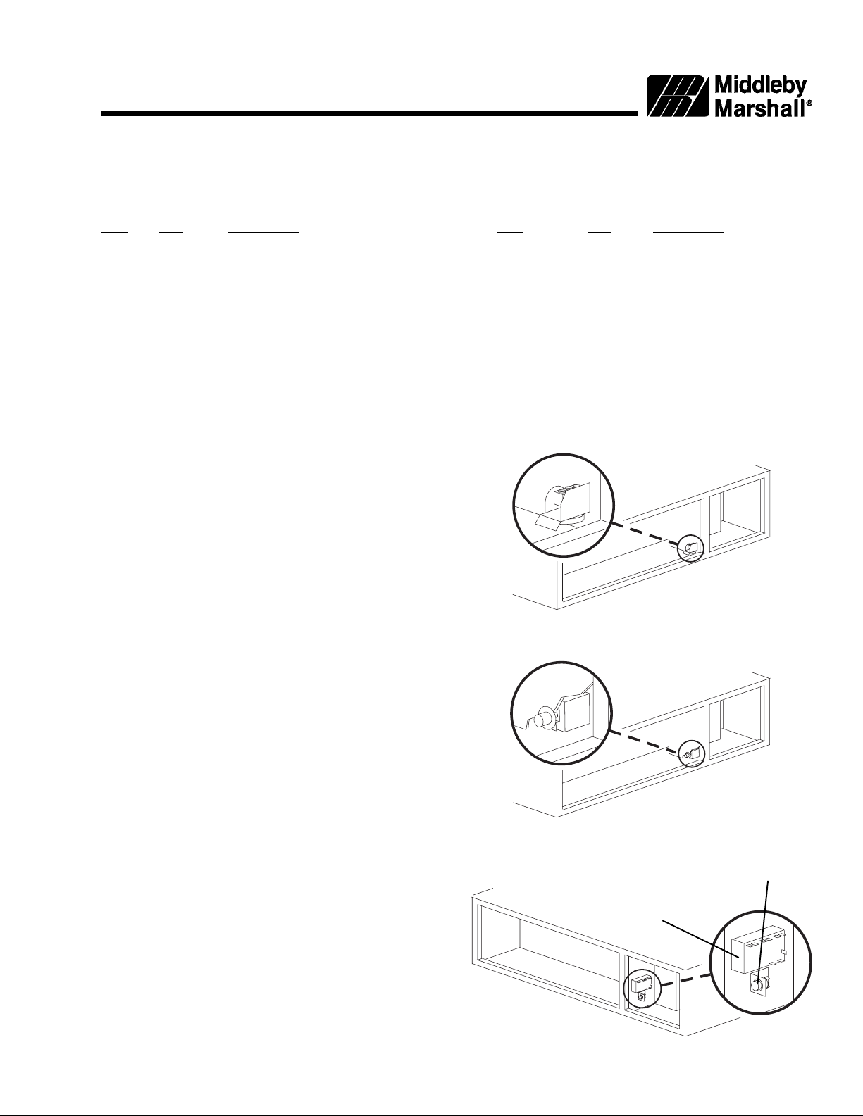
Figure 1
United Electric Type 54
High Limit Control
United Electric Type 55
High Limit/Cooldown
Control
The later (Type 55) United Electric control was
equipped with BOTH high limit and cooldown circuits,
and was used on the following models:
- PS300/310/350/360 Electric (late), 208/240V and
480V UL versions ONLY
For these ovens, the kit replaces the Type 55 control with the Watlow high limit control, and uses the
ovens temperature controller to provide the
cooldown circuit.
Page 1 of 8
Lighted Reset
Switch
Watlow High
Limit Control
P/N 39732
Rev. B V1 5/99
Page 2

B. INSTALLATION
WARNING
BEFORE PERFORMING ANY SERVICE WORK, THE GAS SUPPLY (IF SO EQUIPPED)
THE ELECTRICAL SUPPLY TO THE OVEN
1. Open the machinery compartment and control compartment access panels.
2. Locate the high limit thermo bulb/capillary assembly. Its location is shown in Figure 2. Loosen the set
screw that holds the assembly in place. Remove the thermo bulb/capillary assembly from the mounting tube.
3. Disconnect the wires (2 for the Type 54 control, 4 for the Type 55 control) from the terminals of the
United Electric control. Bundle the loose wires together, and allow them to hang loose for later
reconnection.
4. Remove the mounting screws that hold the United Electric high limit control in place. Then, remove
and discard the high limit control and its mounting screws.
5. Position the new high limit control in place on the left wall of the control compartment, as shown in
Figure 3. When positioning the control:
Ensure that the control is positioned AT LEAST 1 (25mm) back into the compartment to allow the
compartment door to close.
Ensure that additional space is left underneath the control for the reset switch.
MUST BE TURNED OFF.
AND
NOTE: Instead of holding the high limit control in place, you may use the dimensions provided in
Figure 4 to determine the location of the control and its mounting holes.
6. Mark the locations of the two mounting holes for the high limit control. Then, drill the holes using a
3/16 drill bit.
7. Secure the high limit control in place using the kit-supplied 6-32 x 1-5/8 screws and 6-32 nuts.
8. Position the bracket for the reset switch on the left wall of the control compartment, as shown in Figure
3. Note that the face of the bracket with the large, circular switch-mounting hole should face YOU.
Also, the bracket should be positioned AT LEAST 3 (75mm) back into the compartment to allow the
door to close.
9. While holding the bracket in place, mark the locations of the two mounting holes. Then, remove the
bracket and drill the holes using a 3/16 drill bit.
10. Secure the bracket to the panel using the kit-supplied 6-32 x 1/4 screws and 6-32 nuts. DO NOT
INSTALL THE RESET SWITCH INTO THE BRACKET AT THIS TIME.
11. Insert the kit-supplied thermocouple into its mounting sleeve. Position the sleeve so that the mounting
hole is at the base of the thermocouple, not the tip. See Figure 5.
12. Insert the thermocouple and mounting sleeve into the original mounting tube. The set screw opening
in the sleeve should align with the set screw hole on the side of the mounting tube.
Push the thermocouple into the opening until its base seats firmly on the mount. See Figure 6.
13. Insert the thermocouples set screw into the hole on the side of the mounting tube. Tighten the set
screw to hold the thermocouple and sleeve in place.
14. Thread the thermocouples shielded cable into the electrical compartment. Coil the free end of the
cable and fasten it with the kit-supplied nylon wire tie. Be sure to leave enough free cable to reach the
new high limit control.
Page 2 of 8
Page 3
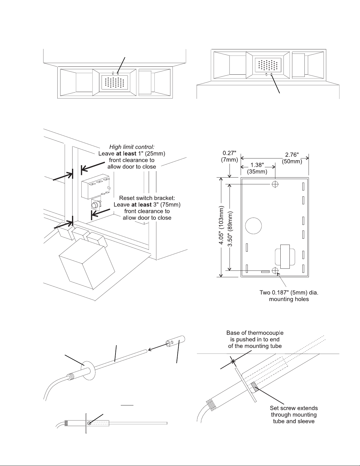
Figure 2
High limit thermocouple location -
lower oven
High limit thermocouple location -
Figure 3 Figure 4
NOT TO SCALE
upper oven
Base
Figure 5
Thermocouple
Hole in sleeve is
next to base of
thermocouple
Figure 6
Sleeve
Page 3 of 8
Page 4

C. WIRING
For the various wiring connections listed below, cut the kit-supplied #18 AWG wires to length. Refer to
Figures 7 and 8 (on pages 6 and 7) for diagrams of the wiring connections.
Lighted Reset Switch Wiring and Installation
14. Using the kit-supplied 1/4 wire connectors, connect the following kit-supplied wires:
- Red wires ................. connect one wire to each RESET terminal on the high limit control
- Black wire ................. connect to terminal NC on the high limit control
- White wire................. connect to terminal L2 on the ovens temperature controller
15. Slip the free ends of these four wires through the circular hole in the reset switch mounting bracket, so
that they hang down in front of the control compartment.
16. Use the kit-supplied 1/4 wire connectors to connect these four wires to the terminals on the lighted
reset switch.
- Terminals 1 and 3 ..... Red wires (these connections are interchangeable)
- Terminal 2 ................ Black wire
- Terminal 4 ................ White wire (kit-supplied)
17. Push the lighted reset switch through the mounting hole in the center of the bracket until it snaps into
place. Be sure to avoid pinching the wires against the sides of the mounting hole.
Cooldown circuit wiring
NOTE: Perform steps 18 and 19 ONLY if you are replacing a UE Type 55 controller. If you are
replacing a UE Type 54 controller (which has no cooldown circuit), skip ahead to Step 20.
18. Attach the ovens
troller, as shown in Figures 7 and 8.
For Ovens with a Digital Temperature Controller:
a. Terminal 9 ................ Black wire (from blower switch)
b. Terminal 10 .............. Brown wire (from blower switch)
For Ovens with an Analog Temperature Controller:
a. Terminal 13 .............. Black wire (from blower switch)
b. Terminal 14 .............. Brown wire (from blower switch)
19. Attach a brown kit-supplied wire between the following terminals on the Temperature Controller:
Digital Controller ............. Terminals 10 and L1
Analog Controller............ Terminals 13 and L1
High Limit Control wiring
20. Using the kit-supplied 1/4 wire connectors, wire the high limit control terminals as follows:
a. Terminal NO ........... Purple wire (originally to UE control)
c. Terminal TC + ........ White wire (to thermocouple) - DO NOT CUT THIS WIRE TO LENGTH.
d. Terminal TC - ......... Red wire (to thermocouple) - DO NOT CUT THIS WIRE TO LENGTH.
f. Terminal L2 ............ White wire (kit-supplied; to neutral on the ovens terminal block)
h. Terminal COM ........ Orange wire (originally to UE control)
existing cooldown wiring to the following terminals on the ovens Temperature Con-
21. Using a 1/4 wire connector, attach a brown kit-supplied wire to the L1 terminal on the high limit
control. Attach the free end of the wire to the L1 terminal on the temperature controller.
Page 4 of 8
Page 5

D. TESTING THE INSTALLATION
22. Remove the thermocouple wires from the TC + and TC - terminals on the high limit control.
23. Attach a Middleby Marshall Thermocouple Source (P/N 27170-0263) to the TC + and TC - terminals on the high limit control, in place of the thermocouple wires. Note that it may be necessary to
attach a pair of terminal connectors to the leads of the Thermocouple Source to allow them to connect
to the high limit controls terminals.
24. Restore the gas supply (if so equipped) and the electrical supply to the oven. Because the control
compartment door is still open, pull the door safety switch out into the service position.
25. Test the operation of the high limit control as follows:
a. Set the Thermocouple Source to a normal operating temperature, between 200°-600°F (93°-315°C).
b. Turn the oven on, and allow it to heat to 600°F (315°C).
c. After the oven has reached the setpoint temperature, set the Thermocouple Source to 700°F (371°C).
The high limit control is set to open at any temperature in excess of 650°F (343°C). This will shut
down the ovens heat circuit and illuminate the Reset Switch lamp.
26. Set the Thermocouple Source to a temperature setting below 600°F (316°C), and depress the Reset
Switch. This should turn off the Reset Switch lamp and restore heat circuit operation.
27. Turn the oven off.
28. If you replaced a UE type 55 controller (with a cooldown circuit), you must set the Thermocouple
Source to a temperature setting below 200°F (93°C). Then, wait for the blowers to turn off.
29. Press the door safety switch in to reset it to normal.
30. Remove the Thermocouple Source from the oven.
31. Reattach the thermocouple wires to the high limit controls terminals as follows:
White wire ................ TC +
Red wire ................... TC -
32. Close the machinery compartment and control compartment access panels, and fasten them in place.
The oven is now ready for normal operation.
Page 5 of 8
Page 6

Page 6 of 8
Figure 7 - United Electric Model 55 replacement: ovens with a cooldown feature
KEY
Page 7

Page 7 of 8
Figure 8 - United Electric Model 54 replacement: ovens without a cooldown feature
KEY
Page 8

A MIDDLEBY COMPANY
Middleby Cooking Systems Group 1400 Toastmaster Drive Elgin, IL 60120 USA (847) 741-3300 FAX (847) 741-4406
Middleby Corporation Service Hotline 1-800-238-8444
www.middleby.com
Page 8 of 8
 Loading...