

Page 1
PS540G SERIES GAS FIRED:
A MIDDLEBY COMPANY
Parts Manual
with Wiring Diagrams
for domestic and standard export ovens
SPL100505-PF-BD
October 5, 2005
Serial # Code
First 4 digits - order of production
Fifth digit - model specific
Sixth and Seventh digit - month of production
Eighth and Ninth digit - year of production
Starting Serial # 000160104 & after
Serial Tag Location
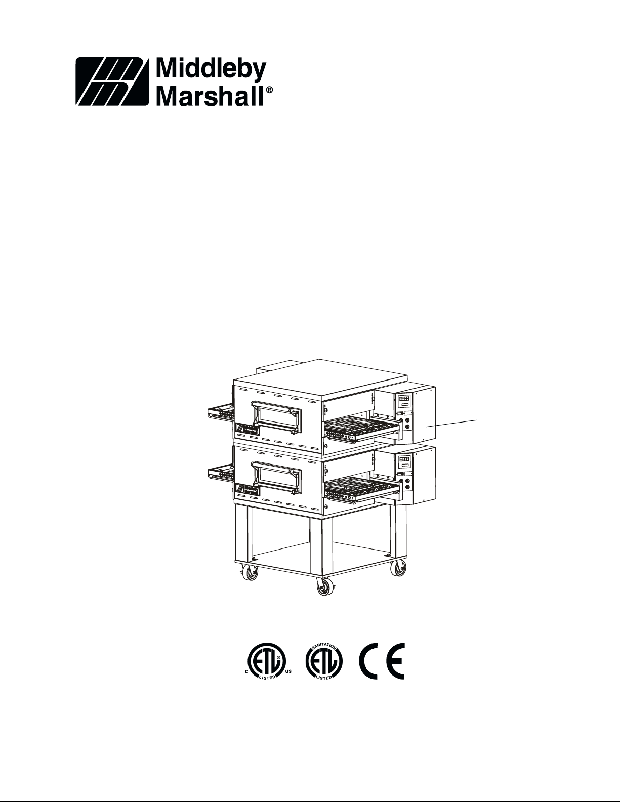
PS540G-DoubleShown with “New
Style” Front Window
Assembly.
1-847-741-3300 fax 1-847-741-4406 (Parts Department)
©2005 Middleby Marshall Inc.
Table of Contents: Page 2
www.middleby.com
email: techsupport@middleby.com
Page 2

Table of Contents
Spec Sheet .............................................................................................................................................. 3
Oven and Electrical Specifications .......................................................................................................... 6
Key Parts ................................................................................................................................................. 7
View of Oven Panels, Window and Legs (Earlier Production) .................................................................8
Parts for Oven Panels, Window and Legs (Earlier Production ................................................................ 9
View of Oven Panels, Window and Legs (Later Production) ................................................................. 10
Parts for Oven Panels, Window and Legs (Later Production ................................................................ 11
View of Right-hand Control Compartment .............................................................................................. 12
Parts for Right-hand Control Compartment ............................................................................................ 13
View of Blower Area ............................................................................................................................... 14
Parts for Blower Area ............................................................................................................................. 15
View of Blower/Motor Compartment ....................................................................................................... 16
Parts for Blower/Motor Compartment ..................................................................................................... 17
View of Gas Burner & Piping ................................................................................................................. 18
Parts for Gas Burner & Piping ............................................................................................................... 19
View of “Single” Belt Conveyor .............................................................................................................. 20
Parts for “Single” Belt Conveyor ............................................................................................................ 21
View of “Split” Belt Conveyor ................................................................................................................. 22
Parts for “Split” Belt Conveyor ............................................................................................................... 23
PS540G OVEN INSTALLATION KIT ....................................................................................................24
PS540G Single Oven Option Base Kit ................................................................................................... 25
PS540G Double Oven Option Base Kit ................................................................................................. 26
PS540G Triple Oven Option Base Kit (Outriggers) ............................................................................... 27
Standard Finger Configuration ............................................................................................................... 28
Wiring Diagram, 208-240 volt 50/60 Hz, 1 Phase 3W 50141 Rev. F2 US/UK/CANADA ...................... 29
Ladder Wiring Diagram, 208-240 volt 50/60 Hz, 1 Phase 3W 50141 Rev. F1 US/UK/CANADA .......... 30
Wiring Diagram, 208-240 volt 50/60 Hz, 1 Phase 3W 52059 Rev. D DN .............................................. 31
Wiring Diagram, 208-240 volt 50/60 Hz, 1 Phase 3W 52065 Rev. D DUT ............................................ 32
Wiring Diagram, 208-240 volt 50/60 Hz, 1 Phase 3W 52053 Rev. D FR ............................................... 33
Wiring Diagram, 208-240 volt 50/60 Hz, 1 Phase 3W 52055 Rev. D GM .............................................. 34
Wiring Diagram, 208-240 volt 50/60 Hz, 1 Phase 3W 52067 Rev. D GK .............................................. 35
Wiring Diagram, 208-240 volt 50/60 Hz, 1 Phase 3W 52061 Rev. D IT................................................. 36
Wiring Diagram, 208-240 volt 50/60 Hz, 1 Phase 3W 52057 Rev. D SP ............................................... 37
Wiring Diagram, 208-240 volt 50/60 Hz, 1 Phase 3W 52063 Rev. D SW .............................................. 38
2
Page 3

3
Page 4
1
3
GAS INLET
3
3
2
ELECTRICAL JUNCTION BOX
3
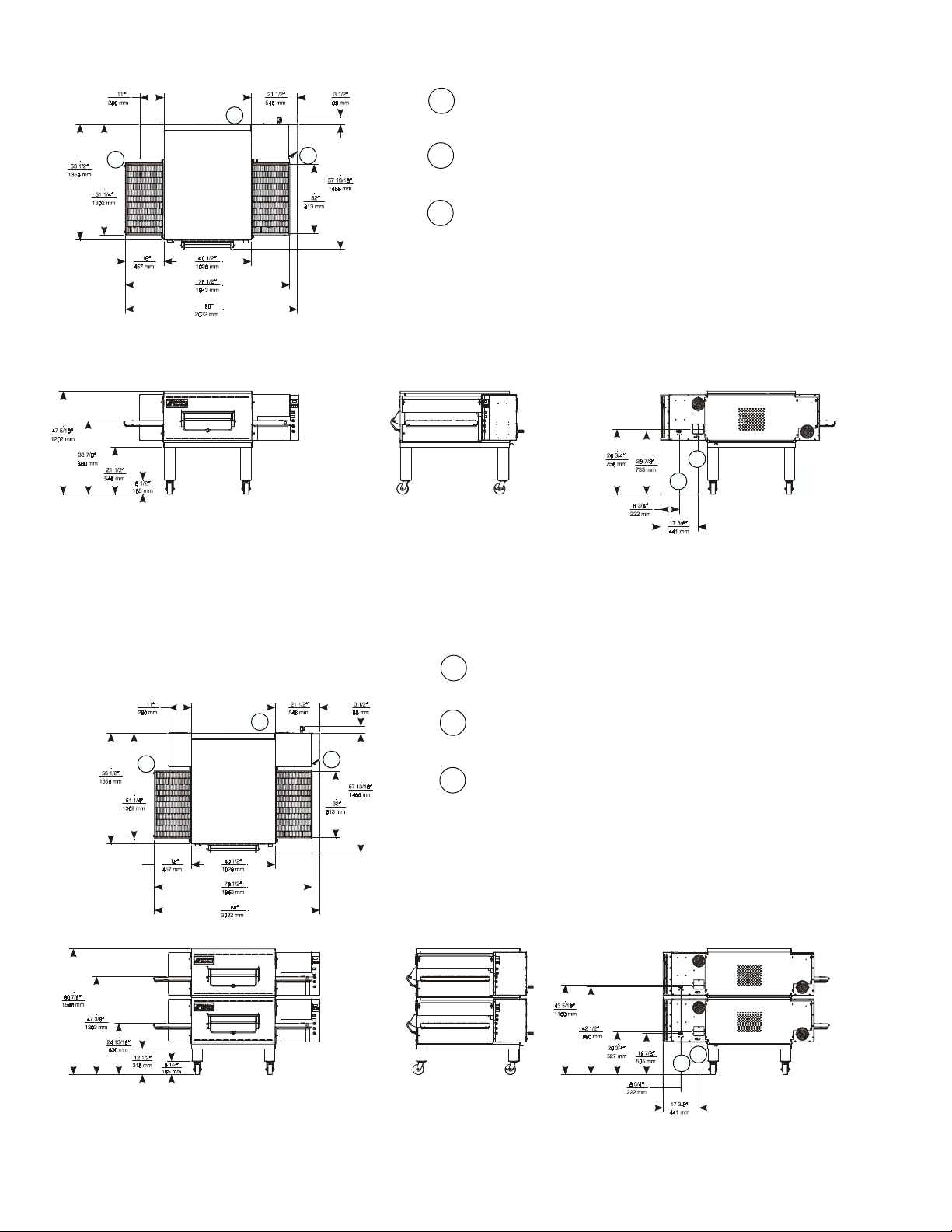
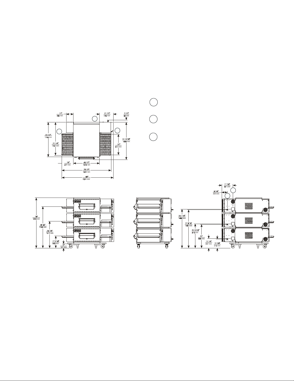
RECOMMENDED MINIMUM CLEARANCES:
Rear of Oven to Wall - 6″ (150mm)
Non-control End of Oven to Wall - 0″
Control End of Oven to Wall - 0″
2
1
MODEL PS540 SINGLE OVEN DIMENSIONS
GAS INLET
1
3
3
3
2
ELECTRICAL JUNCTION BOX
RECOMMENDED MINIMUM CLEARANCES:
3
Rear of Oven to Wall - 6″ (150mm)
Non-control End of Oven to Wall - 0″
Control End of Oven to Wall - 0″
2
1
MODEL PS540 DOUBLE OVEN DIMENSIONS
4
Page 5
GAS INLET
1
3
3
3
2
ELECTRICAL JUNCTION BOX
RECOMMENDED MINIMUM CLEARANCES:
3
Rear of Oven to Wall - 6″ (150mm)
Non-control End of Oven to Wall - 0″
Control End of Oven to Wall - 0″
2
1
MODEL PS540 TRIPLE OVEN DIMENSIONS
5
Page 6

PS540 SERIES OVEN SPECIFICATIONS
Conveyor Belt Width 32″ (813mm)
Heating Zone Length 40-1/2″ (1028mm)
Baking Area Square Feet 9 sq. ft. (0.84 sq. m.)
Overall Dimension
Standard Single Oven w/Legs 80″ (2032mm) L ×
Overall Dimension
Double Oven 80″ (2032mm) L ×
Overall Dimension
Triple Oven 80″ (2032mm) L x
Weight of Single Oven 925 lb (419kg)
Shipping Weight 1,100 lb (498.3kg)
Shipping Cube Approx. 132 ft3 (3.74 m3)
Operating Range 110,000 BTU/hr
Maximum Operating Temperature 550°F (287°C)
Warm-up Time 10 min.
Gas Oven Inlet Line Size 3/4″ (19mm) ID for each oven
Minimum Gas Meter Rating 450 cu.ft./hr. (12.74m3h) for 1 to 2 ovens
Add 180 cu.ft./hr (5.1m3h) for each additional oven
Minimum Gas Pipe Size
Natural (must be dedicated line) 2″ (51mm) ID for 1, 2, or 3 ovens
Propane (must be dedicated line) 2″ (51mm) ID for 1, 2, or 3 ovens
Gas Pressure
Natural 6″ to 12″ Water Column (13.8 to 29.9 mbar)
Propane 11.5″ to 12″ Water Column (28.7 to 29.9 mbar)
Gas Valve 0.75″ (19mm) ID full-flow, gas, shutoff valve installed in oven inlet gas line.
A separate connection and valve must be provided for each oven.
Recirculating Air Fan One fan at 2300 RPM
Air Velocity 3000 fpm (1524 cm/sec) (Average)
Bake Time 3 min. 0 sec. Bake Time minimum
61-5/16″ (1557mm) W ×
47-5/16″ (1202mm) H ×
61-5/16″ (1557mm) W ×
60-15/16″ (1548mm) H x
61-5/16″ (1557mm) W ×
77-1/2″ (1969mm) H ×
(116.0 mJ/h)
(27,720 kcal)
(32.2 kW/hr)
30 min. 0 sec. Bake Time maximum
SERIES PS540 ELECTRICAL SPECIFICATIONS
Main Blower & Control Circuit Phase Frequency Amperage Poles Wires
Elements Voltage Voltage Draw
208-240V 208-240V 1 Ph 50/60 Hz 4.1 Amp 3 Pole 3 Wire
6
(2 hot, 1 grd)
Page 7
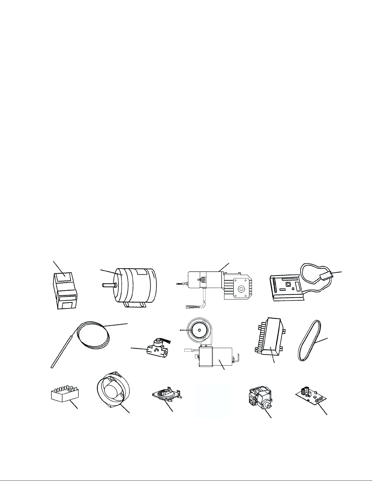
KEY PARTS
PS540-SERIES GAS OVEN KEY PARTS
ITEM PART NO. ENGLISH DESCRIPTION QUANTITY
1 58504 Temperature Controller 1
2 44687 Blower/Fan Motor 1
3 47797 Conveyor Drive Motor, Standard Speed 1 or 2
3A 47799 Conveyor Drive Motor, High Speed 1 or 2
3B 45017 Kit, Brushes, Springs & Caps 1
3C 50265 Pickup, Sensor 1
4 58323 Conveyor Speed Control 1
5 33812-3 Thermocouple 3
6 41647 Modulating Gas Valve 1
7 50275 Burner & Motor Assembly 1
8 50239 Ignition Control Module (kit) 1
9 See RPM Kit Blower Belt, page 17 1
10 33983 High Limit Control Module 1
11 36451 Cooling Fan 2
12 50610 Air Switch 2
13 50274 Control Valve, Gas, 1/2" 1
14 31651 Signal Amplifier
1
1
2
5
6
10
11
12
3
4
9
8
7
13
14
7
Page 8
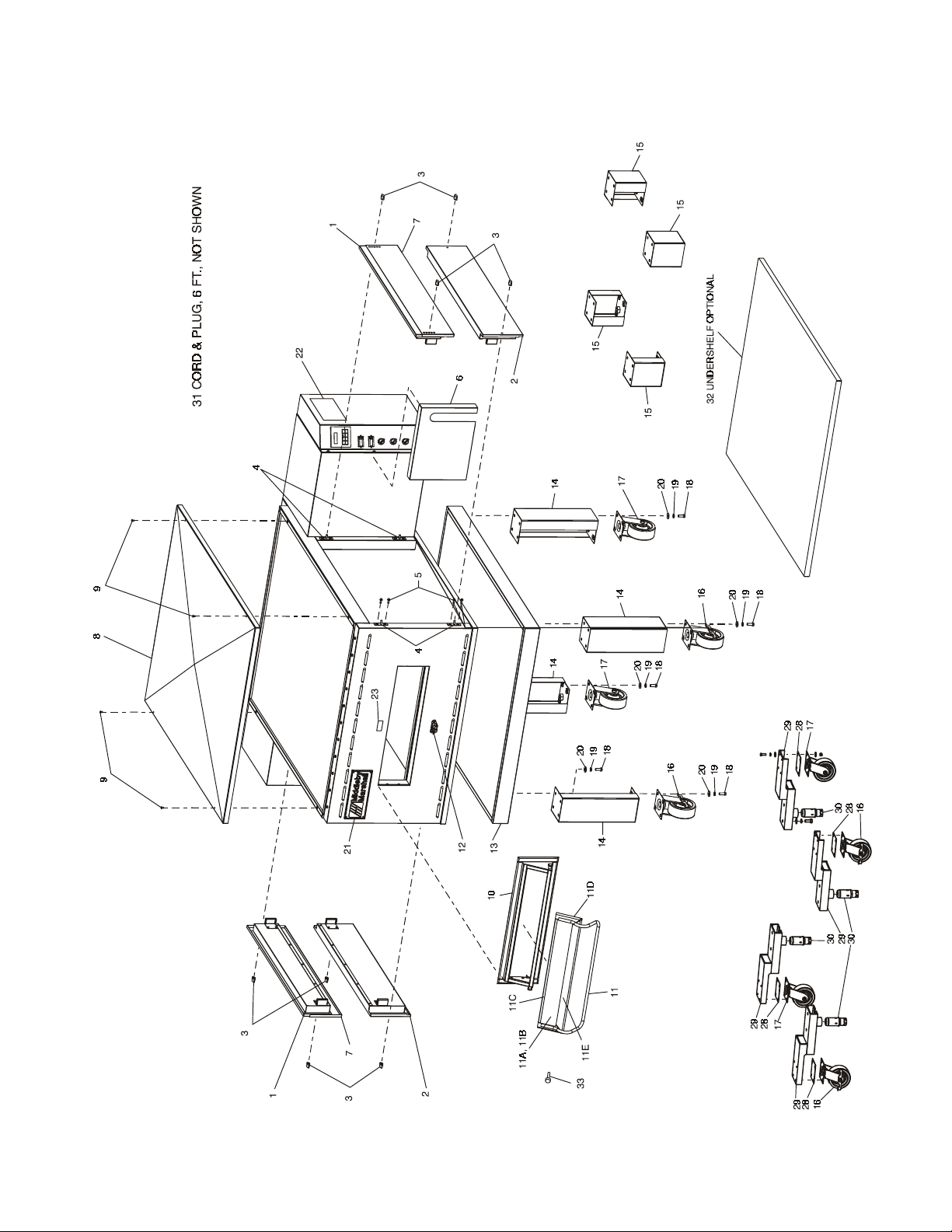
View of OVEN PANELS, WINDOW (EARLIER PRODUCTION) AND LEGS
8
Page 9

Parts for OVEN PANELS, WINDOW (EARLIER PRODUCTION) AND LEGS
1 2 49947 UPPER END PLUG ASSEMBLY, INCLUDES ITEM 7
2 2 49946 LOWER END PLUG ASSEMBLY
3 8 36452 WING NUT, PLASTIC 1/4-20
4 8 45449 END PLUG MOUNTING PLATE ASSEMBLY
5 16 21296-0005 SCREW, HEX WSHHD12-14 × 3/4″, SS BSD
6 1 51094 CONVEYOR CHAIN COVER
7 2 50637 EYEBROW, ADJUSTABLE
8 1 35900-0011 COVER, TOP
9 4 21256-0008 SCREW, 10-32 × 3/8″ 18-8 SL TRUS S
10 1 37900-0103 WINDOW MOUNTING FRAME WELDMENT (EARLIER MODELS)
ITEM QTY. P/N DESCRIPTION
11 1 30285 GLASS DOOR ASSEMBLY (EARLIER MODELS)
11A 1 22140-0017 GLASS, 23-1/8″ × 4-1/4″
11B 1 17130-0006 SEALANT
11C 1 3 028 6 TOP FRAME
11D 1 30287 FRAME WITH HANDLE
11E 1 33300-0273 TUBE, HINGE
9
12 1 42400-0087 WINDOW LATCH ASSEMBLY (EARLIER MODELS)
13 1 54606 COMPLETE BASE WELDMENT
14 4 37900-0024 LEG/TOP PLATE WELDMENT, 15″ TALL
15 4 37900-0102 LEG 6″ H/TOP PLATE WELDMENT, 6″ TALL
16 2 22290-0009 CASTER, SWVL W/BRAKE FLAT PLATE
17 2 22290-0010 CASTER SWVL FLAT PLATE
18 A/R 220373 SCREW, HEX HEAD, 3/8″ - 16 × 1″ SST
19 A/R 21422-0001 WASHER, LOCK SPLIT 3/8″
20 A/R 21416-0001 FLAT WASHER, 3/8″ ZP
21 1 45739 NAME PLATE, MIDDLEBY
28 4 45205 QUAD CASTER SPACER
29 4 45209 QUAD OUTRIGGER WELDMENT
30 4 45206 QUAD ADJUSTMENT FOOT INSERT
31A 1 49975 CORD & PLUG, 6-20P, 6' LONG, U.S.
32 1 58705 UNDERSHELF (OPTIONAL)
31B 1 49976 CORD & PLUG, OVERSEAS, CE
33 2 34121-0003 SCREW, THUMB PIVOT
Page 10
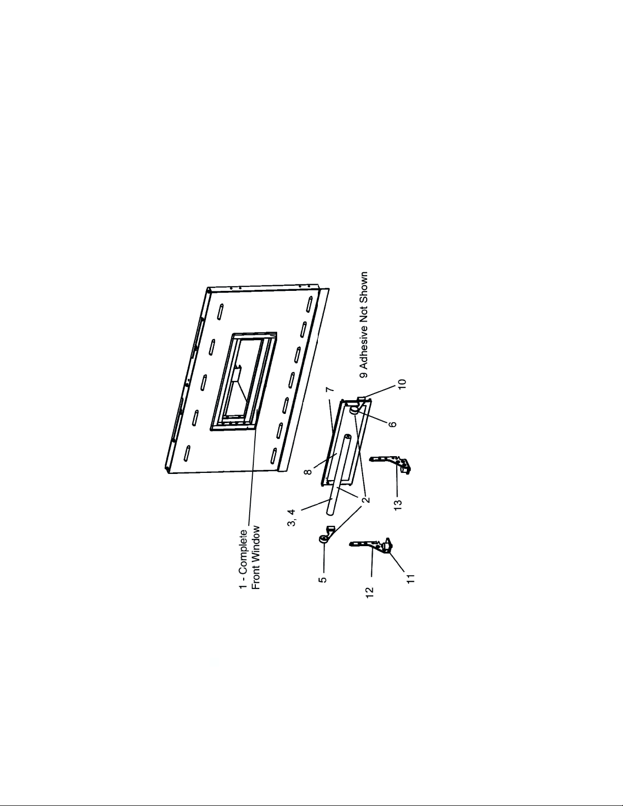
View of WINDOW–Later Production (Front Window Change Used After March, 2004)
10
Page 11

1 1 51054 ASSEMBLY ,WINDOW, w/HANDLE, ITEMS 1-10
2 1 51081 ASSEMBLY, HANDLE, ITEMS 3-6
3 1 M10092 HANDLE, OUTER
4 1 M10127 HANDLE, INNER THREADED
5 1 M1115 HANDLE, BRACKET (LEFT)
6 1 M1116 HANDLE, BRACKET (RIGHT)
7 1 51087 FRAME AND WINDOW, ITEMS 8-9
8 1 M10198 GLASS, 4.1″ X 15.150″
9 1 M1965 ADHESIVE (NOT SHOWN)
10 2 M1118 SCREW–ATTACHES HANDLE
11 2 30927 BUMPER
12 1 51210 BRACKET, WINDOW HINGE (LEFT)
ITEM QTY. P/N DESCRIPTION
13 1 51211 BRACKET, WINDOW HINGE (RIGHT)
Parts for WINDOW–Later Production (Front Window Change Used After March, 2004)
11
Page 12
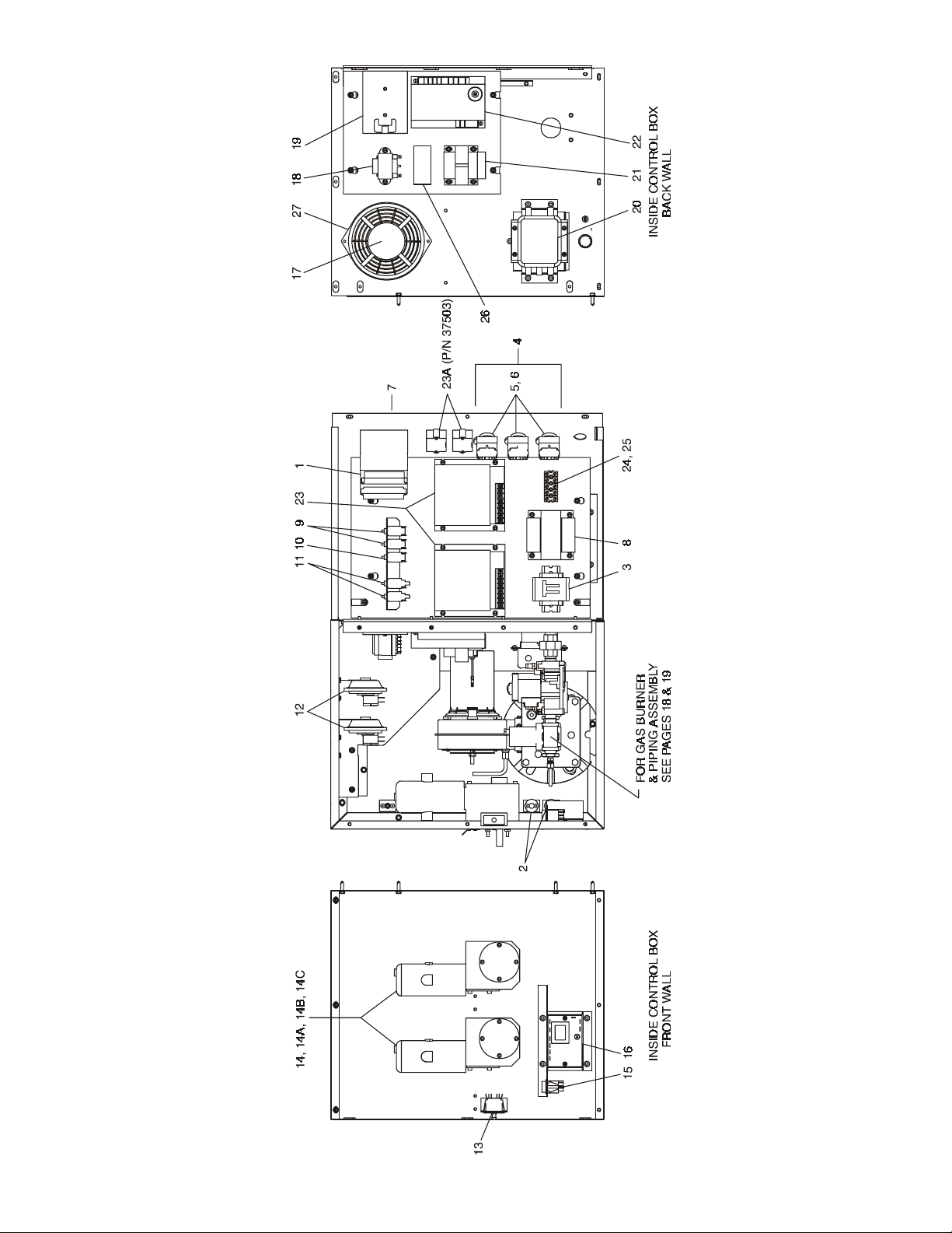
View of RIGHT-HAND CONTROL COMPARTMENT
12
Page 13

Parts for RIGHT-HAND CONTROL COMPARTMENT
1 1 58504 TEMPERATURE CONTROL
2 2 33812-3 THERMOCOUPLE, TYPE J SHIELDED 9.50 × 60″
3 1 28041-0011 CONTACTOR, 208/240V
4 3 46521 KIT, BLOWER SWITCH CONTAINS ((1) 44697, (1) 44696)
5 3 44697 CONTACT BLOCK
6 3 44696 SELECTOR SWITCH
8 1 31504 TRANSFORMER, 230V (P)/120V (S) 200VA
9 2 45036 CIRCUIT BREAKER, 240V 3A
10 1 45644 CIRCUIT BREAKER, 240V 1A
11 2 46831 CIRCUIT BREAKER, 240V 8A
12 2 50610 AIR SWITCH, 0.16″ WC
13 1 28021-0047 INTERLOCK SWITCH, 10A NO2P
ITEM QTY. P/N DESCRIPTION
14 A/R 47797 MOTOR, GEAR 1/50HP 1350:1, STANDARD
14A A/R 47799 MOTOR, HIGH SPEED OPTION 311:1
14B A/R 50265 SENSOR, PICKUP
13
15 1 35145 SWITCH, PB MOLVENO 250V, RESET, 1/30 HP, 311:1
14C A/R 45017 KIT, BRUSHES, SPRINGS AND CAPS
16 1 33983 ELECTRIC HI-LIMIT CONTROL, 240V
17 1 36451 COOLING FAN, 230V AC
18 1 41872 TRANSFORMER, 240V (P)/24V (S) 25VA
19 1 31651 SIGNAL AMPLIFIER, 4-20VDC
20 1 33813 RFI FILTER, TYPE F1780DD20
21 1 32108 TRANSFORMER, 240V (P)/24V (S) 65VA
22 1 50239 SPARK IGNITION MODULE, 24VAC 50/60Hz
23 1(2) 58323 CONVEYOR SPEED CONTROL W/DIGITAL SPEED DISPLAY
24 1 44390 TERMINAL BLOCK, MAIN POWER, 3-POLE, 50A, 600V
23A 1(2) 37503 DIGITAL SPEED CONTROL (DISPLAY ONLY)
25 1 39258 TERMINAL BLOCK, MAIN POWER, 5-POLE, 50A, 600V
26 1 50794 RELAY, 24V, GAS TRAIN
27 1 31497 FINGER GUARD
Page 14

View of BLOWER AREA
3A (NOT SHOWN)
NEVER SEIZE LUBRICANT
14
Page 15

APPLIED TO THREADS BEFORE REINSTALLING
Parts for BLOWER AREA
1 1 51157 PULLEY, 1GRV 3.0PD AK32H, 3.25″ DIA.
2 1 48855 WELDMENT, BRG BRACKET PS540G
ITEM QTY. P/N DESCRIPTION
3 22 220373 SCREW, HH 3/8″ - 16 × 1″ SS T
4 A/R A11039 SPLIT LOCK WASHER 3/8″ ZP
3A A/R 17110-0017 NEVER SEIZE LUBRICANT - USED ON ITEMS 3 & 7
5 A/R 21416-0001 FLAT WASHER 3/8″ SS
6 2 22072-0025 BEARING, PILLOW BLOCK 5/8″
7 8 21326-0002 SCREW, HX HD GRS 3/8″ - 16 × 5-1/2″
8 6 2000203 SCREW ,HX W/HD 10 - 32 × 3/8″ ZC
9 1 48872 BACK WALL SHROUD
10 1 48803 AIR INLET RING
11 8 35900-0108 FAN ORIFICE STAND OFF TUBE
12 1 50643 FAN DRIVE SHAFT
13 1 21651-0010 KEY, SQ 3/16″ × 3/16″ × 1.00″ STL
14 1 48862 AXIAL FAN, 14″ DIAMETER
15 1 51110 INR/OTR BACK WELDMENT
16 1 50222 SPECIAL BUSHING, 5/8″ ID - 3/16″ × 3/32″ KEY
17 2 35323 COUPLING, COLLAR SPLIT 5/8″ DIAMETER
18 4 50271 ROLL PIN, PLN 5/32″ × 7/16″
15
Page 16

View of BLOWER/MOTOR COMPARTMENT
16
Page 17

Parts for BLOWER/MOTOR COMPARTMENT
1 1 28021-0047 INTERLOCK SWITCH 10A NO2P
2 1 28021-0061 MOMENTARY SWITCH - 10A NO 2 POLE
3 1 44687 MOTOR 1/2 HP
ITEM QTY. P/N DESCRIPTION
4 1 49953 MOTOR MOUNTING BRACKET WELDMENT
5 1 50449 MOTOR SUPPORT BRACKET
6 8 1513D8805 SCREW, HEX HD 3/8″-16 × 3/4″ - N P
7 8 21422-0001 LOCK WASHER, SPLIT 3/8″ ZP
H 5/8 SPLIT BUSHING 50222
H 5/8 SPLIT BUSHING 50222
8 8 21416-0001 FLAT WASHER SS 3/8″
9 4 A3896 MACHINE SCREW, HEX HD 5/16″-18 × 1″ 18-8
10 4 3023A8807 FLAT WASHER 5/16″ SAE NP
11 4 21126-0004 HEX NUT SS 5/16-18
12 4 21421-0004 LOCK WASHER 5/16″
13 1 36451 COOLING FAN 230V AC
14 1 31497 FINGER COOLING FAN GUARD
15 1 33812-3 THERMOCOUPLE, TYPE “J” SHIELDED 9.50 × 60″ (TEMP CONTROL)
16 1 21651-0010 KEY - MOTOR, 3/16″ X 3/16″ X 1 ″
17 1 SEE CHART MOTOR, PULLEY
18 1 SEE CHART BUSHING, SPLIT
19 1 SEE CHART BELT, GRIP NOTCH
P/N W/SPLIT BUSHING SPLIT BUSH P/N DESCRIPTION P/N FAN
50545 50 AK51H PULLEY, 4.95″ 51161 AX63 34259 2300
51079 50 AK46H PULLEY, 4.45″ 51160 AX62 50584 2040
50544 60 AK44H PULLEY, 4.25″ 51159 AX61 50450 2300
RPM KIT HERTZ MOTOR PULLEY MTR PULLEY P/N BELT SIZE BELT RPM OF
STANDARD H 5/8 SPLIT BUSHING 50222
51077 60 AK39H PULLEY, 3.75″ 51158 AX61 50450 2050
OPTIONAL H 5/8 SPLIT BUSHING 50222
SLOW BRAKE
H 5/8 SPLIT BUSHING 50222
51403 50 AK56H PULLEY, 5.45″ 51404 AX62 50584 2485
17
Page 18

5 KIT, NATURAL TO LP - NOT SHOWN
View of GAS BURNER AND PIPING ASSEMBLY
NOT SHOWN
23 IGNITOR SENSOR -
18
Page 19

(INCLUDES ITEMS 1A, 6 AND 9)
Parts for GAS BURNER AND PIPING ASSEMBLY
1 1 50274 1/2″ GAS CONTROL VALVE (Conversion Required for Propane)
1A 1 28092-0018 VALVE KIT CONVERT FROM NATURAL GAS TO PROPANE
ITEM QTY. P/N DESCRIPTION
1B 1 28092-0019 VALVE KIT CONVERT FROM PROPANE TO NATURAL GAS
2 5 23153-0004 1/2″ CLOSE NIPPLE - BLK
3 1 23151-0032 1/2″ × 3″ NIPPLE - BLK
4 1 23051-0003 1/2″ PIPE UNION
5 1 50543 NATURAL TO PROPANE CONVERION KIT, PS540 (NOT SHOWN)
6 1 22174-0006 ORIFICE #53 DRILL BY-PASS - PROPANE (.059)
7 1 50273 ORIFICE #40 DRILL BY-PASS - NATURAL (.098)
8 1 50640 ORIFICE #43 DRILL, MAIN BURNER - NATURAL (.1935″) PS540
9 1 50641 ORIFICE #30 DRILL, MAIN BURNER - PROPANE (.120″) PS540
10 1 23015-0004 1/2″ COUPLING NPT
11 1 50268 1/4″ TUBE, BY-PASS
19
12 1 50275 GAS BURNER ASSEMBLY
13 1 41647 VALVE, MODULATING, 1/2″
14 1 22550-0006 FLANGE, BURNER
15 1 23115-0009 VALVE, GAS SHUTOFF 1/2″ × 1/ 2″
16 1 30002 PLUG, 1/8 NPT
17 1 36937 GASKET
18 1 37000-0781 ASSY, PIPE CLAMP
19 2 44888 FITTING, COMPRESSION
20 1 45667 TEE, PIPE 1/2″ × 1/2″ × 1/2″
21 3 48742 BUSHING, REDUCER
22 1 50266 CROSS, PIPE 1/2″ × 1/2″
23 1 55091 IGNITOR (SENSOR)
24 1 58827 IGNITION CABLE
25 1 58828 TARGET AND VENTURE
26 2 Contact Factory PRESSURE TAP
27 1 38811 BURNER/BLOWER MOTOR
Page 20

View of “Single” Belt Conveyor
20
39 (NOT SHOWN)
HEYCO PLIERS
Page 21

W/SCREW
INCLUDES ITEMS 27 & 28
WELDMENT - DRIVE
INCLUDES ITEMS 19, 21, 29, 30, 31 & 32
INCLUDES ITEMS 24 & 33
STANDARD
STANDARD MOTOR
HIGH SPEED
RELIEF ON PICK-UP, GEAR MOTOR
24 12 22229-0003 CONVEYOR DRIVE SPROCKET 2.0″ OD
25 1 35000-1011 IDLER SHAFT - CONVEYOR
ITEM QTY. P/N DESCRIPTION
26 1 54961 CONVEYOR FRAME ASSEMBLY - DRIVE
27 1 54960 COMPLETE CONVEYOR FRAME
29 1 22011-0013 SHAFT COLLAR W/SCREW
28 1 54948 DRIVE SIDE ASSEMBLY - CONVEYOR
30 1 35000-1013 DRIVE SHAFT ADAPTER
Parts for “Single” Belt Conveyor
1/2P 32″ × 204″ 2.84/11 S
CONTAINS ((1) 33900-0016,
(4) 33900-0017, (1) 33900-0018)
KIT(NOT SHOWN)
LINK
32 1 49400-0012 DRIVE SHAFT ASSEMBLY
31 2 35000-1080 NYLON SPACER 3/4″ ID 1-1/4″ OD
33 1 35000-1012 DRIVE SHAFT - CONVEYOR
34 1 55027 STOP, SIDE END CONVEYOR EXT
35 1 55028 STOP, BACK SIDE CONVEYOR EXT
INCLUDES ITEMS 17 & 18
36 2 35900-0255 CRUMB PAN W/SLOTS - CONVEYOR -
37 2 35900-0305 CRUMB PAN - CONVEYOR - SOLID
38 1 OR 2 47797 MOTOR, GEAR 1/50HP 1350:1,
38A 1 OR 2 47799 MOTOR, GEAR 1/30HP 311:1,
WELDMENT - IDLER
INCLUDES ITEMS 19, 20, 21, 22 & 23
39 1 50795 HEYCO PLIERS, REMOVES STRAIN
38B 1 OR 2 45017 KIT, BRUSHES, SPRINGS, AND CAPS
INCLUDES ITEMS 24 & 25
2 1 22450-0225 CONVEYOR BELT,
ITEM QTY. P/N DESCRIPTION
3 A/R 33900-0032 CONVEYOR CHAIN, SS WIRE1 FT
4 1 51380 KIT, MASTER LINK,
8 4 2001371 NUT, KEPS 10-32, ZP
9 1 50265 CONVEYOR CONTROL PICKUP
10 1 49400-0050 ROLLER CHAIN ASSEMBLY, W/MASTER
10A 1 22273-0002 MASTER LINK
11 1 22151-0002 SPROCKET, #35-10T-5/8″− SHAFT
12 1 22151-0003 SPROCKET, #35-15T-1/2″−MOTOR
14 2 35900-0398 PIVOT PLATE - CONVEYOR FRAME
15 4 21176-0002 LOCKNUT, HEX SS 3/8″-16
21
16 1 54975 CONVEYOR FRAME ASSEMBLY - IDLER
17 1 54974 COMPLETE CONVEYOR FRAME
19 4 22034-0003 BUSHING, FLANGE 3/4″ OD, × 5/8″ ID N/D
18 1 54970 IDLER SIDE ASSEMBLY - CONVEYOR
20 2 35000-1008 SCREW, ADJ - CONVEYOR IDLER
21 4 54947 CONVEYOR SHAFT SUPPORT BRACKET
22 2 37000-0413 IDLER SHAFT SUPPORT BRACKET
23 1 49400-0014 IDLER SHAFT ASSEMBLY
Page 22

View of “Split” Belt Conveyor
22
42 (NOT SHOWN)
HEYCO PLIERS
Page 23

INCLUDES ITEMS 25, 26 & 27
23 2 37000-0413 IDLER WELDMENT
ITEM QTY. P/N DESCRIPTION
24 1 35525 IDLER SHAFT ASSEMBLY, SPB
25 2 21415-0001 FLAT WASHER, BRONZE
26 1 35000-1535 REAR CONVEYOR IDLER SHAFT, 16-3/8″
ASSEMBLY, 33″
27 1 42400-0354 FRONT CONVEYOR IDLER SHAFT
INCLUDES ITEMS 12, 17, 20, 22, 29, 30,
28 1 54986 CONVEYOR FRAME-DRIVE ASSY, SPB
Parts for “Split” Belt Conveyor
31, 32, 35 & 36
29 1 22011-0014 SPLIT-SHAFT COLLAR
30 2 35000-1080 NYLON SPACER 3/4″ ID 1-1/4″ OD
INCLUDES ITEMS 33 & 34
31 1 35000-1531 NYLON SPACER
32 1 35524 DRIVE SHAFT ASSEMBLY, SPB
DRIVE WELDMENT
33 1 35900-0022 REAR CONVEYOR DRIVE SHAFT, 17.62″
34 1 49400-0018 FRONT CONVEYOR DRIVE SHAFT, 35″
35 1 35900-0023 BUSHING, SPROCKET-FRONT DRIVE
36 1 54960 COMPLETE CONVEYOR FRAME-
37 1 55027 STOP, SIDE END CONVEYOR EXT
38 1 55028 STOP, BACK SIDE CONVEYOR EXT
39 2 35900-0255 CRUMB PAN W/SLOTS - CONVEYOR
40 2 35900-0305 CRUMB PAN - CONVEYOR
41 2 47797 MOTOR, GEAR 1/50HP 1350:1 (STD SPEED
41A 2 47799 MOTOR, GEAR 1/30HP 311:1 (HIGH SPEED)
41B 2 45017 KIT, BRUSHES, SPRINGS, AND CAPS
RELIEF ON PICK-UP, GEAR MOTOR
42 1 50795 HEYCO PLIERS, REMOVES STRAIN
15″ × 146″ 2.86/5 SP
2 2 22450-0226 CONVEYOR BELT, 1/2P
ITEM QTY. P/N DESCRIPTION
3 A/R 33900-0037 CONVEYOR CHAIN, SS WIRE1 FT
CONTAINS ((1) 33900-0016,
(1) 33900-0017, (1) 33900-0018)
4 2 51382 KIT, MASTER LINK,
8 8 2001371 NUT, KEPS 10-32, ZP
KIT(NOT SHOWN)
9 2 50265 CONVEYOR CONTROL PICKUP
2.0″ OD W/SCREW
INCLUDES ITEMS 17, 19, 20, 21, 22, 23 & 24
WELDMENT - IDLER
17 16 22229-0003 CONVEYOR DRIVE SPROCKET
10 1 49400-0070 ROLLER CHAIN ASSEMBLY, SPB 15″
10A 1 22273-0003 MASTER LINK
11 1 49400-0051 ROLLER CHAIN ASSEMBLY, SPB 26-1/2″
11A 1 22273-0003 MASTER LINK
12 2 22159-0003 SPROCKET, #25-20T-5/8″ − SHAFT
13 2 22159-0004 SPROCKET, #25-30T-1/2″ − MOTOR
15 2 35900-0398 PIVOT PLATE - CONVEYOR FRAME
16 4 21176-0002 LOCKNUT, HEX SS 3/8″-16
18 1 54987 CONVEYOR FRAME ASSEMBLY - IDLER
19 1 54974 COMPLETE CONVEYOR FRAME
20 4 22034-0003 BUSHING, FLANGE 3/4″ OD, × 5/8″ ID N/D
21 2 35000-1008 SCREW, ADJ - CONVEYOR IDLER
22 4 54947 CONVEYOR SHAFT SUPPORT BRACKET
23
Page 24

PS540 OVEN INSTALLATION
REQUIRED KITS AND EQUIPMENT
TYPE PS540 PS540 Single PS540 Double PS540 Triple
OF Gas Oven Oven Option Oven Option Oven Option
INSTALLATION Installation Base w/15″
Kit P/N Casters & Top Casters & Top & Top
51100 Kit P/N Kit P/N Kit P/N
PS540 Single Gas Oven 1 1
PS540 Double Gas Oven 2 1
PS540 Triple Gas Oven 3 1
Legs, Base w/6″
34832 34833 51139
Legs, Base w/Casters
PARTS LIST FOR SERIES PS540 GAS OVEN
INSTALLATION KIT
P/N 51100
(Two required for double oven)
(Three required for triple oven)
ITEM
NO. QTY PART NO. DESCRIPTION
1 1 22361-0001 FLEXIBLE GAS HOSE, 3/4″ X 48″
2 1 55027 CONVEYOR END STOP
3 1 55028 CONVEYOR LEFT REAR STOP
4 1 50664 SERIES PS540 OWNER/OPERATOR MANUAL
1
6
2
3
4
5
PS540-Series Gas Oven Installation Parts
24
Page 25

Model PS540 Single Oven
Option Base with Legs and Top
PARTS LIST FOR PS540 SERIES SINGLE OVEN OPTION - BASE w/15
″″
″ LEGS & TOP
″″
P/N 34832
ITEM
NO. QTY PART NO. DESCRIPTION
1 1 54606 COMPLETE BASE WELDMENT
2 4 37900-0024 TOP PLATE, LEG WELDMENT, 15″ TALL
3 2 22290-0009 SWIVEL CASTER W/BRAKE FLAT PLATE
4 2 22290-0010 SWIVEL CASTER FLAT PLATE
5 32 220373 3/8″-16 × 1″ HEX SCREW,SST
6 32 21416-0001 3/8″ FLAT WASHER, SS
7 32 21422-0001 3/8″ SPLIT LOCK WASHER, ZP
8 4 21256-0008 SCREWS FOR TOP 10-32 × 3/8″ 18-8, SL TRUS S
9 1 22450-0228 RESTRAINT CABLE ASSEMBLY
10 1 35900-0011 TOP COVER
25
Page 26

Model PS540 Double Oven
Option Base with Legs and Top
PARTS LIST FOR PS540 SERIES DOUBLE OVEN OPTION - BASE w/6
″″
″ LEGS, CASTERS & TOP
″″
P/N 34833
ITEM
NO. QTY PART NO. DESCRIPTION
1 1 54606 COMPLETE BASE WELDMENT
2 4 37900-0102 TOP PLATE, LEG WELDMENT, 6″ TALL
3 2 22290-0009 SWIVEL CASTER W/BRAKE FLAT PLATE
4 2 22290-0010 SWIVEL CASTER FLAT PLATE
5 32 220373 3/8″-16 × 1″ HEX SCREW,SST
6 32 21416-0001 3/8″ FLAT WASHER, SS
7 32 A11039 3/8″ SPLIT LOCK WASHER, ZP
8 4 21256-0008 SCREWS FOR TOP 10-32 × 3/8″ 18-8, SL TRUS S
9 1 22450-0228 RESTRAINT CABLE ASSEMBLY
10 1 35900-0011 TOP COVER
26
Page 27

Model PS540 Triple Oven
Option Base with Outriggers and Top
PARTS LIST FOR PS540 SERIES TRIPLE OVEN OPTION - BASE w/CASTERS & TOP
P/N 51139
ITEM
NO. QTY PART NO. DESCRIPTION
1 1 54606 COMPLETE BASE WELDMENT
2 4 45209 QUAD OUTRIGGER WELDMENT
3 2 22290-0009 SWIVEL CASTER, W/BRAKE FLAT PLATE
4 2 22290-0010 SWIVEL CASTER, FLAT PLATE
5 4 45206 INSERT,QUAD ADJUSTMENT FOOT
6 4 45205 SPACER,QUAD CASTER
14 4 21256-0008 SCREWS FOR TOP 10-32 × 3/8″ 18-8, SL TRUS S
15 1 22450-0228 RESTRAINT CABLE ASSEMBLY
16 1 35900-0011 TOP COVER
27
Page 28

STANDARD FINGER CONFIGURATION
RT TO LT IS MIRROR IMAGE OF ABOVE FINGER CONFIGURATION
CONTROL T/C AVERAGING FROM ENTRANCE & EXIT SIDES
HERTZ 60 50
FAN RPM 2050 2040
KIT RPM P/N 51077 P/N 51079
A = 51020 PLATE, OUTER L67
50550 PLATE, INR/COL L6 ALUZ
42410-0199 ASSY, MANIFOLD W/PERF BAFFEL AL
B = 51021 PLATE, OUTER L65
50550 PLATE, INR/COL L6 ALUZ
42410-0199 ASSY, MANIFOLD W/PERF BAFFEL AL
C = 50551 PLATE, OUTER L6 GN
50553 PLATE, INR/COL L6 GN ALUZ
50227 ASSY, MANIFOLD L6GN PERF BAFFEL
D = 35210-0536 PLATE, BLANK FULL ALUZ
28
50593 Rev. B
Page 29

Wiring Diagrams (electrical schematics)
50141F2
29
Middleby PS540G Wiring Diagram, 208-240 volt 50/60 Hz, 1 Phase 3W US/UK/CANADA
Page 30

50141F1
30
Middleby PS540G Ladder Wiring Diagram, 208-240 volt 50/60 Hz, 1 Phase 3W US/UK/CANADA
Page 31

52059D
31
Middleby PS540G Wiring Diagram, 208-240 volt 50/60 Hz, 1 Phase 3W DN
Page 32

52065D
32
Middleby PS540G Wiring Diagram, 208-240 volt 50/60 Hz, 1 Phase 3W DUT
Page 33

52053D
33
Middleby PS540G Wiring Diagram, 208-240 volt 50/60 Hz, 1 Phase 3W FR
Page 34

52055D
34
Middleby PS540G Wiring Diagram, 208-240 volt 50/60 Hz, 1 Phase 3W GM
Page 35

52067D
35
Middleby PS540G Wiring Diagram, 208-240 volt 50/60 Hz, 1 Phase 3W GK
Page 36

52061D
36
Middleby PS540G Wiring Diagram, 208-240 volt 50/60 Hz, 1 Phase 3W IT
Page 37

52057D
37
Middleby PS540G Wiring Diagram, 208-240 volt 50/60 Hz, 1 Phase 3W SP
Page 38

52063D
38
Middleby PS540G Wiring Diagram, 208-240 volt 50/60 Hz, 1 Phase 3W SW
Page 39

NOTES
39
Page 40

40
 Loading...