

Page 1
SECTION 1
DESCRIPTION
SECTION 1
DESCRIPTION
I. MODEL IDENTIFICATION
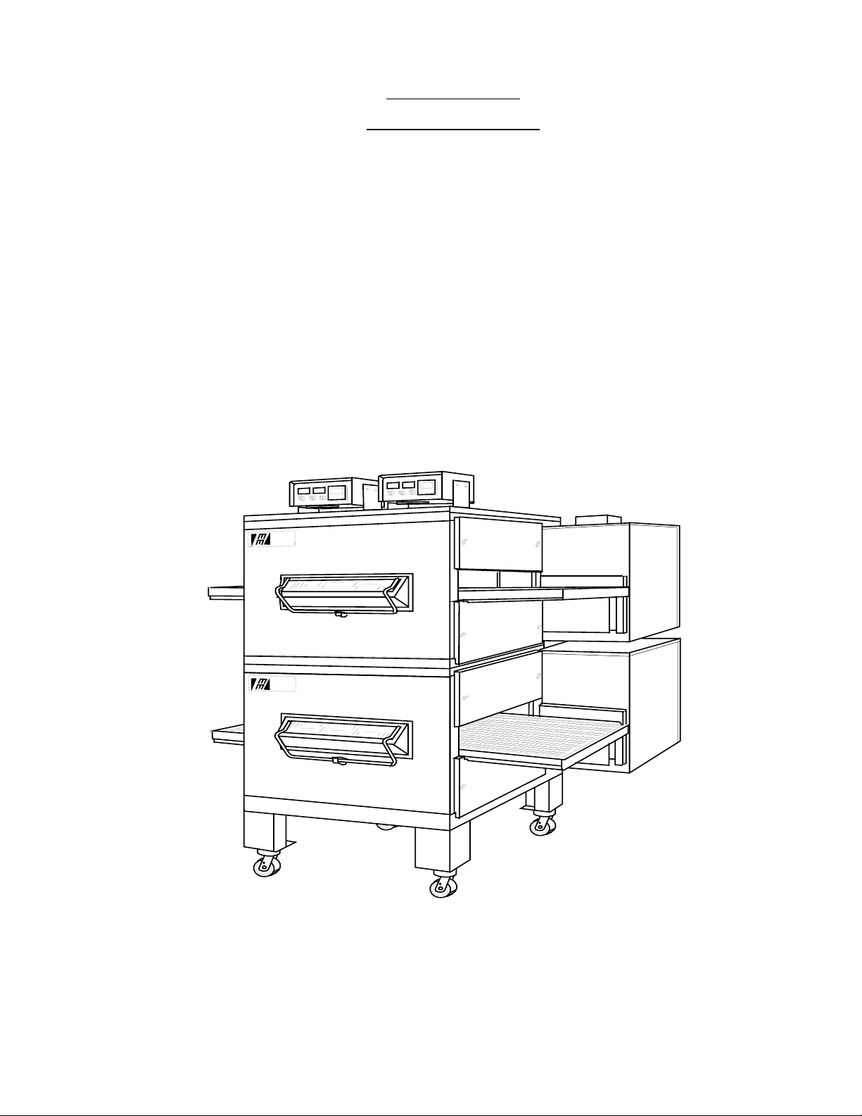
The Middleby™ Series PS200-R68 Ovens may be used
singly or stacked for use as double ovens.
The Series PS200-R68 single oven is mounted on a base
pad with 6" extension legs and casters. A double oven is
stacked and the lower oven is on a base pad with casters.
Middleby
Marshall
The ovens in a double oven operate completely independent of one another. Both ovens use identical controls
and components. One can be serviced while the other is
operating.
The Series PS200-R68 Ovens can be ordered with the
conveyor drive at either the right end or left end of the
oven. Each oven is equipped with a remote control box.
Middleby
Marshall
Figure 1-1. Middleby™ Series PS200-R68 Ovens
1
Page 2

PS200-R68 GAS PS200-R68 ELECTRIC PS224-R68 GAS PS224-R68 ELECTRIC PS220-R68 GAS PS220-R68 ELECTRIC
Conveyor Belt Width 32"(813mm) 32"(813mm) 24"(610mm) 24"(610mm) 20"(508mm) 20"(508mm)
Heating Zone Length 40-1/2"(1028mm) 40-1/2"(1028mm) 40-1/2"(1028mm) 40-1/2"(1028mm) 40-1/2"(1028mm) 40-1/2"(1028mm)
Baking Area Square Feet 9 sq.ft.(0.84sq.m.) 9 sq.ft.(0.84sq.m.) 6.4 sq.ft.(0.59sq.m.) 6.4 sq.ft.(0.59sq.m.) 5.5 sq.ft.(0.51sq.m.) 5.5 sq.ft.(0.51sq.m.)
Overall Dimension 68"(1727mm) L x 68"(1727mm) L x 68"(1727mm) L x 68"(1727mm) L x 68"(1727mm) L x 68"(1727mm) L x
Red Lobster Double Oven 57-3/4"(1467mm) W x 57-3/4"(1467mm) W x 49-3/4"(1264mm) W x 49-3/4"(1264mm) W x 45-3/4"(1162mm) W x 45-3/4"(1162mm) W x
Weight of Single Oven 925 lbs.(419kg) 925 lbs.(419kg) 825 lbs.(374kg) 825 lbs.(374kg) 750 lbs.(340kg) 750 lbs.(340kg)
Shipping Weight of Single Oven 1,100 lbs.(498.3kg) 1,100 lbs.(498.3kg) 1,000 lbs.(453kg) 1,000 lbs.(453kg) 925 lbs.(419kg) 925 lbs.(419kg)
Shipping Cube of Single Oven Approx.132 ft3(3.74 m3) Approx.132 ft3(3.74 m3) Approx.132 ft3(3.74 m3) Approx.132 ft3(3.74 m3) Approx.132 ft3(3.74 m3) Approx.132 ft3(3.74 m3)
Operating Range of Single Oven 120,000 BTU/HR 28kW/HR 100,000 BTU/HR 28kW/HR 100,000 BTU/HR 28kW/HR
Maximum Operating Temperature 550°F(287°C) 550°F(287°C) 550°F(287°C) 550°F(287°C) 550°F(287°C) 550°F(287°C)
Exhaust Vent Size 2" x 3"(50 x 75mm) -- 2" x 3"(50 x 75mm) -- 2" x 3"(50 x 75mm) -Exhaust Flow 80 C.F.M.(2.1m3m) -- 80 C.F.M.(2.1m3m) -- 80 C.F.M.(2.1m3m) -Warm Up Time 10 min. 15 min. 10 min. 15 min. 10 min. 15 min.
Gas Inlet Line Size 3/4"(19mm)ID for each cavity
Minimum Gas Meter Rating 450 cu.ft./hr.(12.74m3h) for 1 to 2 cavities
2
Minimum Gas Pipe Size: Natural 2" (51mm)ID for 1 or 2 ovens or
Propane 1.5" (38mm)ID for 1 to 2 ovens or
Gas Pressure: Natural 6"(152mm) to 14"(356mm) Water Column
Propane 11.5"(292mm) to 14"(356mm) Water Column
Gas Valves 0.75" (19mm)ID full flow gas shut-off valve.
Recirculating Air Blower One blower at 1700 RPM
Jet Air Velocity 3000 F.P.M.(1524cm/sec.)(Average)
Bake Time 2 min. 40 sec. Bake Time minimum
76-3/4"(1949mm) H 76-3/4"(1949mm) H 76-3/4"(1949mm) H 76-3/4"(1949mm) H 76-3/4"(1949mm) H 76-3/4"(1949mm) H
(30,240 kcal) (25,200 kcal) (25,200 kcal)
(35.1 kW/HR) (29.3 kW/HR) (29.3 kW/HR)
Add 180 cu.ft./hr.(5.1m3h)for each additional cavity
2.5" (64mm)ID for 3 or 4 ovens
2"(51mm)ID for 3 or 4 ovens -
(must be dedicated line)
A separate connection and valve must be provided for each cavity.
29 min. 50 sec. Bake Time maximum
SECTION 1
DESCRIPTION
PS200-R68 SERIES OVEN SPECIFICATIONS
Page 3

SERIES PS200-R68
ELECTRICAL SPECIFICATIONS
GAS HEATED OVENS
Main Blower Control Phase Frequency Amperage Poles Wires
& Elements Circuit Draw
Voltage Voltage
208-240V 120V 1 Ph 50/60 Hz 4.1 Amp 3 Pole 4 Wire
(2 hot,1 neut,1 grd)
208V 120V 1 Ph 50/60 Hz 4.1 Amp 2 Pole 3 Wire
Export Transformer (2 hot,1 grd)
200V 120V 1 Ph 50/60 Hz 4.1 Amp 2 Pole 3 Wire
Export Transformer (2 hot,1 grd)
220-240V 120V 1 Ph 50/60 Hz 4.1 Amp 2 Pole 3 Wire
Export Transformer (2 hot,1 grd)
ELECTRIC HEATED OVENS
Main Blower Control Phase Frequency Amperage Poles Wires
& Elements Circuit Draw
Voltage Voltage
208-240V 120V 3 Ph 50/60 Hz 75 Amp 4 Pole 5 Wire
(3 hot, 1 neut, 1 grd)
HEATER AMPERAGE
Voltage kW Amp Average Amps
208 27 70 37 37 37
220 23.5 67 30 30 30
230 25.7 63 31 31 31
240 27 61 33 33 33
220-240V 120V 3 Ph 50/60 Hz 75 Amp 3 Pole 4 Wire
Transformer (3 hot, 1 grd)
HEATER AMPERAGE
Voltage kW Amp Average Amps
220 23.5 67 30 30 30
240 27 61 33 33 33
380V 120V 3 Ph 50/60 Hz 50 Amp 4 Pole 5 Wire
Export Transformer (3 hot, 1 neut, 1 grd)
HEATER AMPERAGE
Voltage kW Amp Average Amps
380 27 38 22 22 22
400-416V 120V 3 Ph 50/60 Hz 50 Amp 4 Pole 5 Wire
Export Transformer (3 hot, 1 neut, 1 grd)
HEATER AMPERAGE
Voltage kW Amp Average Amps
415 27 35 28 28 28
SECTION 1
DESCRIPTION
NOTE
Wiring Diagram is contained at the back of this Manual
and is also located inside of the
machinery compartment.
.
3
Page 4

SECTION 1
DESCRIPTION
II. PRINCIPLE OF AIR FLOW
Air is heated and then pulled through the fan which
pushes the air into the oven plenum and delivers heated
air into the air fingers. The fingers contain an inner plate
and outer plate which columnate the air and evenly
distribute heated air across the conveyor belt on which
the product rides. Air is then pulled back into the blower
and the process continues.
A. Heat Transfer and How It Works
1. Heat constantly moves from a warm object to a cold
object. Heat moves using three different paths which are
conduction, radiation and convection.
Conduction:
tact. The pizza dough in contact with the pan is a good
example of conduction.
Radiation:
heat. Dark objects absorb heat whereas light or shiny
objects reflect more heat. This is the reason that the
This path utilizes surface to surface con-
This path has to do with objects radiating
inside of the Middleby Series PS200-R68 Oven is light in
color to reflect more heat back to the product.
Convection:
of air. It explains why hot air will rise and cooler air
replaces hot air. An industrial application of this principle
is to incorporate a fan to force the hot air movement which
in turn will increase the heat transfer to the product.
The Middleby Series PS200-R68 Oven has a large fan to
move the hot air through the air fingers and onto the
product so the most efficient bake is achieved.
2. Temperature is the intensity of heat at the point which
it is sensed. As discussed above, heat flows by conduction, radiation and convection. The speed at which the
heat flows is determined by the temperature difference
between the oven and the food product. The larger the
difference the faster the heat flows to the item that is
being baked.
This path has to do with moving amounts
Side View
Figure 1-2
Series PS200-R68 Air Flow
4
Page 5

II. PRINCIPLE OF AIR FLOW Continued
SECTION 1
DESCRIPTION
Air Flow From
Plenum Chamber
Outer Plate
High Velocity
Columns of Air to
Product
Air Flow From
Plenum Chamber
Manifold Baffle
Inner Plate
Manifold
Manifold Baffle
Inner Plate
Figure 1-3. Air Fingers Showing Air Passing Through Inner Plate And Outer Plate
Which Forms High Velocity Columns Of Air To The Product.
B. Air Fingers
The Middleby Series PS200-R68 Oven is a conveyorized
hot air oven employing vertical air streams (Figure1-3) to
give uniform and intensive heating. The columnated
vertical streams of hot air provide an exceptional heat
transfer rate and generally bake faster and at lower
temperatures than convection hot air or infrared heating
ovens.
Outer Plate
Manifold
This is accomplished with use of hot air fingers inside the
oven. The oven can accommodate up to 4 bottom air
fingers and 4 top air fingers. Standard PS200-R68 Series
ovens have 4 bottom fingers and 2 top fingers.
5
Page 6

SECTION 1
DESCRIPTION
Cooling
Fan
Conveyor
End Stop
Conveyor
Rear Stop
Middleby
Marshall
Control
Boxes
Removable
Jet Fingers
(Inside
Oven)
Machinery
Compartment
Conveyor
Motor
Front
Window
Middleby
Marshall
Removable End Plugs
Locking
Casters
(Rear Casters
are not locking
casters)
Figure 1-4. Component Location
Removable
Crumb Pans
Removable
Drip Pans
(Inside Oven)
Removable
Conveyor
6
Page 7

SECTION 1
DESCRIPTION
III. COMPONENT FUNCTION
A. Conveyor
The conveyor is driven by a variable speed electric motor
operating through a gear reducer (See Figure 1-5). The
motor speed is controlled by a digital control. The stainless steel wire belt can travel in either direction and at
variable speeds from 3 minutes to 23 minutes.
Conveyor
Drive Motor
Fan
Motor
Should a flame outage occur the control will close the
main gas control valve within 0.8 seconds and attempt to
reignite the pilot.
D. Electric Heaters (Electric Oven Only)
There are six heater elements mounted on the inside of
the rear panel. Each element is connected to a separate
electrical contact which is energized by the temperature
controller.
E. Front Window
The front window is used for viewing items being baked
and provides access to the oven for items which do not
require full bake time, such as sandwiches, cookies,
small items or cheese melting processes.
F. Cooling Fan
A cooling fan is located in the back of the oven. This
cooling fan blows cool air in through the machinery
compartment across the fan motor and conveyor motor
and control cabinet. The air is then exhausted through
the side of the cabinet and also out the back of the oven
compartment. Refer to Figure 1-6.
Main Gas
Control Valve
Figure 1-5. Conveyor Drive Motor
B. Fan
The fan is located at the rear of the oven. This fan forces
heated air through the fingers. The fan switch has two
positions and must be "on" for oven warm up and bake
and for the conveyor to run.
Another cooling fan is located in the bottom of each
control box. Air is drawn in through the louvers in the rear
of the control box and out through the fan. Refer to Figure
1-4.
C. Gas Burner (Gas Oven Only)
With the heat and blower switches ON the gas burner
heats the air as the air enters the main blowers to
maintain the set temperature. The burner flame is ignited
and monitored by a solid state burner control device.
Figure 1-6. Cooling Fan
7
Page 8

SECTION 1
DESCRIPTION
G. Air Fingers
The Air Finger Assemblies are made up of three parts as
follows (See Figure 1-7):
1. Outer Plate - The Outer Plate is the removable cover
with tapered holes, which directs the air stream onto the
product to be baked.
2. Inner Plate -The Inner Plate is vital to forming the
manifold with its holes lined up with outer plate holes.
The inner plate is also manufactured with no rows of
holes. This type of finger is a non-columnating air finger.
3. Manifold - The Manifold is the assembly which slides
on tracks into the oven plenum.
4. Blank Plates- The Blank Plates are installed on the
plenum where air fingers are not required.
columnated air jets. It must be assembled onto the
NOTE: On a PS200-R68 Series Red Lobster oven the 2 upper fingers (M3) have 3 rows of holes in the outer plate
and a non-columnating inner plate. The 4 bottom fingers (M6) have 6 rows of holes completely across the inner and
outer plates.
Manifold
4-1/32" Rear
Opening
No Large Holes,
Perforated Only
UPPER
Inner
Plate
M3RN
Finger
Outer Plate with
3 Rows of Holes
Stamped "UPPER"
UPPER
Full
Blank
RED LOBSTER FINGER CONFIGURATION IN OVEN
FB M3RNFBM3RN
Product Direction (Either Direction)
M6
M6
M6
M6
Finger
M6
5-5/32" Rear
Upper Fingers
Lower Fingers
Large Holes &
Perforated
Opening
Raised Front
(Stamped "UPPER")
Outer Plate
with 6 Rows
of Holes
Inner
Plate
Baffle
Manifold
Figure 1-7. Fingers
8
 Loading...