

Page 1
MiddlebyMiddleby
Middleby
MiddlebyMiddleby
MarshallMarshall
Marshall
MarshallMarshall
A MIDDLEBY COMPANY
owner's
operating
& installation
manual
PS520-Series Gas Ovens: English
November 12, 2008
®
PS520-Series
Model
PS520G
OVENS
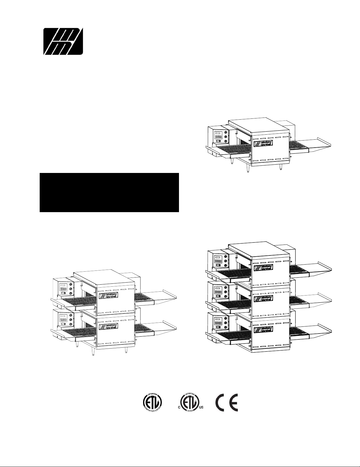
PS520 (Single)
PS520 (Double)
©2006 Middleby Marshall Inc.
PS520 (Triple)
Part No. 59223 Rev. B
Price $30.00
P: 11/08
Page 2

NOTICE:
This Owner's Operating and Installation Manual should be given to the user. The operator of the oven should
be familiar with the functions and operation of the oven.
This manual must be kept in a prominent, easily reachable location near the oven.
Ovens are shipped from the factory configured for use with natural gas. If permitted by local, national and
international codes, at the time of installation the oven may be converted to propane gas operation. This
conversion requires the use of at Gas Conversion Kit that is supplied with the oven. For CE-approved ovens,
the conversion is described in the Installation section of this Manual. For domestic and standard export ovens,
instructions are included in the Gas Conversion Kit.
It is suggested to obtain a service contract with a Middleby Marshall Authorized Service Agent.
WARNING
POST, IN A PROMINENT LOCATION, THE EMERGENCY TELEPHONE NUMBER OF YOUR LOCAL
GAS SUPPLIER AND INSTRUCTIONS TO BE FOLLOWED IN THE EVENT YOU SMELL GAS.
Instructions to be followed in the event the user smells gas shall be obtained by consulting the local gas
supplier. If the smell of gas is detected, immediately call the emergency phone number of your local Gas
Company. They will have personnel and provisions available to correct the problem.
WARNING
FOR YOUR SAFETY, DO NOT STORE OR USE
GASOLINE OR OTHER FLAMMABLE VAPORS AND
LIQUIDS IN THE VICINITY OF THIS OR ANY OTHER
APPLIANCE.
WARNING
Improper installation, adjustment, alteration, service, or
maintenance can cause property damage, injury, or
death. Read the installation, operation, and maintenance
instructions thoroughly before installing or servicing this
equipment.
NOTICE
The warranty is
demonstrated under the supervision of a factory-authorized installer.
Contact your authorized Service Agency to perform maintenance and
repairs. A Service Agency Directory is supplied with your oven.
Using any parts other than genuine Middleby Marshall factory-manufactured
parts relieves the manufacturer of all warranty and liability.
Middleby Marshall (Manufacturer) reserves the right to
NOT VALID
unless the oven is installed, started, and
NOTICE
NOTICE
NOTICE
change specifications at any time.
KEEP THIS MANUAL IN A VISIBLE LOCATION NEAR THE OVEN
FOR FUTURE REFERENCE.
ii
Page 3

Model No.
Modéle No.
Serial No.
Serié No.
Installation Date
Date d'installation
MIDDLEBY MARSHALL
NO QUIBBLE LIMITED WARRANTY
(U.S.A. ONLY)
MIDDLEBY MARSHALL, HEREINAFTER REFERRED TO AS
“THE SELLER”, WARRANTS EQUIPMENT MANUFACTURED
BY IT TO BE FREE FROM DEFECTS IN MATERIAL AND
WORKMANSHIP FOR WHICH IT IS RESPONSIBLE. THE
SELLER’S OBLIGATION UNDER THIS WARRANTY SHALL
BE LIMITED TO REPLACING OR REPAIRING, AT SELLER’S
OPTION, WITHOUT CHARGE, ANY PART FOUND TO BE
DEFECTIVE AND ANY LABOR AND MATERIAL EXPENSE
INCURRED BY SELLER IN REPAIRING OR REPLACING
SUCH PART. SUCH WARRANTY SHALL BE LIMITED TO
THE ORIGINAL PURCHASER ONLY AND SHALL BE EFFECTIVE FOR A PERIOD OF ONE YEAR FROM DATE OF ORIGINAL INSTALLATION, OR 18 MONTHS FROM DATE OF PURCHASE, WHICHEVER IS EARLIER, PROVIDED THAT TERMS
OF PAYMENT HAVE BEEN FULLY MET.
This warranty is valid only if the equipment is installed, started,
and demonstrated under the supervision of a factory-authorized installer.
Normal maintenance functions, including lubrication, cleaning, or customer abuse, are not covered by this
warranty
Seller shall be responsible only for repairs or replacements
of defective parts performed by Seller’s authorized service
personnel. Authorized service agencies are located in principal cities throughout the contiguous United States, Alaska,
and Hawaii. This warranty is valid in the 50 United States
and is void elsewhere unless the product is purchased
through Middleby International with warranty included.
.
The foregoing warranty is exclusive and in lieu of all other
warranties, expressed or implied. There are no implied
warranties of merchantability or of fitness for a particular purpose.
The foregoing shall be Seller’s sole and exclusive obligation
and Buyer’s sole and exclusive remedy for any action, including breach of contract or negligence. In no event shall
Seller be liable for a sum in excess of the purchase price of
the item. Seller shall not be liable for any prospective or lost
profits of Buyer.
This warranty is effective on Middleby Marshall equipment sold on, or after, February 15, 1995.
no quibble
MIDDLEBY MARSHALL INC.
OVEN LIMITED WARRANTY
(Non U.S.A.)
The Seller warrants equipment manufactured by it to be free from
defects in material and workmanship for which it is responsible. The
Seller’s obligation under this warranty shall be limited to replacing or
repairing, at Seller’s option, without charge, F.O.B. Seller’s factory,
any part found to be defective and any labor and material expense
incurred by Seller in repairing or replacing such part. Such warranty
is limited to a period of one year from date of original installation or
15 months from date of shipment from Seller’s factory, whichever is
earlier, provided that terms of payment have been fully met. All labor
shall be performed during regular working hours. Overtime premium
will be charged to the Buyer.
This warranty is not valid unless equipment is installed, started,
and demonstrated under the supervision of a factory-authorized installer.
Normal maintenance functions, including lubrication, adjustment of
airflow, thermostats, door mechanisms, microswitches, burners
and pilot burners, and replacement of light bulbs, fuses and indicating lights, are not covered by warranty.
Any repairs or replacements of defective parts shall be performed by
Seller’s authorized service personnel. Seller shall not be responsible for any costs incurred if the work is performed by other than
Seller’s authorized service personnel.
When returning any part under warranty, the part must be intact and
complete, without evidence of misuse or abuse, freight prepaid.
Seller shall not be liable for consequential damages of any kind
which occur during the course of installation of equipment, or which
result from the use or misuse by Buyer, its employees or others of
the equipment supplied hereunder, and Buyer’s sole and exclusive
remedy against Seller for any breach of the foregoing warranty or
otherwise shall be for the repair or replacement of the equipment or
parts thereof affected by such breach.
The foregoing warranty shall be valid and binding upon Seller if and
only if Buyer loads, operates and maintains the equipment supplied
hereunder in accordance with the instruction manual provided to
Buyer. Seller does not guarantee the process of manufacture by
Buyer or the quality of product to be produced by the equipment
supplied hereunder and Seller shall not be liable for any prospective
or lost profits of Buyer.
THE FOREGOING WARRANTY IS EXCLUSIVE AND IN LIEU OF
ALL OTHER EXPRESS AND IMPLIED WARRANTIES WHATSOEVER. SPECIFICALLY THERE ARE NO IMPLIED WARRANTIES
OF MERCHANTABILITY OR OF FITNESS FOR A PARTICULAR
PURPOSE.
The foregoing shall be Seller’s sole and exclusive obligation and
Buyer’s sole and exclusive remedy for any action, whether in breach
of contract or negligence. In no event shall seller be liable for a sum
in excess of the purchase price of the item.
© 2003 - Middleby Marshall, A Middleby Company.
The Middleby Marshall logo is a registered trademark of Middleby Marshall, A Middleby Company.
Middleby Marshall Inc. • 1400 Toastmaster Drive • Elgin, Illinois 60120-9272 U.S.A. • (847) 741-3300 • FAX: (847) 741 4406
iii
Page 4

TABLE OF CONTENTS
Page
SECTION 1
I. MODEL IDENTIFICATION .............................................. 1
SERIES PS520 GAS SPECIFICATIONS ............................ 2
II. COMPONENT FUNCTION ............................................. 4
A. Conveyor Motor and Conveyor Belt ........................ 4
B. Blower Fan ................................................................. 4
C. Gas Burner ................................................................ 4
D. Cooling Fan ................................................................ 4
E. Air Fingers and Blank Plates - See Figure 1-9 ........ 4
SECTION 2
I. UNLOADING ................................................................... 8
PARTS LIST FOR SERIES PS520 GAS OVEN
INSTALLATION KIT .................................................... 8
UTILITY ROUGH-IN DIMENSIONS AND POSITIONING
FOR PS520-SERIES OVENS .................................... 13
CIRCUIT BREAKER ..................................................... 13
ELECTRICAL SPECIFICATIONS ................................. 13
ELECTRICAL RATING ................................................. 13
SUPPLY WIRE .............................................................. 13
SUGGESTED ................................................................ 13
II. VENTILATION GUIDELINES ........................................ 13
III. ELECTRICAL CONNECTION INFORMATION FOR
PS520-SERIES OVENS. ........................................... 14
IV. ELECTRIC SUPPLY FOR GAS HEATED OVENS ..... 14
V. GAS SUPPLY .............................................................. 15
SECTION 3 INSTALLATION
I. CONTROL FUNCTIONS ................................................ 19
II. COMPONENT INFORMATION AND LOCATION ......... 20
A. Door Safety Switch .................................................. 20
B. Blower Switch .......................................................... 20
C. Heat Switch .............................................................. 20
D. Temperature Controller .......................................... 20
E. Conveyor ................................................................. 21
MEASURING CONVEYOR SPEED. ............................. 21
TABLE OF CONTENTS
(Continued)
Page
III. STEP-BY-STEP OPERATION ....................................... 22
A. Startup Procedures ................................................. 22
Daily Startup ................................................................. 22
Power Failure ............................................................... 22
B. Shutdown Procedure ............................................... 22
IV. NORMAL OPERATION - STEP-BY-STEP ................... 24
A.Daily Startup Procedure ........................................... 24
B. Daily Shutdown Procedure ...................................... 24
V. QUICK REFERENCE: TROUBLESHOOTING ............ 26
SECTION 4 MAINTENANCE
I. MAINTENANCE - DAILY ............................................ 28
A. Exterior ..................................................................... 28
B. Cooling Fan ............................................................... 2 8
C. Conveyor Belt .......................................................... 2 8
D. Crumb Pans ............................................................. 28
II. MAINTENANCE - MONTHLY ....................................... 29
A. Removing Conveyor From Oven For Cleaning ..... 29
B. Air Fingers Disassembly For Cleaning .................. 31
C. Reassembly of Air Fingers ..................................... 32
D. Reinstall End Plugs ................................................. 35
E. Conveyor Reassembly Into Oven .......................... 36
F. Checking Conveyor Belt Tension ........................... 36
G. Conveyor Belt Link Removal ................................. 37
H. Attaching Drive Chain ............................................. 3 8
III. MAINTENANCE - EVERY 3 MONTHS ......................... 39
A. Electrical Terminals ................................................ 39
B. Ventilation ................................................................ 39
IV. MAINTENANCE - EVERY 6 MONTHS ........................ 39
PS520-SERIES GAS OVEN KEY SPARE
PARTS ....................................................................... 40
KEY SPARE PARTS KIT ............................................... 40
SECTION 5 TROUBLESHOOTING
Troubleshooting Charts ...................................................... 4 1
SECTION 6 ELECTRICAL SCHEMATICS
Wiring Diagram, G208-240V 50/60 GO, PS520 ............... 4 3
iv
NOTE
Wiring Diagrams are in Section 6 of this Manual.
The diagram for each oven is also on the lower
inner surface of its Control Console.
Page 5
SECTION 1
DESCRIPTION
I. MODEL IDENTIFICATION
The Middleby Marshall PS520-Series may be used either
as a single oven or stacked for use as double or triple
ovens.
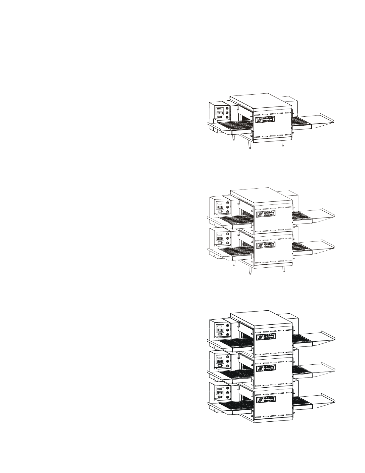
A single PS520-Series Oven (Figure 1-1) is mounted on a
base pad with legs. A double oven (Figure 1-2) consists of
two,
stacked,
consists of three stacked single ovens. The lower oven is
mounted on a base pad with stacking pins.
On a double or triple oven, the ovens operate independently. All ovens use identical controls and components.
One oven can be cleaned or serviced, while the others are
operating.
single ovens. A triple oven (Figure 1-3)
SECTION 1
DESCRIPTION
Figure 1-1. Single PS520 Oven
Figure 1-2. Double PS520 Oven
Figure 1-3. Triple PS520 Oven
1
Page 6

SECTION 1
DESCRIPTION
PS520 SERIES OVEN SPECIFICATIONS
Conveyor Belt Width 18.00″ (457mm)
Heating Zone Length 20.00″ (5098mm)
Baking Area Square Feet 2.5 sq. ft. (0.23 sq. m.)
Overall Dimension – Standard Single Oven w/Legs 42.00″ (1067mm) L ×
Overall Dimension – Double Oven 42.00″ (1067mm) L ×
Overall Dimension – Triple Oven 42.00″ (1067mm) L x
Weight of Single Oven 250 lb (93.3kg)
Shipping Weight 325 lb (121.3kg)
Shipping Cube 22.1 ft3 (0.62 m3)
Operating Range 8.3 kW/hr
BTU's – Natural or Propane Gas 40,000 BTU/HR
Gas Input – Natural or Propane Gas 1/2″ NPT
Maximum Operating Temperature 600°F (316°C)
Warm-up Time 20 min.
Belt Speed Limits 1-10 minutes
35.21″ (894mm) W ×
21.10″ (536mm) H ×
35.21″ (894mm) W ×
36.64″ (931mm) H x
35.21″ (894mm) W ×
48.19″ (1224mm) H ×
SERIES PS520 ELECTRICAL SPECIFICATIONS
Main Blower & Control Circuit Phase Frequency Amperage Poles Wires
Elements Voltage Voltage Draw
208-240V 208-240V 1 Ph 50/60 Hz 1.5 Amp 2 Pole 3 Wire
GAS ORIFICE AND PRESSURE SPECIFICATIONS (PER OVEN CAVITY) - DOMESTIC AND STANDARD EXPORT OVENS
Gas Type Main Orifice I.D. Supply (Inlet) Pressure Pressure
Natural 0.082” (2.08mm, #45 drill) 6-12” W.C. (14.9-29.9mbar) * 3.5” W.C. (8.72mbar)
Propane 0.057” (1.45mm, #46 drill) 11-14” W.C. (27.4-34.9mbar) * 7” W.C. (17.44mbar)
* The gas supply pressures and orifice sizes shown are for ovens installed in North America. The required gas supply pressures and orifice
sizes of ovens installed in other locations are dependent on the local gas type and on all applicable local codes.
Orifice (Manifold)
GAS ORIFICE AND PRESSURE SPECIFICATIONS (PER OVEN CAVITY) - CE OVENS
Supply (Inlet) Pressure
Gas Orifice DK,FI DE BE,FR FI,DE,NL ES,UK (Manifold) Heat
Main UK,CH,IT,AT, SE,CH,AT,DK, BE,IE,IT,PT, Orifice Rated
Type dia.
G20 2.3749 20 20 20 -- -- 11.21 22.36
mm mbar mbar mbar mbar kW-hr.
G25 2.3749 -- -- -- -- - - 16.19 22.36
mm mbar kW-hr.
G30 1.3970 -- -- -- 29 or 50 28-30, 37 26.2 22.59
mm mbar or 50 mbar mbar kW-hr.
IT,PT,ES,SE,
I
2H
I
2E
I
2E+
I
3B/P
I
3+
Pressure Input
(2 hot, 1 grd)
NOTE
Wiring Diagrams are contained in Section 6 of this Manual
and are also located inside the oven at the
bottom of the Control Panel.
Additional electrical information is provided on the oven's serial plate.
This Manual Must Be Kept For Future Reference.
2
Page 7
II. COMPONENT FUNCTION (Figure 1-4)
SECTION 1
DESCRIPTION
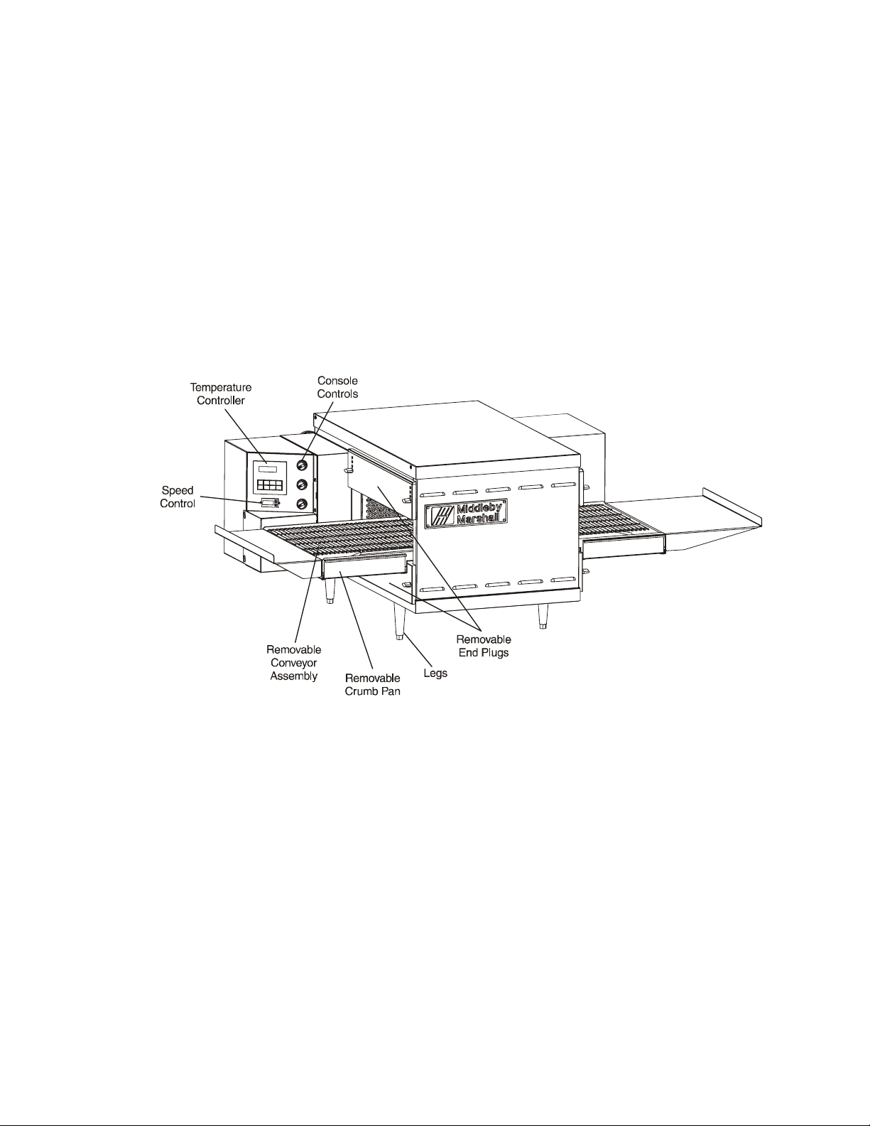
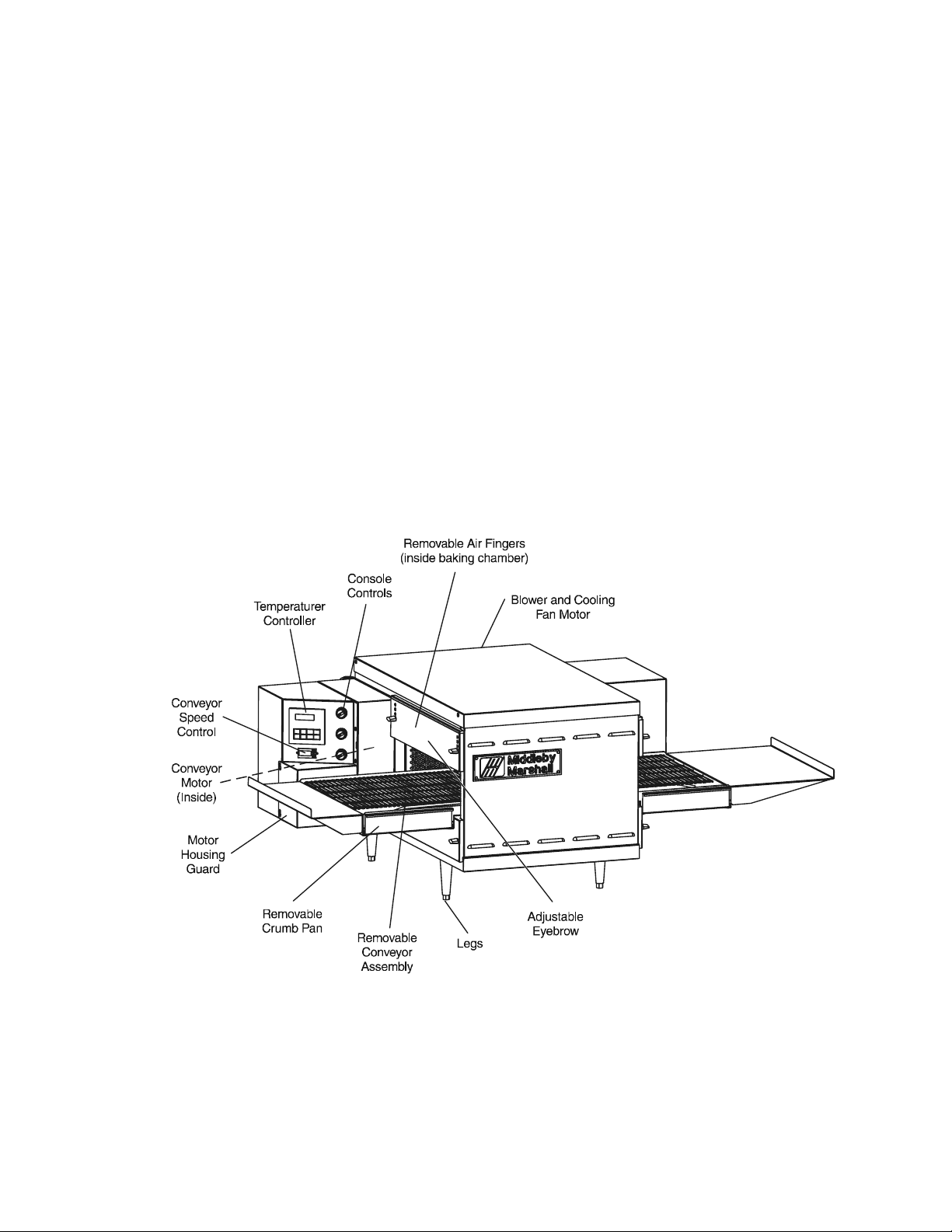
Figure 1-4. PS520-Series Oven Components Locations
3
Page 8
SECTION 1
DESCRIPTION
II. COMPONENT FUNCTION
A. Conveyor Motor and Conveyor Belt
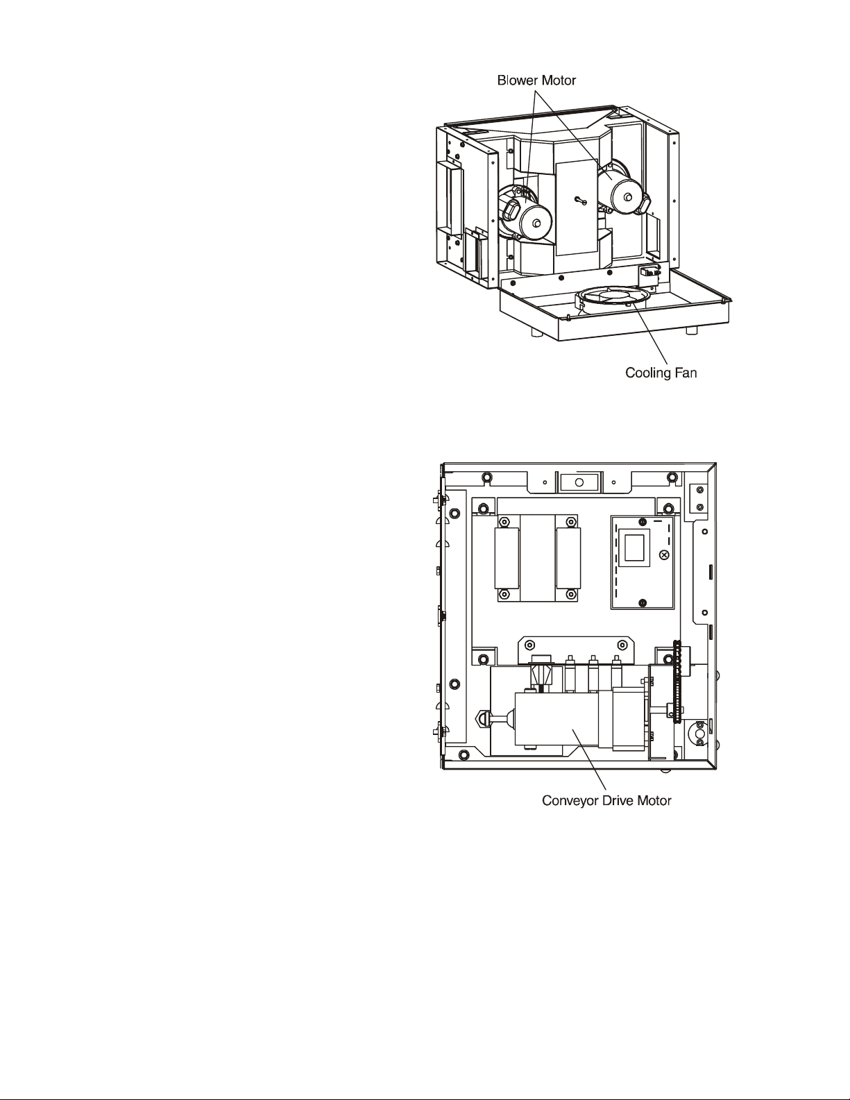
The conveyor belt is driven by a variable-speed electric
motor (Figure 1-5) operating through a gear reducer. The
motor speed is controlled by a digital control. The stainless-steel wire belt can travel in either direction at variable
rates ranging from 3 minutes to 30 minutes; this is the time
that a product can take to pass through the oven.
B. Blower Fan
The blower fans are located at the rear of the oven. These
blowers force heated air through the air fingers. The
BLOWER switch must be set to “ON” or “I” for oven
warmup and baking.
C. Gas Burner
The gas burner is located inside the rear panel and is
controlled by the temperature controller.
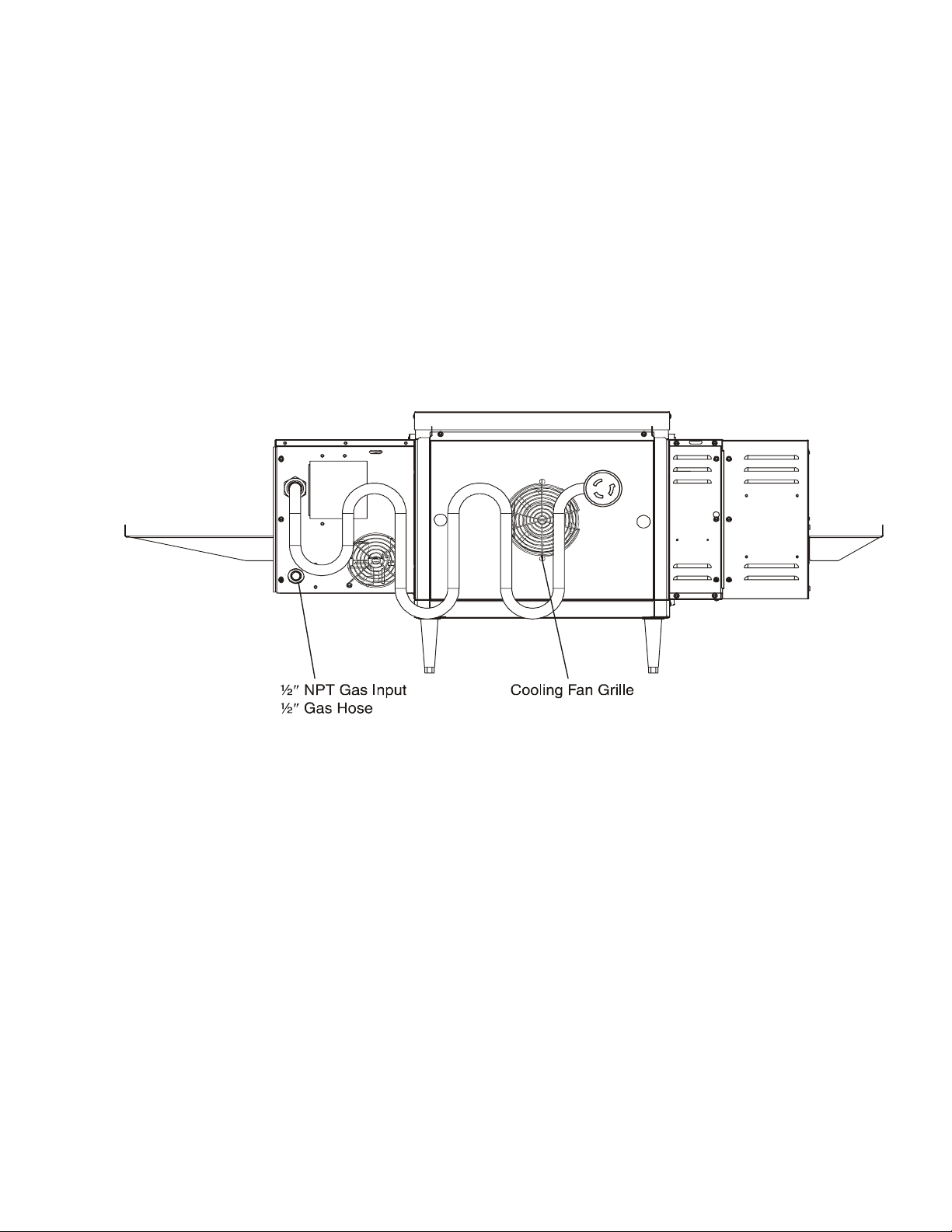
D. Cooling Fan — See Figure 1-5 and Figure 1-6
The cooling fan is located in the back of the oven. The
cooling fan draws air through its grille, blowing it through
the blower motor compartment and the control compartments into the oven top and exhausted out the front
louvers.
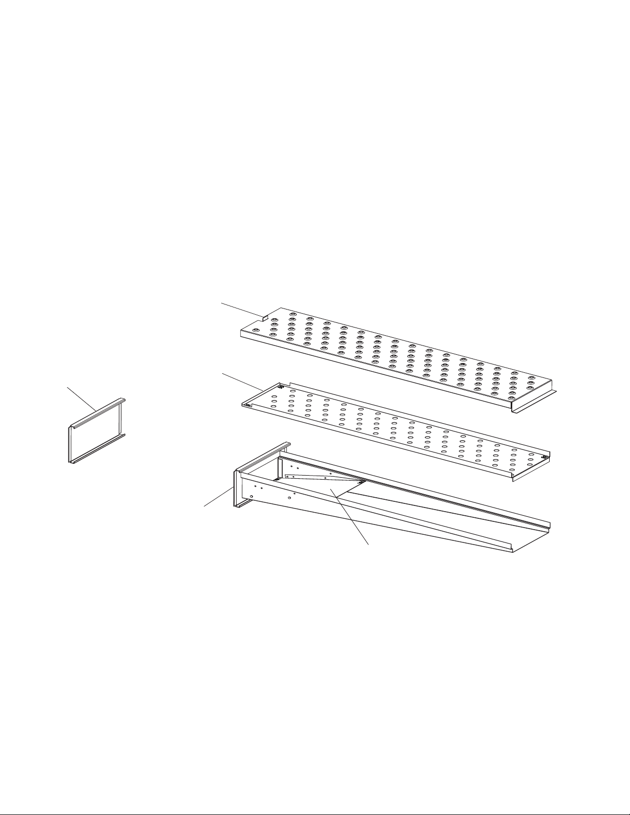
E. Air Fingers and Blank Plates - See Figure 1-7
E1. Air Fingers
An Air Finger Assembly is made up of three parts:
1. Outer Plate - The Outer Plate is the removable covering
with tapered holes, which direct the air stream onto the
product being baked.
2. Inner Plate -The perforated Inner Plate is vital in forming
the unique air jets. It must be assembled into the manifold
with its holes aligned with the holes of the outer plate.
3. Manifold - The Manifold is the assembly which slides
on tracks into the oven plenum.
Blower Assembly
Right Control Box
Figure 1-5. Machinery Compartment
Components
4
Page 9
SECTION 1
DESCRIPTION
Figure 1-6. Cooling Fan
5
Page 10
SECTION 1
DESCRIPTION
Half Blank Plate
F2. Blank Plates
1. Blank Plates- The Blank Plates are available to install
on the plenum where an air finger is not required.
Outer Plate
Blank Plate
Inner Plate
Finger
Manifold
Assembly
Baffle
Figure 1-7. Blank Plates (two sizes) and an Air Finger.
6
Page 11
SECTION 2
SECTION 2
INSTALLATION
INSTALLATION
WARNING - For gas ovens, after any conversions, readjustments, or service work on the oven:
• Perform a gas leak test.
• Test for correct air supply.
• Test for proper combustion and gas supply.
• Check that the ventilation system is in operation.
WARNING
Keep the appliance area free and clear of combustibles.
WARNING
The oven must be installed on an even (level) non-flammable flooring and any adjacent walls must
be non-flammable. Recommended minimum clearances are specified in the Description section of
this Manual.
WARNING
Do not obstruct the flow of combustion and ventilation air to and from your oven. There must be no
obstructions around or underneath the oven. Constructional changes to the area where the oven is
installed shall not affect the air supply to the oven.
CAUTION
For additional installation information, contact your local Authorized Service Agent.
NOTE
There must be adequate clearance between the oven and combustible construction. Clearance
must also be provided for servicing and for proper operation.
NOTE
An electrical wiring diagram for the oven is located inside the machinery compartment.
NOTE
All aspects of the oven installation, including placement, utility connections, and ventilation requirements,
must conform with any applicable local, national, or international codes. These codes supersede the
requirements and guidelines provided in this manual.
NOTE
In the USA, the oven installation must conform with local codes. In the absence of local codes, gas oven
installations must conform with the National Fuel Gas Code, ANSI Z223.1. Installed ovens must be
electrically grounded in accordance with local codes, or in the absence of local codes, with the National
Electrical Code (NEC), or ANSI/NFPA70.
NOTE
In Canada, the oven installation must conform with local codes. In the absence of local codes, gas oven
installations must conform with the Natural Gas Installation Code, CAN/CGA-B149.1, or the Propane Gas
Installation Code, CAN/CGA-B149.2, as applicable. Installed ovens must be electrically grounded in
accordance with local codes, or in the absence of local codes, with the Canadian Electrical Code CSA C22.2.
NOTE
In Australia, the oven installation must conform with any requirements of the appropriate statutory authority.
Gas oven installtions must conform with AGA Codes AG311 and AG601.
NOTE
In CE countries, all aspects of the gas supply connection must comply with current IEC/CEE requirements and
with all applicable local, national, and international codes. In addition, four casters are provided to allow the oven
to be more easily moved to the installation location. These casters are intended to simplify pre-installation
movement only, and are NOT suitable for use as part of a CE oven installation. During the installation procedure,
the casters MUST be removed, so that the oven can be supported by the supplied 152mm adjustable legs.
7
Page 12
SECTION 2
INSTALLATION
NOTE: The oven, when installed, must be electrically
grounded in accordance with local codes, or in the absence of local codes, with the National Electrical Code
(NEC), or ANSI/NFPA70.
NOTE
There must be adequate clearance between
the oven and any adjacent combustible construction. Clearance must also be provided
for servicing and for operation.
CAUTION
It is recommended that the oven be placed under
a ventilation hood for adequate air supply and
ventilation.
CAUTION
Do not obstruct the flow of ventilation air to and
from your oven. Do not obstruct the fan holes in
the rear of the unit.
I. UNLOADING
Your Middleby Marshall PS520-Series Oven is shipped
partially assembled. It will arrive in a carton on a crate.
Carton size for a PS520-Series Oven is:
44-1/4″ (1124mm) Long ×
37-1/2″ (953mm) Wide ×
23″ (584mm) High ×
The crate and carton must be examined before signing the
Bill of Lading. Report any visible damage to the transport
company, and check for the proper number of crates. If
apparent damage is found, make arrangements to file a
claim against the carrier. Surface Interstate Commerce
Regulations (U.S.A.) require that the claim must be
initiated by the consignee within 10 days from the date that
the shipment is received.
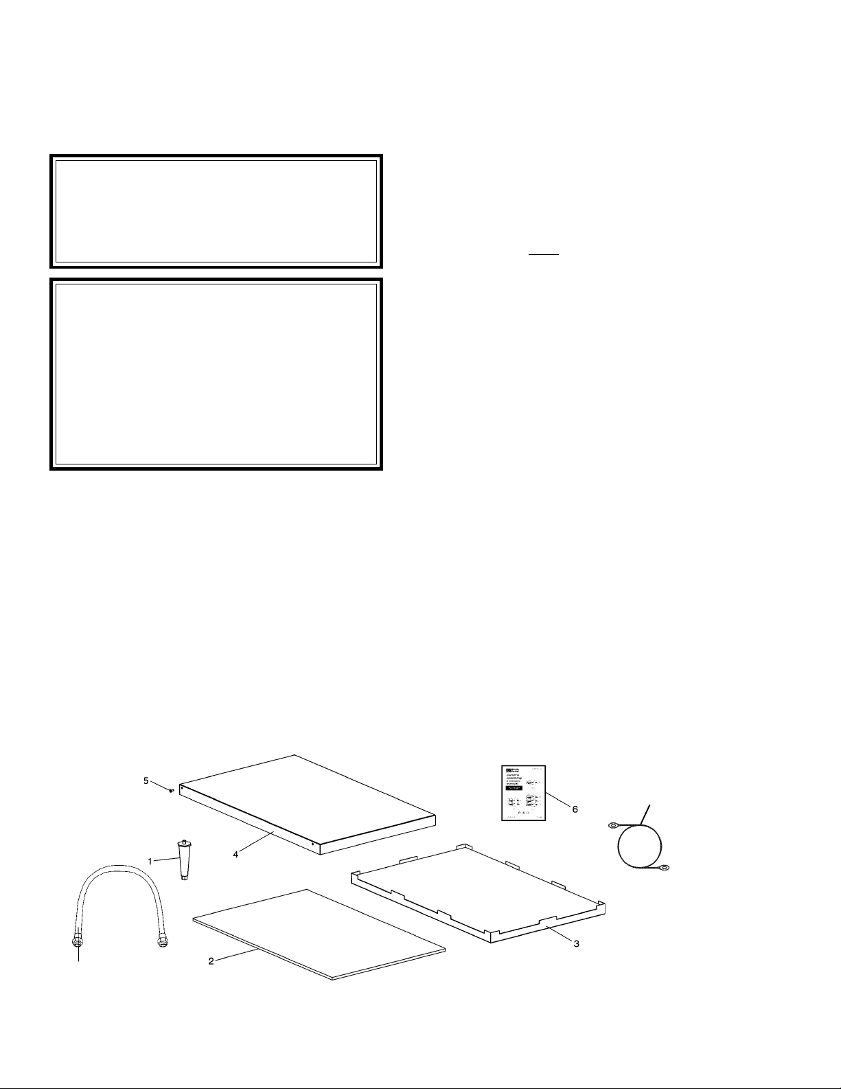
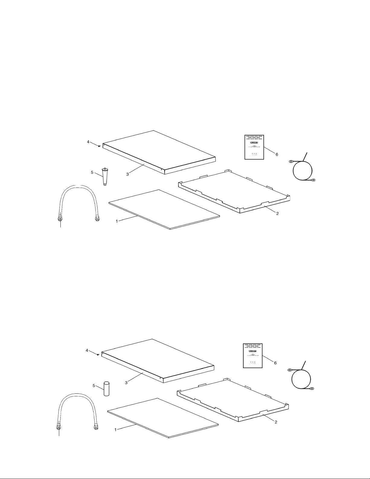
PARTS LIST FOR SERIES PS520 GAS OVEN
INSTALLATION KIT
Single Stack Oven
ITEM
NO. QTY PART NO. DESCRIPTION
1 4 3101908 LEG 4″ AD FT
2 2 48392 INSULATION BOTTOM TRAY
3 1 48394 BOTTOM TRAY WELDMENT
4 1 48396 TOP COVER
5 4 51387 SCREW MSSLT THREAD 8-32 × 1/2, 18-8
6 1 59223 OWNER'S OPERATING & INSTALLATION MANUAL
7 1 22450-0228 GAS HOSE RESTRAINT CABLE
8 1 22361-0001 GAS HOSE
P/N 59182
7
8
Figure 2-1. PS520-Series Gas Oven Installation Parts
8
Page 13
INSTALLATION
PARTS LIST FOR SERIES PS520 Gas OVEN
INSTALLATION KIT
Double Stack Oven
ITEM
NO. QTY PART NO. DESCRIPTION
1 2 48392 INSULATION BOTTOM TRAY
2 1 48394 BOTTOM TRAY WELDMENT
3 1 48396 TOP COVER
4 4 51387 SCREW MSSLT THREAD 8-32 × 1/2, 18-8
5 4 3101908 LEG 4″ AD FT
6 1 59223 OWNER'S OPERATING & INSTALLATION MANUAL
7 1 22450-0228 GAS HOSE RESTRAINT CABLE
8 2 22361-0001 GAS HOSE
P/N 59183
SECTION 2
7
8
PARTS LIST FOR SERIES PS520 Gas OVEN
INSTALLATION KIT
Triple Stack Oven
ITEM
NO. QTY PART NO. DESCRIPTION
1 2 48392 INSULATION BOTTOM TRAY
2 1 48394 BOTTOM TRAY WELDMENT
3 1 48396 TOP COVER
4 4 51387 SCREW MSSLT THREAD 8-32 × 1/2, 18-8
5 4 M3828 PIN, ALIGNMENT
6 1 59223 OWNER'S OPERATING & INSTALLATION MANUAL
7 1 22450-0228 GAS HOSE RESTRAINT CABLE
8 3 22361-0001 GAS HOSE
P/N 59184
7
8
Figure 2-1 (continued). PS520-Series Gas Oven Installation Parts
9
Page 14
SECTION 2
INSTALLATION
1
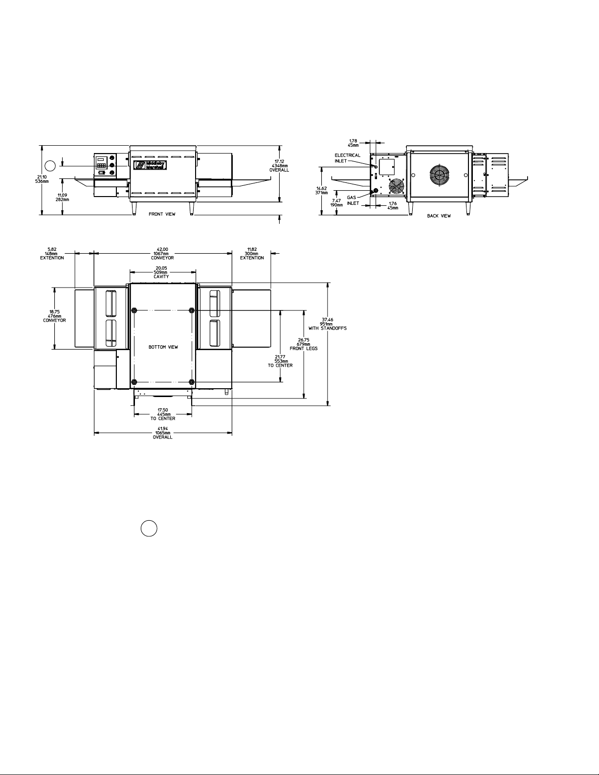
Figure 2-5. MODEL PS520 SINGLE OVEN DIMENSIONS
4.00
101.6mm
The Opening Height is Adjustable from 2-1/4 inch minimum
1
to 3-3/4 inch maximum in 1/2 inch increments.
10
Page 15
SECTION 2
INSTALLATION
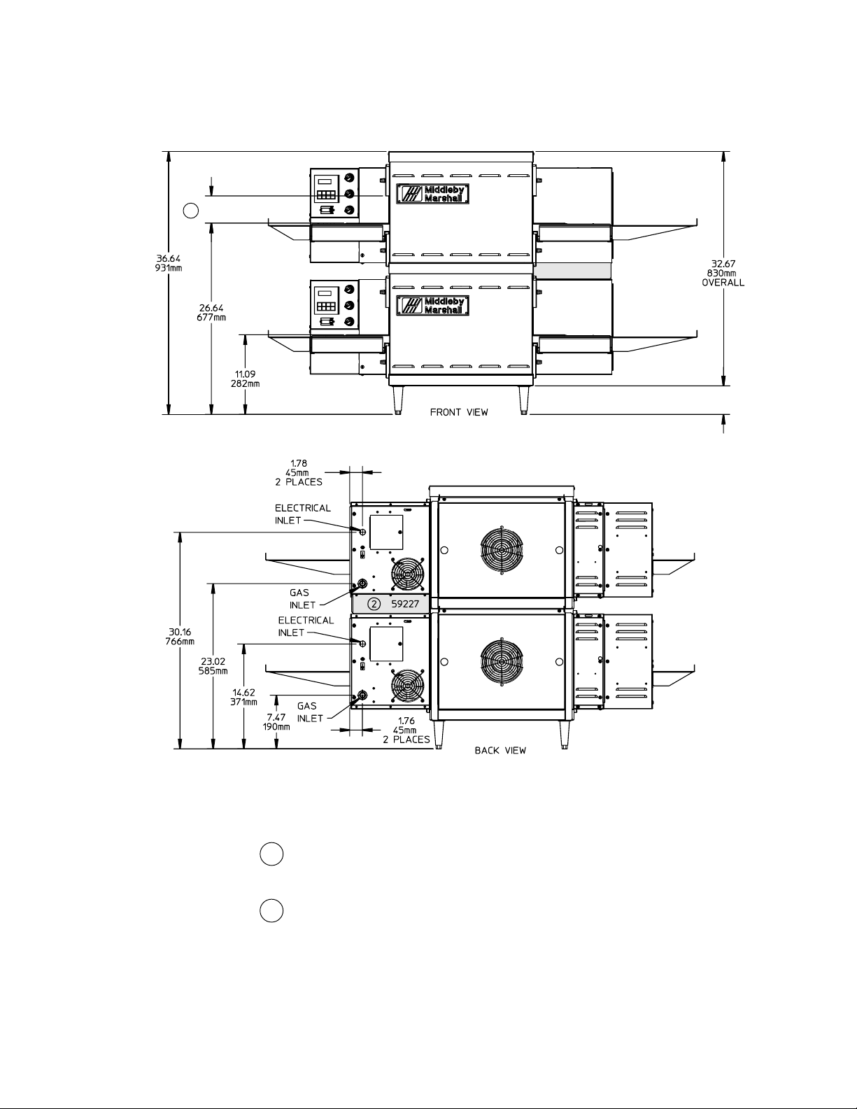
Figure 2-6. MODEL PS520 DOUBLE OVEN DIMENSIONS
1
4.00
101.6mm
The Opening Height is Adjustable from 2-1/4 inch minimum
1
to 3-3/4 inch maximum in 1/2 inch increments.
2
P/N 59927 is shown in its correct installed position.
11
Page 16
SECTION 2
INSTALLATION
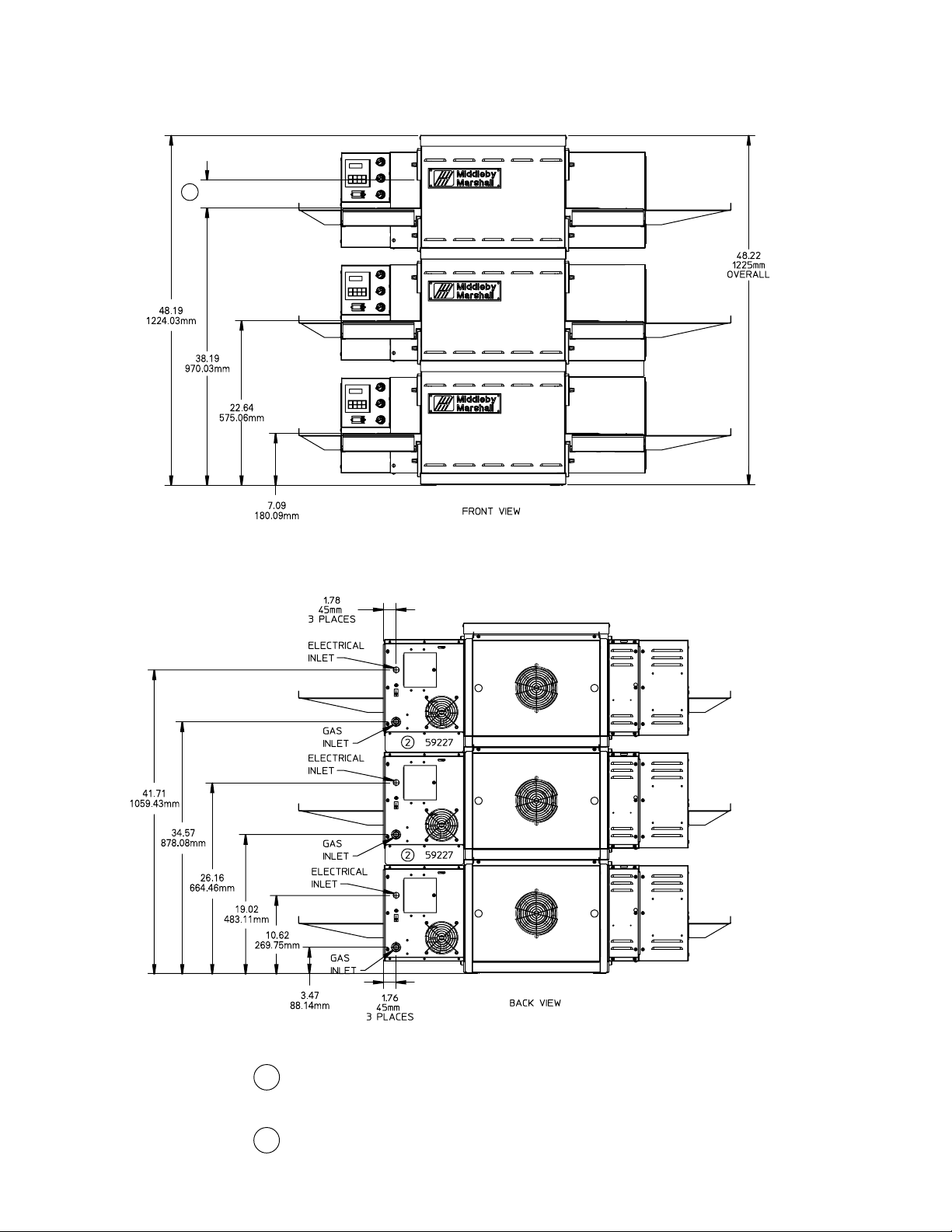
Figure 2-7. MODEL 520 TRIPLE OVEN DIMENSIONS
1
The Opening Height is Adjustable from 2-1/4 inch minimum
1
to 3-3/4 inch maximum in 1/2 inch increments.
2
P/N 59927 is shown in its correct installed position.
12
Page 17
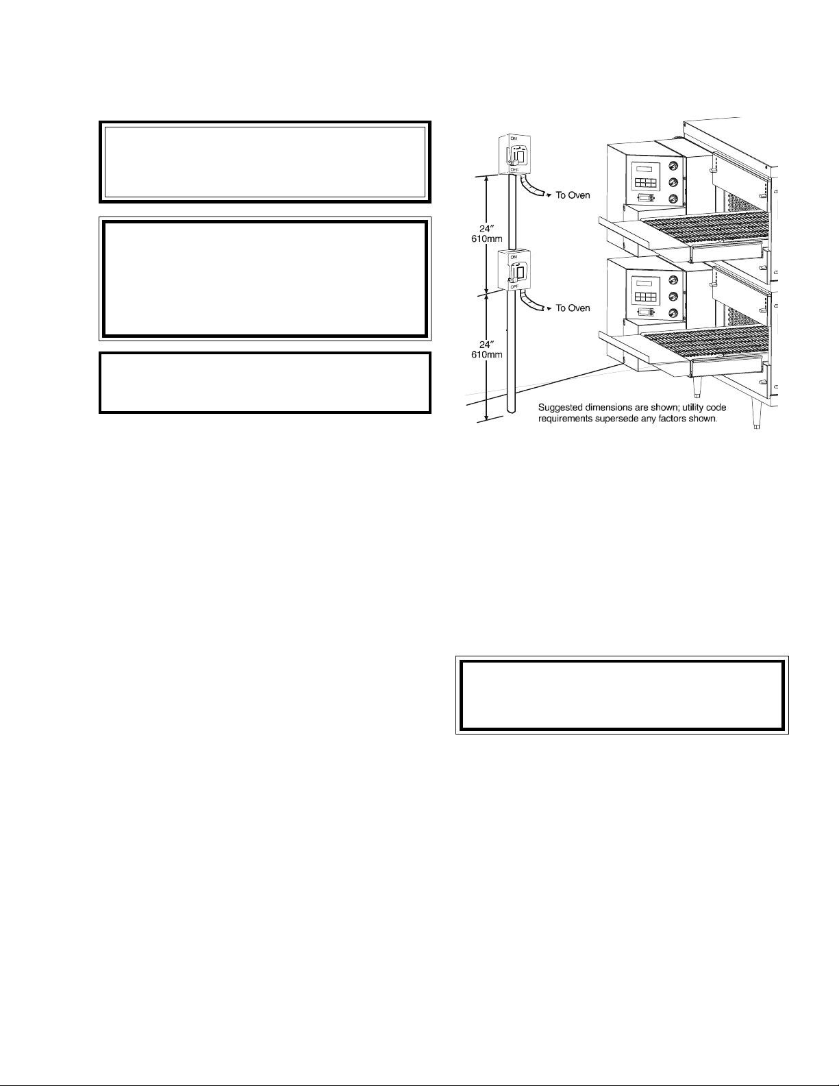
UTILITY ROUGH-IN DIMENSIONS AND POSITIONING
FOR PS520-SERIES OVENS
WARNING
DO NOT USE CONDUIT OR GAS LINE
FOR GROUND CONNECTION.
CAUTION
IT IS RECOMMENDED THAT THE OVEN
BE PLACED UNDER A VENTILATION
HOOD FOR ADEQUATE AIR SUPPLY
AND VENTILATION.
ELECTRIC SUPPLY TO BE
PROVIDED BY CUSTOMER
SECTION 2
INSTALLATION
CIRCUIT BREAKER
Separate circuit breaker with lockout/tagout electrical
shutoff for each oven. Wire each oven separately.
15A Amp circuit breaker for 208-240V.
ELECTRICAL SPECIFICATIONS
DOMESTIC: 208V main blower motors, 1 Ph, 1.5 Amp
draw, 50/60 Hz, 208-240V control circuit, 2 pole, 3 wire
system per oven (2 hot, 1 grd).
Do
NOT
use conduit for ground.
or
DOMESTIC or EXPORT: 240V main blower motors, 1 Ph,
1.5 Amp draw, 50/60 Hz, 208-240V control circuit, 2 pole,
3 wire system per oven (2 hot, 1 grd).
230V main blower motors, 1 Ph, 1.5 Amp draw, 50/60 Hz,
208-240V control circuit, 2 pole, 3 wire system per oven
(2 hot, 1 grd).
Do
NOT
use conduit for ground.
Figure 2-9. Typical PS520-Series Oven(s)
Installation
POWER RATING
40,000 BTU/hr (11.7 kW/hr.
SUPPLY WIRE
Supply wire size must be in accordance with the National
Electrical Code (current edition) and must be in compliance with local codes.
SUGGESTED
If space permits, service should be located near the
control console end of the oven(s) to allow convenient
access to safety switches.
CAUTION
UNIT MUST HAVE AIR VENT PLATES INSTALLED OR WARRANTY WILL BE VOID.
II. VENTILATION GUIDELINES
A mechanically driven ventilation system is required for the
PS520 Series Middleby Marshall conveyorized gas ovens.
Local codes and conditions vary greatly from one area to
another and must be complied with. Following are the
suggested requirements for good ventilation. Please remember these are recommendations or guidelines, you
may have a special condition or problem that will require
the services of a ventilation engineer or specialist. Proper
ventilation is the oven owner’s responsibility. Improper
ventilation can inhibit oven performance.
Please Note: There are now two “stand off”
‘C’ Channels and the “plate” for “Double
and Triple Ovens” that must be installed in
the field.
13
Page 18
SECTION 2
INSTALLATION
These ‘C’ Channel brackets are installed in the vertical
plane using existing screws (Item 6) to support these ‘C’
Channels using the upper and lower Key Hole openings in
the ‘C’ Channels. The ‘C’ Channels are identical and once
installed will allow ample amounts of air through the cooling
fan mounted on the rear side of the oven by keeping the
oven away from the rear wall.
III. ELECTRICAL CONNECTION INFORMATION
FOR PS520-SERIES OVENS.
WARNING
Authorized supplier personnel normally accomplish the connections for the ventilation
system, electric and gas supplies, as arranged by the customer. Following these
connections, the factory-authorized installer
can perform the initial startup of the oven.
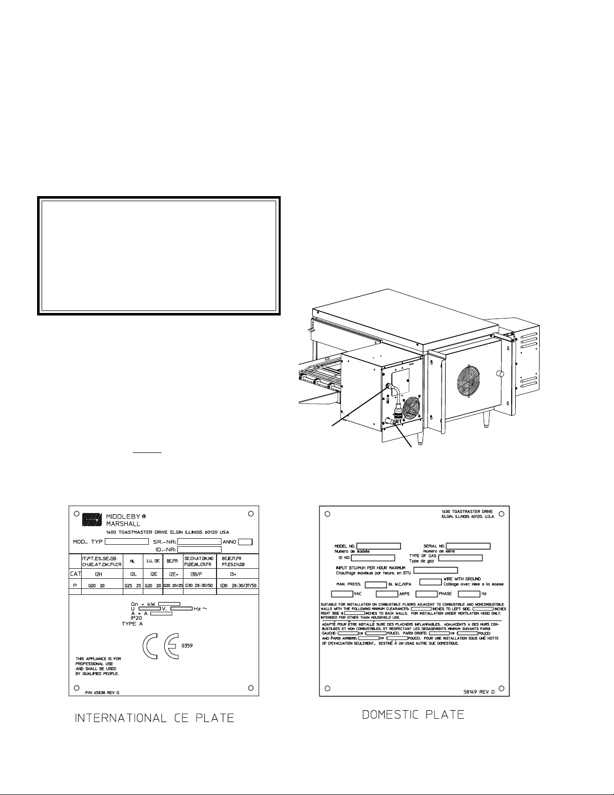
Check the oven data plate (Figure 2-10) before making any
electric supply connections. Electric supply connections
must agree with data on the oven data plate.
electrical code requirements. Copper is the recommended
material for the electrical supply conductors.
IV. ELECTRIC SUPPLY FOR GAS
HEATED OVENS
Power requirements for gas heated ovens are 208 240VAC, 1-phase, 3-wire (2 ‘hot’, 1 ground). Electrical
connection is made through a cord and plug. Using flexible
cable(s) for the electrical power supply conductors requires a 2″ (51mm) strain-relief fitting (not furnished) to
enable safe access to the terminal block from which oven
power is distributed.
The supply conductors must be of the size and
material (copper) recommended to provide the current required; (refer to the data plate for the ampere
specifications). The electric current rating for each
conductor supplying a PS520-Series Oven is 1.5A.
NOTE: The electric supply installation must satisfy the
requirements of the appropriate statutory authority, such
as the National Electrical Code (NEC), ANSI/NFPA70,
(U.S.A.); the Canadian Electrical Code, CSA C22.2; the
Australian Code AG601; or other applicable regulations.
A fused disconnect switch or a main circuit breaker
(customer furnished) MUST be installed in the electric
supply line for each oven; it is recommended that this
switch/ circuit breaker have lockout/tagout capability. The
electric supply connection must meet all national and local
ELECTRICAL
INLET
GAS INLET
Figure 2-11. Junction Connection Box
Figure 2-10. Typical Electric Oven Data Plate
14
Page 19
SECTION 2
INSTALLATION
V. GAS SUPPLY
CAUTION
DURING PRESSURE TESTING NOTE THE FOLLOWING:
1. The oven and its individual shutoff valve must be disconnected from the gas supply piping system during any
pressure testing of that system at test pressure in excess
of 1/2 psi (3.45 kPa).
2. The oven must be isolated from the gas supply piping
system by closing its individual manual shutoff valve
during any pressure testing of the gas supply piping
system at test pressure equal to or less than 1/2 psi (3.45
kPa).
3. If incoming pressure is over 14" W.C. (35mbar), a
separate regulator MUST be installed in the line BEFORE
the individual shutoff valve for the oven.
WARNING: To prevent damage to the control valve regulator during initial turn- on of gas, it is
open the manual shutoff valve very slowly.
After the initial gas turn-on, the manual shutoff valve must
remain open except during pressure testing as outlined
in the above steps or when necessary during service
maintenance.
A . Gas Utility Rough-In Recommendations
The following gas system specifications are STRONGLY
RECOMMENDED. Deviating from these recommendations
may affect the baking performance of the oven.
Gas Meter - 650 cfh (307
l/min) meter
Gas Line
• DEDICATED LINE from the gas meter to the oven
• 2" (50.8mm) pipe for natural gas
• 1-1/2" (38.1mm) pipe for propane
• Maximum length: 200' (61m). Each 90° elbow equals 7'
(2.13m) of pipe.
B . Gas Conversion
Where permitted by local and national codes, it is possible to
convert ovens from natural to propane gas, or from propane to
natural gas. Use the appropriate Middleby Gas Conversion Kit
for the specific oven model.
very important to
2. Connect a suitable pressure gauge to pipe line or to
outlet pressure tap of gas control concerned, to measure
burner pressure (measuring point must be as near to
burner as possible).
3. Make sure that the appliance is in operation and the
Moduplus® coil is energized with maximum current.
4. If maximum rate pressure needs adjustment, use an 8 mm
wrench to turn adjustment screw for maximum pressure
setting (clockwise to increase or counter-clockwise to decrease pressure), until the desired maximum outlet pressure is obtained.
5. Disconnect electrical connection of the Moduplus
®
.
6. Check minimum pressure setting and readjust if necessary. (See Adjusting Minimum Pressure Setting for proper
adjusting procedure.)
7. Reconnect pressure feedback connection (if appcable).
8. If minimum and maximum pressures are set, wire the
Moduplus
®
in circuit.
9. Close pressure tap screw.
E. Adjusting the Minimum Pressure Setting
1. Disconnect pressure feedback connection (if appcable).
2. Connect a suitable pressure gauge to pipe line or to outlet
pressure tap of gas control concerned, to measure burner
pressure (measuring point must be as near to burner as
possible).
3. Disconnect electrical connection of the Moduplus
®
.
4. Energize operator, set control in operation and wait until an
outlet pressure is recorded on pressure gauge.
5. If minimum rate pressure needs adjustment, use an 8 mm
wrench to turn adjustment screw for minimum pressure
setting (clockwise to increase or counter-clockwise to
decrease pressure), until the desired minimum outlet
pressure is obtained.
6. Check if main burner lights easily and reliable at minimum
pressure.
7. Reconnect pressure feedback connection (if appcable).
8. Close pressure tap screw.
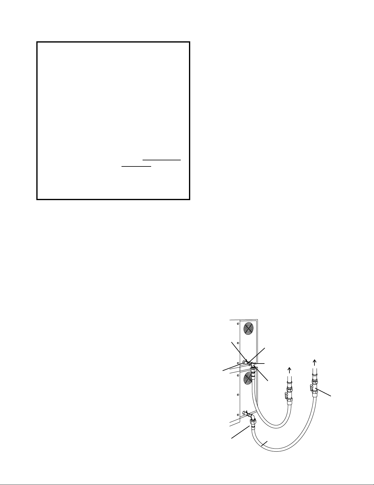
Figure 2-15 - Flexible Gas Hose Installation
CAUTION: The terms of the oven’s warranty require all start-
ups, conversions and service work to be performed by a Middleby Authorized Service Agent.
C . PS520 Propane Conversion
Two items have to be changed, to change the oven to LP:
1. Replace main orifices.
2. Adjust main gas regulator per instructions below.
Disconnect the manifold union closest to the main burner, and
remove the manifold assembly (four screws). Slide out the
manifold assembly (leaving the ignition and sense wires connected). Replace the main orifices.
Replace the main orifices on the manifold assemblies with the LP
units, and replace the manifold assembly. Reconnect the union.
D. Adjusting the Maximum Pressure Setting
1. Disconnect pressure feedback connection (if appcable).
1/2" gas line
tee with
pressure tap
15
1/2" gas
pipe nipple
Quick-
disconnect
device
3/4"-1/2"
gas pipe
reducer
3/4" gas
pipe nipple
90°
Elbow
Flexible
Gas Hose
To Gas
Supply
Pipe
Full-Flow
Gas
Shutoff
Valve
Individual gas
connection for
each oven
cavity
Page 20
SECTION 2
y
INSTALLATION
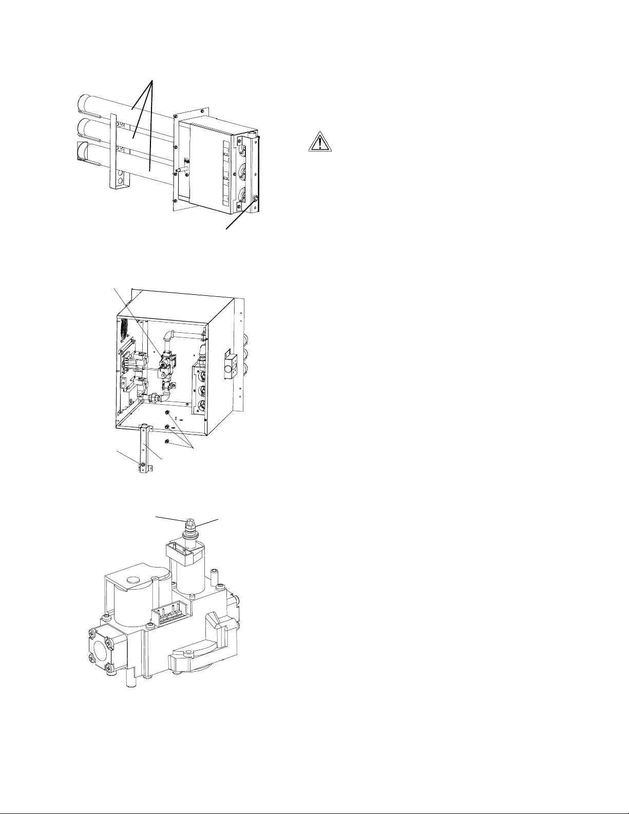
Figure 2-16. Gas Burner Assembly
Gas Burner
Manifold Pressure Tap
Figure 2-17. Burner Assembly
Gas
Valve
Main•
Pressure•
Ta p
Gas Burner
Assembl
Main•
Orifices
Figure 2-18. Gas Valve
Adjustment Screw (5 mm)
for minimum pressure
setting
Adjustment Screw
(8 mm) for maximum
pressure
setting
F. Checkout
After any adjustment, set appliance in operation and observe
through a component cycle to ensure that burner system components function correctly.
G. Maintenance
It is recommended to check yearly the minimum and the maximum setting and readjust them if necessary.
H. Connection
WARNING
Some procedures in this section may require
conversions, readjustments, or service on the oven's
gas system. Before performing these procedures, check
that the main gas supply valve and the circuit breaker/fused
=
disconnect are in the OFF ("O") position. After completing
these procedures, perform a gas leak test before operating
the oven.
CAUTION
The terms of the oven's warranty require all start-ups, conversions and service work to be performed by a Middleby Marshall
Authorized Service Agent. The installation, start-up and changes
required when changing from one gas type to another can be
performed ONLY by a certified professional.
NOTE: Certain safety code requirements exist for the installation
of gas ovens; refer to the beginning of Section 2 for a list of the
installation standards. In addition:
• In the USA, the installation must conform with local codes,
or in the absence of local codes, with the National Fuel Gas
Code, ANSI Z223.1.
• In Canada, the installation must conform with local codes,
or in the absence of local codes, with the Natural Gas
Installation Code, CAN/CGA-B 149.1, or the Propane
Installation Code, CAN/CGA-B 149.2, as applicable.
• In Australia, the installation must conform with AGA Codes
AG311 and AG601, and with any requirements of the
appropriate statutory authority.
• In CE countries, the gas supply connection should be
according to EN-203 (gas appliance directive) and to
applicable ISO 228-1 or ISO 7-1 recommendations. All
aspects of the gas supply connection must comply with
current IEC/CEE requirements and with all applicable
local, national, and international codes.
• For all ovens equipped with casters, the gas line connection
shall be made with:
- A connector that complies with the Standard for
Connectors for Movable Gas Appliances, ANSI Z21.69
(in USA), or Connectors for Movable Gas Appliances,
CAN/CGA-6.16 (in Canada).
Check the oven’s gas supply requirements to determine the
type of gas to be used with the oven. If the gas type required does
NOT match the local supply:
• For North American installations,
a conversion kit is
supplied with the oven to allow operation using propane
gas. Refer to Part B, Gas Conversion, in this section.
• For CE ovens, directions for converting the oven for use with
other gases are described in Part D.1,
Preparation for Use
with Various Gases, in this section.
16
Page 21

If the installation will use the supplied gas hose, be sure that
the 1/2" to 3/4" gas line fitting is attached. Refer to the
instructions in the gas hose package. One gas line connection
method is shown in Figure 2-15; however, compliance with
the applicable standards and regulations is mandatory.
Inlet and regulated gas pressures can be measured using
a “U” tube manometer at the tap locations shown in Figures
2-15 and 2-16.
1. Checking the Gas Supply (Inlet) Pressure
a. With the main gas supply valve closed and the circuit
breaker/fused disconnect in the OFF ("O") position, open
the inlet pressure tap shown in Figure 2-16 and attach a
manometer to the tap.
b. Depress the safety switches to allow the oven to operate.
c. Open the main gas supply valve. Switch the circuit
breaker/fused disconnect to the ON ("I") position.
d. Start the oven according the directions in the
section of this Manual. Adjust the temperature controller
to the maximum setting (316°C).
e. Measure the supply (inlet) pressure.
f. Switch the oven off. Close the main gas supply valve, and
switch the circuit breaker/fused disconnect to the OFF
("O") position. Remove the manometer, and close the
inlet tap.
g. Compare the measured supply (inlet) pressure to the
nominal pressures shown in Table 1-5 (in the Description
section of this Manual).
If the supply pressure is lower or higher than the nominal
pressure, the reason should be investigated and the gas
supplier contacted.
For natural gas ovens, if the measured supply pressure is
lower than 0.247psi, or higher than 0.363psi, contact the gas
supplier. DO NOT OPERATE THE OVEN or adjust the oven
controls.
Operation
SECTION 2
INSTALLATION
17
Page 22

SECTION 2
INSTALLATION
NOTES
18
Page 23
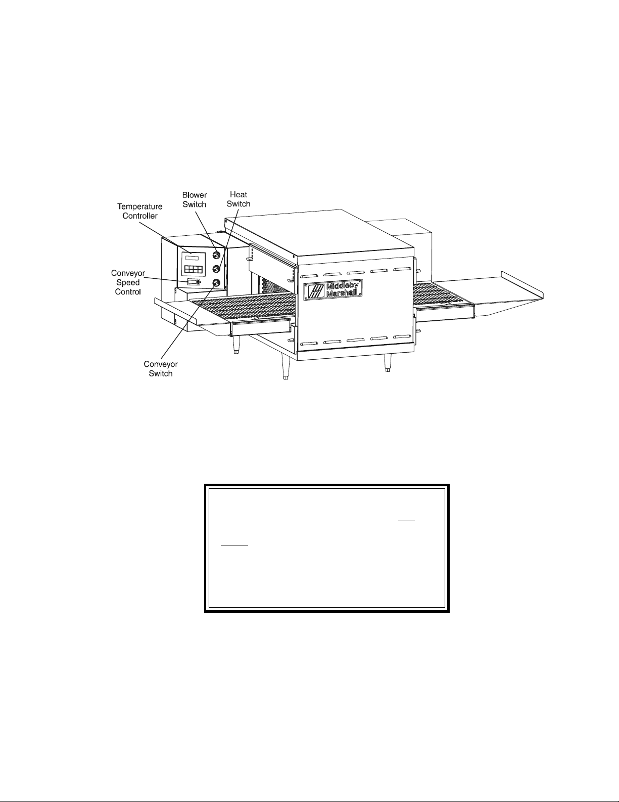
I. CONTROL FUNCTIONS
SECTION 3
OPERATION
SECTION 3
OPERATION
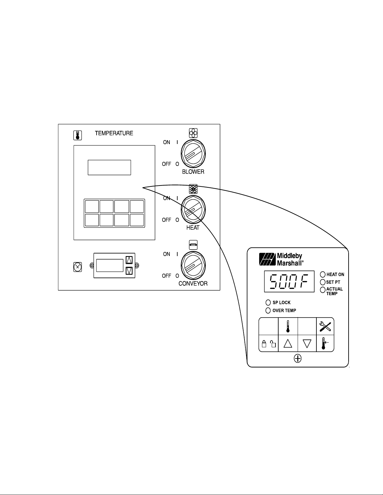
Figure 3-1. PS520-Series Oven Control Functions
WARNING
A possibility of injury from rotating parts and
electric shock exists in this oven.
Never disassemble or clean the oven with the
BLOWER switch or any other oven control turned
“ON” or “I”. Turn “OFF” or “O” and lockout or
tagout all electric power to the oven before
attempting to clean or service this oven.
19
Page 24
SECTION 3
OPERATION
II. COMPONENT INFORMATION AND
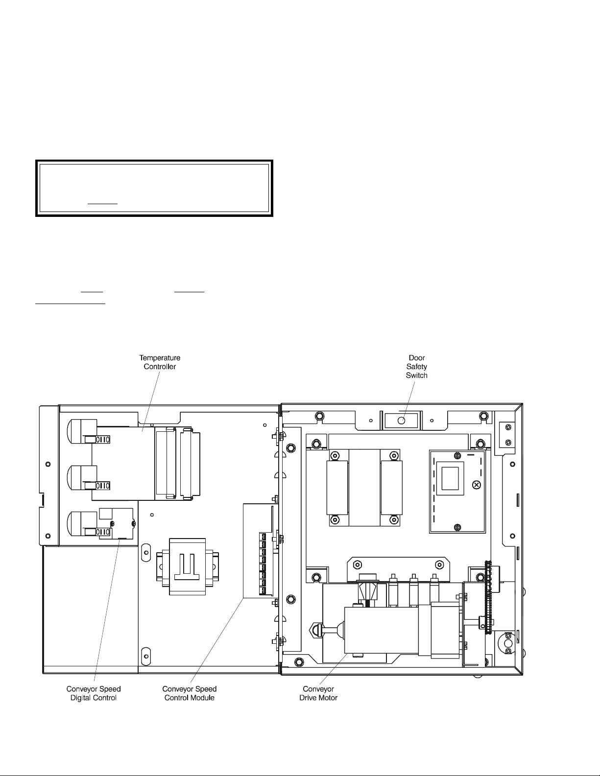
LOCATION (Figures 3-1 and 3-2)
A. Door Safety Switch
The Door Safety Switch is located at the lower right side
of control panel opening. Opening the control panel door
permits this switch to open, disconnecting power to all
electrical controls.
CAUTION
Do NOT touch the wires going to this safety switch.
Current is always present.
B. Blower Switch
The blower switch has two positions. The switch must
be “ON” or “I” for the main blowers to come on and permit
the oven to run. The fan circulates the air throughout the
oven and must stay on during baking and during the
cool down cycle above 200°F (93°C) to prevent blower
bearing damage. To protect the blower motor and
bearings a thermostatic override is built into the oven.
If the temperature inside the oven is over 180°F (82°C)
the main blower will continue to run after the blower
switch is turned to the “OFF” or “O” position.
C. Heat Switch
The “Heat Switch” allows the burner to activate. Activation
is determined by the settings on the Digital Temperature
Controller.
D. Temperature Controller
The temperature controller is a solid-state, PID type to
maintain the operator-set temperature. The temperature
controller continuously monitors the oven temperature and
turns on the modulating solid state relay controller. The
heat is on for the time required to maintain a constant oven
temperature.
The temperature controller contains a low-limit switch
which allows the oven to cool down to 200°F (93°C) before
shutting off the blower. A high-limit indication (ALM 1) will
appear on the display if the oven reaches 650°F (343°C).
Figure 3-2. Interior View of Control Console
20
Page 25
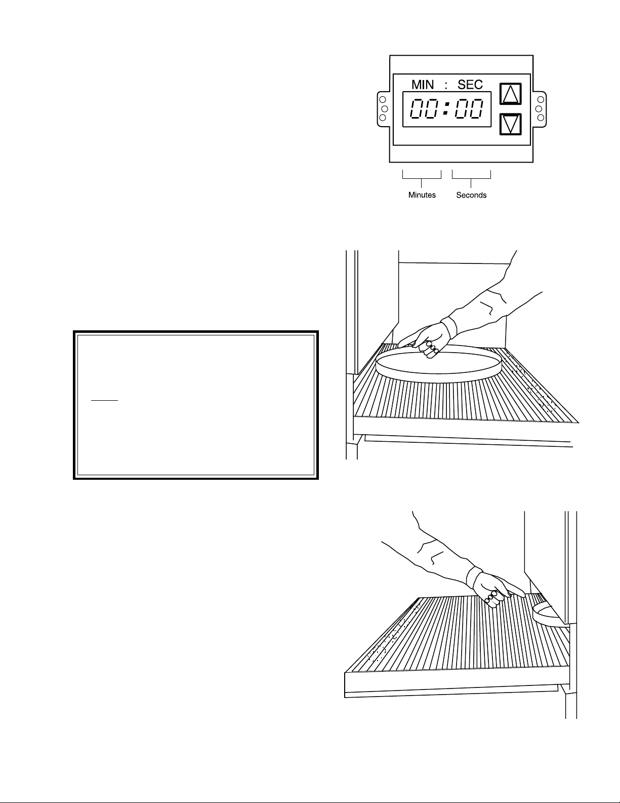
E. Conveyor
The on-off switch for the conveyor motor is on the control
panel. Also on the control panel is the digital conveyor
speed control. The digital control can be adjusted
from 1-10 min. bake time (conveyor speed).
Refer to Figure 3-3.
Conveyor speed is measured by the amount of time it
takes for an item to go through the bake chamber of the
oven.
MEASURING CONVEYOR SPEED.
SECTION 3
OPERATION
See Figures 3-4 and 3-5.
To check conveyor speed, place a product item at the
entrance end of baking chamber as shown. Time how long
it takes for the leading edge of the item to go from the
entrance end of the baking chamber to the exit end. This
should be the conveyor speed shown on the conveyor
speed digital control.
NOTE: In Figures 3-4 and 3-5, the oven shown is with the
conveyor running right to left.
WARNING
Possibility of injury from rotating parts and
electrical shock exist in this oven.
Never disassemble or clean the oven with the
blower switch or any other part of the oven
turned “ON” or “I”. Turn “OFF” or “O” and
lockout or tagout all electrical power to the
oven before attempting to clean or service
this oven.
Figure 3-3. Conveyor Speed Digital Control
Figure 3-4. Product at entrance end of baking
chamber – BEGINNING OF TIMING
21
Figure 3-5. Product at exit end of baking
chamber – END OF TIMING
Page 26
SECTION 3
OPERATION
WARNING
OVEN MUST BE KEPT CLEAR OF
COMBUSTIBLES AT ALL TIMES.
III. STEP-BY-STEP OPERATION
4. Set the temperature controller to the desired baking
temperature.
NOTE: For complete temperature controller operation
instructions refer to Step C.
5. Turn the HEAT switch (Figure 3-6) to the “ON” or “I”
position. Wait for the “Heat ON” light to turn on.
A. Startup Procedures
Daily Startup
1. Turn the BLOWER switch (Figure 3-6) to the “ON” or “I”
position. This starts the main blower fan and the cooling
fans. The blower circulates air through the air fingers and
must stay on during the cooking or baking process.
2. Check to see if the cooling fans (see Figure 1-8) are
operating when the blower switch (see Figure 3-6) is turned
“ON” or “I”. The cooling fans cool the control components
and blower motor. The cooling fans, located at the rear of
the oven blows air into and through the cabinet. Air is
exhausted through the front of the cabinet and also out the
front of the oven. Refer to Daily Maintenance Section for
fan intake checking procedure.
IMPORTANT NOTE
The cooling fan operates when the BLOWER
switch is turned “ON” or “I”. It must operate to keep
the control console below 140°F (60°C).
3. Turn the CONVEYOR switch (Figure 3-6) to the “ON” or
“I” position. This starts the conveyor belt moving through
the oven. Set the conveyor speed for the desired baking
time. Refer to the following Procedures E, F and G.
6. Oven will reach a baking temperature of 500°F (232°C)
in approximately 20 minutes. Allow the oven to cycle for
30 minutes after it has reached desired bake temperature.
The oven is now ready for baking.
Power Failure
In case of power failure, turn off all switches and remove
product. After power has been reestablished follow
normal startup procedure.
B. Shutdown Procedure
1. Turn the BLOWER and HEAT switches to “OFF” or “O”.
NOTE: The blowers will remain on until the oven temperature cools down to 200°F (93°C) at which time they will stop
automatically.
2. Make certain that there are no products left on the
conveyor inside the oven. Turn the CONVEYOR switch
to “OFF” or “O”.
22
Page 27
SECTION 3
OPERATION
Figure 3-6. Control Panel
23
Page 28
SECTION 3
OPERATION
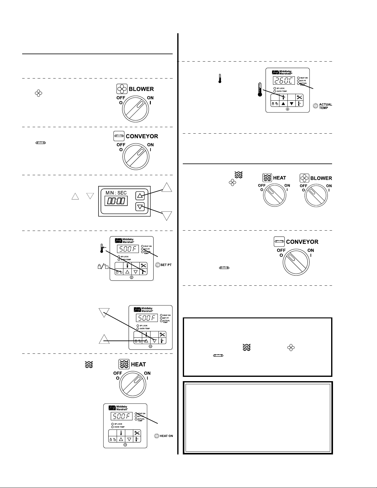
IV. NORMAL OPERATION - STEP-BY-STEP
A.Daily Startup Procedure
1. Check that the circuit breaker/fused disconnect is in the
on position.
2. Turn the "BLOWER"
( ) switch to the “ON”
("I") position.
3. Turn the "CONVEYOR"
( ) switch to the
“ON” ("I") position.
4. If necessary, adjust the
conveyor speed setting
by pressing the
pushbuttons on the conveyor speed controller to
change the displayed
bake time.
or
or
7. Wait for the oven to heat to the setpoint temperature.
Higher setpoint temperatures will require a longer wait.
The oven can reach a temperature of 500°F (232°C) in
approximately 15 minutes.
8. (Optional) Press the Temperature (
the Actual Temperature
in the display, and wait
for the "ACTUAL TEMP"
light to turn on. This allows you to monitor the
oven temperature as it
rises to the setpoint.
9. Allow the oven to preheat for 10 minutes after it has
reached the set point temperature.
B. DAILY SHUTDOWN PROCEDURE
1. Turn the "HEAT" (
"BLOWER" (
ches to the "OFF" ("O")
position. Note that the
blowers will remain in operation until the oven has
cooled to below 200°F
(93°C).
) key to show
) and
) swit-
wait
for
+
5. Adjust the temperature
controller to a desired set
temperature, if necessary.
• Press the Set Point
and Unlock keys at
the same time. Wait
for the "SET PT" light
to turn on.
• Press the Up Arrow
and Down Arrow
Keys as necessary
to adjust the setpoint.
6. Turn the "HEAT" ( )
switch to the "ON" ("I")
position, and wait for the
"HEAT ON" light to turn
on.
+
or
wait
for
wait
for
2. Make certain that there
are no products left on
the conveyor inside the
oven. Turn the "CONVEYOR" (
the "OFF" ("O") position.
3. After the oven has cooled and the blowers have turned
to the “OFF” or “O” position, switch the circuit breaker/fuse
disconnect to the “OFF” or “O” position.
) switch to
IMPORTANT
On gas ovens, if the "HEAT ON" light will not illuminate,
OR if the oven does not heat, the gas burner may not have
lit. Turn the "HEAT" (
VEYOR" (
for AT LEAST FIVE MINUTES before restarting the oven.
Then, repeat the Daily Startup procedure.
) switches to the "OFF" ("O") position. Wait
), "BLOWER" ( ), and "CON-
CAUTION
In case of power failure, turn all switches to the “OFF”
("O") position and remove the product. After the
power has been restored, perform the normal startup
procedure. IF THE OVEN WAS SWITCHED OFF FOR
LESS THAN 5 MINUTES,
MINUTES BEFORE RESTARTING THE OVEN.
WAIT FOR AT LEAST FIVE
24
Page 29
SECTION 3
OPERATION
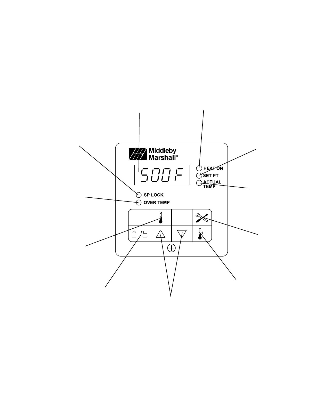
"SP LOCK"
Light
Lights when the
set point is locked
out from changes.
This setting can
only be changed by
service personnel.
OVERTEMP
Light
Lights when the oven
temperature is
greater than 650°F
(343°C). Refer to
Quick Reference:
Troubleshooting in
this section.
Display
Shows the Set Point
or the Actual Tem-
perature in degrees
Fahrenheit (F) or
Celsius (C).
"HEAT ON"
Light
Lights when the
burner is in
operation.
"SET PT"
(setpoint)
Light
Lights when the
set point is shown
in the display.
"ACTUAL TEMP"
Light
Lights when the Actual
Temperature is shown
in the display.
Temperature
Key
Press this key once
to view the Actual
Temperature in the
Display.
together with the Set
Point Key to allow the
changed. Changes
can only be made for
Unlock Key
Press this key
Set Point to be
60 seconds.
Up Arrow and Down
Arrow Keys
Press these keys to
adjust the Set Point up or
down. If the Set Point will
not change, refer to Set
Point Key and Unlock Key
in this section.
Service Key
Service use
only.
Set Point Key
Press this key
together with the
Unlock Key to allow
the Set Point to be
changed.
Changes can only be
made for 60 sec-
onds.
25
Page 30
SECTION 3
OPERATION
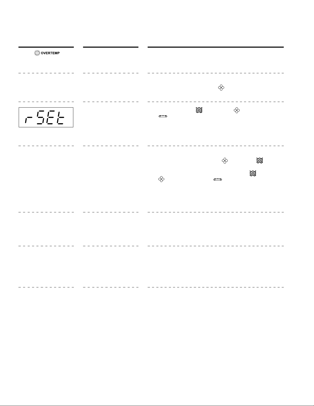
V. QUICK REFERENCE: TROUBLESHOOTING
SYMPTOM PROBLEM SOLUTION
light is lit, food product is
undercooked
Oven will not
turn on at all
appears in display,
oven is not heating
Oven will not heat
The oven temperature exceeded 650°F (343°C), and
the burner was automatically shut down.
Electrical power may not be
reaching the oven, or the
controls may be set incorrectly.
The oven did not reach
200°F (93°C) within 15 minutes of startup, and the oven
has stopped heating.
Controls may be set incorrectly.
• Follow the procedures under Daily Shutdown Procedures in
this section to shut down the oven. Contact your Middleby
Marshall Authorized Service Agent to determine and correct the
cause of the condition to prevent damage to the oven.
• Check that the circuit breaker/fused disconnect is turned on.
• Check that the "BLOWER"
position.
• Turn the "HEAT" (
( )switches to the "OFF" ("O") position.
• Wait for AT LEAST FIVE MINUTES before restarting the oven.
• Repeat the Daily Startup procedure.
• Check that the Set Point is correctly set.
• Check that both the "BLOWER"
are in the “ON” ("I") position.
• If the oven still will not heat,turn the "HEAT" ( ), "BLOWER"
( ), and "CONVEYOR" ( )switches to the "OFF" ("O")
position.
• Wait for AT LEAST FIVE MINUTES before restarting the oven.
• Repeat the Daily Startup procedure. Check that the Set Point
is above 200°F (93°C).
( ) Switch is in the “ON” ("I")
), "BLOWER" ( ), and "CONVEYOR"
( ) and "HEAT" ( ) Switches
Oven is operating, but
little or no air is blowing
from air fingers
Conveyor moves with a
jerky motion, or will not
move at all
Food products are
overcooked or
undercooked.
Air fingers may have been
reassembled incorrectly
after cleaning.
Conveyor may be jammed
on an object in the oven, or
conveyor belt or drive chain
tension may be incorrect.
Controls may be set incorrectly.
• Turn the oven to the “OFF” or “O” position, and allow it to cool.
Disconnect electrical power to the oven.
• Refer to Section 4,
bling the air fingers.
• Turn the oven to the “OFF” or “O” position, and allow it to cool.
Disconnect electrical power to the oven.
• Check if the conveyor is blocked by an object inside the oven.
• Refer to Section 4,
the conveyor and drive chain tension.
• Check that the set temperature and bake time settings are
correct.
Maintenance, for instructions on reassem-
Maintenance, for instructions on checking
IF THESE STEPS FAIL TO RESOLVE THE PROBLEM, CONTACT YOUR LOCAL MIDDLEBY MARSHALL
AUTHORIZED SERVICE AGENT. A SERVICE AGENCY DIRECTORY IS SUPPLIED WITH YOUR OVEN.
26
Page 31
SECTION 4
MAINTENANCE
SECTION 4
MAINTENANCE
WARNING
Before ANY cleaning or servicing of the oven, perform the following procedure:
1. Switch off the oven and allow it to cool. Do NOT service the oven while it is warm.
2. Turn the full-flow gas safety valve to the off position.
3. Turn off the electric supply circuit breaker(s) and disconnect the electric supply to the oven.
4. If it is necessary to move a gas oven for cleaning or servicing, disconnect the gas supply before moving the oven.
When all cleaning and servicing is complete:
1. If the oven was moved for servicing, return the oven to its
original location.
2. Reconnect the gas supply.
3. Reconnect the electrical supply.
WARNING
Possibility of injury from rotating parts and electrical
shock exist in this oven. Turn off and lockout or tagout
electrical supply to oven(s) before attempting to
disassemble, clean or service oven(s). Never disas-
semble or clean the oven with the blower switch or any
other part of the oven turned on.
WARNING
Before performing any maintenance work or cleaning,
turn main power switch off.
CAUTION
When cleaning do not use any abrasive cleaning
materials or water spray, wipe clean only. Never use a
water hose or pressurized steam cleaning equipment
when cleaning this oven.
4. Turn on the full-flow gas safety valve. Test the gas line
connections for leaks using approved leak test substances or thick soap suds.
5. Turn on the electric supply circuit breaker(s).
6. Perform the normal startup procedure.
NOTICE
If the oven is to be removed from its installed location
for servicing, perform the following procedure:
1. Switch off the oven and allow it to cool. Do NOT
service the oven while it is warm.
2. Turn off main circuit breakers and disconnect
connector from oven.
3. Move oven to desired location for servicing.
4. When servicing is complete, move oven to original
location.
5. Adjust legs to level oven.
6. Connect electrical connectors to oven.
7. Turn on main circuit breakers.
8. Follow normal startup instructions.
27
Page 32
SECTION 4
MAINTENANCE
I. MAINTENANCE - DAILY
A. Exterior
Everyday you should clean the outside of the oven with a
soft cloth and mild detergent.
WARNING
Never use a water hose or pressurized steam
cleaning equipment when cleaning the oven.
B. Cooling Fan
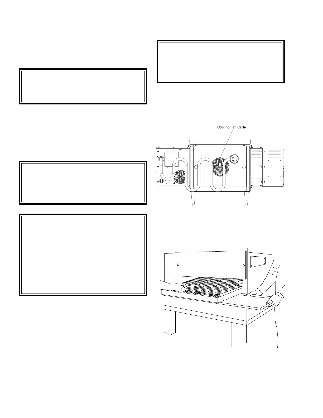
1. ONE COOLING FAN GRILLE AT THE REAR OF THE
OVEN MUST BE CLEANED DAILY - Clean grille with a
stiff nylon type brush.
2. Check the air intake of the cooling fan daily. The best
time to check is right after starting the oven.
IMPORTANT NOTE
The cooling fan operates when the blower switch
is turned to “ON” (“I”). It must operate to keep the
electrical control cabinet below 140°F (60°C).
D. Crumb Pans (Figure 4-2)
WARNING
Crumb pan is extremely hot while oven is
operating. Allow oven to cool before
removing crumb pan.
When the oven is cool remove and clean the crumb pan at
each end of the oven. Each crumb pan can be removed
by sliding it out, as shown in Figure 4-2. Reinstall the
crumb pans after cleaning.
WARNING
IF FAN BLADE IS NOT ROTATING, BROKEN,
OR FAN ASSEMBLY IS MISSING FROM MAIN
BLOWER MOTOR SHAFT, DO NOT OPERATE
OVEN. REPLACE COOLING FAN BLADE
BEFORE OPERATING OVEN. Serious damage
could be done to the burner blower motor and/or
solid-state electrical components if oven is
operated while cooling fan is not running or vent
grille is plugged.
3. Using a stiff nylon brush clean control compartment
vent grille.
C. Conveyor Belt (Figure 4-2)
Everyday, just after starting the oven, stand at the
unloading end of the conveyor, and with a brush, remove
food particles (crumbs, etc.) clinging to the conveyor belt,
brushing them into the crumb pan.
Figure 4-1. Oven Cooling Fans
Figure 4-2. Conveyor Belt and
Crumb Pan Cleaning
28
Page 33
SECTION 4
MAINTENANCE
II. MAINTENANCE - MONTHLY
NOTE: The oven interior may require cleaning more
than once a month depending on the volume of
baking. To clean the interior, you have to disassemble
some parts of the oven.
When cleaning your Series PS520 Oven note the
following:
PRECAUTIONS-
1. Do not use excessive water or saturation of oven
insulation will occur.
2. Do not use a caustic oven cleaner or the aluminized
finger manifold surfaces will be severely damaged.
When cleaning your oven, first remove all heavy debris
with a vacuum cleaner. Use a damp cloth for light cleaning.
For heavier cleaning of baked on grease and carbon
deposits use a non-caustic cleaner that will not react with
the aluminized finger manifold surfaces.
You can order non-caustic cleaner from your local authorized Middleby Marshall Parts Distributor in the quantities
listed:
Part # Quantity
27170-0244 Case of Quarts (6)
27170-0246 Case of Gallons (4)
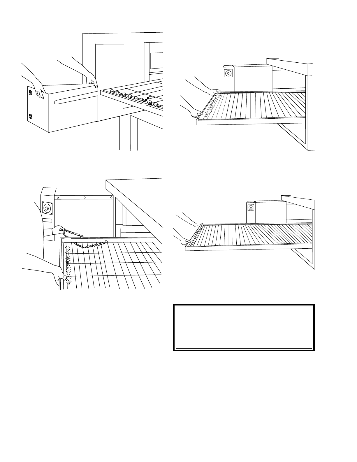
A. Removing Conveyor From Oven For Cleaning
1. Remove entry and exit trays.
2. Loosen (do not remove) two screws on housing guard.
3. Remove motor housing guard.
4. Lift conveyor and remove chain.
5. Lift other side of conveyor and push toward other side.
Figure 4-3.
29
Page 34
SECTION 4
MAINTENANCE
6. Remove conveyor as shown.
Figure 4-4.
Figure 4-5.
Figure 4-6.
Figure 4-7.
CAUTION
Be careful not to bump the drive sprocket while
handling the conveyor, to avoid damaging the
drive shaft.
30
Page 35
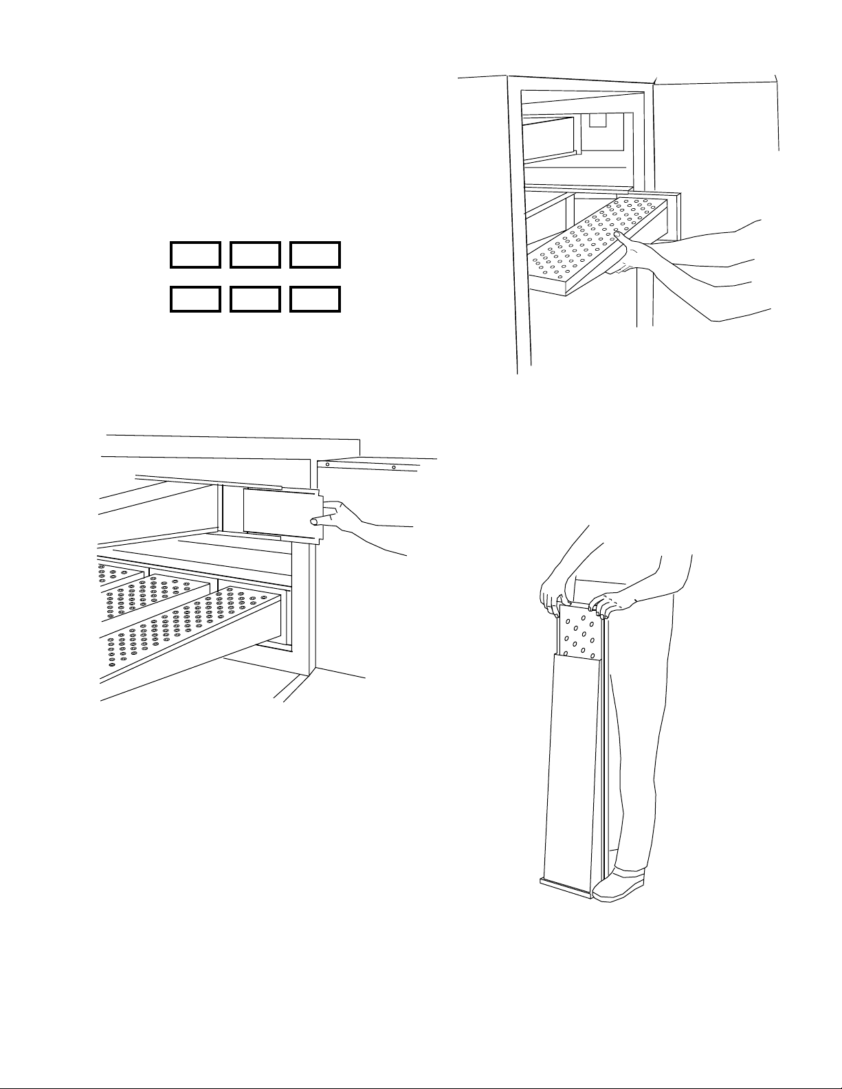
B. Air Fingers Disassembly For Cleaning
1. As the air fingers are removed use a felt pen to mark all
parts of the fingers. This includes the finger manifold, inner
plate and the outer plate (refer to Figure 1-9). If a blank or
choke plate is used, mark that plate also. Fingers are
marked in the order shown; as viewed from the front of the
oven. (The marks for an upper oven should be preceded
with a “U”, example UB1, UT2, etc.)
T1 T2 T3
B1 B2 B3
Standard Fingers
2. Slide blank plates straight out.
SECTION 4
MAINTENANCE
Figure 4-9.
4. With air fingers out, place them in an upright position to
remove the outer plate.
Figure 4-8.
3. Remove air fingers.
NOTE: Some oven users require a custom finger arrangement where the quantity of air fingers may vary.
You can remove top and bottom fingers and blank plates
from each or either end. It is highly recommended that
each finger be marked before removing so it is placed in
exactly the same position when reassembled
(refer to step 1).
5. Gently step on the lip of the finger and pull the outer
plate off.
Remove the air fingers, pull the finger at the back side - pull
straight out.
Figure 4-10.
31
Page 36
SECTION 4
MAINTENANCE
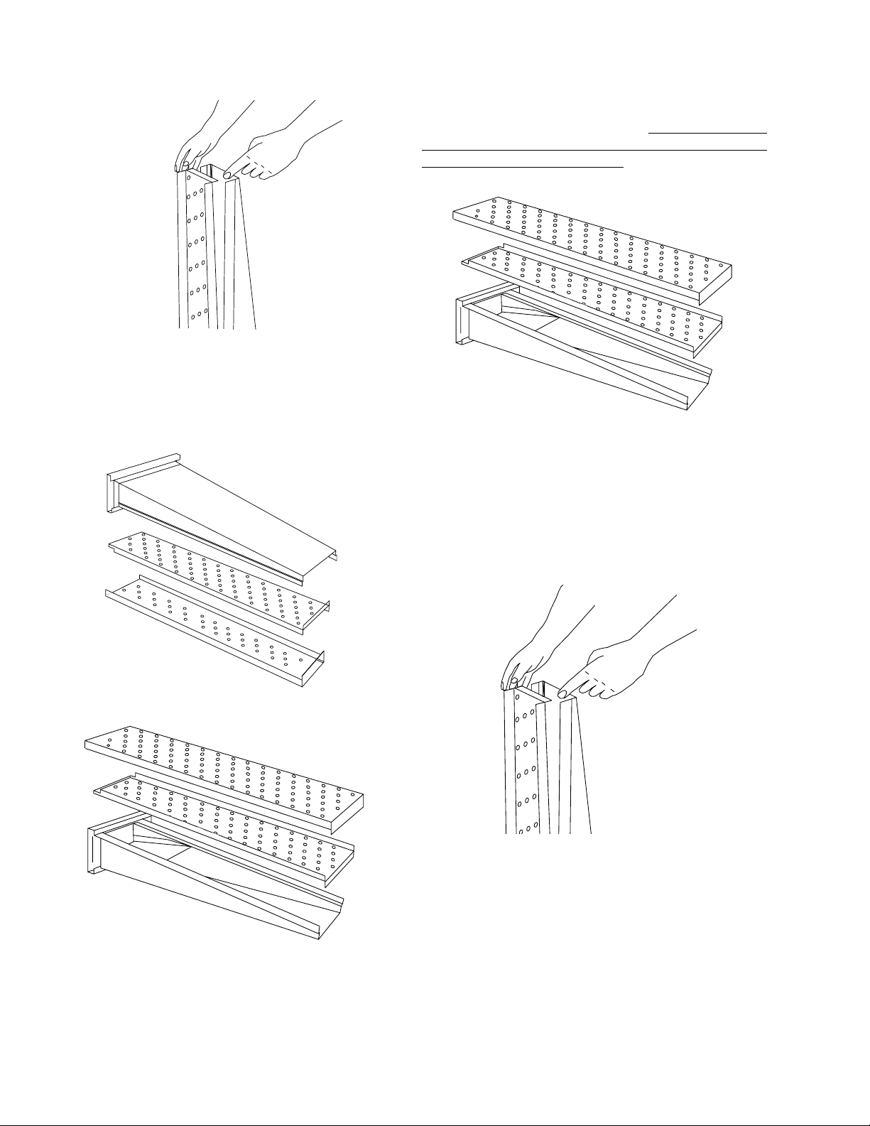
6. To remove the inner plate, pull the plate out and then up.
Figure 4-11.
7. The outer finger plate is stainless and may be cleaned
by either soaking in a hot, strong detergent solution or
using a caustic cleaner. The conveyor belt can also be
cleaned in the same way.
C. Reassembly of Air Fingers
1. Air fingers are made up of one inner plate, one outer
plate and the finger housing manifold. Be sure to match up
the markings (T1, T2, T3, etc.) on all the parts of the air
fingers as you are reassembling.
Figure 4-14.
2. Reassemble the inner plate. Keep your fingers clear so
you won’t pinch them. The inner plate of a finger will only
go in one way because of its design.
Figure 4-12. Standard Lower Finger
3. Replace the outer plate by placing your hands flat on
the top of the plate and pushing down. Keep your fingers
clear so you won’t pinch them.
Figure 4-15.
Figure 4-13. Standard Upper Finger
32
Page 37
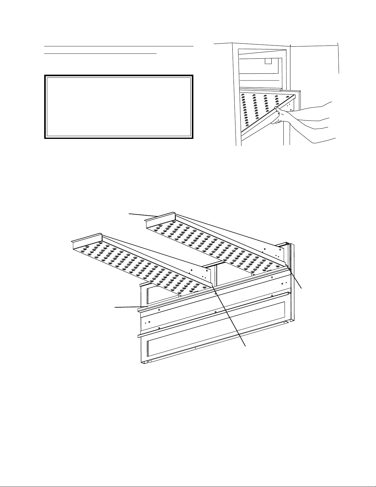
4. Replace the air fingers by pushing in at the back side.
Remember to replace them according to the numbers
marked on them when they were removed. They must go
back in the same way they came out.
IMPORTANT: When inserting fingers the tab on
the outer plate must be in the groove as shown in
Figure 4-18. There is a blocking tab on the outside
of the groove which will prevent inserting the
finger in the groove if the outer plate is moved
away from the flange of the finger manifold.
SECTION 4
MAINTENANCE
Figure 4-16.
Extended Lip
Flange of
Finger Manifold
Tab on
Outer Plate
Tab on
Outer Plate
Figure 4-17.
33
Page 38
SECTION 4
MAINTENANCE
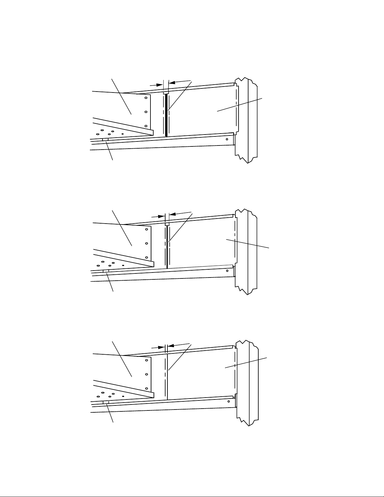
5. Install fingers and blank plates correctly with edges
interlocked and no space between edges.
Top Finger
Tab on Outer Plate of Finger
Located in Groove
Top Finger
Incorrect - Too
Much Space
Blank Plate
Incorrect - Too
Much Space
Blank Plate
Tab on Outer Plate of Finger
Located in Groove
Top Finger
Tab on Outer Plate of Finger
Located in Groove
Correct Edges Overlap
Completely
Blank Plate
Figure 4-18.
34
Page 39
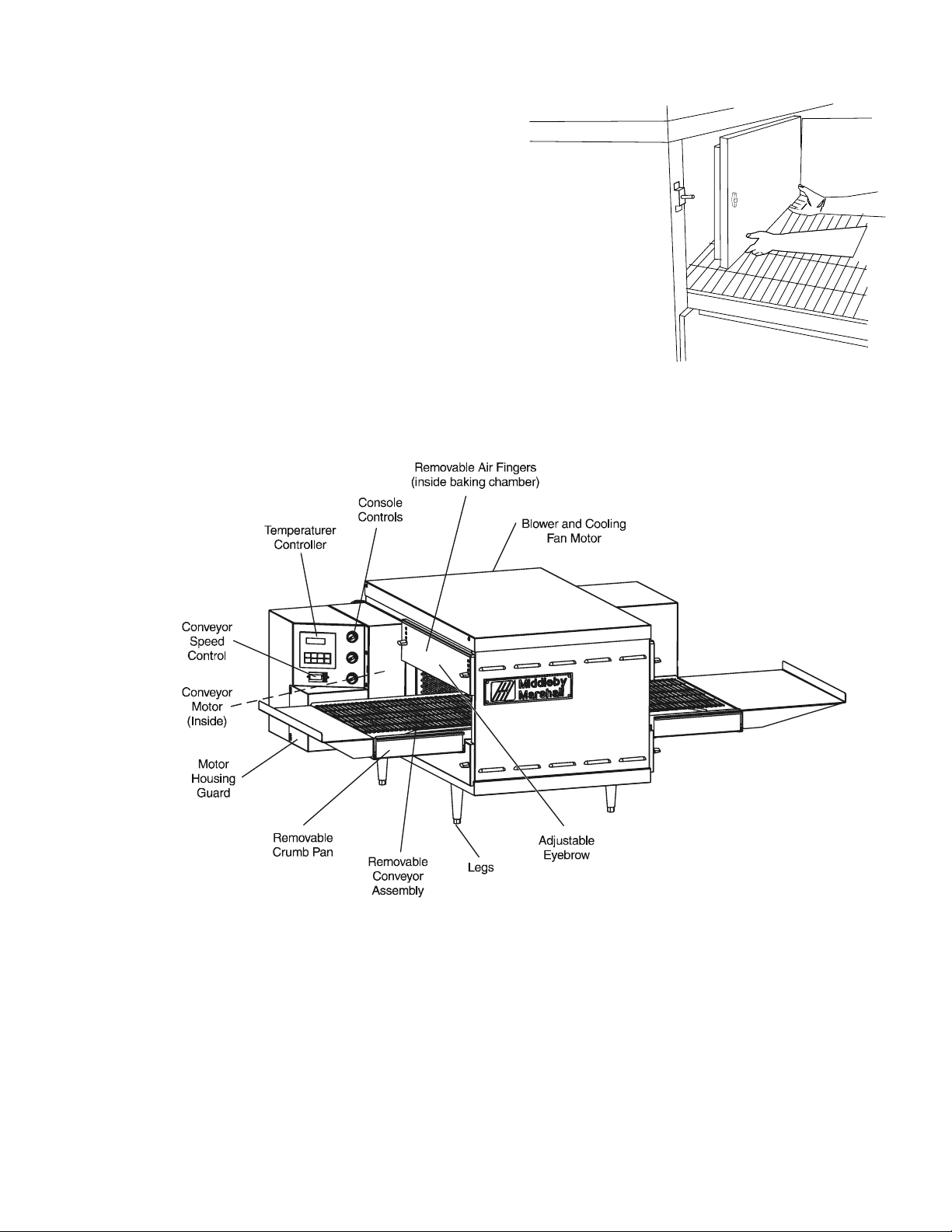
D. Reinstall End Plugs
1. Reinstall lower end plug. Be sure to tighten the wing
screw on the end plug.
2. Reinstall conveyor.
3. Reinstall upper end plug. Be sure to tighten two wing
screws on the end plug.
SECTION 4
MAINTENANCE
Figure 4-19.
Figure 4-20.
35
Page 40
SECTION 4
MAINTENANCE
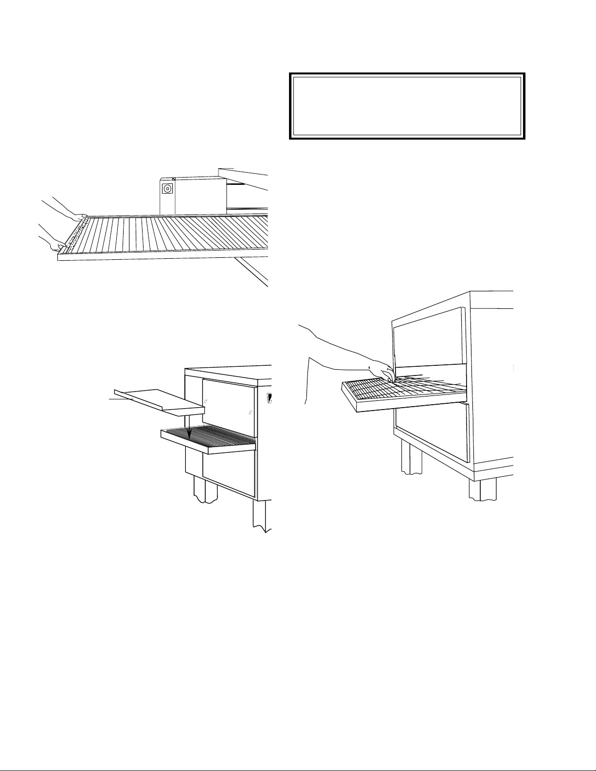
E. Conveyor Reassembly Into Oven
1. Lift conveyor and position it in oven as shown.
NOTE: Conveyor may be inserted into either end of oven.
If it is to be installed from the non-drive end of the oven the
drive sprocket assembly must be removed as shown in
conveyor disassembly section.
Figure 4-21.
2. Reinstall the conveyor extension.
F. Checking Conveyor Belt Tension
WARNING
Oven conveyor belt must be cool when adjusting
belt. Do not adjust belt if HOT.
1. With the conveyor assembly in the oven, stand at one
end of conveyor and check tension by lifting the conveyor
belt at the center of the oven chamber opening. The belt
should not lift higher that 1″ to 2″ (75mm to 102mm).
2. If conveyor belt is still not under proper tension, an
entire link must be removed. Use the following procedure
“H. Conveyor Belt Link Removal” to remove a link. If
conveyor belt is under proper tension proceed directly to
“J. Attaching Drive Chain”.
Conveyor Extension
Figure 4-23.
Figure 4-22.
36
Page 41
SECTION 4
MAINTENANCE
G. Conveyor Belt Link Removal
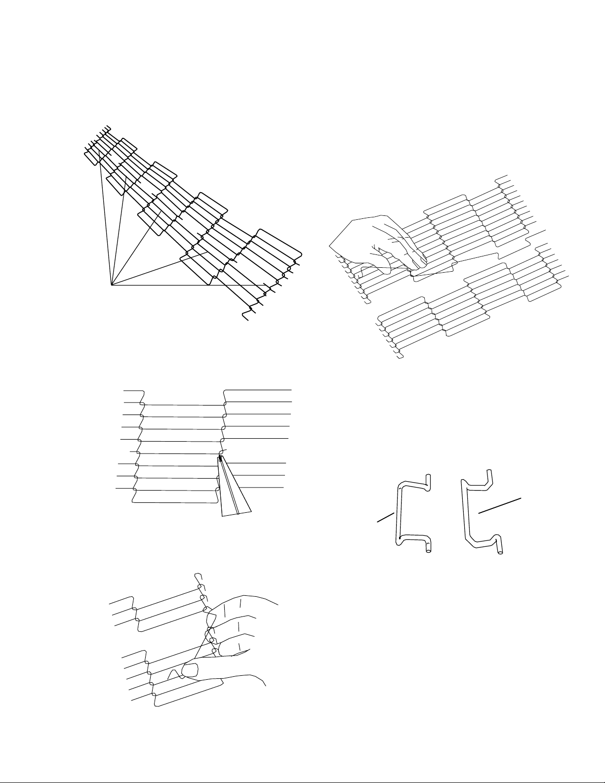
1. Using long nose pliers, an entire link can be removed
with the conveyor assembly either in or out of the oven.
Position master links at end of conveyor as shown in
Figure 4-24.
Master
Links
Figure 4-24.
4. Unhook the link to be removed.
5. Pull up on the belt link section and remove. Do not
discard the link removed as it may be used for making
spare master links.
NOTE: If a section of the conveyor belt is being replaced
it should be done now. Remove the links that need
replacing and use the section of conveyor belt furnished in
your installation kit to replace them.
2. Using long nose pliers, unhook master links at left end
of conveyor as shown in Figure 4-25.
Figure 4-25.
3. Remove the outside master links on the right and left
sides of the conveyor belt as shown in Figure 4-26.
Figure 4-27.
NOTE: Before connecting the inside master links, notice
that these links have a correct position (Figure 4-28). The
link at the right is in the correct (horns up) position for
inserting into the conveyor belt. The horns facing down are
in the incorrect position.
Correct
Position
Incorrect
Position
Figure 4-28.
Figure 4-26.
37
Page 42
SECTION 4
MAINTENANCE
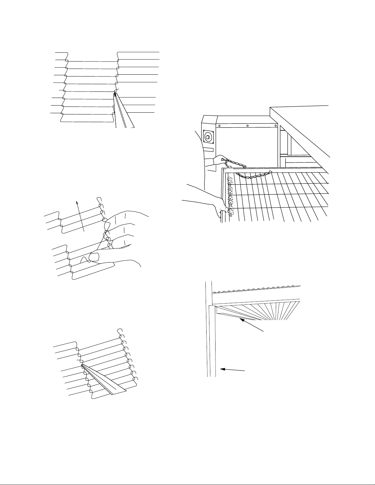
6. Reconnect the inside master links (Figure 4-29.)
Figure 4-29.
NOTE: The outside master links have right and left sides
to them. The right edge master link has an open hook
facing you as shown in Figure 4-30. This will match up with
the outer edges of the conveyor belt. Remember this hook
travels backwards on the conveyor.
Direction of travel
H. Attaching Drive Chain
1. If drive sprocket assembly was removed reassemble it
into the conveyor drive shaft. Be sure flat on end of drive
shaft aligns with set screw in conveyor shaft collar. Once
in place tighten 3/32″ set screw.
2. Lift conveyor and install drive chain to conveyor drive
sprocket and motor sprocket.
Figure 4-30.
7. Reconnect the outside master links.
8. Replace all parts removed from the oven.
Figure 4-32.
3. The angle plate located on the underside of the conveyor must be against the lower end plug. This is true on
both sides of oven.
Crumb Pan
Mounting
Bracket
Lower End Plug
Figure 4-33.
Figure 4-31.
38
Page 43
SECTION 4
MAINTENANCE
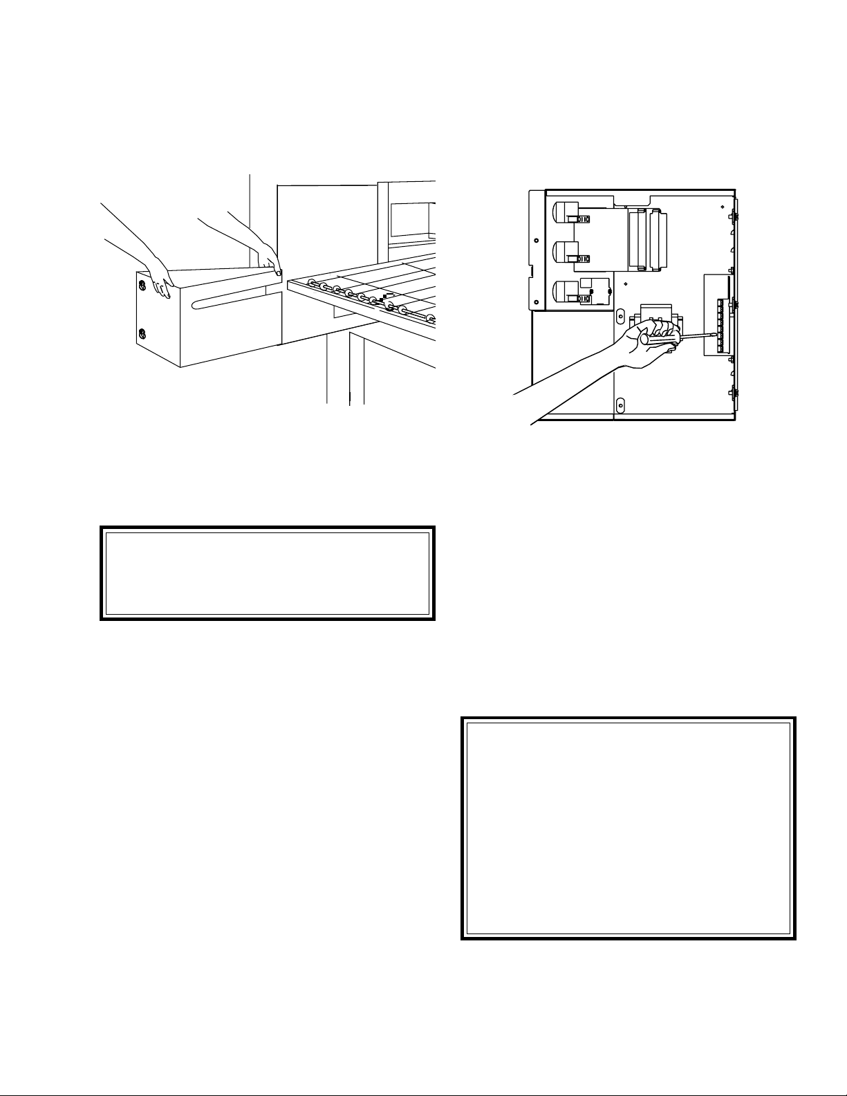
4. Reattach conveyor guard to control panel and secure
two screws.
Install both upper end plugs.
Figure 4-34.
III. MAINTENANCE - EVERY 3 MONTHS
A. Electrical Terminals
Open the control cabinet door by removing the three
screws from the control cabinet door. Tighten all electrical
control terminal screws including the electrical contactor
terminal screws as shown in Figure 4-35.
Figure 4-35.
B. Ventilation
Check that the air circulation throughout the oven is not
blocked and is working properly.
WARNING
Shut OFF all electrical power and lock/tag out the
switch before attempting maintenance work.
NOTE: It is recommended that the 3-month maintenance be performed by an authorized Middleby Marshall
technician.
IV. MAINTENANCE - EVERY 6 MONTHS
A. Check brushes on D.C. conveyor motor, when worn to
less than 1/10″ (2.4mm), replace the brushes.
B. Check your oven venting system.
C. Inspect and clean the burner nozzle and the spark
electrode assembly.
IMPORTANT NOTICES:
• Installation of replacement parts requiring access
to the interior of the oven is permitted only by an
authorized service technician.
• If there are any problems with the operation of the
oven, the authorized service technician must be
called.
• It is suggested to obtain a service contract with a
manufacturer’s authorized service technician.
39
Page 44
SECTION 4
MAINTENANCE
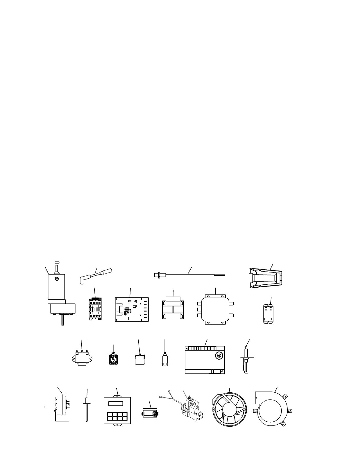
KEY SPARE PARTS KIT
An oven can be purchased with a Key Spare Parts Kit
(Figure 4-36). (The kit can be purchased when the oven is
ordered, or later, from a Middleby Marshall Authorized
Parts Distributor). The kit contains many of the crucial
PS520-SERIES GAS OVEN KEY SPARE PARTS KIT (Figure 4-36)
ITEM PART NO. ENGLISH DESCRIPTION QUANTITY
1 28041-0011 Contactor, DP 25A 208/240V 1
2 58390 Motor, Conveyor Drive w/Magnet 1
3 60671 Board, Amplifier Signal, 4-20VDC 1
4 32108 XFMR, 240V PRI 24V 65VA SEC 1
5 33812-5 Thermocouple, Type “J” Shielded 2.50 x 120 3
6 33813 Filter, RFI 1
7 38185 Assembly, Pickup Sensor 1
8 41872 Transformer, 240V (P), 24V (S) 25VA 1
9 44696 Switch, Rotary and Mounting Adapter 3
10 44697 Block, Contact 3
11 45644 Breaker, Circuit 240V 1A 1
12 48455 Ignitor, Single Rod PS536
13 50239 Ignition, Spark Module 24VAC 50/60 Hz 1
14 60598 Switch, Air .13″ WC 1
15 50794 Relay, 240VAC 2P1S 1
16 47321 Control, Combo 4-20MA, Burst 1
17 58323 Controller, Digital w/o Dip Switch 1
18 60679 Valve, Gas Modulating 1
19 36451 Fan, Cooling 230VAC 295 CFM 1
20 50240 Ignition Cable, 25″ 1
21 59002 Inshot Burner 2
22 52244 Main Blower 2
parts that can reduce serious downtime and loss of
production, if a failure occurs.
Replacement parts for this kit can be purchased from your
Middleby Marshall Authorized Parts Distributor.
1
220
14
1
89
5
3
10 11
16
17
7
13
5
12
19
4
18
21
15
22
Figure 4-36.
40
Page 45
SECTION 5
TROUBLESHOOTING
SECTION 5
TROUBLESHOOTING
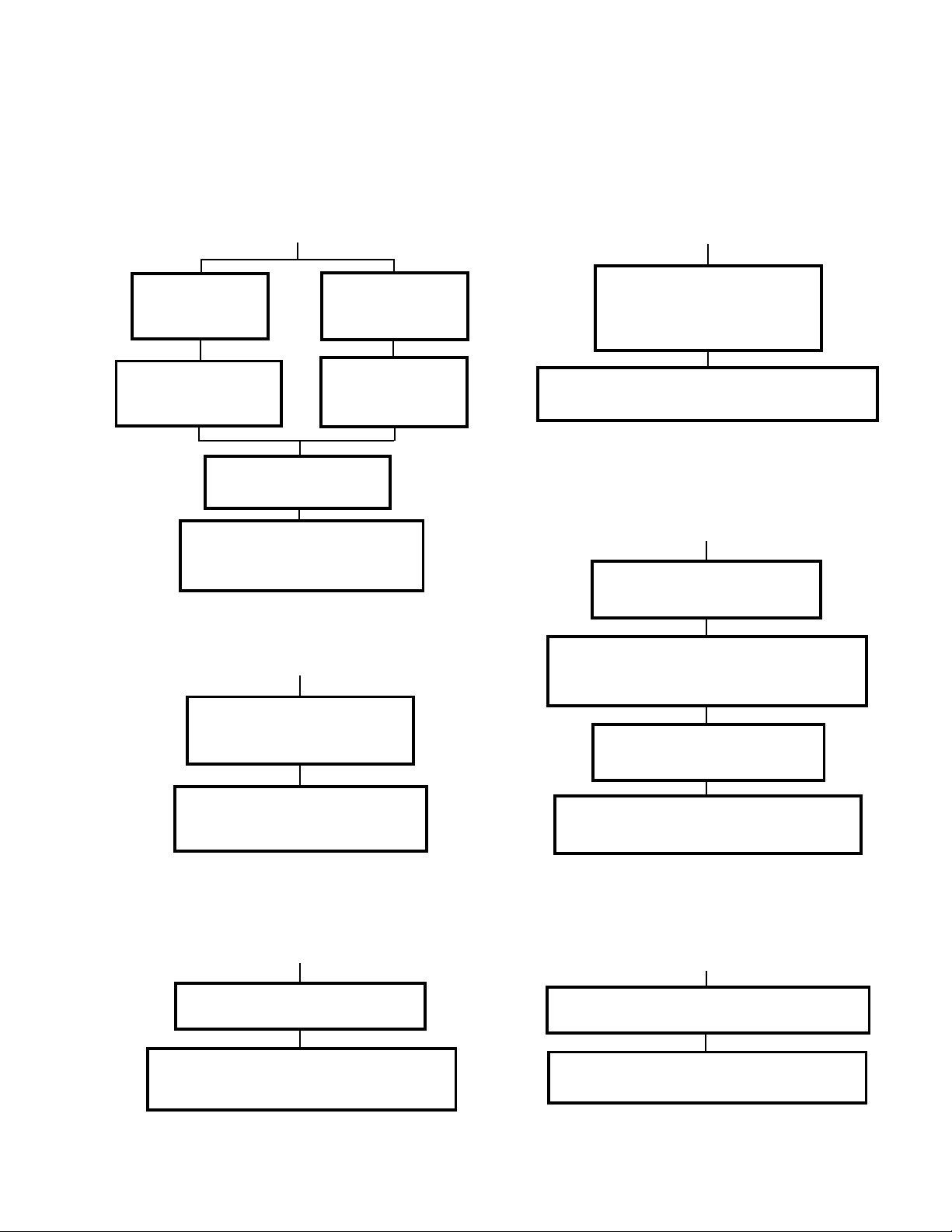
PROBLEM:
PRODUCTS ARE OVERCOOKED
OR UNDERCOOKED
Check for correct
setting of conveyor
speed control.
Set the conveyor speed
control at correct setting.
Verify the food
preparation process.
If products still cook incorrectly,
call your Middleby Marshall
Service Agency.
setting on tempera-
Check for correct
ture controller.
Turn temperature
control to correct
setting.
PROBLEM:
OVEN BLOWER AND CONVEYOR OPER-
ATE, YET THE OVEN IS NOT HEATING
Reset the temperature controller
to a new setting (above 200°F),
after turning the BLOWER switch
to off for 30 seconds.
Start the oven again. If the oven still does not
heat, call your Middleby Marshall Service Agency.
PROBLEM:
CONVEYOR WILL NOT HOLD PROPER
SPEED OR WILL NOT RUN AT ALL
Check whether the conveyor is
jammed on something in oven.
PROBLEM:
OVEN DOES NOT HEAT
Check to see if both BLOWER
switch and HEAT switch are in
the “ON” or “I” position.
If oven does not heat, call your
Middleby Marshall Service Agency.
PROBLEM:
BLOWER MOTOR IS RUNNING, YET LITTLE
OR NO AIR BLOWS FROM AIR FINGERS
Air fingers reassembled incorrectly,
after cleaning.
Assemble air fingers correctly, after cleaning.
Refer to Section 4 procedure, or call your
Middleby Marshall Service Agency.
Check for proper tension of conveyor drive
chain and conveyor belt. Refer to Section 4 for
correct procedure.
Check that the conveyor
drive sprocket is tight.
If conveyor still does not run correctly, contact
your Middleby Marshall Service Agency.
PROBLEM:
OVEN DOES NOT TURN ON WHEN ITS
SWITCHES ARE TURNED ON
Check that all electric supply switches are set to
the “ON” or “I” position. Then, start the oven.
If oven still will not start, contact your Middleby
Marshall Service Agency.
41
Page 46

SECTION 5
TROUBLESHOOTING
NOTES
42
Page 47
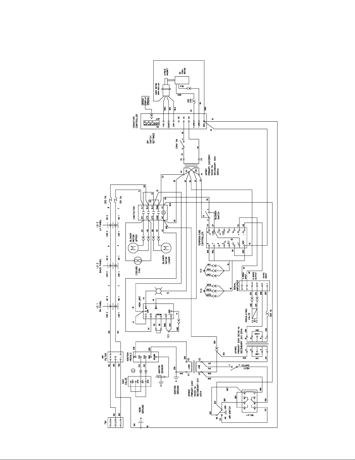
ELECTRICAL SCHEMATICS
SECTION 6
ELECTRICAL SCHEMATICS
SECTION 6
59113D
43
Wiring Diagram, G208-240 50/60 GO, PS520G
Page 48

WARNING
Improper installation, adjustment, alteration, service or maintenance
can cause property damage, injury or death. Read the installation,
operating and maintenance instructions thoroughly before
installing or servicing this equipment.
NOTICE
During the warranty period, ALL parts replacement and servicing should be performed by
your Middleby Marshall Authorized Service Agent. Service that is performed by parties
other than your Middleby Marshall Authorized Service Agent may void your warranty.
NOTICE
Using any parts other than genuine Middleby Marshall factory manufactured parts relieves
the manufacturer of all warranty and liability.
NOTICE
Middleby Marshall reserves the right to change specifications at any time.
Middleby is proud to support the Commercial Food Equipment
Service Association (CFESA). We recognize and applaud
CFESA's ongoing efforts to improve the quality of technical
service in the industry.
Middleby Cooking Systems Group • 1400 Toastmaster Drive • Elgin, IL 60120 • USA • (847)741-3300 • FAX (847)741-4406
www.middleby.com
 Loading...