

Page 1
©1998 Middleby Marshall Co., Inc.
Part No. 88210
-
0019
TTEECCHHNNIICCAALL
MAANNUUAALL
M
MODELS PS 310/360,
PS360
MODEL PS200
PACESETTER OVENS
PS200
Price $30.00
R. 5/98, Rev.B,Ver. 2
Page 2

WWAARRNNIINNGG
POST IN A PROMINENT LOCATION, INSTRUCTIONS TO BE
FOLLOWED IN THE EVENT YOU SMELL GAS.
Instructions to be followed in the event the user smells gas
shall be obtained by consulting the local gas supplier. If the
smell of gas is detected, immediately call the emergency
phone number of your local Gas Company. They will have
personnel and provisions available to correct the problem.
FFOORR YYOOUURR SSAAFFEETTYY
DO NOT STORE OR USE GASOLINE
OR OTHER FLAMMABLE VAPORS AND LIQUIDS
OVEN MUST BE KEPT FREE AND CLEAR
OF COMBUSTIBLES AT ALL TIMES
NNOOTTIICCEE
Using any parts other than genuine
Middleby Marshall factory
manufactured parts relieves the
manufacturer of all liability.
WWAARRNNIINNGG
There must be adequate clearance
construction. Clearance must also be
provided for servicing and operation.
NNOOTTIICCEE
between oven and combustible
NNOOTTIICCEE
Middleby Marshall (Manufacturer)
reserves the right to
change specifications
at any time.
WWAARRNNIINNGG
Do Not Obstruct The Flow Of Combustion
And Ventilation Air To And From Your Oven.
Page 3

Section
1 PS310/360 Functional Operation
1 I.
Gas Oven Sequence of Operation
1
A. Door Switch
1
B. Closing the Door Switch
1
C. Closing the Conveyor Switch
1
D. Closing the Blower Switch
1
E. Closing
the Heat Switch
1
F. Heat Switch Light
2 II.
Electric Oven Sequence of Operation
2
A. Door Switch
2
B. Closing the Power Relay
2
C. Closing Conveyor Switch
2
D. Closing Blower Switch
3
E. Closing the Heat Switch
3
PS200 F
unctional Operation
4 I.
Gas Oven Sequence of Operation
4
A. Door Switch
4
B. Closing the Door Switch
4
C. Closing the Convey or Switch
4
D. Closing the Blower Switch
4
E. Closing the Heat Switch
4
F. Heat Switch Light
5 II.
Electric Oven Sequence of Operation
5
A. Door Switch
5
B. Closing the Door Switch
5
C. Closing Conveyor Switch
5
D. Closing Blower Switch
6
E. Closing the Heat Switch
6
Section
2 – Servicing Components
7 I.
Digital Loop C
onveyor Control
7
A. Controller and Microcomputer Parts
8
B. Identifying Microcomputer Chip
9
C. Pre
-
troubleshooting Checkout Procedure For
Pacesetter Oven Digital Loop Conveyor Control
10
D. Controller/Motor Failure
12
E. Troubleshooting Convey or System
13
F. Troubleshooting Controller
15
G. Conveyor Control Check Using a
Frequency Counter
16
H. Conveyor Controller Pickup Test
17
I.
Conveyor Motor Test
18
J. Magnetic Pickup Replac
ement
19
PS360/570 Conveyor Sensor Wiring Changes
.
19A Dip Switch Conveyor Control Assembly
19B
II.
Temperature Controller
23
A. Honeywell (DialaPak) Controller
23
PS570S Thermocouple Wiring
26A B. Thermoc
ouple (Type J)
27
C. High Limit/Cooldown Switch
30
D. Troubleshooting Limit Switches
31
E. Testing Procedure for Temperature Controller
31
Part
1 - High Limit Switch and Thermocouple
Using the Altek Testing Device
31
Digital Temperature Controller P/N
28071
-
0028 31 B Part
2 - Oven Temperature Adjustment
32
Part 3
- Temperature Controller Main
Board Replacement
33 III. Motor Centrifugal Safety Switch
37 IV.
Air Pressure Sw
itch
PS200
ONLY
37 V. Gas Burner and Tram
38
A. Sequence of Operation
38
B. Intermittent Ignition Device
38
C. Gas Burner Components
39
Burner Pilot/lgnitor Assembly Changes,
7/22/91
42A Pilot Line Tee Kit
42C D.
Burner Troubleshooting
45
E. Burner Ignition System
- Start-up and Checkout
46
Honeywell Ignition Module
48A
VI.
High Flame Solenoid Valve
55 VII.
Main Gas Valve
55 VIII.
Low Flame Orifice
56
Gas Control Kit Changes,
11/27/91
56A
IX.
LP Conversion Kit
59
Gas Conversion Kit Changes,
12/19/94
60A
NOTE:
The PS
310
and
PS360 ovens are very
similar. For
simplification and
clarification purposes,
all references in this
manual to the
PS310 also include
the PS360 except
where noted.
TABLE OF CONTENTS
Page
Page 4

TABLE OF CONTENTS (continued) Page
X.
Pipe Sizing
61
XI.
Electrically Heated Oven
- PS310/360 ONLY
64
A. Ratings of Heating Elements
64
B. Operation
64
C. Checking the Heating Elements
65
D. Changing Heating Elements
67
XII.
Electric
ally Heated Oven
- PS200 ONLY
69
A. Rating of Heating Elements
69
B. Operation
69
C. Checking the Heating Elements
70
D. Changing Heating Elements
72
XIII.
Electrically Heated Oven
-
ALL MODELS
-
Mercury Contactor Replacement
74
A. Replacing the Coil And/Or Contact Tube
-
PS360 Electric Oven
75
B. Replacing the Coil And/Or Contact Tube
-
PS200
Electric Oven
76
XIV.
Blowers
- PS3
10/360
ONLY
80
A. Blower Balancing
80
B. Direction of Blow
er Rotation
- PS31
0/360
ONLY
81
XV.
Blowers
- PS200
ONLY
82
A. Blower Balancing
82
B. Blower Rotation
83
C. Main Blower Fan Shaft Bearings Lubrication
84
D. Checking Main Blower Fan Belt
84 E. PS200
Fan Shaft Bearing Replacement
and Alignment
85
PS200
Indirect Fan Drive Assembly Changes,
7/1/90
86A
XVI.
Air Distribution
88
A. Test Bake
88
B. Dough Test
88 XVII.
Finger Usage
&
Identification
90
A. Basic Finger Components Explanation
91
B. Chart o
f Fingers Used in Oven Models
93
C. Finger List with Photos and Explanations
94
D. Model
360
Standard (Shutter) Finger Adjustment
103 Section
3 - Troubleshooting
107
PS310/360
107
I. Blowers
107
II.
Conveyor
107
III. Heat (Gas Oven)
107
IV.
Trial for Flame
108
V. Heat (Electric Oven)
109 PS200
110
I. Blower Fan
110
II.
Conveyor
110
III. Heat (Gas Oven)
110
IV.
Trial for Flame
111
V. Heal (Electric Oven)
111
Section
4 113
Electrical Schematics
PS310/360
114 Gas Oven Schematic, 208
-
240V, 50/60Hz, 1Ph, 3W
114
Gas Oven Schematic, 208
-
240V, 50/60Hz,
1
Ph, 4W
114A
Gas Oven Scnematic, 208
-
240V,50/60Hz, 1Ph,2W, ExportOnly
115
Gas Oven Schematic, 190
-
380V, 50/60Hz,
1
Ph, 2W, Export Only
116
Electric Oven S
chematic, 200
-
220V, 50/60Hz, 3Ph, 3W, Export
117
Electric Oven Schematic, 208
-
240V, 50/60Hz, 3Ph, 4W
with Single Phase Blower Motor
118
Electric Oven Schematic, 208
-
240V, 50/60Hz, 3Ph, 4W
with 3 Phase Blower Motor
119
Electric O
ven Schematic, 240V, 50/60Hz, 3Ph, 3W
120
Electric Oven Schematic, 380V, 50/60Hz, 3Ph, 3W, Export Only
121
Electric Oven Schematie, 480V, 50/60Hz, 3Ph , 3W
122
Electric Oven Schematic, 400
-
440V, 50/60Hz, 3Ph, 3W, Export
123 PS
200
Schematics
124
Gas Oven
Schematic, 208
-
240V, 50/60Hz
, 1
Ph , 3W 124
Gas Oven Schematic,
208-240V, 50/60Hz,
1Ph,
4W 124A
Gas Oven Schematic, 200V, 50/60Hz, 1 Ph, 2W
125
Gas Oven Schematic, 208V, 50/60Hz, 1 Ph, 2W
126
Gas Oven Schematic, 220
-
240V, 50/60
Hz, 1Ph, 2W
127
Electric Oven
Schematic, 208
-
240V, 50/60Hz , 3Ph , 4W
128
Electric Oven
Schematic , 380V ,50/60Hz , 3Ph , 4W
129
Electric Oven Schematic , 400
-
416V, 50/60Hz ,3Ph, 4W
130
Appendix 131
Page 5

SECTION 1
PS31
0/360
FUNCTIONAL OPERATION
SECTION 1
FUNCTIONAL OPERATION
NOTE: This section to be used in conjunction with the electrical wiring diagrams in Section 4.
Complete description and troubleshooting of individual components are explained in Section 2.
D. Closing the Blower Switch
FUNCTIONAL OPERATION
I. GAS OVEN SEQUENCE OF OPERATION
AIl gas heated ovens operate on 208/230 V, single
phase.
Incoming power wiring for the (208/230 V) ovens
require 2-single phase 208/230 V supply (hot) lines, 1
neutral and 1 safety ground. From either hot line to
neutral the voltage should never exceed 130V.
A. Door Switch
Closing the control cabinet door will close the Door
Switch. The Door Switch has a "cheater" position.
When the control cabinet door is open, grasp the
switch actuator and pull it out as far as possible. This
will close the Door Safety Switch and permit
troubleshooting. Closing the control cabinet door will
reset the switch.
B. Closing the Door Switch
1. Closing the Door Switch permits a circuit to go
through the motor fuse, (two 9 Amp fuses per motor for
a 208/240 V oven).
Closing the Blower Switch energizes:
1. Two Cooling (axial fan) Motors.
2. Blower Motor Contactor (C1).
Closing this contactor starts both Blower Motors. When
both Blower Motors are up to speed a Centrifugal
Switch located inside the rear end of both Motors will
close, setting up the heat circuit.
3. Temperature Controller.
E. Closing the Heat Switch
Closing the Heat Switch completes a circuit:
1. Through the Heat Switch.
2. Through the Blower Motor Centrifugal Switches.
3. Through the Temperature High Limit Switch.
4. One circuit then goes to the:
a. Burner (L1).
b. Transformer (110 V to 24 V).
2. Also, closing the Door Switch permits a circuit to go
through a 9 amp fuse to one side of the Conveyor
Switch, Blower Motor Switch, Cooldown Relay and to
the Heat (Burner) Switch.
C. Closing the Conveyor Switch
Closing Conveyor Switch permits a circuit to go to the
Variable Speed Conveyor Motor Control. This serves
two functions:
1. One is to convert AC to DC.
2. The second is to achieve infinite speed control of the
Conveyor Motor by adjusting the Thumbwheel to the
desired conveyor belt speed.
c. Motor Relay Coil. On a cold start the heater on
this relay takes about 30 seconds to warm up before
the relay will energize. This gives an additional
prepurge.
d. Burner Blower Motor. As the Burner Motor
reaches full operating RPM the Centrifugal Switch
(Rear End Motor Switch) closes and applies voltage to
the Burner Control. This energizes the Ignitor Control
Spark Transformer and the Pilot Valve. The spark then
lights the Pilot. The Flame Sensor proves the presence
of the pilot flame and the Ignitor Control then shuts off
the spark. At the same time, the Main Burner Valve is
opened. The Main Burner is then ignited.
1
Page 6

SECTION 1
II.
ELECTRIC OVEN SEQUENCE OF OPERATION.
FUNCTIONAL OPERATION
If the Pilot does not light within approximately 90
seconds, the oven will shut down. All 310/314/360's
have 100% lockout modules for oven shut down.
The Pilot and Main Gas Valve will stay on (open) as
long as the Heat Switch is ON and the flame is
proven. If the flame goes out for any reason the Pilot
will try to light for 90 seconds, and then go into
automatic lockout. To relight the Pilot after it has gone
into automatic lockout the Burner must be turned OFF
for 60 seconds and then turned ON again.
e. Temperature Controller (Terminal 5) Power for
the Primary relay contacts for the high flame valve.
As long as the temperature inside the oven is below
the setting of the Temperature Controller the
Thermocouple will energize the Temperature
Controller.
When the Temperature Controller is energized, one
set of the contacts of the controller energize the High
Flame Solenoid, another set of contacts close and
energize the green primary output light located in the
upper left -hand corner of the Temperature Controller
dial.
F. Heat Switch Light
The Heat Switch light is an extremely useful
troubleshooting tool. If after turning the Blower Switch
and Heat Switch ON the Heat Switch does not light
this indicates a problem with one of the safety
switches (Blower Centrifugal Switch).
If the Heat Switch does light it indicates a problem in
the Burner Unit (Relay, burner blower motor, control
board) or High Limit Switch.
When the oven reaches the desired setting of the
Temperature Controller, the Temperature Controller
will be de-energized. This will de-energize the High
Flame Valve and the green primary output light. The
Burner will remain ON in the low flame mode. When
the temperature drops a few degrees the
Temperature Controller will energize and re-energize
the High Flame Solenoid.
During cooldown the Temperature Controller dial will
continue to read oven temperature.
NOTE: The red light on the Temperature Controller will
stay ON at fire-up each day until the oven temperature
goes above 180° F(82°C).
NOTE: This section to be used in conjunction with the
electrical wiring diagrams, in Section 4. Complete
description and troubleshooting of individual
components are explained in Section 2.
All electrically heated ovens operate on a
208/230/380/440V, 3 phase, 4 wire system. The fourth
wire is for a 120 V neutral ground. This 120 V neutral
ground eliminates the need for a control transformer.
Where a neutral is not available a 240/110V transformer
is supplied.
A. Door Switch
1. Closing the control cabinet door will close the Door
Switch. The Door Switch has a "cheater" position. When
the control cabinet door is open, grasp the switch
actuator and pull it out as far as it will go. This will close
the Door Safety Switch and permit troubleshooting.
Closing the control cabinet door will reset the switch.
NOTE: On all electrically heated ovens high voltage is
present at fuses and contactors in machinery
compartment.
B. Closing the Door Switch
Closing the Door Switch permits a circuit to go to one
side of the Conveyor Switch, Blower Motor Switch and
to the Heat Switch (208/240 V ovens use one 5 amp
fuse in this circuit).
C. Closing Conveyor Switch
The Temperature Controller also incorporates both
the High Limit Safety and the cooldown features The
High Limit relay will shut the oven burner OFF if the
oven goes above 650° F. If this occurs the red light
located in the upper right corner of the Temperature
Controller will be lit.
When the Heat and Blower Switches are turned OFF
the Cooldown Relay will allow the blowers to remain
ON until the oven temperature falls to 180° F (82°C).
Closing Conveyor Switch permits a circuit to go to the
Variable Speed Conveyor Motor control. This serves
two functions:
1. One is to convert AC to DC.
2. The second is to achieve infinite speed control of the
Conveyor Motor by adjusting the thumbwheel to the
desired belt speed.
2
Page 7

D. Closing Blower Switch
Closing Blower Switch energizes:
1. Two Cooling (axial fan) motors.
2. Blower Motor Contactors (C4 and C5).
Closing this contactor starts both blower motors. When
both Blower Motors are up to speed a Centrifugal
Switch located inside the rear end of both Motors will
close setting up the heating circuit.
E. Closing the Heat Switch
Closing the Heat Switch completes a circuit:
1. Through the Heat Switch.
2. Through the Blower Motor Centrifugal Switch.
3. Through the Temperature Override Switch.
4. To the primary relay contacts of the Temperature
Controller.
When the Thermocouple located inside the oven
indicates that the temperature inside the oven has
fallen below the set point indicated on the Temperature
Controller the Relay Switch inside the Temperature
Controller will energize Contactors C1, C2 and C3.
This will in turn energize the three banks of 8 KW
heaters.
SECTION 1
FUNCTIONAL OPERATION
5. When the Temperature Controller is calling for
heat, another set of contacts from the Temperature
Controller close and energize the green primary
output light located in the upper left -hand comer of the
Temperature Controller dial face.
The High Limit Safety and the Cooldown features are
located separately from the temperature controller.
The High Limit Relay will shut the heat circuit OFF if
the oven goes above 650° F (343°C). If this occurs
the red light located in the upper right comer of the
Temperature Controller will be lit.
When the Heat and Blower Switches are turned OFF
the Cooldown Relay will allow the blowers to remain
ON until the oven temperature falls to 180° F (82°C).
During cooldown the Temperature Controller dial will
continue to read oven temperature.
6. When the oven reaches the desired setting of the
Temperature Controller, the Temperature Controller
will be de-energized. This will de-energize the coils
C1, C2 and C3. This will also de-energize the green
primary output light. When the temperature drops a
few degrees the Temperature Controller will energize
again, re-energizing contactors C1, C2 and C3.
3
Page 8

SECTION 1
PS200
the relay will energize
. This gives an additional
d. Burner Blower Motor. As the Burner Motor
FUNCTIONAL OPERATION
D. Closing the Blower Switch
FUNCTIONAL OPERATION
I. GAS OVEN SEQUENCE OF OPERATION
All gas heated ovens operate on 208/230 V, single
phase.
Incoming power wiring for the (208/230 V) ovens
require 2-single phase 208/230 V supply (hot) lines, 1
neutral and 1 safety ground. From either hot line to
neutral the voltage should never exceed 130V.
A. Door Switch
Closing the control cabinet door will close the Door
Switch. The Door Switch has a "cheater" position.
When the control cabinet door is open, grasp the switch
actuator and pull it out as far as possible. This will close
the Door Safety Switch and permit troubleshooting.
Closing the control cabinet door will reset the switch.
B. Closing the Door Switch
1. Closing the Door Switch permits a circuit through a 9
amp fuse to one side of the Blower Motor Switch,
Cooldown Relay and to the Heat (Burner) Switch.
C. Closing the Conveyor Switch
Closing Conveyor Switch completes a circuit to go to
the Variable Speed Conveyor Motor Control. This
serves two functions:
1. Supplies power to one side of the Conveyor Switch.
2. Energizes Blower Motor Contactor (C1).
Energizing this contactor starts the Blower Motor.
When the Blower Motor is up to speed an air pressure
switch located in the control compartment senses the
air pressure in the air plenum and closes a switch.
This completes the heat circuit.
3. Energizes the Temperature Controller.
E. Closing the Heat Switch
Closing the Heat Switch completes a circuit:
1. Through the Heat Switch.
2. Through the Air Pressure Switch.
3. Through the Temperature High Limit Switch.
4. One circuit then goes to the:
a. Burner (L1).
b. Transformer (110 V to 24 V).
c. Motor Relay Coil. On a cold start the heater on
this relay takes about 15 seconds to warm up before
prepurge.
1. One is to convert AC to DC.
2. The second is to achieve infinite speed control of the
Conveyor Motor by adjusting the Thumbwheel to the
desired conveyor belt speed.
reaches full operating RPM the Centrifugal Switch
(Rear End Motor Switch) closes and applies voltage to
the Burner Control. This energizes the Ignitor Control
Spark Tr ansformer and the Pilot Valve. The spark then
lights the Pilot. The Flame Sensor proves the.
presence of the pilot flame and the Ignitor Control then
shuts off the spark. At the same time, the Main Burner
Valve is opened. The Main Burner is then ignited.
4
Page 9

If the Pilot does not light within approximately 90
seconds, the oven will shut down. All PS200's have
100% lockout modules for oven shut down.
The Pilot and Main Gas Valve will stay on (open) as long
as the Heat Switch is ON and the flame is proven. If the
flame goes out for any reason the Pilot will try to light for
90 seconds, and then go into automatic lockout. To
relight the Pilot after it has gone into automatic lockout
the Burner must be turned OFF for 60 seconds and
then turned ON again.
e. Temperature Controller (Terminal 5) Power for
the Primary relay contacts for the high flame valve.
As long as the temperature inside the oven is below
the setting of the Temperature Controller the
Thermocouple will energize the Temperature
Controller.
When the Temperature Controller is energized, one
set of the contacts of the controller energize the High
Flame Solenoid, another set of contacts close and
energize the green primary output light located in the
upper left -hand comer of the Temperature Controller
dial.
F. Heat Switch Light
The Heat Switch light is an extremely useful
troubleshooting tool. If after turning the Blower Switch
and Heat Switch ON the Heat Switch does not light this
indicates a problem with the Air Pressure Switch.
If the Heat Switch does light it indicates a problem in
the Burner Unit (Relay, burner blower motor, control
board).
When the oven reaches the desired setting of the
Temperature Controller, the Temperature Controller
will be de-energized. This will de-energize the High
Flame Valve and the green primary output light. The
Burner will remain ON in the low flame mode. When the
temperature drops a few degrees the Temperature
Controller will energize and re-energize the High Flame
Solenoid.
The Temperature Controller also incorporates both the
High Limit Safety and the cooldown features The High
Limit relay will shut the oven burner OFF if the oven
goes above 650° F. If this occurs the red light located in
the upper right comer of the Temperature Controller
will be lit.
When the Heat and Blower Switches are turned OFF
the Cooldown Relay will allow the blowers to remain ON
SECTION 1 FUNCTIONAL
OPERATION
until the oven temperature falls to 180° F (82°C).
During cooldown the Temperature Controller dial will
continue to read oven temperature.
NOTE: The red light on the Temperature Controller
will stay ON at fire-up each day until the oven
temperature goes above 180° F (82°C).
II. ELECTRIC OVEN SEQUENCE OF
OPERATION.
NOTE: This section to be used in conjunction with
the electrical wiring diagrams, in Section 4.
Complete description and troubleshooting of
individual components are explained in Section 2.
All electrically heated ovens operate on a 208/230 V,
3 phase, 4 wire system. The fourth wire is for a 120 V
neutral ground. This 120 V neutral ground eliminates
the need for a control transformer.
A. Door Switch
1. Closing the control cabinet door will close the Door
Switch. The Door Switch has a "cheater" position.
When the control cabinet door is open, grasp the
switch actuator and pull it out as far as it will go. This will
close the Door Safety Switch and permit trouble
shooting. Closing the control cabinet door will reset
the switch.
NOTE: On all electrically heated ovens high voltage
is present at fuses and contactors in machinery
compartment.
B. Closing the Door Switch
Closing the Door Switch permits a circuit to go to one
side of the Conveyor Switch, Blower Motor Switch and
to the Heat Switch (208/240 V ovens use one 9 amp
fuse in this circuit).
C. Closing Conveyor Sw itch
Closing Conveyor Switch permits a circuit to go to the
Variable Speed Conveyor Motor control.
This serves two functions:
1. One is to convert AC to DC.
2. The second is to achieve infinite speed control of
the Conveyor Motor by adjusting the thumbwheel to
the desired belt speed.
5
Page 10

Controller will be lit.
read oven temperature.
SECTION 1
FUNCTIONAL OPERATION
D. Closing Blower Switch
Closing Blower Switch energizes:
1. Supplies power to one side of Conveyor Switch.
2. Blower Motor Contactor.
Closing this contactor starts the blower motor. When the
Blower Motor is up to speed an Air Pressure Switch
located inside the control compartment senses the air
pressure in the air plenum and closes contacts. This
completes the heat circuit.
E. Closing the Heat Switch
Closing the Heat Switch completes a circuit:
1. Through the Heat Switch.
2. Through the Air Pressure Switch.
3. Through the Temperature High Limit Switch.
4. To the primary relay contacts of the Temperature
Controller.
5. When the Temperature Controller is calling for heat,
another set of contacts from the Temperature Controller
close and energize the green primary output light located
in the upper left -hand comer of the Temperature
Controller dial face.
The High Limit Safety and the Cooldown features are
located separately from the Temperature Controller. The
High Limit Relay will shut the heat circuit OFF if the oven
goes above 650° F (343°C). If this occurs the red light
located in the upper right comer of the Temperature
When the Heat and Blower Switches are turned OFF the
Cooldown Relay will allow the blowers to remain ON until
the oven temperature falls to 180° F (82°C). During
cooldown the Temperature Controller dial will continue to
6. When the oven reaches the desired setting of the
Temperature Controller, the Temperature Controller will
be de-energized. This will de-energize the coils C1, C2
and C3. This will also de-energize the green primary
output light. When the temperature drops a few degrees
the Temperature Controller will energize again, reenergizing contactors C1, C2 and C3.
When the Thermocouple located inside the oven
indicates that the temperature inside the oven has fallen
below the set point indicated on the Temperature
Controller the Relay Switch inside the Temperature
Controller will energize Contactors C1, C2 and C3. This
will in turn energize the three banks of 8 KW heaters.
6
Page 11

SECTION 2 SERVICING
I. DIGITAL LOOP CONVEYOR CONTROL
SECTION 2
SERVICING COMPONENTS
COMPONENTS
The Digital Loop Conveyor Control is used to set and
monitor the speed of the conveyor. Included in the control
is a Microcomputer connected to a thumbwheel switch
and a Magnetic Pickup Wheel on the motor shaft. As the
magnetic wheel attached to the motor shaft turns, the
revolutions of the magnet are monitored by the Hall
Device. The Hall Device is located next to, but not
touching, the magnetic wheel. The signals are sent to the
Microcomputer and the computer compares the motor
speed with the speed set by the thumbwheel. The
Microcomputer increases or decreases the voltage to the
gearmotor depending on the signal.
Power Must Be Off Before Replacing The
Microcomputer And A Middleby Marshall
Qualified Service Technician Must Be Present.
NOTE: To property service this equipment you must
use a good quality Digital Meter, preferably with a
frequency counter feature. An Analog Meter will not
NOTE: The basic controller is the same for all
Pacesetter Ovens (Models 314, 310, 360, 200). The
only parts that must be changed per the oven model
is the Microcomputer on the board. This is an
advantage for the service representative because
only one basic controller, one pickup and two styles of
motors and Microcomputers must be stocked. See
Figure 1 for description of parts.
WARNING
CAUTION
The Microcomputer Must Be Removed With The
Proper Equipment Such As A Microcomputer
Removal Tool (MMPN 27170-0190).
Page 12
SECTION 2
Terminal
SERVICING COMPONENTS
C. Pre -troubleshooting Checkout Procedure For Pacesetter Oven Digital Loop Conveyor
Control
1. Before troubleshooting the digital loop conveyor control check the following:
a. Conveyor belt tight.
b. Drive chain tight and aligned.
c. Drive sprockets tight (set screws).
d. Axial fan running and clean (cooling).
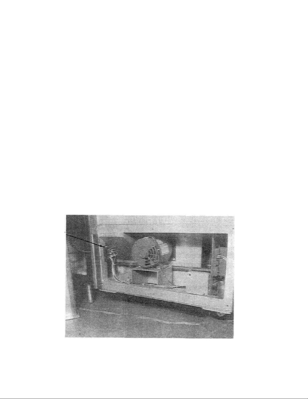
e. Motor and pickup wires on Conveyor Terminal Block are secure (see Figure 2), also wires on controller
are secure.
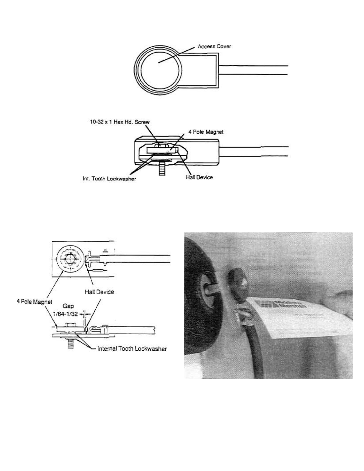
2. Check the Pickup for the following (see Figures 3 & 4):
a. Pickup is secure.
b. Magnet is not cracked or chipped.
c. Magnet is not rubbing on plastic housing.
d. Mounting bolt is not worn or bent.
e. Pickup bearing in good condition.
f. On old style pickup (see Figure 4) gap between magnet and Hall Device is spaced approximately 1/16"
or a business card thickness.
Block
Figure 2. Terminal Block in Motor Compartment on PS360.
10
Page 13
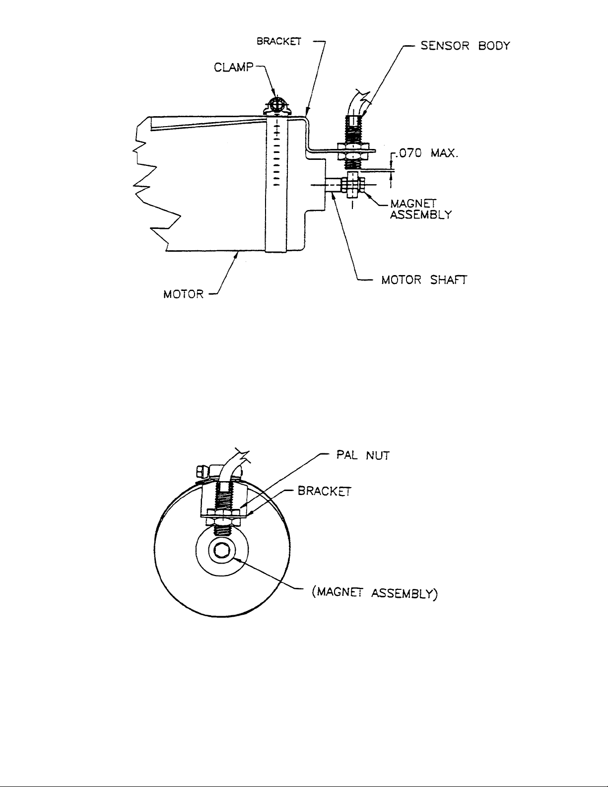
FIGURE 1
10A
Page 14
SECTION 2
SERVICING COMPONENTS
NOTE: Maximum Ambient Temperature 160° F.
Figure 3. Pickup
NOTE: 1. Maximum Ambient Temperature 160° F
Figure 4. Old Style Pickup
Originally Used on PS350 and Early 360 Ovens
11
Page 15
SECTION 2
SERVICING COMPONENTS
D. Controller/Motor Failure
When the conveyor controller fails, it is very possible
that a snorted conveyor motor caused the problem.
Unless the motor is changed, the installation of
another conveyor controller will simply result in
burning up the new controller.
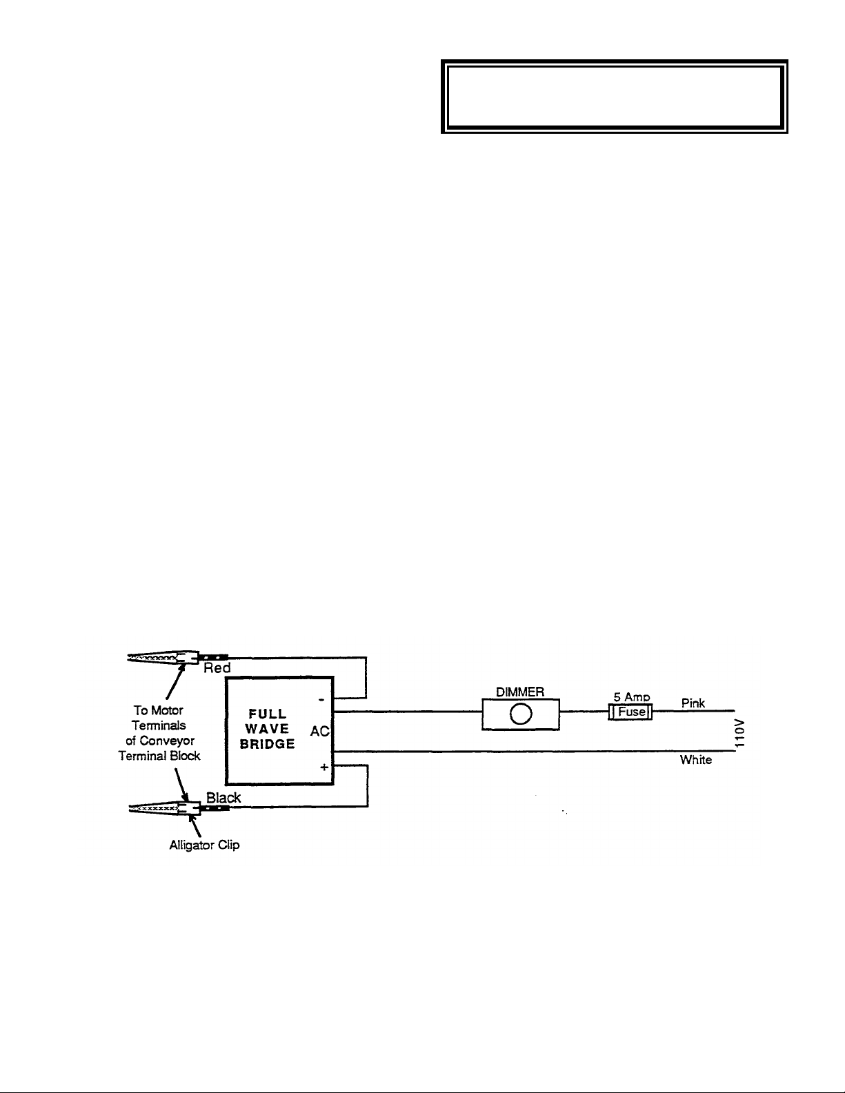
You are strongly advised to bypass the conveyor
controller and install the tester unit (see Figure 5) in
any oven that has burned up the conveyor controller
before installing a new conveyor controller to be sure
the problem is in the controller and not the motor. It is
much less expensive to bum out the tester than
another conveyor controller.
The components for this tester can be purchased at
any Radio Shack store or any good electronic supply
house. This tester is not nearly as accurate or
sensitive as the conveyor controller. If it is left on the
oven it will give inconsistent baking results. Therefore,
CAUTION!
DO NOT turn conveyor switch on while Field
On a PS310/360 remove the Red and Black motor
lead wires from the terminal block (Figure 2) and
attach motor leads to field tester.
On a PS200 disconnect the Red and Black motor
lead wires from the speed controller and then attach
motor leads to field tester.
NOTE: To reverse conveyor motor direction,
interchange Red and Black DC leads. The dimmer
switch must be turned over half way to start the
motor. It then can be turned down to the desired
motor speed.
Components Needed:
1 - Full wave AC-DC Bridge, 400 volt, 4 ampere
(Radio Shack P/N 276-11743).
1 - Light Dimmer Switch (5 amp rating).
1 - In line 5 amp AC fuse enclosed in plastic case.
2 - Alligator clips.
Figure 5. Field Tester For Conveyor Drive
Motor Controllers
12
Page 16
Ye
All wiring between Controller, Magnetic
Check for 120 Vac
Repair wire
Comple
te the pickup/Controller Test
Replace
Replace
Conveyor still
Complete the Motor Test
Replace
Conveyor still
Replace Speed
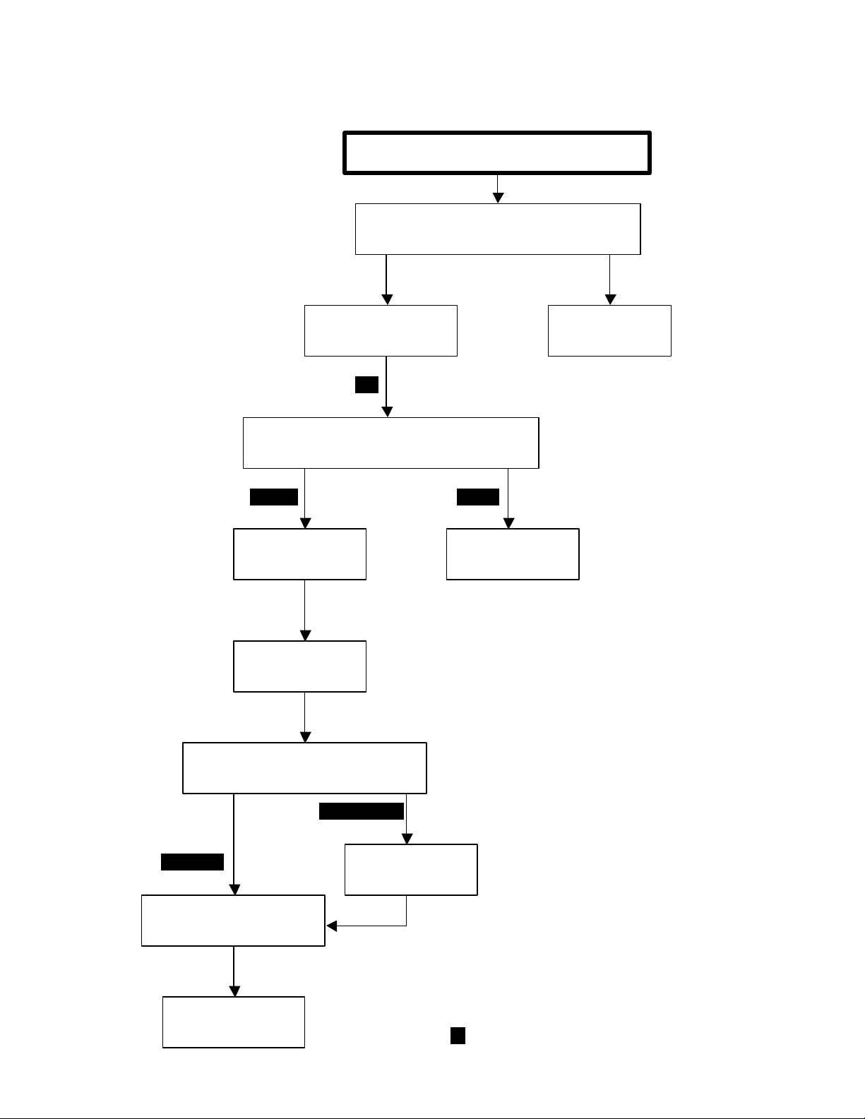
E. Troubleshooting Conveyor System
SECTION 2
SERVICING COMPONENTS
MOTOR ALWAYS RUNS FULL SPEED
Pickup and Motor in good condition
s
to Speed Controller
Yes
(See Pages 16 & 17)
Passed Failed
Microprocessor
runs to fast
Magnetic Pickup
No
connection
Motor OK
runs too fast
Control Board
as explained on Page 18
Motor Failed
Motor
13
Page 17
Yes
No
SECTION 2
Is thumbwheel speed selector
Set speed to customer
All wiring between Motor and Speed
Check for 120 Vac
Is there DC volta
ge present
Trace wiring
and
Replace
Still no DC
Complete the Motor Test
Replace
Motor still
Repair wire
Motor still
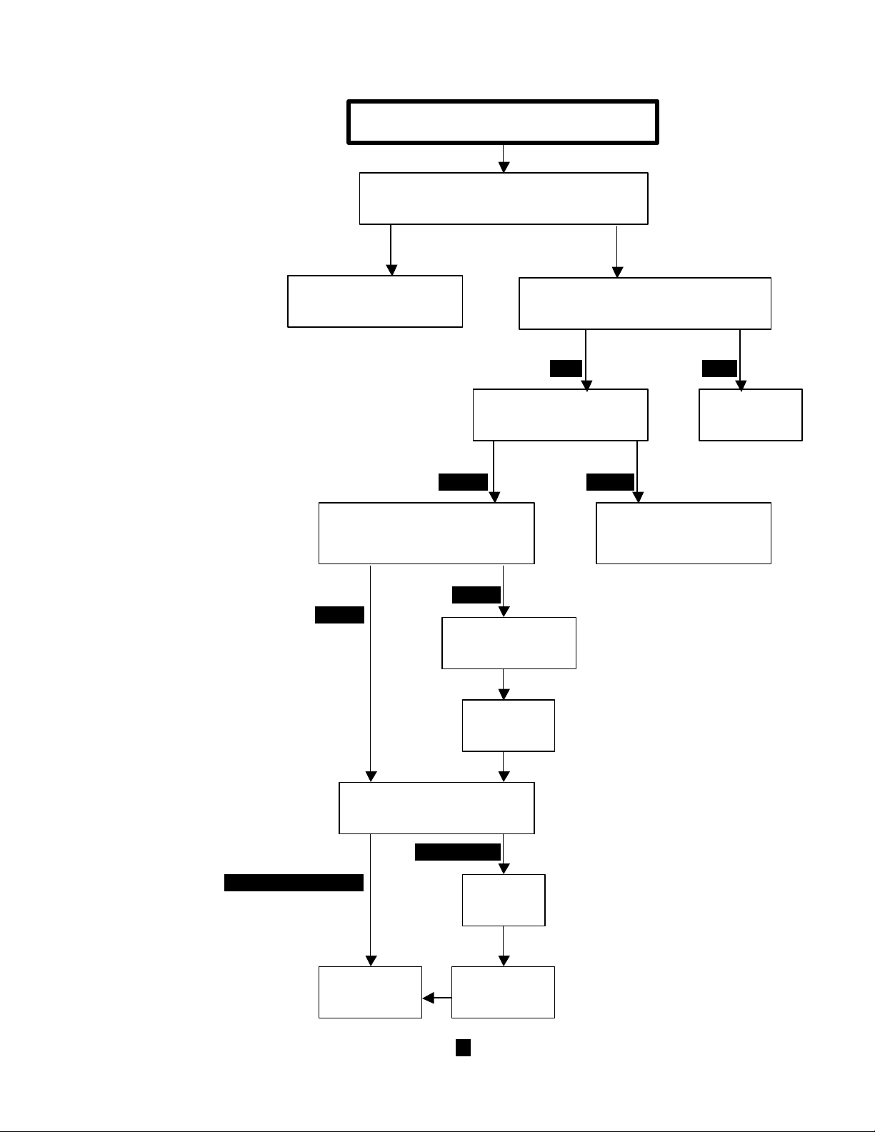
SERVICING COMPONENTS
MOTOR WILL NOT RUN
set to 0 minutes 0 seconds?
requirements
Yes
across terminals ARM+ and
ARM- on Speed Controller?
Yes
Yes
to Speed Controller
Microprocessor
No
Control in good condition
No
connection
No
determine why there is
no voltage to controller
Motor checks out OK
not running
output
Explained on Page 18
Motor Failed
Motor
not running
14
Page 18
SECTION
2
F. Troubleshooting Controller
AC AC
AC AC
Thumbwheel Setting
4 50 63 5 40 51 6 34 43 7 28 37 8 25 32 9 22 29 10 20 27 11 18 24 12 17 22
13
14
19
AC AC
15 110-120
Vac
NOTE: When changing conveyor speeds it is
advisable to first turn the Conveyor Switch OFF
before adjusting the thumbwheel switch.
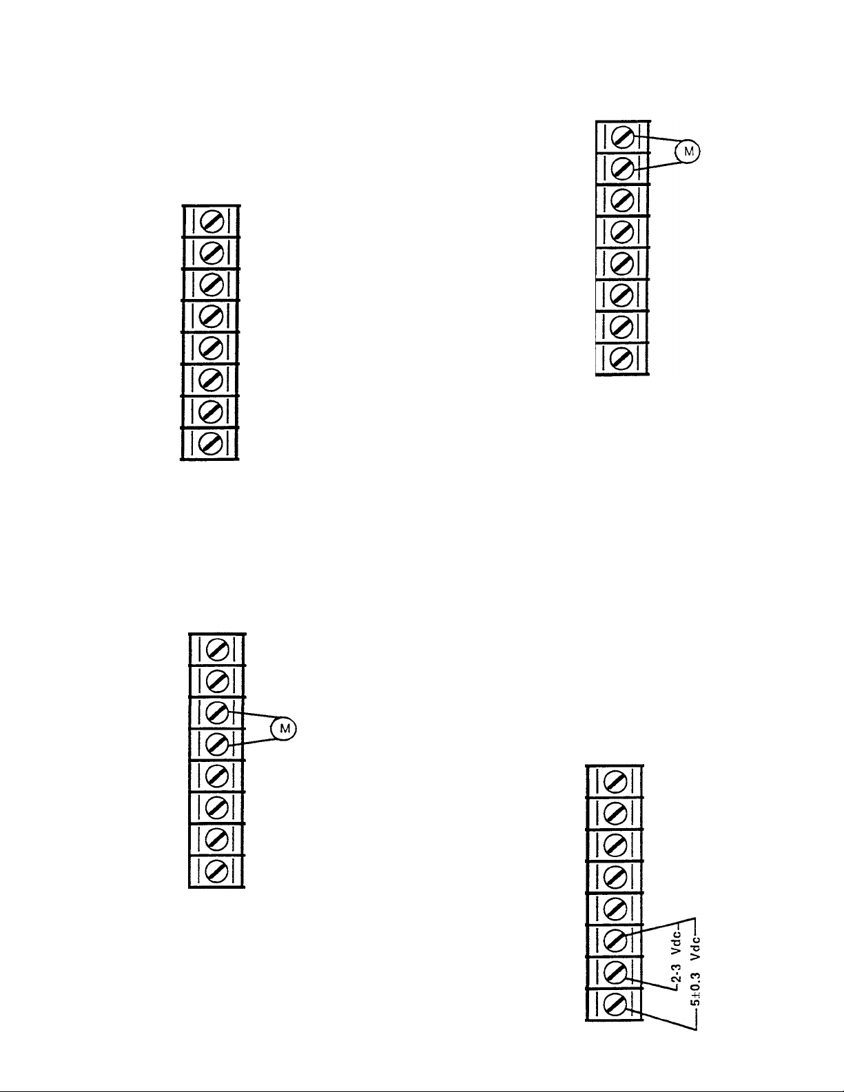
Step 1 - Check all connections at terminal board to
ensure connections are correct and tight.
Connections are as follows:
-ARM
+ARM
AC
AC
NO CONNECT
COM
RED
BLK
PINK
WHITE
BROWN OR BLACK
SERVICING COMPONENTS
with the voltages shown on the chart below. If the
voltage reading is more than ±5Vdc of that shown on
chart, complete motor test shown on Page 18.
-ARM
+ARM
NO CONNECT
COM
COUNT
+5V
Figure 8
COUNT
+5V
YELLOW OR WHITE
ORANGE OR RED
Figure 6
If wiring is not correct, make corrections are tight,
including connections on plugs and receptacles,
proceed to Step 2.
Step 2 - Ensure there is power to controller. Use a
Digital Multimeter to read voltage between the
terminal connections marked "AC" on controller.
Meter should read between 110-120 VAC.
-ARM
+ARM
NO CONNECT
COM
(Minutes)
3
15
DC Motor Voltage
PS310/360 PS200
67 84
13
18
Step 4 - Check Magnetic Pickup at back of motor. If the
pickup is in good condition as per Step 3, check the
voltages. Make sure conveyor is running. Using your
meter set at DC, check between COM and ±5 V. Voltage
should read +5 Vdc, ±0.3V. Next check between COM
and Signal (count). Reading should stay between 2 to 3
Vdc. If either of these two readings are incorrect, see
Conveyor Control Pickup Test on Page 17.
-ARM
+ARM
Figure 7
If power is not available, check power source.
If power is available, proceed to Step 3.
Step 3 - With the AC power on, check the DC voltage
to the conveyor motor and match the motor vottage
COUNT
+5V
NO CONNECT
COM
COUNT
+5V
Figure 9
Page 19

SECTION 2 SERVICING
27 23
COMPONENTS
G. Conveyor Control Check Using A
Frequency Counter
The following procedures are to be used ONLY if you
have a Frequency Counter feature on your Digital
Multimeter. If no Frequency Counter is available,
disregard this test procedure and go to Conveyor
Controller Pickup Test on the following page.
Using a Frequency Counter is the easiest and fastest
way to diagnose a problem with the speed control or
pickup.
We recommend you do your test at the 3, 6, and 10
minute thumbwheel settings before using the
following Troubleshooting Chart.
PS200
Thumbwheel Setting Vdc Frequency
(Minutes) to Motor
3.0 84 75
6.0 43 37
10.0
The charts to the right show the Thumbwheel setting
(belt speed) along with the corresponding DC voltage
and frequency reading. All readings should be plus or
minus 3 Vdc or 3 Hz of that stated in charts.
To measure the DC voltage output to gear motor,
place your meter leads across the speed controller
terminals ARM + and ARM -.
To measure the Pickup Feedback Frequency place
your Red (+) lead on the +5 Vdc terminal and the
Black (common) lead on the COUNT terminal.
TROUBLESHOOTING CHART
ARM (DC) voltage reading high but frequency is
correct.
ARM (DC) voltage reading is high and frequency is
zero. Also check for +5 Vdc and COM terminal on
speed control board. +5Vdc is present.
+5Vdc is not present ARM (DC) voltage reading is
high and frequency is high.
PS360
Thumbwheel Setting Vdc Frequency
(Minutes) to Motor
3.0 67 91
6.0 34 46
10.0 20 27
Replace Pickup
Replace Pickup
Replace Microchip. If still no change replace
speed control board.
Replace Microchip. If no change replace
speed control board.
Replace Microchip. If no change replace
ARM (DC) voltage reading is low but not zero and
speed control board.
frequency is low but not zero.
Replace Gear Motor.
ARM (DC) voltage reading is good and pulse is good
but motor not turning.
16
Page 20
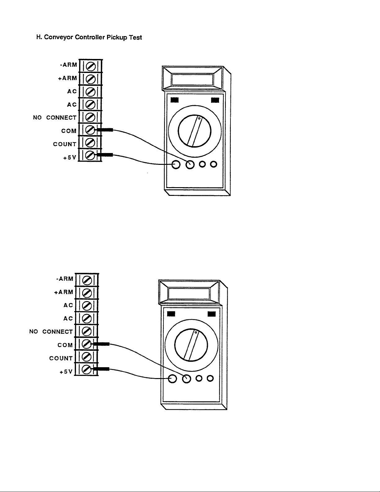
SECTION 2
Figure
10
SERVICING COMPONENTS
1. Visually check pickup for the
following:
• Magnet clean and bearing in
good condition.
• Chips or cracks on the
magnet.
• Old style pickup (not encased
in blue plastic housing) has a
1/64 to 1/32 gap between
magnet and hall device.
2. Set voltmeter on Volts DC
scale then connect meter
probes as shown. Black (- corn.)
probe to COM terminal on
speed control board and Red
(+VQ) probe to +5V terminal of
speed control. +5Vdc should be
present at all times when
conveyor is operating. If 5 Vdc is
present go to Step 3. If 5 Vdc is
not present, disconnect the
three pickup wires (connect-ed
to COM. SIGNAL and +5V
terminals) and again check for
+5Vdc. If 5Vdc is present with
pickup disconnected, change
pickup. If 5Vdc is not present
change speed controller.
3. If ±5Vdc is present with
pickup connected to speed
control, connect volt meter red
(+) lead to signal terminal and
disconnect motor wires from the
- ARM and + ARM terminals.
Using a 5/16" open end wrench
on the motor pickup shaft very
slowly rotate motor shaft while
observing volt meter. Two (2)
changes from +5V to 0V should
occur for every one motor
revolution. If signal is always at
0V, go to Step 4. If signal is
always at 5V or changes more
than 2 times per revolution,
change the pickup.
4. If signal is always at 0 Vdc,
disconnect pickup signal wire
from speed control and check
for +5Vdc at signal terminal of
control. If +5Vdc is present,
change pickup. If 0 Vdc is
present, replace speed control.
Figure 11
17
Page 21
SECTION 2 SERVICING
COMPONENTS
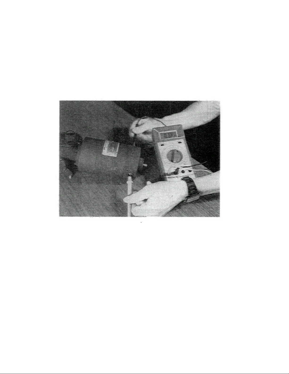
I. Conveyor Motor Test
1. Disconnect motor wires from Speed Controller terminals - ARM and + ARM.
2. Remove brush retainer caps. DO NOT remove the brushes.
3. Using an Ohm Meter (set to lowest scale) place one meter lead on each brush retaining plate Make sure
neither meter probe touches motor case.
4. Using a 5/16" open end wrench on the motor pickup shaft, very slowly rotate the shaft while observing the
Ohm Meter. There should never be a complete short 0 Ohm reading or a high Ohm reading during a 1/2
rotation. If either condition occurs, replace motor. The Ohm reading should stay between 3-5 Ohms.
Figure 12
18
Page 22
SECTION
2
SERVICING
J. Magnetic Pickup Replacement
When replacing magnetic pickup apply LOCTITE
REMOVABLE #242 sparingly on threads, turn
mounting screw until finger tight, then 1/4 turn more
with a wrench.
On rare occasions the speed control board on early
Model 360's may be affected by electrical noise
transmitted by other electrical components or
wiring. This noise is picked up by the speed
control's pickup wires and transmitted to the control
board. In most cases the conveyor will fail when
burner spark ignition is present. After ignition is
complete, turn the conveyor switch OFF and ON
and the controller should reset.
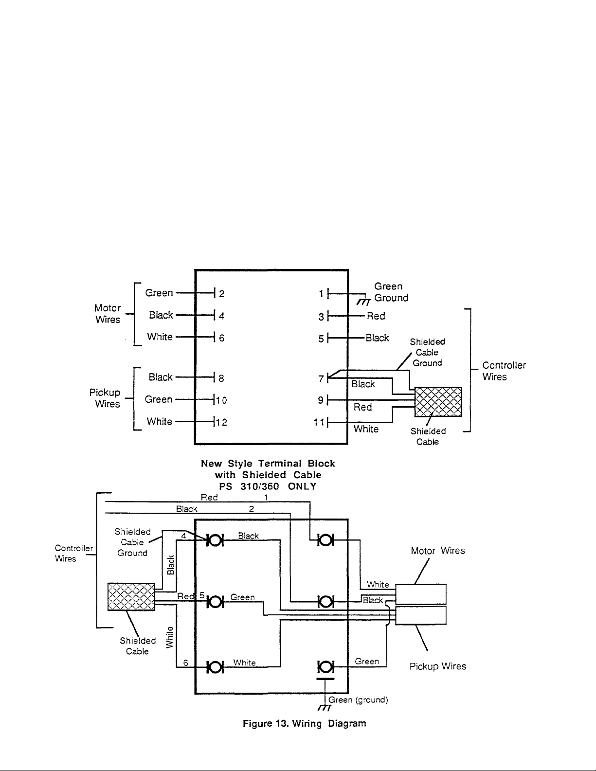
Old Style Conveyor Terminal Block-Located In Left
Blower Motor Compartment PS 310/360 ONLY
COMPONENTS
The permanent fix is to replace the pickup wiring
between the controller and terminal block (located in
left end motor compartment) with a shielded cable
MM/PN 42400-0334. When installing the shielded
cable follow the color code change shown below:
Old Wiring Shielded Cable
Brown Black
Orange Red
Yellow White
There will be a fourth lead on one end of the shielded
cable. This end always attaches to the terminal block
in the motor compartment. The extra wire lead is a
ground lead which is attached to the Black wire of the
shielded cable. Newer Model 360's have shielded
cable from factory. See diagrams in Fiaure 13.
19
Page 23
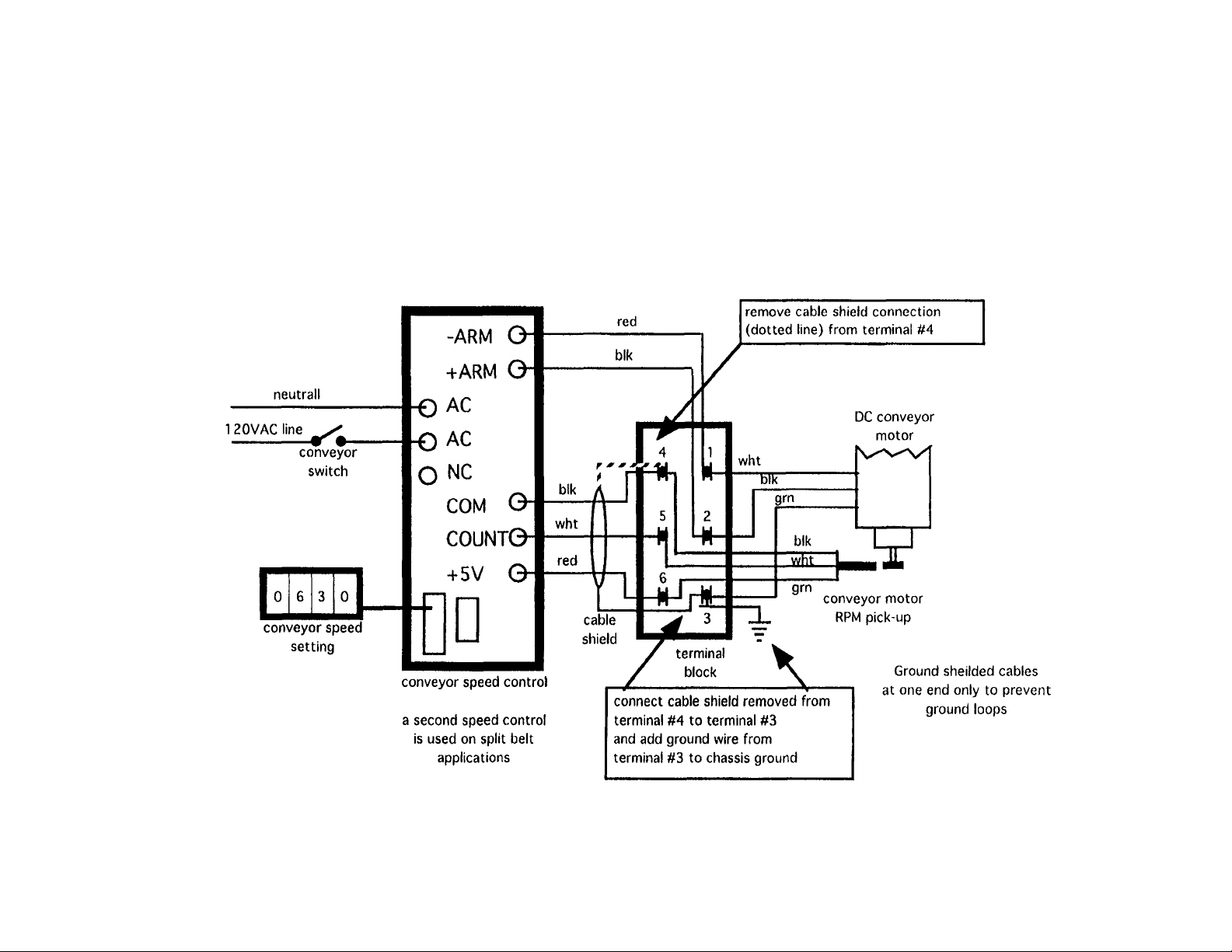
PS360 and PS570
conveyor sensor wiring changes
10/3/95 TRM
Page 24

Application
Subject
Bulletin No. MM-133B
Date 04/07/95
Middleby Cooking Systems Group
1400 Toastmaster Drive • Elgin, Illinois 60120 (708)741-3300 •
Service & Parts (708) 741-4406
Service Bulletin
Installation and Diagnostic Instructions DIP
Switch Conveyor Control Assembly Part
Number 42810-0133
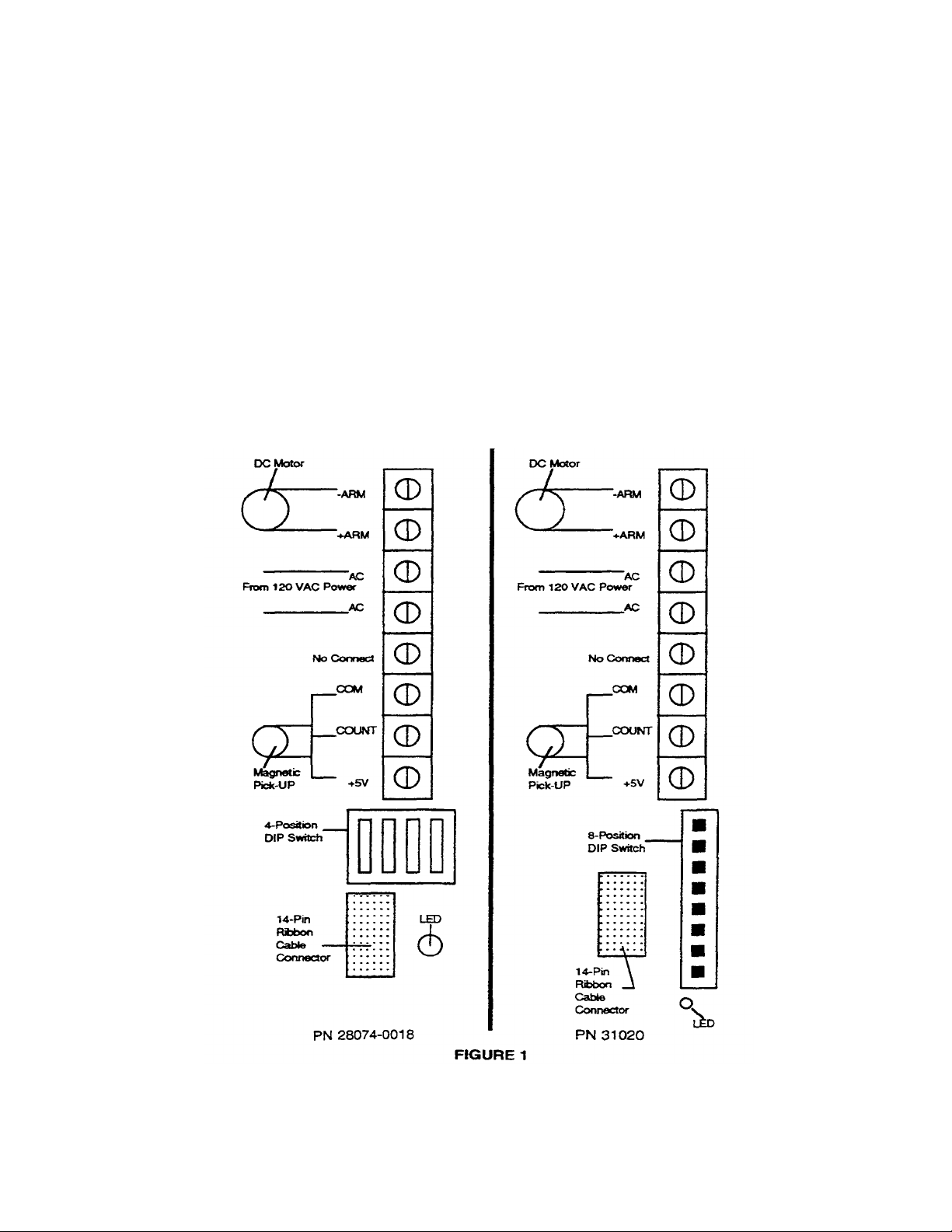
This service bulletin describes the original DIP switch conveyor control. Part Number 28074-0018, the new
DIP switch conveyor speed control, Part Number 31020 and introduces the latest instructions for installation
and set up- Either control can be contained in Kit Part Number 42810-0133. Both controls use advanced
digital electronics to improve reliability and provide diagnostic features. The installation and operation of
these controls are identical to each other and both replace prior non-DIP switch model controls.
Both control's printed circuit boards are housed in metal covers and both have
detachable/replaceable and interchangeable thumbwheel switches.
The distinguishing features between the original and the current control are the DIP switch
blocks and the markings on their metal covers.
Control PN 28074-0018 has a 4 position DIP switch and the control PN 31020 has an 8 position DIP
switch. Control PN 31020 has its individual DIP switch program settings silk screened on the metal
cover for easy reference.
Features
1. Control Part Number 31020 has enhanced tolerance to electrical systems that have
unstable frequency control (50 or 60 cycles). This control also continuously monitors the cycles
and adjusts itself accordingly. If an unstable frequency utility is common to the area, it is
recommended to use the PN 31020 control.
2. All DIP switch Conveyor Speed Controls provide a variable DC voltage output determined by the
thumbwheel setting and the frequency input from the speed control pick-up assembly.
3. DIP switch control PN 28074-0018 (REV. B)* and DIP switch control PN 31020
contain the program settings for all Middleby Marshall Ovens that use digital conveyor controls.
4. Both controls have built-in diagnostics to assist the service technician.
19B
Page 25

Features Continued
5. Both controls are protected against gear motor shorts.
6. Both controls have metal housing covers that guard against handling damage and
minimizes radio frequency interference (RFI).
•Note: Control PN 28074-0018 REVISION B contains all current DIP switch settings currently used in the
field. Prior to REV B. this control was not compatible with the 570 Series conveyor chain driven ovens. The
revision letter is printed on the controls label should you be concerned if your inventory is not updated.
Compatibility
Both the above referenced controls are compatible with all current and previous Middleby
Marshall digital conveyor controls, gear motors and pick -ups. Consult the gear motor/sprocket
combinations chart - contained in the attached instructions - for optional conveyor speed set ups.
The replacement thumb wheels used on both DIP switch controls can be interchanged.
Availability
All orders for replacement controls will be filled with control PN 31020. All newly manufactured
ovens are fitted with control PN 31020. Continue to order replacement controls under kit PN
42810-0133 which will contain the attached updated instructions along with control PN 31020.
19C
Page 26
DIP Switch Conveyor Control Installation and Diagnostic Instructions
Part Number 88210-0077 General
The following provides instructions for the Installation and Diagnostics of the DIP Switch Conveyor Control Part
Number 28074-0018 or Part Number 31020 contained in kit Part Number 42810-0133. Either of these controls
can be installed into the PS200, 300, and the 500 Series Ovens. Note: If installing PN 28074-0018 control into a
PS570(S) chain driven conveyor oven, be sure the control is marked "Revision B" on the label.
A. DIP Switch Conveyor Control Installation
The DIP Switch Conveyor Control Module is installed and secured with Phillips Head Screws and External Tooth
Lockwashers (not supplied) in the oven control compartment. The Thumb Wheel is installed in a rectangular
opening on the oven front panel. The ribbon cable from the Thumbwheel is connected to the 14-pin connector on
the control module.
Terminals on the specific control are arranged and marked to show electrical connections (See Figure 1). Consult
the specific oven model wire schematic for further wiring details especially for magnetic pick - up wire color
codes. The oven application must be selected by setting the "DIP" switches on the specific control to the proper
positions. The LED is used for diagnostics.
19D
Page 27
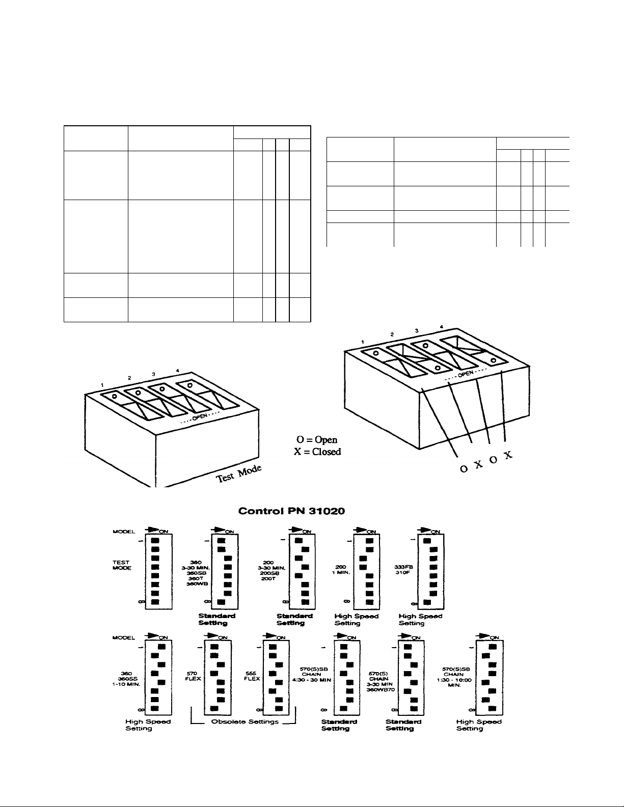
DIP SWITCH SETTINGS
Standard Conveyor Speed Settings
FOR BOTH CONTROLS
Control PN 28074-0018 (REV. B)
SWITCH SETTING
MODEL(S) OVEN TlMES(MlN/MAX) 1 2 3 4
PS200
PS200SB
PS200-20 PS224 2:40 M1N TO 29:50 MIN x 0 x x
PS200T
PS360
PS310
PS350 2:40 MIN TO 29:50 M1N 0 x x x
PS360SB
PS360T
PS360WB
PS570 PS570S 2:40 MIN TO 29:50 MIN 0 x x 0
PS360WB70
PS570-SB 4:30 M1N TO 30 MIN
PS570S-SB EXTENDED BAKE x x x 0
High Speed Option Conveyor Settings
SWTCH SETTING
MODEL(S) OVEN TlME(MtN/MAX) 1 2 3 4
PS200
(1 MIN) 40 SEC TO 10 MIN 0 0 x X
PS333FB 1:30 MIN TO 10 MIN x x 0 X
PS310F
PS360SS 1 MIN T010 MIN 0 x 0 X
PS570-SB HIGH SPEED OPT.
PS570S-SB 1:30 TO 10 M1N x 0 X 0
FIGURE 2
19E
Page 28

B. Replacement Thumb Wheel Switch Installation
1. Disconnect the power to the conveyor control by turning the conveyor switch to the "off' (0) position and
additionally by turning off the main power disconnect to the oven.
2. Remove the two screws that secure the failed switch body to the control door. Remove the switch body from the
door.
3. Locate the ribbon cable connector that links the thumb wheel switch to the controller. Note the orienta tion of the
cable for replacement. Grasp the connector frimly and pull it away from the control.
4. The thumb wheel connector is a polarized interlocking type connector that can only be installed in the correct
orientation. Locate the connector to the terminal strip so that the polarized interlocking lug on the connector is
aligned with the mating slot on the terminal and use your thumb to press the connector firmly into the terminal.
5. Locate the switch body to the control panel and assemble the switch body to the panel using the screws from
step 2.
6. Set the switches on the control to "diagnostic mode" in Figure 2.
7. Run diagnostic tests to determine performance to the control, (see diagnostic instructions below)
8. Set the mode switches back to the correct settings for the oven type and control version (see switch setting
instructions in Figure 2.
C. Diagnostics (Test Mode)
To assist the service technician, both controls feature built -in diagnositic software. Most of these diagnostic routines
are accessed by setting the dip switches to the test mode setting and then by powering up the conveyor control.
Also, certain conditions can be diagnosed by observing the red LED during normal operating conditions. Refer to
figure 2 to identify the control and test mode.
These test features are in addition to the diagnostic pr ocedures depicted in the applicable oven technical manual.
Note: Control PN 28074-0018 Test Mode setting is applicable to diagnosing 300 Series ovens and single belt 570
Series ovens only.
1. Diagnostics With Control In Normal Running Mode
If the red LED is lit and the control is not working (0 volts DC output at ARM then the gear motor short circuit
protection feature has been enabled.
Service the gear motor to correct the cause of the short circuit, then cycle the A.C. power switch to the conveyor to
restart the control.
19F
3
Page 29

Diagnostics With Control in Test Mode
4
The control in this mode provides a fast and convenient method of troubleshooting the control. When running the
diagnostic procedure the entire procedure must run or the control must be powered down and reset. There is no
option to perform individual tests.
1. Turn the conveyor power switch off.
2. Set the thumbwheel switch to 00:00.
3. Open the control panel door.
4. Set the control DIP switch to test mode.
5. Pull out the control box door safety switch so that the power will be on at the controls.
6. Turn the conveyor power on; CAUTION: The control will automatically start and operate the conveyor, make
sure that the conveyor drive mechanism and the conveyor path is not obstructed.
Gear Motor and Sensor Test
The controller automatically operates the gear motor at three speeds: slow (for 10 seconds), medium (for 10
seconds), and high (for 10 seconds).
a) If the gear motor reverts to medium speed after 30 seconds and the LED on the controller is lit, the test passed
and gear motor operation is normal.
b) If the gear motor stops after 30 seconds and the LED on the controller is lit, this indicates a Pick-up failure.
c) If the motor stops in less than 30 seconds (does not complete the test cycle of 10 seconds each speed) and the
LED is lit, this indicates a gear motor failure.
Thumbwheel Test* Once the pick-up passes the sensor test, the gear motor will be automatically set to
mid speed.
Set the thumbwheel to 00:10, observe the LED for 5 flashes. Then set the thumbwheel to 00:20, observe the LED
again for 5 flashes. Repeat this procedure in: 10 increments up to :^0 waiting until the LED stops flashing between
each setting change.
Roll the switch setting back to 00:00 then repeat the procedure using the minutes switch up to 09:00 minutes. Roll
back the thumbwheel to 00:00 and repeat the procedure for the 10's segment up to 20:00.
Upon successful completion of this test the test sequence will automatically repeat itself starting with the 30 second
motor test. The service routin e can now be repeated or the control can be returned to the normal operating mode. Be
sure to change the DIP switch back to the correct oven position before operating the oven.
*The LED located at the bottom right comer of the control will indicate the thumbwheel test results (pass/fail). Pass is indicated by five flashes of the LED at 1
second intervals followed by the LED remaining lit. failure is indicated by the LED remaining lit with no flashing. The LED must be observed after each
setting change.
19G
Page 30

D. Gear Motor/Sprocket Combinations
5
The chart reference below lists the different motor sprocket combinations used with the DIP switch conveyor control
system.
CONVEYOR MOTOR/SPROCKET COMBINATIONS
MODEL & CHAMBER GEAR MOTOR CONVEYOR BAKE TIME
LENGTH MOTOR SPROCKET SPROCKET PARAMETERS
PS200 40.5" 1350:1 Ratio 15T 10T 2:40 Min to 29:50 Min
PS220FS 27384-0011 22151-0003 22151-0002
PS224
(Standard)
PS200T 81" 1350:1 Ratio 30T 10T 2:40 Min to 29:50 Min
(Tandem) 27384-0011 22159-0004 22151-0002
PS200 1 Min 40.5" 311:1 Ratio 15T 10T 40 Sec to 10 Mm
(High Speed) 27384-0014 22151-0003 22151-0002
PS200SB 40.5" 1350:1 Ratio 30T 20T 2:40 Min to 29:50 Min
(Split Belt) 27384-0011 22159-0004 22159-0003
PS360 54.5"
PS310
PS314 1400:1 Ratio 15T 9T
PS360SB 27384-0008 22152-0018 22152-0017 2:40 Min to 29:50 Min
PS360WB
PS350
(Standard)
PS360WB70 70" 1400:1 Ratio 15T 9T 2:40 Min to 29:50 Min
(Wide Body Stretch) 27384-0008 22152-0018 22152-0017
PS360SS 54.5" 1400:1 Ratio 45T 9T 1 Min to 10 Min
(High Speed) 27384-0008 22152-0027 22152-0017
PS360T 109" 1400:1 Ratio 30T 9T 2:40 Min to 29:50 Min
(Tandem) 27384-0008 22152-0022 22152-0017
PS570 70" 1400:1 Ratio 15T 9T 2:40 Min to 29:50 Min
PS570S 27384-0008 22152-0018 22152-0017
(Standard)
PS570SB 70" 1350:1 Ratio 15T 9T 4:30 Min to 29:50 Min
(Standard) 27384-0011 22152-0024 22152-0017
PS570SB 70" 311:1 Ratio 15T 9T 1:30 Min to 10 Min
(High Speed) 27384-0014 22152-0024 22152-0017
19H
Page 31
II. TEMPERATURE CONTROLLER
The temperature controller used on PS200 &
PS310/314/360's has two major functions:
First on gas heated oven is to control the high flame
solenoid. The temperature controller has no effect on
the low flame or oven ignition system. On electrically
heated ovens it controls all the banks of elements.
The second function is to control the high temperature
safety limit and cooldown features. NOTE: This function
is not included in temperature controller's supplied with
electrically heated ovens. A separately located solid
state high limit/cooldown device is used.
A. A Honeywell (DiaIaPak) Controller Is The
Temperature Controller Used On The
PS200/310/314/360's.
Temperature Controller Party's:
Gas Ovens & Electrically Heated 380-480V
Ovens: MM/PN 28071-0018
All Domestic and Canadian Electrically heated
ovens, and all ovens 240V or less: MM/PN
28071-0012
SECTION 2 SERVICING
COMPONENTS
1. General Description
Dialapak instruments consist of two primary
assemblies: the case and the plug-in chassis.
The molded plastic case assembly houses the
plug-in chassis and provides terminals for field
wiring connections. A U-shaped bracket around
the case allows the instrument to be panel
mounted. The plug-in chassis consists of a front
assembly and two printed circuit boards.
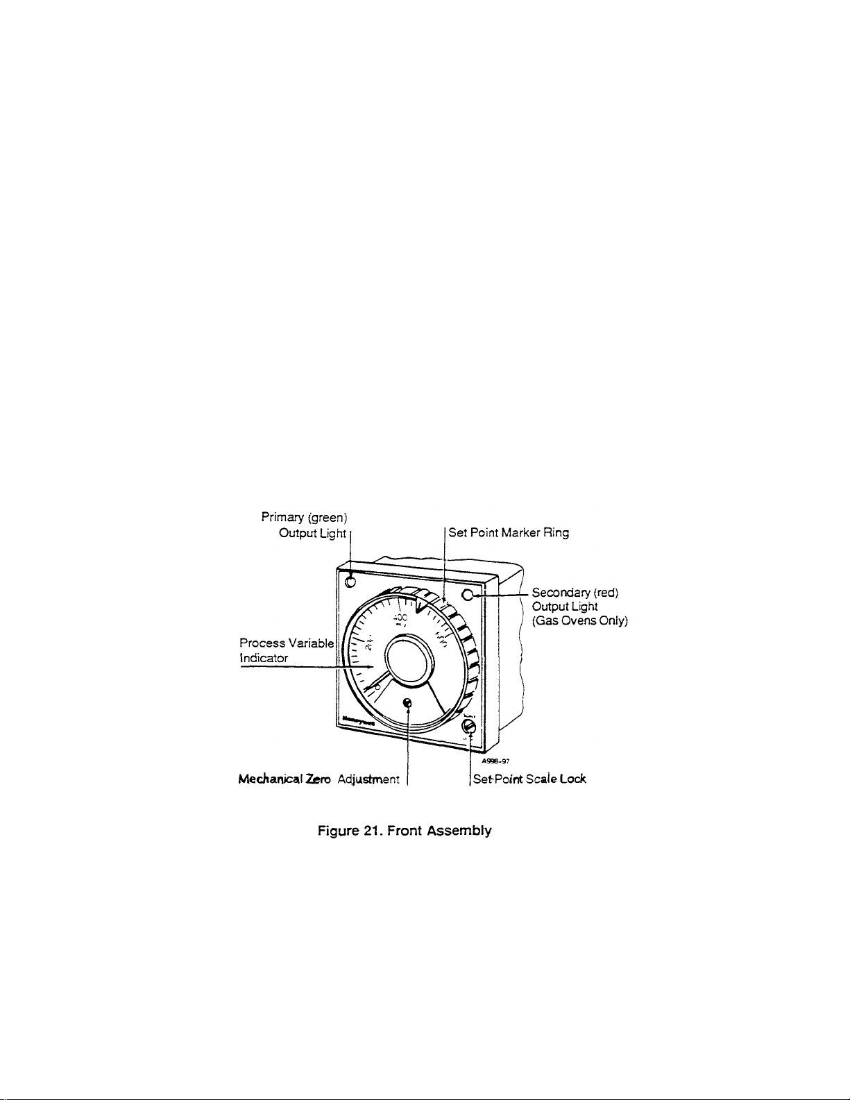
Indicator - The front assembly contains a
circular-scale, process variable indicator; a
mechanical zero adjustment for the indicator; a
movable ring around the circumference of the
indicator for marking the set point of the process
at a scale position; a screwdriver operated scale
lock that secures the movable ring at a given
scale position and a green primary output light.
NOTE: Later model meter face shows both degrees
Fahrenheit and degrees Centigrade.
23
Page 32
SECTION 2 SERVICING
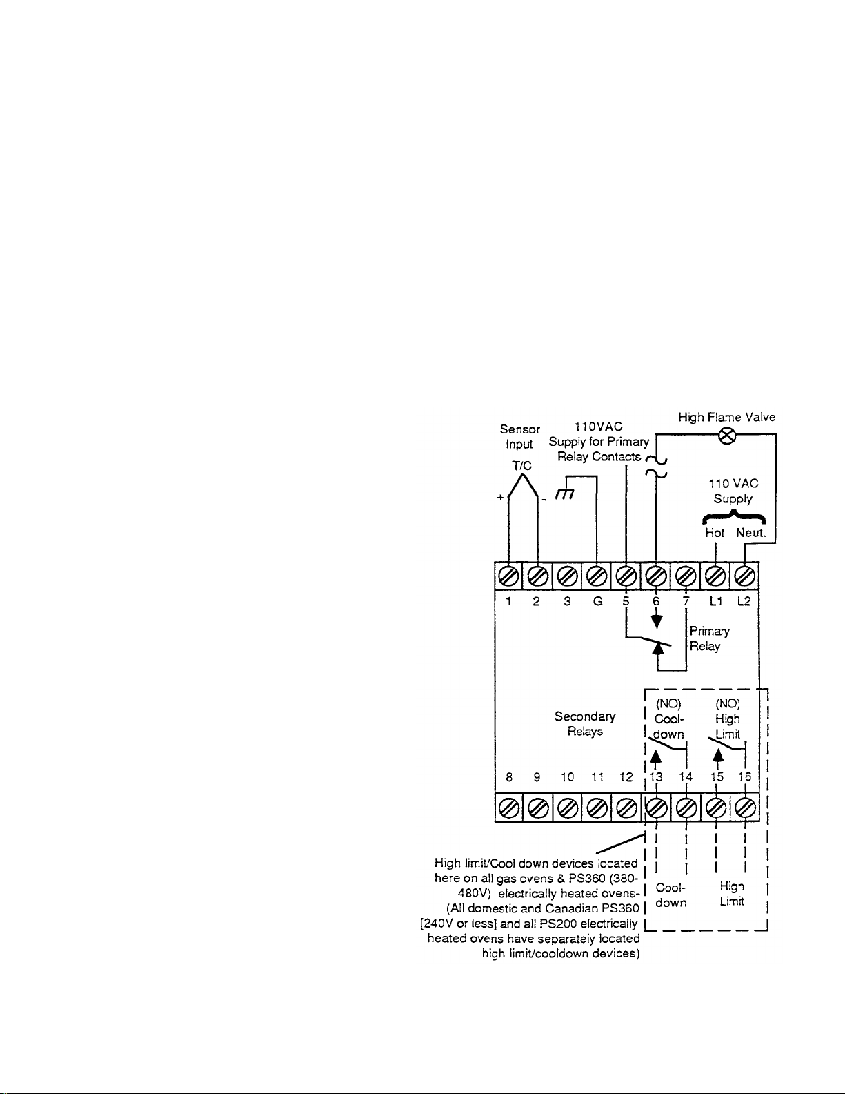
Figure
24.
Temperature Controller Wiring
COMPONENTS
f. Check that the meter is indicating the value
of the process variable (oven temperature).
g. High Limit and Cooldown Alarm
This circuit provides means to actuate external
high and low alarm circuitry when the process
deviates from the primary set point in either
direction. It also provides local indication when
an alarm state is in progress.
The High Limit/Cooldown circuit includes two
electromechanical SPST relays. The N.O.
contacts of both relays terminate at the rear of
the instrument for field wiring connections. A
red LED visible from the front indicates the
status of both relays. The error signal from the
differential amplifier controls the operation of
these relays. Both relays are energized and
the red LED is off when the PV is within the
low-high alarm band. If the PV falls below the
low alarm set point, or exceeds the high alarm
set point, the respective relay is de-energized
and the red LED is turned on.
4. Upscale Burnout Option
This unit is equipped with an upscale burnout
option, which is a form of sens or break protection
which drives the instrument to maximum upscale
value in the event of an open circuit in the sensor
or sensor leadwire. On heating applications, this
feature simulates a high temperature condition,
shutting down the heating system to prevent
damage due to high temperature.
g. Analog Set Point (see Figure 24).
The analog set point is established through a
potentiometer adjustment by turning a ring
(set point dial) around the front panel scale.
The set point can be set over the entire
calibrated scale length. The set point dial is
connected directly to the set point pot wiper
for precise and accurate setting. A
screwdriver-operated set point dial lock
prevents accidental or unauthorized
changes in its setting.
NOTE: The temperature in baking chamber may be
approximately 20° to 40° lower than indicated on
temperature dial because of the location of the
thermocouple.
5. Adjustments
Controller Model AV30 Set Point Version
a. Make sure that the meter pointer is on zero.
Gently tap the meter face for optimum reading.
Use the mechanical zero adjustment on the
face of the meter to align the point with the
scale, if necessary.
b. Turn the primary set point ring until its index
is aligned with the scale marking that
corresponds with the desired primary set point
of the process.
c. Turn the scale lock clockwise to lock the set
point ring in place.
d. Apply the operating power to the
instrument.
e. Check that the green primary output light
turns on when the controller output is actuated
to manipulate the controlled variable.
Diagram
26
Page 33
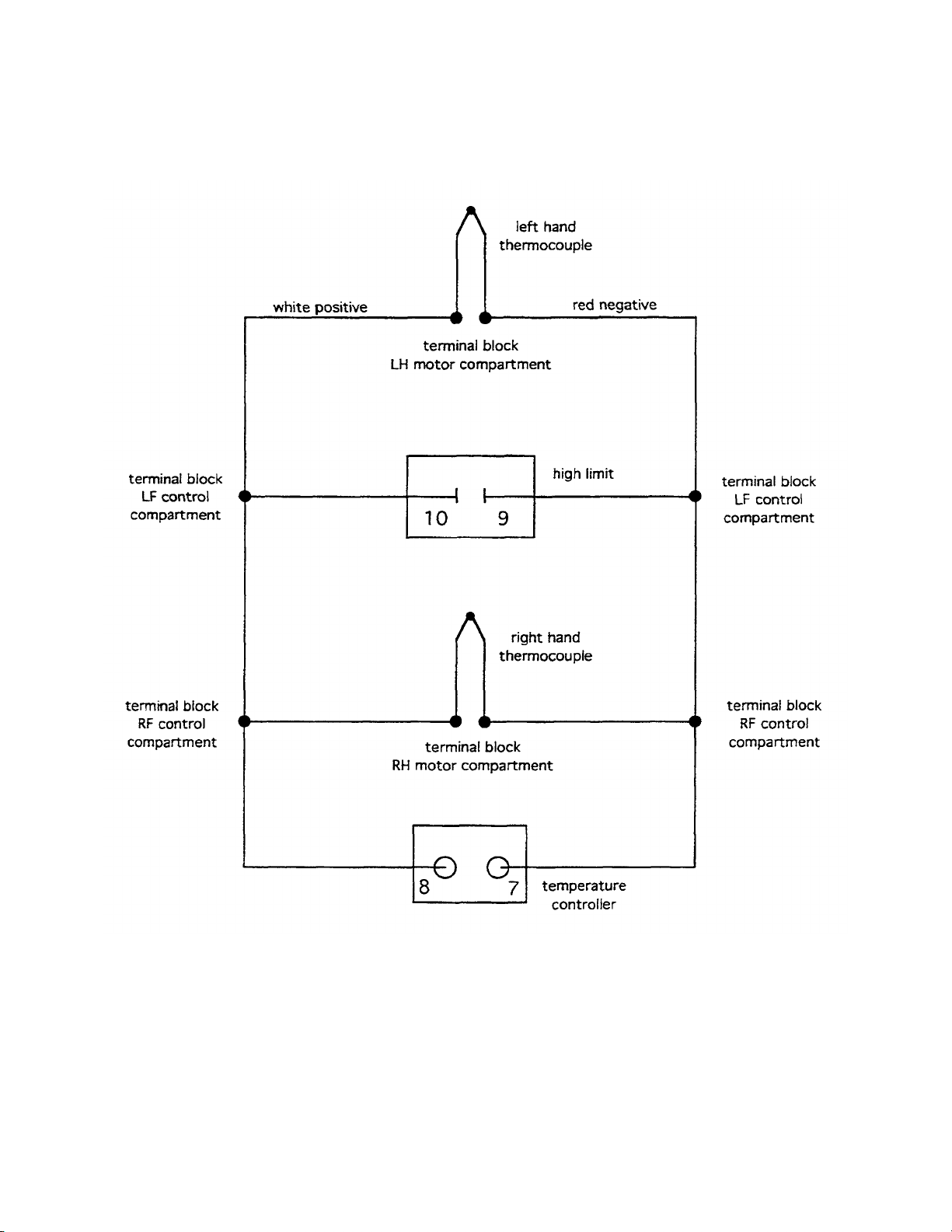
PS570S thermocouple wiring
26A
11/6/95 TRM
Page 34

TROUBLESHOOTING HONEYWELL
TEMPERATURE CONTROLLER
Meter Inoperative Defective AC power
supply
Meter at or near zero Open input circuit.
at al times (models Open meter or circuit
without burnout) board connections
to front assemblyMeter Upscale Open sensor circuit.
(upscale burnout Open compensator
models) (T/C models).
The following chart lists the thermocouple millivolt readings from 200°F (93°C) to 600°F (315°C):
SECTION 2 SERVICING
COMPONENTS
B. Thermocouple (Type J)
When two wires composed of dissimilar metals are
joined together and one of the ends is heated, a
continuous current flow is generated. We use an
iron contant (Type J) thermocouple. The iron wire
increases the number of dissimilar metal junctions in
the circuit-If the thermocouple is open, the
temperature controller will read very high, (full scale)
on the temperature controller.
It is possible to check a thermocouple with a
properly calibrated D.C. millivolt meter. At 32° F. (0°
C.) the millivolt reading should be 0.00. This can be
checked by inserting the thermocouple into an ice
bath.
The millivolt reading at 72° F. (22° C.) should be
1.134.
When using the chart shown below the temperature
at the teminal connections must be noted. This
temperature is called the Junction Temperature.
90°F(32°C) 3.26 4.77 6.30 7.06 7.83 9.37 10.14 10.91 12.46 14.00 15.53
J
U
88°F(31°C) 3.32 4.83 6.36 7.12 7.89 9.43 10.20 10.97 12-51 14.05 15.59
N
C
86°F(25°C) 3.37 4.88 6.41 7.17 7.94 9.49 10.26 11.03 12.57 14.11 15.65
T
84°F(29°C) 3.43 4.94 6.47 7.23 8.00 9.54 10.31 11.09 12.63 14.19 15.71
1
0
82°F(28°C) 3.49 5.00 6.53 7.29 8.06 9.60 10.37 11.14 12.69 14.23 15.76
N
80°F(27°C) 3.55 5.06 6.59 7.35 8.12 9.66 10.43 11.20 12.74 14.28 15.82
T
78°F(26°C) 3.60 5.11 6.64 7.40 8.17 9.72 10.49 11.26 12.80 14.34 15-88
E
76°F(24°C) 3.66 5.17 6.70 7.46 8.23 9.77 10.55 11-32 12-86 14.40 15.94
M
P
75°F(24°C) 3.69 5.20 6.73 7.49 8.26 9.80 10.57 11.35 12.89 14.43 15.97
E
R
74°F(23°C) 3.72 5.23 6.76 7.52 8.29 9-83 10.60 11.37 12.92 14.46 15-99
A
72°F(22°C) 3.78 5.29 6.82 7.58 8.35 9.89 10.66 11.43 12.97 14.51 16.05
T
U
70°F(21°C) 3.83 5.34 6.87 7.63 8.40 9.95 10.72 11.49 13.03 14.57 16.11
R
E
68°F(20°C) 3.89 5.40 6.93 7.69 8.46 10.00 10.78 11.55 13.09 14.63 16.17
66°F(19°C) 3.95 5.46 6.99 7.75 8.52 10.06 10.83 11.61 13.15 14.69 16.23
64°F(18°C) 4.01 5.52 7.05 7.81 8.58 10.12 10.89 11.66 13.20 14.74 16.28
62°F(17°C) 4.06 5.57 7.10 7.86 8.63 10.18 10-95 11.72 13.26 14.80 16.34
60°F(16°C) 4.12 5.63 7.16 7.92 8.69 10.24 11.01 11.78 13.32 14.86 16.4C
OVEN TEMPERATURE
200°F
93°C
250°F
121°C
300°F
149°C
325°F
163°C
350°F
177°C
400°F
204°C
425°F
218°C
450°F
232°C
500°F
260°C
550°F
288°C
600°F
315°C
Example: The thermocouple millivolt reading at 500°F
(260°C) with a junction temperature of 86°F (30°C) should
be 12.57 millivolts (mv).
27
Page 35
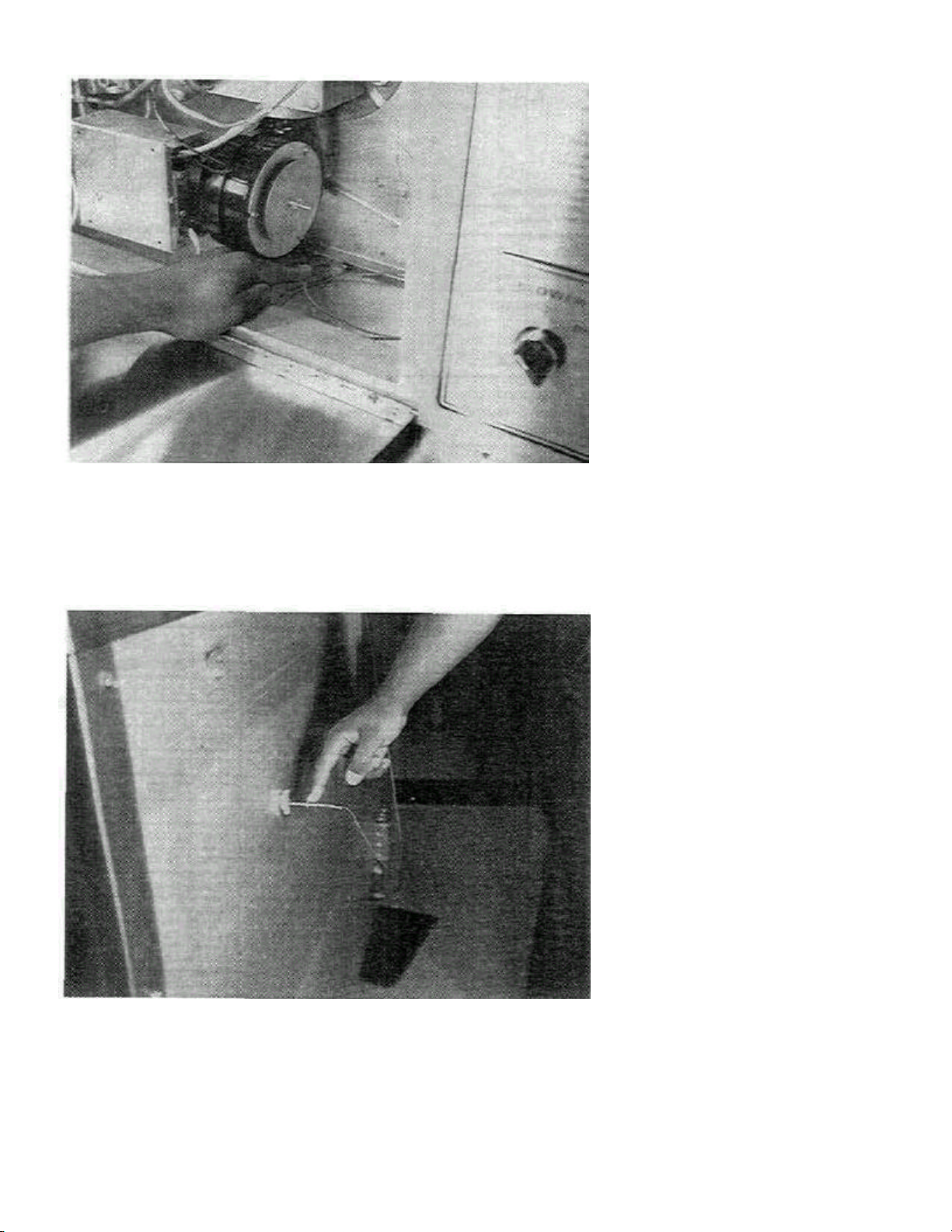
SECTION 2 SERVICING
1.
Thermocouple Installation
Figure
25.
Oven Thermocouple Installed Into Bake
On
PS360
ovens with thermo
couple
COMPONENTS
Models PS310/360 Only
The thermocouple on the PS360 was
mounted in two different locations over
time. Earlier models had the
thermocouple mounted through the
machinery compart ment behind the
burner blower motor (see Figure 25).
This would protrude the thermocouple
into the bake chamber and read the
return air going into the burner
chamber. To install, put a mark* 6-3/4"
from the tip of the thermocouple then
push the thermocouple into the baking
compartment sleeve until the 6-3/4"
mark is at opening of sleeve. The
tighten alien screw onto the
thermocouple and close up hole with
silicone seal.
*NOTE: All thermocouples are
shipped with a push nut at the back end
of the 7" sheath. Use the push nut to
mark the proper insertion point
Chamber
ports in the rear of the oven (see
Figure 26) (includes all PS360S and
PS360Q models), measure and mark*
6" back from the tip then slide the
thermocouple into the entrance side
port in rear of oven until the 6" mark is
on the outside of clamp as shown in
Figure 26. Tighten clamp, make sure
thermocouple is secure. This
location puts the thermocouple into
the rear air plenum which now
measures heated air from the burner
going directly into the fingers.
*NOTE: All thermocouples are
shipped with a push nut at the back
end of the 7" sheath. Use the push
nut to mark the proper insertion point
Figure 26. Oven Thermocouple Installed Into
Rear Oven
28
Page 36
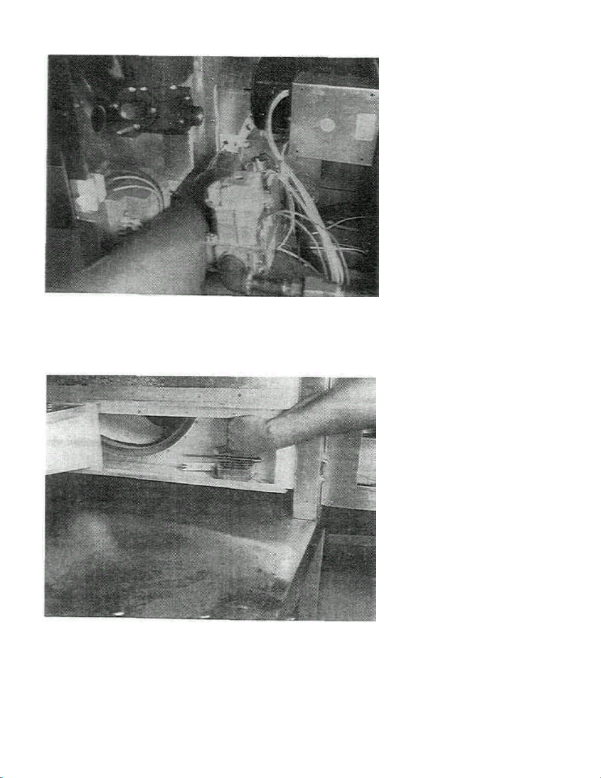
Figure 27
Figure
28
shows thermocouple
Figure
28
29
SECTION 2 SERVICING
COMPONENTS
2. Thermocouple Installation
Model PS200 Only
Figure 27 shows the insertion point for
the thermocouple inside the
control/machinery compartment. All
thermocouples are shipped with a push
nut at the back end of the 7" sheath.
This push nut must be removed when
installing thermocouples in a PS200.
NOTE: On electrically heated ovens a
dual lead thermocouple is used. One
lead connects to the Temperature
Controller and the other lead to the
separate high limit/cooldown devi ce.
properly inserted with the tip 3-1/4"
(83mm) from end of sleeve. The set
screw must be tightened after
installation of thermocouple.
Page 37
SECTION 2 SERVICING
COMPONENTS
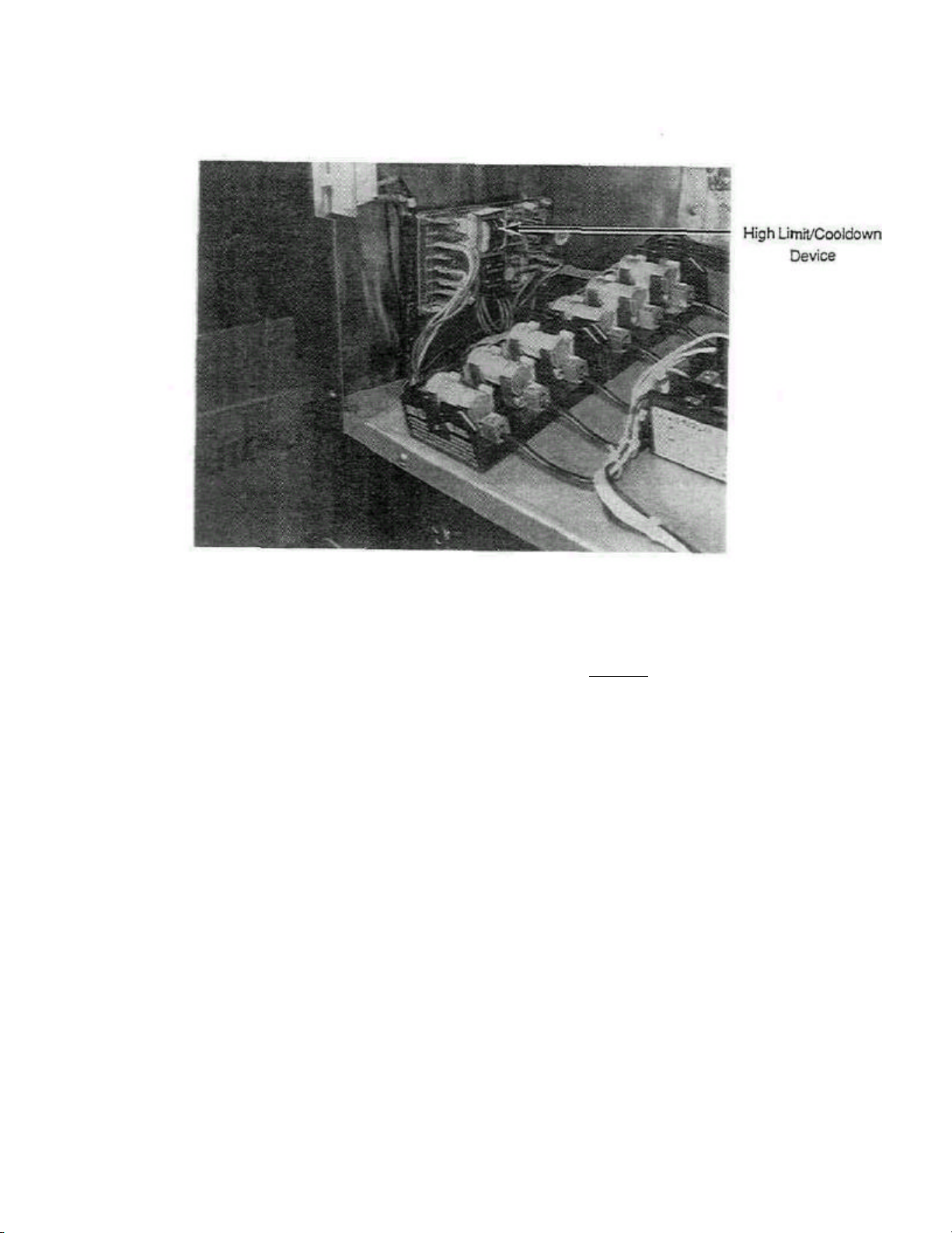
Figure 29. Electric Oven High
Limit/CooIdown Device (Shown in
C. High Limit/CooIdown Switch
Both the High Limit and Cooldown Switches are
incorporated into the secondary P.C. board of the
Temperature Controller on gas ovens. On electrically
heated ovens the high limit/cooldown device is
located separately - external of the temperature
controller as shown in Figure 29. The High Limit will
shut the oven (heat) off if the temperature goes over
650° F. (343° C.). The Cooldown feature allows the
operator to turn all Control Switches off, then the Low
Limit Switch will keep the blowers operating until the
oven has cooled down to 180° F. (82° C.) at this point
the oven will shut down.
If the Burner and Heat Switch are on and the oven
temperature goes below 180° F. (82° C.) or above
PS200)
650° F. (343° C.) the red LED, located in the upper
right corner of gas oven Temperature Controller
face, will be lit. This red LED will also remain on at
startup until the oven climbs above 180° F. (82° C.).
NOTE: Electric ovens have no indicating light for
high limit/cooldown.
With the oven in the cooldown mode the dial will
continue to record oven temperature until 180° F.
(82° C.) when the Cooldown Switch opens and shuts
all power to blowers and temperature control.
See Figure 24 for terminal connections for the Low
and High Limit Switches on the Temperature
Controller.
30
Page 38
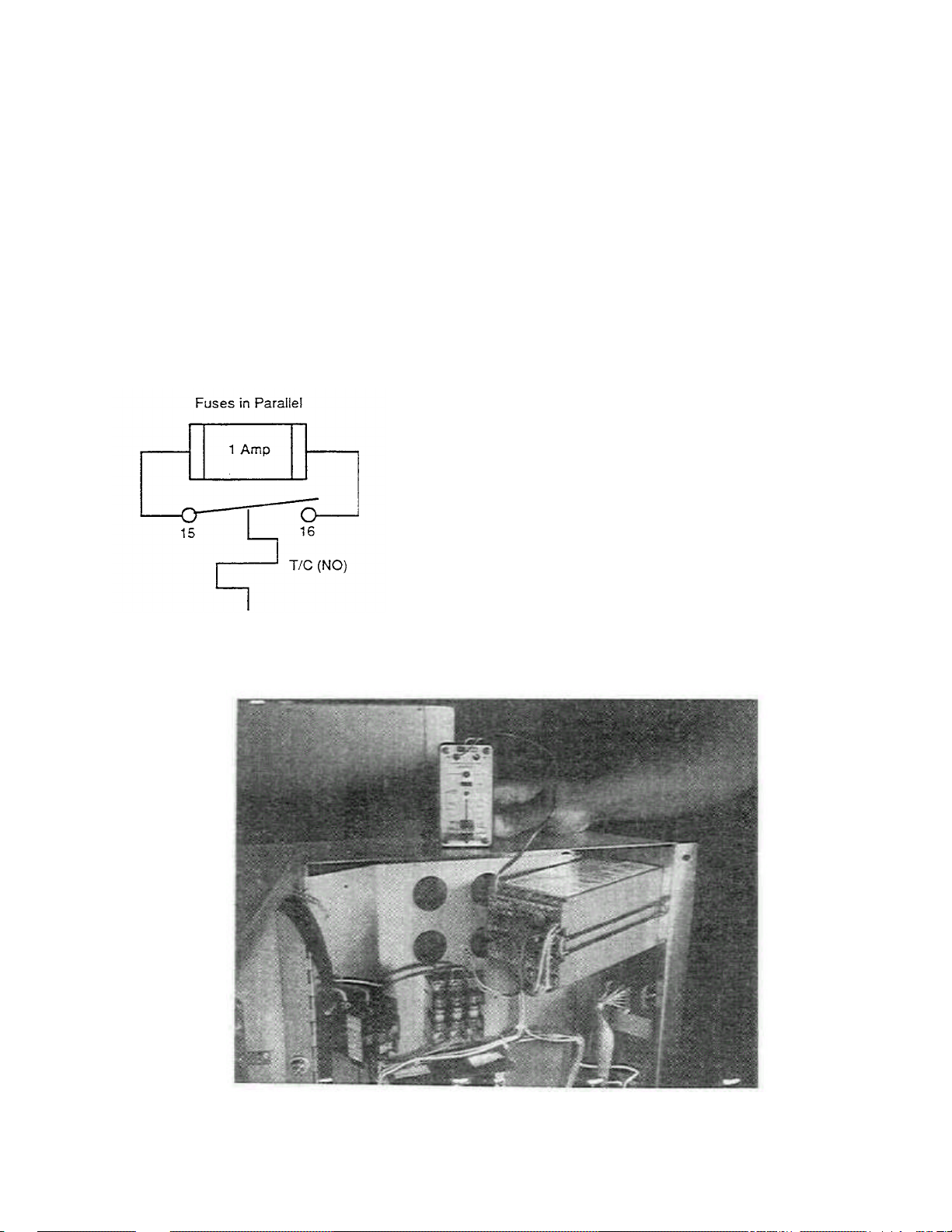
D. Troubleshooting Limit Switches
An intermittent High Limit Switch will cause
intermittent operation of the burner. If you suspect
an intermittent opening of this Switch a good check
is to place a 1 amp fuse in parallel around the
Switch contacts (see Figure 30).
if the Switch is trying to open intermittently the full
current load of the Blowers will be carried by the
fuse. Since this load will be much greater than 1
amp the fuse will blow. This would be an indication
of a bad Switch. If the Switch is good the fuse would
not blow as the only time the Switch would open
would be under a no load condition and the fuse
would never have to conduct current.
SECTION 2 SERVICING
COMPONENTS
E. Testing Procedure For Temperature Controller
Part 1. Testing The Temperature Controller (MIWPN
28071-0018), High Limit Switch and Thermocouple
Using the Altek Testing Device (ATS).
The following tests may be performed in conjunction
with the ALTEK Type "J" Thermocouple Source
(MM/PN 27170-0192) to check Temperature
Controllers and Thermocouples.
IMPORTANT: The Temperature Controller is rated for
accuracy only up to 140° F. (60° C.) ambient, the
Controller must be allowed to cool before continuing.
Check the cooling fan and/or customer ventilation system
if the Control Box exceeds 140° F. (60° C.) with the
Control door closed.
1. Temperature Controller Check
a. Turn Heat Switch OFF.
b. Disconnect thermocouple wires from -1 and -2
terminals on Temperature Controller. Tape ends to
prevent shorting. Next connect white lead (+) of
the ALTEK Thermocouple Source (ATS) to
terminal -1 and the red lead to terminal -2. Set
ATS to temperature closest to customer set point
on controller. Turn blower switch ON.
Temperature Control should read within 5° of
ATS setting.
Figure 30. High Limit Switch
Figure 31. Altek Shown Connected to
Temperature Controller (PS200 shown)
Page 39
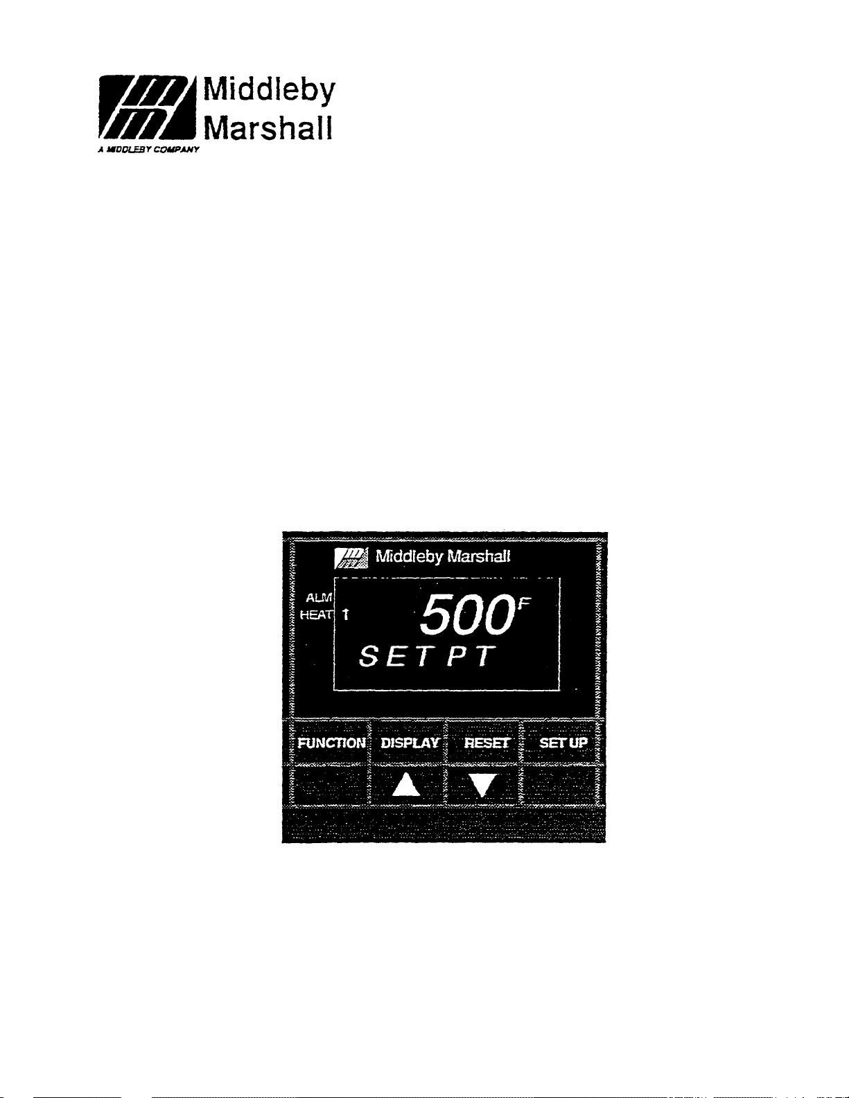
31B
Part No. 88210
-
0079
Digital Temperature Controller
(P/N 28071-0028)
Installation, Programming
and Troubleshooting
Instructions
Middleby Marshall inc. • •i400 Toastmaster Dr. • Elgin, IL 60120 • (708) 7^-33CO • FAX (708) 741-4406
Middlebv Corporation 24 Hour Service Hotline 1-800-238-8444
P3/93
Page 40
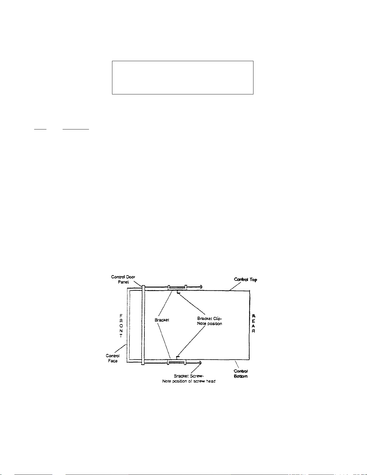
Mechanical Installation
1.04. The following provides mechanical installation instructions for the Digital Temperature Controller
CAUTION
Before installing the Digital Temperature Con
troller, shut OFF all electrical powerto the oven at
the disconnect switch or circuit breaker.
To remove the Analog Temperature Controller and install the Digital Temperature Controller, proceed as follows:
Step Procedure
1. Disconnect all associated wiring from the terminals located on the rear of the Analog Temperature
Controller. Disconnect and retain any jumper wire(s).
2. Remove two bracket screws and bracket securing the Analog Temperature Controller to the oven.
Slide the bracket away from the controller. Remove the controller by pulling it out through the front
side of the panel. Refer to Figure 1.
3. Insert the Digital Temperature Controller into the same panel slot making sure the face of the
controller is upright with the display on top and the push buttons on the bottom.
4. Identify the two rectangular holes on top and bottom of the control case. Attach the two panel
mounting brackets with the clips of the brackets and the head of the screws pointing towards the rear
of the new controller into these rectangular holes.
5. Tighten both screws evenly against the backside of control panel until the controller seats securely.
Figure 1 - Mounting Bracket Clip and Screw Position
31C
Page 41

Electrical Connections
NOTE
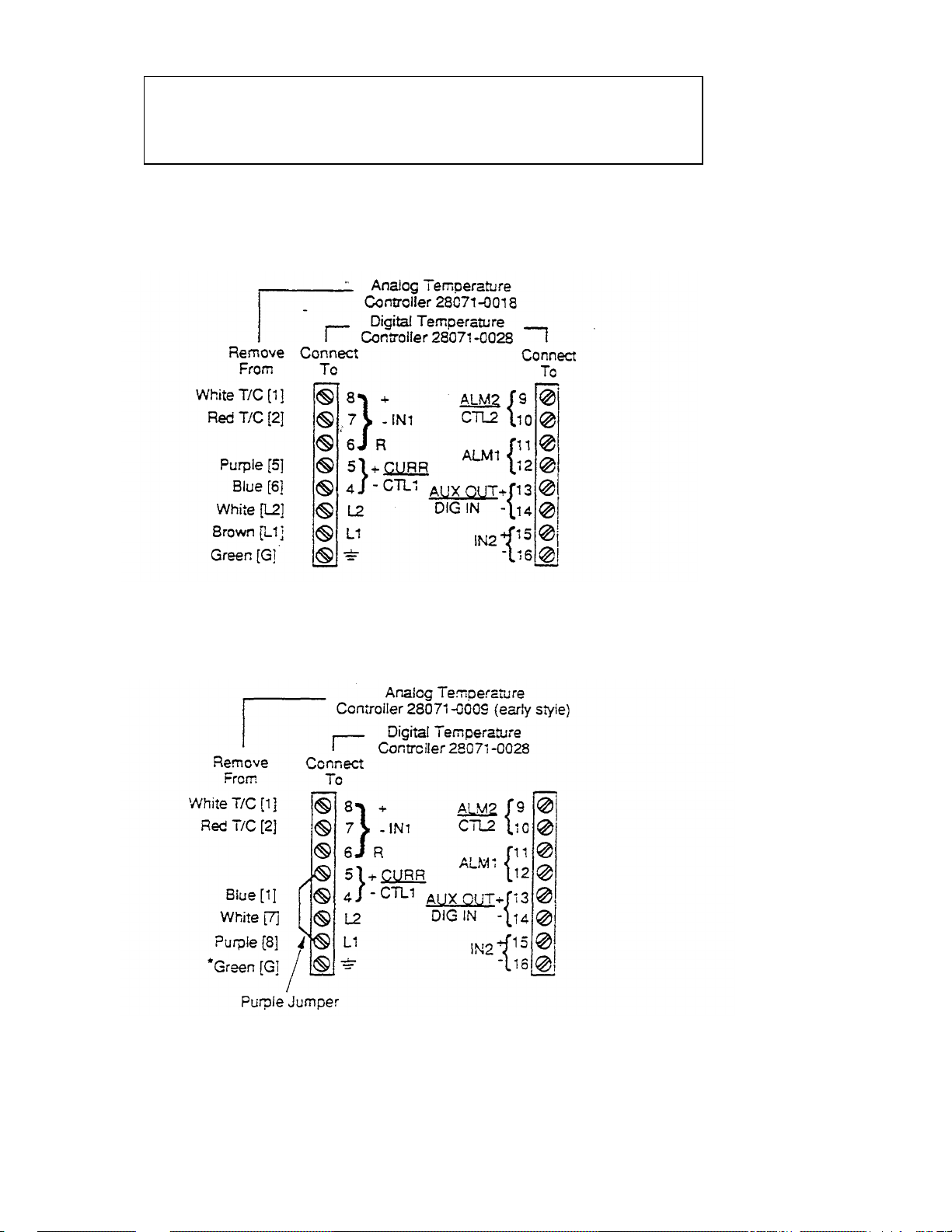
1.05 All electrical connections on the Digital Temperature Controller are made on two terminal strips located on
the rear of the unit. The existing oven wires are connected to the new terminal positions indicated in the
wiring diagrams.
Proceed as follows to make electrical connections:
1. Refer to the Data Plate on the oven for the oven Model Number and Operating Voltage.
2. Identify oven Model/Voltage in Table 1 and use related Wiring Diagram (Figures 2,3,4, or 5).
3. Use the Wiring Diagram and make the electrical connections.
4. The discontinued Analog Temperature Controller terminal numbers have been shown in brackets ([ ])
next to the correct Digital Controller terminal. Each terminal has been color coded for easy
identification.
Be sure to replace/add any jumper wire specified
in the wiring diagram.
Table 1 - Oven Model Number and Related Wiring Diagram
Oven Model Number
PS200 Gas Oven, 208-240V, 50/SOHz, 1Ph, 3W Figure 2
PS200 Gas Oven, 200V, 50/60Hz, 1 Ph. 2W (Export Only) Figure 2
PS200 Gas Oven, 208V, 50/60Hz, 1Ph, 2W (Export Only) Figure 2
PS200 Gas Oven, 220-240V, 50/60Hz, 1Ph, 2W (Export Only) Figure 2
PS200 Electric Oven, 208-240V, 50/60Hz 3Ph, 4W Figure 4
PS200 Electric Oven, 380V, 50/60Hz, 3Ph, 4W (Export Only) Figure 4
PS200 Electric Oven, 400-416V, 50/60Hz, 3Ph, 4W (Export Only) Figure 4
PS250 Gas and Electric Ovens with early style Figure 5
Analog Controller Part Number 28071-0009
PS250 Gas and Electric Ovens with later style Figure 3
Analog Controller Part Number 28071-0012
PS300/304/350 (Ail Gas and Electric Ovens are the same Figure 3
PS310/314/360 Gas Oven, 208-240V, 50/60Hz, 1Ph, 3W Figure 2
PS310/314/360 Gas Oven, 208-240V, 50/60Hz, 1Ph, 2W (Export Only) Figure 2
PS310/314/360 Gas Oven, 190-380V, 50/60Hz, 1Ph, 2W (Export Only) Figure 2
PS310/314/360 Electric Oven, 200-220V, 50/60Hz, 3Ph, 3W (Export Only) Figure 3
PS310/314/360 Electric Oven, 208-240V, 50/60Hz, 3Ph, 4W Rgure 3
(with Single Phase Blower Motors)
PS310/314/360 Electric Oven, 208-240V, 50/60Hz, 3Ph, 4W Figure 3
(with 3 Phase Blower Motors)
PS310/314/360 Electric Oven, 240V, 50/60Hz. 3Ph, 3W Figure 3
PS310/314/360 Electric Oven, 380V, 50/60Hz. 3Ph, 3W (Export Only) Figure 2
PS310/314/360 Electric Oven, 480V, 50/60Hz, 3Ph, 3W Rgure 2
Related
Wiring Diagram
PS310/314/360 Electric Oven, 400-440 V, 50/60Hz, 3Ph, 3W (Export Only) Figure 2
5
31D
Page 42
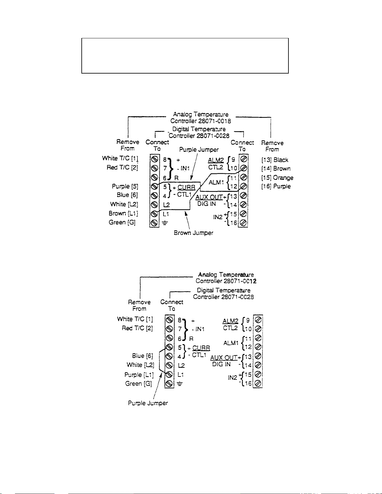
NOTE
When removing the 28071-QC27 Digital Temperature Controller (blue colored
unit) and replacing it with the 28071 -0028 Digital Temperature Controller (gray
colored unit), the electrical connections remain She same.
Figure 2 - Wiring Diagram Showing Electrical Connections (Refer to Table 1)
Figure 3 - Wiring Diagram Showing Electrical Connections (Refer to Tablet)
6
31E
Page 43
NOTE
When removing the 28071-0027 Digital Temperature Controller (blue colored
unit) and replacing it with the 28071 -0028 Digital Temperature Controller (gray
colored unit), the electrical connections remain the same.
Figure 4 - Wiring Diagram Show ing Electrical Connections (Refer to
Tab iel)
* Add ground wire (green) from terminal G to a
good ground connection in the control box.
Figure 5 -Wiring Diagram Showing Electrical Connections
(Refer to Table 1)
7
31F
Page 44
Timing Out From SET UP Mode
When in the SET UP Mode and no keys are pressed for a period o? 50 seconds, the controller times out
and reverts to the normal display (SET PT or TEMP).
Timing Out From Lower Display The normal display (SET PT or TEMP) is automatically shown if the DISP
key is not pressed for 60 seconds.
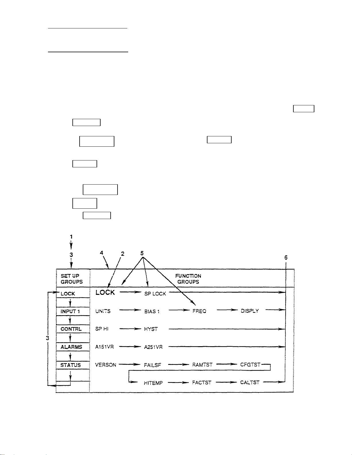
3. DISPLAYING And PROGRAMMING THE SET UP GROUPS
3.01 Displaying and Programming is the process of accessing the Set Up Groups, viewing/making selections
and returning to normal display. There are five Set Up Groups which can be accessed, they are: LOCK, INPUT
1, CONTRL, ALARMS, and STATUS Groups (see Figure 7). Follow the Steps:
1. Before changes can be made, enter the Set Up Mode by pressing the Lower Left Blank Key ( )
and the SET UP Key simultaneously.
2. Press the FUNCTION Key to display CONF LOCK. Press t Key to change display to show
NONE LOCK.
3. Press SETUP Key to sequentially move through the LOCK, INPUT 1, CONTRL, ALARMS and
STATUS Groups.
4. Press the FUNCTION Key to sequentially move through each Function Group.
5. Press t Key to change a selection or value within a Function Group.
6. Press the DISPLAY Key to return to normal display.
Figure 7 - Chart Showing Display Groups and Direction of Flow
12
31G
Page 45
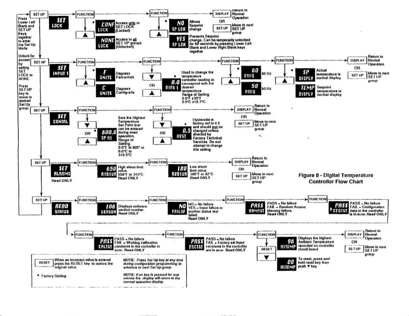
31H
Page 46

Diagnostic Error Messages
4.03 The controller runs background tests during normal operation. If a problem with the background ti
occurs, an error message is shown (flashing) in the Lower Display. In case of more than one
simultaneous malfunction, only the error message with the highest priority appears in the Lower Display, these
are called Diagnostic Error Messages (Table 3).
Table 3 - Diagnostic Error Messages
Corrective
Lower Display Action
EFAIL 1. Replace Controller
FAILSF 1. Turn Power OFF for 10 seconds,
1N1FL 1. Turn Power OFF for 10 seconds,
1N1RNG 1. Check Thermocouple and
then Turn Power ON.
2. If problem does not clear,
replace Controller.
then Turn Power ON.
2. If problem does not dear,
replace Controller.
Wiring (see Technical Manual).
2. if problem does not clesr,
replace Controller.
Controller Operation Problems
4.04 in addition to the error message displays, there are other symptoms which indicate that the controller is not
operating property. These problems can be identified by noting how the controller's displays, indicators,
and functions are reacting.
27
311
Page 47

A list of symptoms in Table 4 Troubleshooting Chart indicates controller failure or poor operation. Check the
indicator and display reactions and use the information contained in the troubleshooting chart during
troubleshooting.
CAUTION
Do not attempt to repair the controller as there are
no user replaceable parts Inside the unit.
When Corrective Action in Table 4 has been taken and the problem does not dear, then replace the Digital
Temperature Controller. When replacing the unit, be sure to follow the Installation and Programming Instructions.
Table 4 - Troubleshooting Chart
Symptom Cause Corrective Action
Upper Display: blank Power failure Check for Power
Lower Display: blank
Indicators: OFF
Controller Output: None
Upper Display: OK Relay Output Reconfigure
Lower Display: Displayed
Indicators: OK
Controller Output: Controller
Upper Display: OK Malfunction Check wiring on
Lower Display: OK in alarm terminals for
Indicators: OK output proper connection.
Controller Output: External
Upper Display: Display Incorrect Reconfigure to
Lower Display: OK
Indicators: OK
Controller Output: Relay
output
disagrees
with
controller
output
output
disagrees
with
displayed
output
alarm
function
does not
operate
properly
reading Power proper Power
unstable Frequency Frequency.
Chatter
28
controller.
Check wiring on
terminals,
especially jumper
for proper
connection.
31J
Page 48

Table 4 - Troubleshooting Chart (Continued)
Symptom Cause Corrective Action
Upper Display: FAIL RAM failure. Turn power OFF,
Lower Display: RAMTST
Upper Display: FAIL Configuration Step through the
Lower Display: CFGTST data in the STATUS tests
Upper Display: FAIL Factory set input Step through the
Lower Display: FACTST constants in the STATUS tests
Upper Display: (a value) Information To reset the tempera-
Lower Display: Display of only. ture reading, press and
maximum
ambient
temperature
controller is (RAMTST, CFGTST,
in error. CALTST, and FACTST)
controller in (RAMTST, CFGTST,
error. CALTST, and FACTST)
then ON to see if
error clears.
to allow the controller to
clear the problem, then
see if the problem clears
Check all displays for
programming accuracy.
to allow the controller to
clear the problem, then
see if the problem clears
hold the RESET Key.
then press the DOWN
ARROW Key.
31K
Page 49
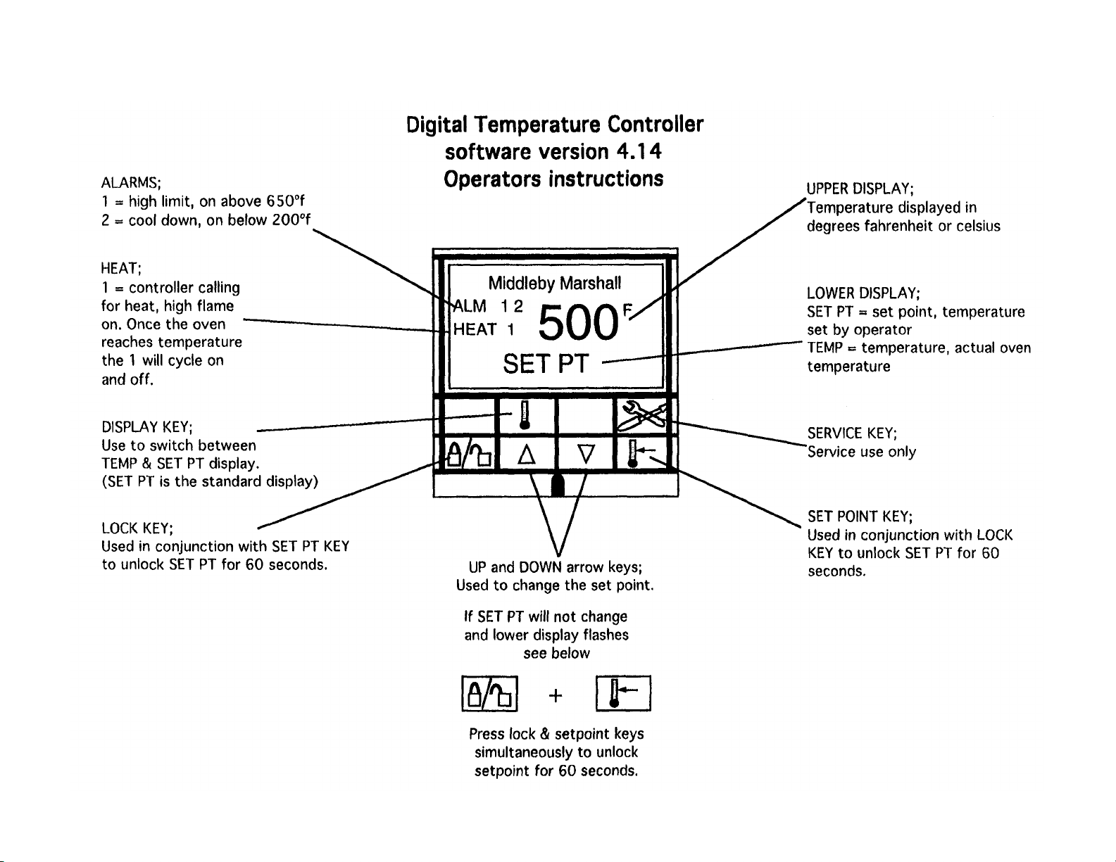
31L
Page 50
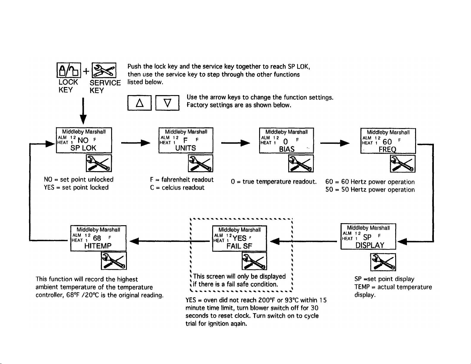
Digital Temperature Controller
software version 4.14
Servicers instructions
31M
Page 51

Bulletin No. MM-13 6
Date 9/28/93
Middieby Cooking Systems Group
1400 Toastmaster Drive • Elgin, Illinois 6012C
(708) 741-3300 • Sen/ice & Parts (708) 741-4406
Service Bulletin
SUBJECT: Digital Temperature Controller PN28071-0027 (Blue) or 28071-0028 (Gray) GENERAL
In some oven installations electrical noise/static have caused the Digital Temperature Controller not to
function property. Some common symptoms are:
1 . The Controller Display changes and/or may flash frequently.
2 . Temperature Set Point(s) may change without operator intervention.
3 . Gas solenoid valve opens and closes erratically.
The electrical noise/static enters the Digital Temperature Controller circuitry through the thermocouple wires.
The thermocouple wires are attached to terminals 7 and 8 on the rear of the controller. To correct this problem,
the supplied Filter Capacitor Assembly (PN 27170-0283) should be connected from terminals 7 and 8 to Ground
(G).
APPLICATION
Model PS200 Series, Model PS250, Model PS300 Series, and Model PS500 Series.
COMPATIBILITY
The Filter Capacitor Assembly is installed on the rear terminal strip of either Digital Temperature
Controller PN28071-0027 (Blue) or 28071-0028 (Gray).
FEATURES
• Filters electrical noise/static.
AVAILABILITY
• Effective September 20, 1993 part orders for the Digital Temperature Controller
include the Filter Capacitor Assembly installed on rear of unit.
31N
Page 52
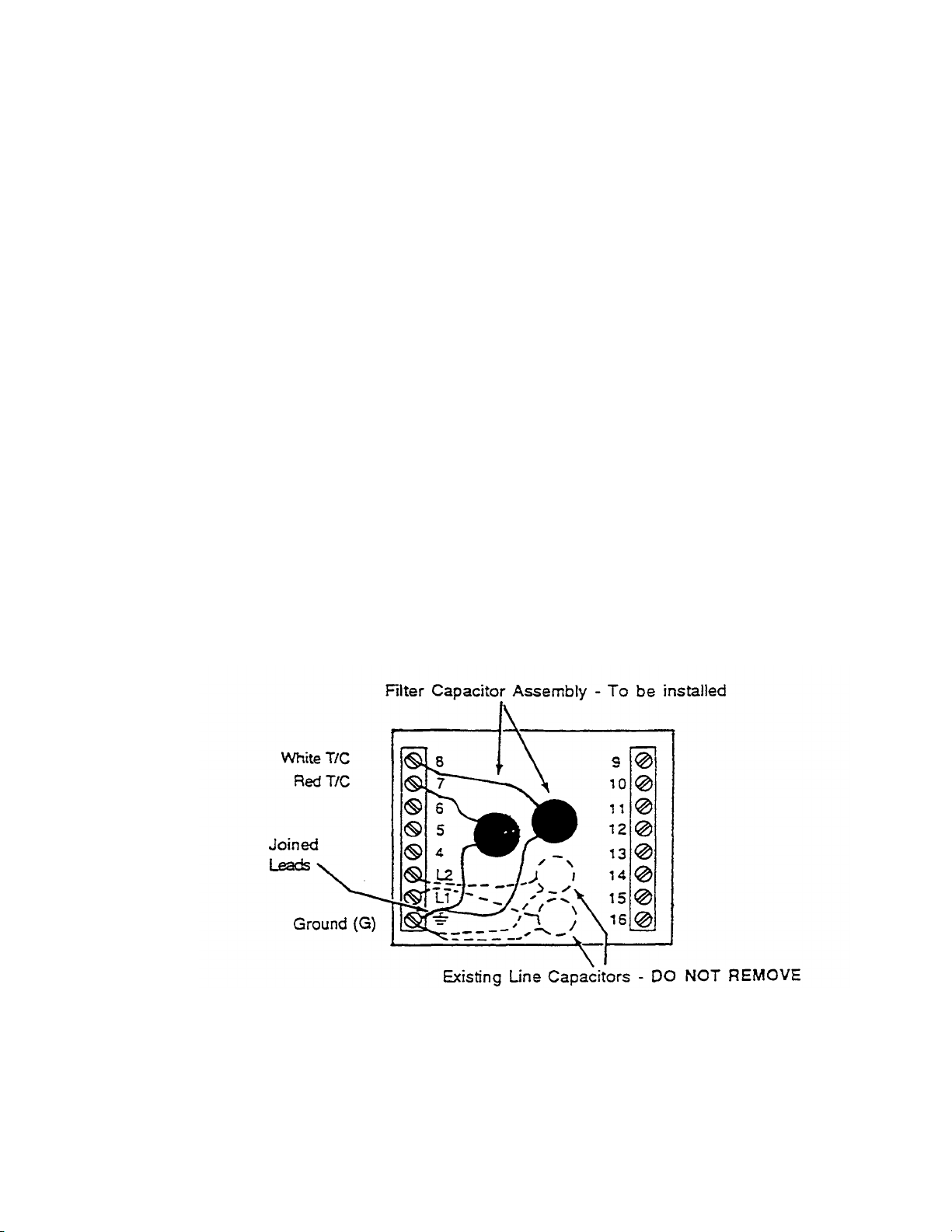
• Effective September 20. 1993 ovens shipped with the Digital Temperature Controller include
the Filter Capacitor assembly (installed).
• Effective October 1, 1993 Middleby Marshall will fill all Orders for the Filter Capacitor
Assembly.
DISPOSITION OF INVENTORY
All distributor inventory should be upgraded with the filter capacitor assembly.
INSTALLATION PROCEDURES
To Install the Filter Capacitor Assembly (PN 27170-0283), proceed as follows:
1 . Turn "OFF* all power to the oven.
2 . Open the Control Compartment
3 . Install the filter capacitor assembly on the terminals. Refer to Figure 1. The capacitors should
be mounted across the back of the controller.
a. The joined leads of the two capacitor assembly are connec ted to Ground (G).
b. Ether single capacitor lead is connected to Terminal 7, and the other single
capacitor lead is connected to Terminal 8.
4 . Close the Control Compartment.
5 . Turn Oven "ON", check and/or set the set point(s), monitor for stable
display(s) and operation. Refer to appropriate documentation covering the Digital
Temperature Controlfer.
Figure 1 - Rear View of Digital Temperature Controller Showing the Filter Capacitor
Assembly Connected to the Terminals
310
Page 53
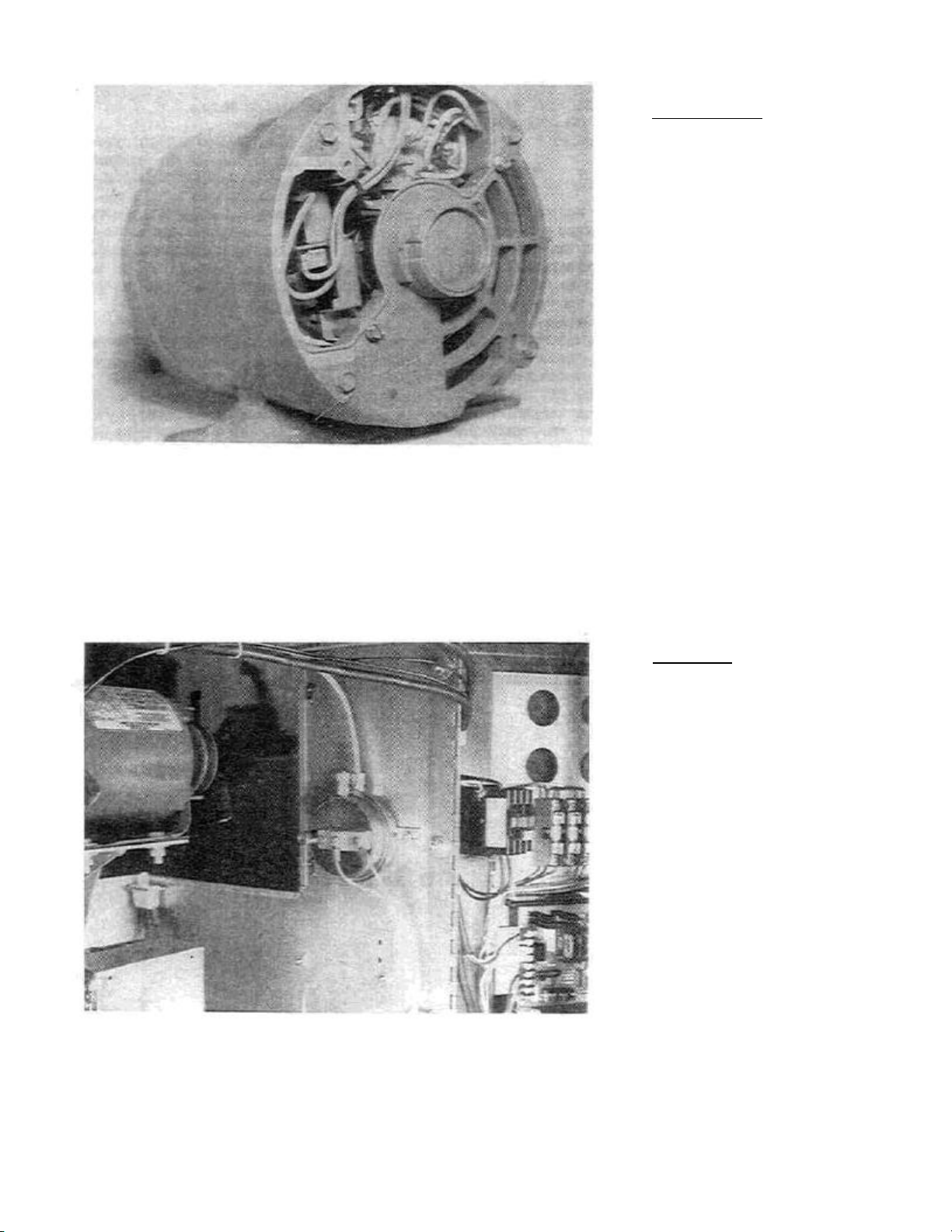
Figure
39.
PS31
0/360
Motor Centrifugal Switch on Rear
of Motor (MM P/N 27170-0144)
III. MOTOR CENTRIFUGAL
SECTION 2 SERVICING
COMPONENTS
SAFETY SWITCH
PS310/360 ONLY
(See Figure 39)
A normally closed limit switch is
mounted inside each blower motor.
When the motor is not running the
centrifugal switch weight holds the
switch open. As the motor reaches
full RPM the weight moves away
from the switch permitting the switch
contacts to close. These switches
are located in the rear of the motors.
When the switch contacts of both
blower motors are closed it permits a
circuit to go from the heat switch to
the high limit switch. If a blower
motor is not operating the switch will
not close and the oven will not light.
There is no adjustment that can be
made to the switch.
If the switch is operating properly
both sides of the brown wires coming
from the switch should be hot when
the motor reaches full RPM.
Removing the rear motor wiring
cover plates allows access to the
centrifugal switch. The switch may
be replaced when faulty with MM
P/N 27170-0144. Refer to Figure 39.
IV. AIR PRESSURE SWITCH
PS200 ONLY
(See Figure 40)
A normally open micro-switch is
mounted inside the Air Pressure
Switch Assembly. When the blower
fan is not operating no air pressure is
applied to an air tube end located in
front of the fan blades so the Air
Pressure Switch remains open.
When the blower fan is up to speed
pressure is applied to the air switch
diaphragm which in turn closes the
micro-switch contacts completing the
heating circuit.
Figure 40. PS200 Air Pressure Switch
37
Page 54

SECTION 2 SERVICING
V.
GAS BURNER AND TRAIN
COMPONENTS
B. Intermittent Ignition Device
NOTE: The PS200/PS310/PS360 all use the identical burner, burner
controls and high flame valve. The only difference is the main burner
orifice.
A. Sequence of Operation
When all safeties are satisfied, turning the heat
switch ON will supply 110 volts directly to the burner
control circuit. The 110 volts is applied to the primary
side of the transformer and converted to 24 Vac. The
transformer sends 24 Vac to the time delay relay coil.
On a cold start, the relay will not energize for 15-30
seconds. When the relay energizes it closes and
completes a 110 volt circuit to the burner blower
motor. The motor starts and when it comes up to
speed the centrifugal switch on the motor is closed
and the 24 volt circuit through it is completed to the
control board mounted on the left side of the
machinery compartment. The control board will
energize the pilot valve, allowing pilot gas to flow. At
the same time, the control board ignites the spark to
light the pilot. When the pilot flame is established the
safety circuit is completed and the control board
opens the main gas valve and ignites the burner. If
the oven is calling for heat the temperature controller
will energize (open) the high flame solenoid. When
the temperature controller is satisfied it opens the
circuit to the high flame solenoid valve. This closes
the valve and puts the burner on low or "by -pass"
flame. This sequence will continue until the "heat"
switch is turned to the OFF position, opening the 110
volt circuit to the control board, permitting both the
pilot and main valves to close.
All Pacesetter PS200/PS310/PS360 gas ovens are
equipped with an intermittent ignition device (1ID)
type automatic ignition pilot burner assembly. The II
D creates a spark to light the pilot and a flame probe
must prove that the pilot is lit before the main gas
valve can become energized and cycle the burner
on. An ignitor sensor probe surrounded by pilot
flame will permit the main burner valve to energize.
The control system includes proof of burner blower
rotation.
The burner control system incorporates prepurge on
cold start, proof of burner blower rotation, pilot
ignition and proof of pilot flame. A flame sensor
probe is surrounded by the pilot flame. If pilot flame
is lost the control unit will automatically try to relight
the pilot for 90 seconds. If ignition does not occur
the control will then "lockout" the pilot. To relight the
pilot the "heat" switch must be momentarily turned
OFF for 60 seconds and then moved to the ON
position.
38
Page 55
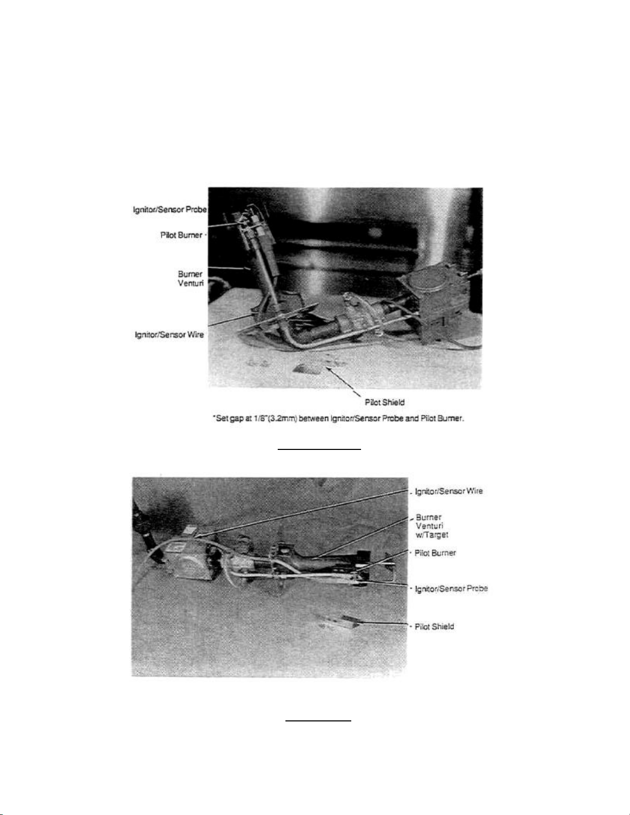
C. Gas Burner Components
1. Burner 110 Volt Power Supply - The burner main
power supply is connected to terminals L1 and L2
located in the electrical junction box to the right side of
the burner.
2. Pilot Burner Assembly (IID) is attached to the
main burner and consists of a flame sensor ignitor
electrode, a pilot shield and the pilot burner. The spark
ignites the pilot and a circuit is completed from the
flame sensor probe through the flame to the pilot
SECTION 2 SERVICING
COMPONENTS
burner. This safety circuit must be completed before
the main burner will light.
The ignitor sensor probe located on the pilot assembly
is used to prove the presence of the pilot flame. An
electrical current is sent to the probe and if a pilot
flame is surrounding the pilot burner and the probe at
the same time, the current is then conducted through
the flame to the pilot burner which is grounded. This
completes the safety circuit and allows the main burner
to light.
MODELS PS310/360
•Set gap at 1 /8"(3.2mm) between Ignitor/Sensor Probe and Pilot Burner.
MODEL PS200
Figure 41. Pilot Shield Removed from Burner.
39
Page 56
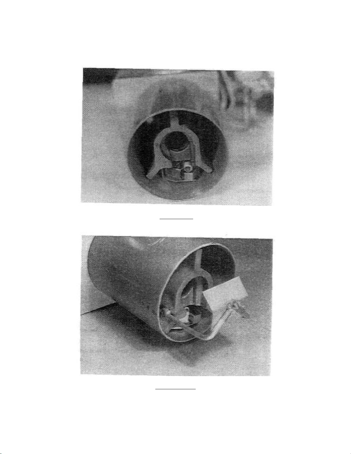
SECTION 2 SERVICING
COMPONENTS
Pilot Shield
The pilot shield located on the bottom of pilot is used to
prevent drafts, etc. from blowing the pilot flame away
from the sensing probe.
Burner Flame Target
The burner venturi flame target is installed on all
Model PS310/360's after 6/87. It is also installed on all
PS360S, PS360Q and all PS200. The target aids in
distributing the flame in the burner chamber.
PILOT SHIELD
Front of Burner With Pilot Shield Installed
FLAME TARGET
(Installed on PS310/360 after 6/87. Installed
on all PS360S, PS360Q and all PS200.
Figure 42. Pilot Shield and Burner Flame Target.
40
Page 57
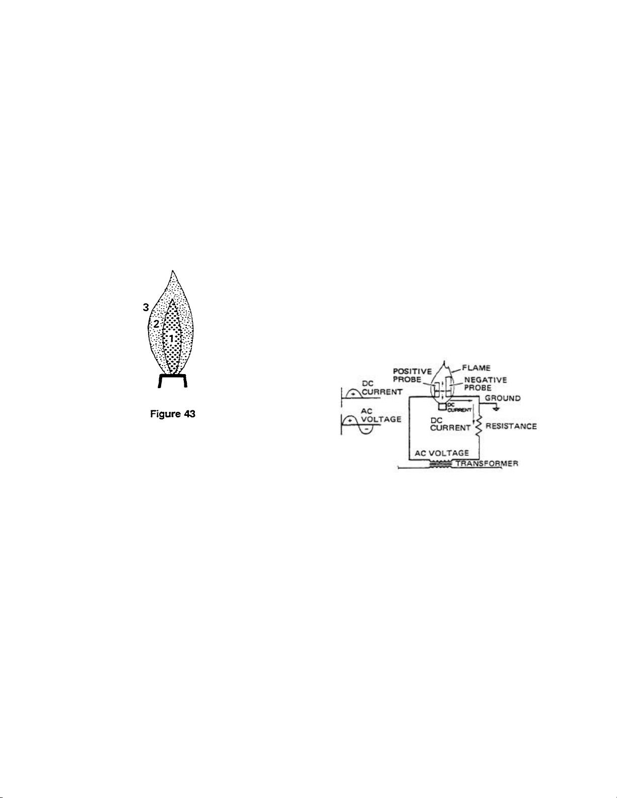
Pilot and Proof of Pilot Flame Rectification
An inner cone that will not bum because excess fuel is
Detailed Explanation.
Sensing Methods
With standing pilots, heat is a necessary ingredient
for proper thermocouple operation. But this is not the
case with II DS when flame conduction or rectification
is used. To better understand the principles of flame
conduction and rectification, we must first understand
the structure of a gas flame (See Figure 43).
With the proper air-gas ratio to give a blue pilot flame,
three zones exist.
SECTION 2 SERVICING
COMPONENTS
Flame Rectification
With flame rectification, the flame and probes are used
in a similar manner. There is one important difference.
The area of one probe that is exposed to the flame
must be greater than area of the other probe that is
exposed to the flame.
In Figure 44 the flame is again used to conduct an AC
signal. Both probes are in contact with the flame. The
probe with the largest surface area attracts more free
electrons and, as a result, becomes the negative
probe. Therefore, the direction for the conduction of
current through the flame is from the positive probe to
the negative probe. Note also that the AC voltage sine
wave has not changed, but the negative portion of the
current sine wave has been chopped off. This positive
portion now represents a DC current. This is the
phenomenon of flame rectification.
Zone1
present.
Zone 2
Around the inner, fuel rich cone is a blue envelope. In
this area is a mixture of vapor from the fuel rich inner
cone and the secondary, or surrounding, air. This is
where combustion occurs.
Zone 3
Outside the blue envelope is a third zone that contains
an excessive quantity of air.
Of concern is the second, or combustion area. This is
where the burning occurs and is the area that is of prime
importance for good flame sensor location.
Figure 44. Flame Rectification.
41
Page 58
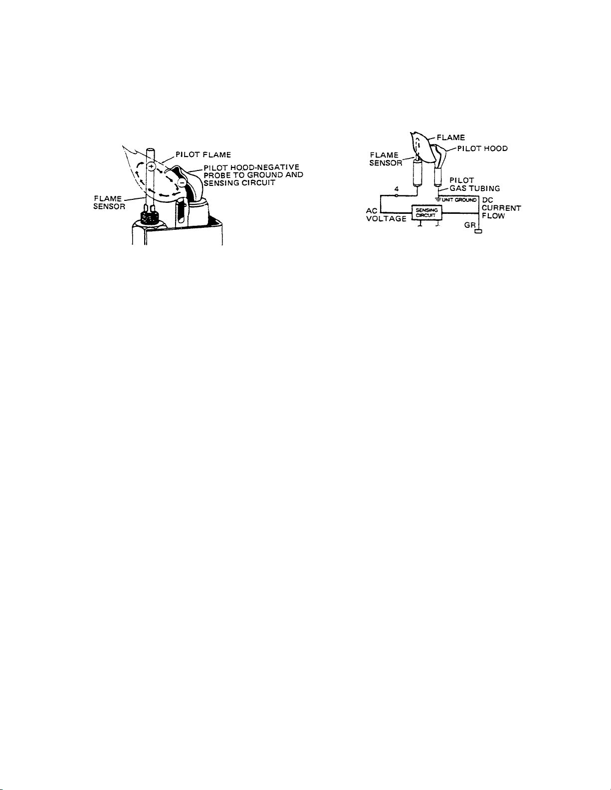
SECTION 2 SERVICING
COMPONENTS
Figure 45. Flame Rectification Pilot
To apply this principle to an IID, a pilot and flame
sensor have been substituted for the two probes (See
Figure 45). After the pilot is ignited, a DC current flow
of 1.5 micro-amps or more is conducted through the
flame, from the flame sensor, (the positive probe) to
the pilot tip, (the negative probe). The pilot tip, acting
as the negative probe, completes the circuit to
ground. The II D sensing circuit uses this DC current
flow to energize a relay and open the main burner
gas valve.
THE FOLLOWING CONDITIONS WILL HAVE A DIRECT
BEARING ON EVERY IID APPLICATION:
And Probe
Maximum inlet pressure for natural gas applications
should be limited to 10.5" W.C. On LP applications, the
inlet pressure should be limited to a maximum of 14W.C.
Outlet gas pressure must be 3.5" natural gas, 10.5"
L.P. gas. These pressures are measured when the
oven is in the LOW flame mode.
Temperature
Ignition controls should not be exposed to temperatures
exceeding 140° F (60° C) or less than-40°F(-40°C)
Voltage
The supply voltage to the ignition controls should be
within the following ranges:
120 VAC controls -102 to 132 VAC
24 VAC controls - 21 to 25.5 VAC
24VAC systems should use transformers that will
provide adequate power under maximum load
conditions.
Gas Pressure
The inlet gas pressure should be a minimum of 1"
W.C. above the manufacturer's recommended
manifold pressure. Under no condition, should the
inlet gas pressure be below the manufacturer's
recommended minimum inlet pressure
Pilot Application
The pilot and flame sensor application is the most
critical aspect of the IID application.
The pilot flame must make contact with the pilot tip and
surround the flame sensor probe. A microammeter is
necessary to verify that the proper amount of current is
being maintained through the pilot flame. On the control
board, the minimum value required is 1.5 microamps. If
the minimum signal is not being maintained at all times,
rapid short cycling of the main burner or "no main
burner on" conditions can exist. Rectification based
ignition systems respond in less than 0.8 of a second to
a loss of flame. Any deflection of the pilot flame away
from the flame sensor, or pilot tip, could result in rapid
cycling (chattering) of the main burner gas valve, or
prevent the main burner from coming on.
42
Page 59

Service Bulletin
NO. 128
Date 7/22/91
A MIDDLEBY COMPAHY
SUBJECT: Burner Pilot/Ignitor Assembly P/H 27363-0001
Replaced by P/N 42810-0117 (Kit)
The burner pilot/ignitor assembly, P/N 27363-0001 has been discontinued and replaced by
P/N 42810-0117 Pilot/Ignitor Kit. The kit contents are:
Qty. Part Number Description
1 27363-0002 Pilot/lgnitor
1 27170-0264 Pilot/lgnitor Bracket
1 88210-0067 Pilot/lgnitor Replacement
Instructions
The new assembly must mount approximately 1/4 of an inch further forward from the
end of the burner venturi to assure proper pilot operation and burner ignition.
Therefore, the new mounting bracket is supplied with each pilot/ignitor and mus^ be
installed when replacing an old pilot/ignitor. Be careful to note that the hole
locations are the only difference between the old and new brackets. The difference
in the pilot/ignitor assembly is more obvious. Refer to instructions attached for
further details. Note that the four ^10-32 screws and existing pilot shield are to
be reused.
This change is effective on all PS-200 series ovens, all PS-300 series ovens, all
PS-350 ovens with the Honeywell gas valve conversions (Kit#428l0-0082) and anywhere
P/N 27363-0001 is used.
James E. Urani
Field Technical Engineer
JEU:aa
(over)
8300 Austin Avenue • Morton Grove, Illinois 60053
(708) 966-8300 • FAX (708) 966-8701
42A
Page 60
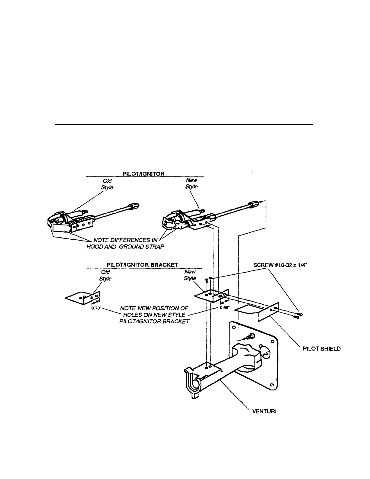
ITEM QTY M
MP/N
DESCRIPTION
1 1 27363
-
0002 PILOT IGN1TOR
1
KIT CONTENTS:
PILOT/IGNITOR REPLACEMENT INSTRUCTIONS
USING KIT #42810-0117
IMPORTANT: When using Kit #42810-0117 the old style pilot/ignitor
bracket must be replaced with the new style bracket contained in the
kit or the burner will not light.
2
3 1 88210-0067 PILOT/IGNITOR REPLACEMENT INSTRUCTIONS
27170-0264
PILOT IGNITOR BRACKET
MM P/N 88210-0067
P7/91
Page 61
Middleby Cooking Systems Group
1400 Toastmaster Drive • Elgin, Illinois 60120 (708) 7413300 • Service & Parts (708) 741-4406
SUBJECT: Pilot Line Tee Kit (PN 30185)
Bulletin No. MM-1 37
Date 03/21/94
GENERAL:
The Pilot Outage Situation
In the past all Middleby Marshall conveyor ovens were equipped with a combination gas valve with a spring
loaded on/off knob which was tan in color. We found that when this tan knob material was exposed to heat it
was more vulnerable to attack by air born animal proteins. The combination of heat and grease caused the
knob to crack. Once the knob was cracked the spring would force it to the closed position thereby shutting
down the oven. To correct this problem we changed to a different combination gas valve with a knob made
of a glass fiber filled nylon compound that is blue in color. As time went on we noticed an increase in pilot
problems. For example:
1. Pilot blows out causing constant re-ignition.
2. Constant re-ignition creates electrical noise which causes the temperature control and/or the
conveyor control to function erratically.
3. Raw gas odor as it escapes into the oven when the pilot blows out but the second stage of the
valve has not yet closed.
4. Soot build up on the pilot of propane applications.
Both your technicians and our technical staff dealt with each of these cases by adjusting pilot hoods,
adjusting pilot shields and changing pilot orifice sizes and low flame orifice sizes. All of these fixes worked on
a case by case basis and therefore clouded the true cause. Further investigation has shown that the blue
knob combination gas valve design does not regulate at the low end of the BTU range as effectively as the
old valve. As the oven goes into low flame the
1
42C
Page 62

servo bounces up and down as it hunts for the proper level. This can be seen on a water column gauge
connected to the output side of the vaive. This bouncing line pressure causes pressure surges in the pilot
line too. These surges lift the pilot oft the sensor probe causing the problems described above. We have
found that a properly regulated pilot line will smooth out the surges and create a strong piiot not effected by
the vaive operation.
Correcting The Pilot Outage Situation
in order to regulate the piiot properly all ovens leaving the factory after February 24, 1994 are equipped with
a pressure tap in the pilot line. This tap is a basic line tee with a plug. The technician can tap into the pilot
line with a water column gauge from this tee and adjust the pilot pressure using the pilot adjustment screw
on the combination gas valve. We will set them at the factory but since all installations are unique we will
also ask the instalier to check/adjust the pressure on the installation check out sheet.
As we worked with our combination gas valve supplier on this project we were surprised to learn of another
factor clouding the issue. We were told that some combination gas valves were shipped to us with burrs in
the pilot adjustment portal. The piiot of these valves is difficult to adjust unless you break through the burr. If
the water column gauge does not register any change after the adjustment screw has been turned ail the
way down, then the technician must apply more torque to break through the burr, back the screw out until
the top of the screw is flush with the top of the access hole, and turn the screw down again. This must be
repeated several times. This is not a typical procedure and must be kept in mind.
Customers With Known Existing Problems
Middleby Marshall is doing all it can to assure future customers worry free operation with minimal down
time. But the customer who has already purchased our ovens may be having difficulty and he doesn't even
know it. Or perhaps one of your technicians is wrestling with an oven problem which may be related to this
pilot situation. Either way, this is where we need your help- In a few days we will send you a number of pilot
tee kits as described below. We will bill you as if it were a standard parts purchase- If you know a customer
who is having some of the problems described above, install the kit, adjust his pilot pressure and if
necessary, replace the combination gas valve according to the instructions provided- Use the parameters
set in the APPLICATION section of this bulletin to determine candidates and billing procedures.
All Other Customers
In addition, we want to take care of any potential problems by having the kits installed, the pilot pressure
adjusted and if necessary, the combination gas valve replaced whenever a technician is already on sight for
another call. In other words, if a service call is requested for unrelated issues and the oven has a blue knob
combination valve then we would like your technician to follow the directions supplied with the pilot tee kit
(PN 30185) as long as he is there. Again refer to the APPLICATION section for details.
Your assistance in making this program work will reinforce the Middleby Marshall/Authorized Service Agent
teamwork concept of surpassing our mutual customers expectations- This is an
2
42D
Page 63

opportunity for you to display a preventive strategy to your customers and come out the hero. it also gives
you an opportunity to promote the value of using factory trained Authorized Service Representatives who
use only Genuine Factory Authorized Parts.
The Pilot Line Tee Kit (PN 30185) includes:
Quantity Part Number Description
1 30001 Branch Tee
1 30002 Branch Tee Plug
1 30184 Instructions
Tools Required:
Middleby Marshall Technical Manual (PN 88210-0019)
DC micro-amp meter
Water Column Gauge (do not use a dial meter type)
Aluminum Tube Cutter
Soap Solution For Gas Leak Test
Other Standard Tools Of The Trade (open end wrench set, screw driver set, etc.)
APPLICATION:
All PS-200, PS-300, and PS-500 series ovens equipped with the blue colored knob combination gas valve.
Customers With Known Existing Problems:
If you know a customer who is having some of the problems described above, call the Middieby Marshall
Service Manager for authorization to make a special trip to install the kit and adjust the pilot pressure. If
the combination gas valve will not adjust properly even after breaking through the burr, then also change
the valve. Return the combination gas valve to Middleby Marshall along with your invoice. Invoice Middieby
Marshall using standard warranty procedures. Middleby Marshall will issue credit for travel, mileage, labor,
and parts as long as the invoice has an authorization code.
All Other Customers
Whenever a technician is already on sight for another call and the oven is equipped with a blue colored
knob combination gas valve then he is to install the kit and adjust the pilot as long as he is there. If the
existing combination gas valve will not adjust properly even after breaking through the burr, then also
change the valve. Return the combination gas valve to Middleby Marshall along with your invoice. Invoice
Middleby Marshall using standard warranty
3
42E
Page 64

procedures. Middleby Marshall will issue credit for pans and the portion of the labor time related to the kit
installation, valve installation, and pilot pressure adjustment.
Middleby Marshall expects the Pilot Tee Kit (PN 30185) and the Combination Gas Valve Kit (PN 42810-0121) to
be mandatory truck stock- Therefore, we will not pay for second trips.
COMPATIBILITY:
The Pilot Line Tee Kit (PN 30185) is compatible with all Middieby Marshall conveyor ovens equipped with the
blue colored knob combination gas valve.
The pilot line tee is already installed on all ovens shipped after February 24, 1994.
FEATURES:
- Eliminates pilot fiame outages
- Fits all Middleby Marshal! pilot lines
- Allows technician to monitor pilot line pressure
AVAILABILITY:
Effective M arch 21, 1994 Middleby Marshall will fill all orders for the Pilot Line Tee Kit (PN 30185).
DISPOSITION OF INVENTORY:
No prior inventory exists before March 21, 1994. The Pilot Line Tee Kit (PN 30185) is a mandatory truck and
warehouse stocking item.
The Combination Gas Valve Kit (PN 42810-0121) is a mandatory truck and warehouse stocking item.
4
42F
Page 65

Branch Tee
P/N 30001
INSTALLATION INSTRUCTIONS
PILOT TEE ON PACESETTER
OVENS
KITP/N30185
Kit Contains:
Branch Plug P/N 30002
Installation Instructions P/N 30184
Tools Required:
Middleby Marshall Technical Manual (PN 88210-0019)
DC Micro-amp Meter
Water Column Gauge (do not use a dial type meter)
Aluminum Tube Cutter
Soap Solution For Gas Leak Test
Standard Tools of the Trade (open end wrench set, screw driver set, etc.)
Middleby Marshall Inc. • 1400 Toastmaster Drive • Elgin, IL 60120 • (708) 741-3300 • FAX (708)741-4406
Middleby Corporation Service Hotline 1-800-238-8444
©1994 Middleby Marshall Inc.
Part# 30184
P3/94
42G
Page 66

INSTALLATION INSTRUCTION
PILOT TEE
K1TP/N30185
A. INSTALLATION OF TEE AND PLUG KIT P/N 30185
IMPORTANT: BEFORE ATTEMPTING TO INSTALL THIS KIT, READ THESE INSTRUCTIONS THOROUGHLY. TURN
OFF GAS AND MAIN POWER TO OVEN BEFORE INSTALLING THIS KIT.
1. Remove pilot line tubing from between the combination gas valve and the burner plate. Refer to Figure 1.
2. Cut the tubing for installation of the tee as shown in Figure 1. Cut a 3/4" piece out of the pilot line tubing to
insert the tee as shown in Figure 1. NOTE: The tubing will insert 1/4" into the tee at both ends.
3. Replace the pilot tube and tee and tighten all connections. Check that there are no kinks in the pilot line.
4. Fire the oven and check all connections for gas leaks by painting them with a rich soap and water solution.
Bubbles indicate a gas leak.
5. If a gas leak is detected, tighten the pipe connection and recheck for leaks. Replace the part(s) if gas leak
cannot be stopped.
B. PILOT PRESSURE REGULATION - Using Combination Gas Valve Pilot Adjustment
1. Unscrew the plug from the pilot tee and install a water column gauge. To avoid calibration problems do not
use a dial face mechanical W.C. gauge. Refer to Figure 1, PS300 Lower Oven for an example of water gauge
connection.
2. Wait until oven is running on low flame in order to adjust pilot pressure. Turn the temperature control set point
down well below the actual temperature in the oven to maintain low flame.
3. Gain access to the pilot adjustment screw under the screw on combination gas valve as shown in Figure 1.
4. Read the water column gauge connected at the tee while turning the pilot screw adjustment. Turning clockwise decreases pressure and turning counterclockwise increases pressure.
NOTE: Some combination gas valves may have burrs in the pilot adjustment portal. The pilot of these valves ii
difficult to adjust unless you break through the burr. If the water column gauge does not register any change
after the adjustment screw has been turned all the way down, then apply more torque to break through the
burr, back the screw out until the top of the screw is flush with the top of the access hole, and turn the screw
down again. This must be repeated several times.
Adjust the pilot line pressure as follows:
If oven is running on NATURAL GAS adjust pilot pressure to 3.5" - 4.0" WC. If
oven is running on PROPANE GAS adjust pilot pressure to 8.0" -10.0" WC.
5. Replace screw over pilot adjustment screw.
42H
Page 67
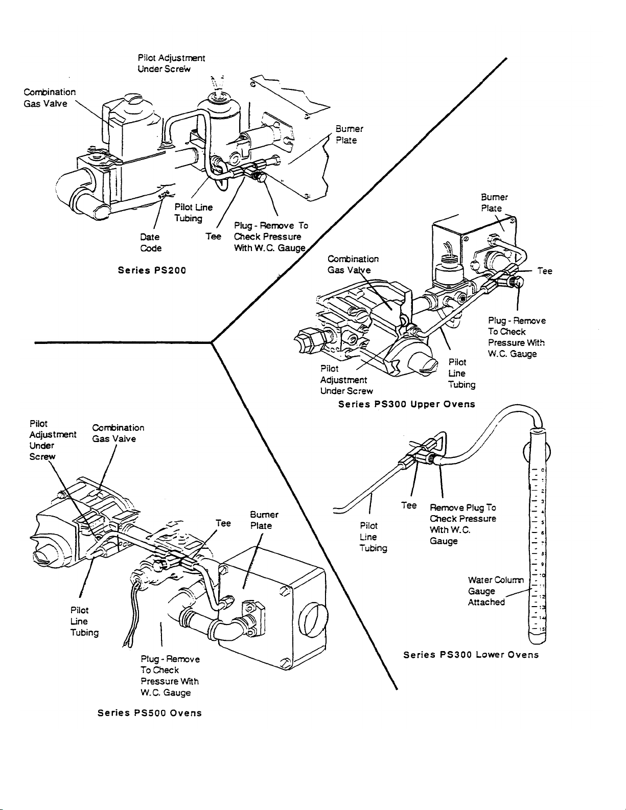
Figure 1
42I
Page 68

C. PILOT LIGHT CHECK
1. Cycle oven back onto high flame and check burner flame for proper color. Natural gas appears soft blue with
orange tips and propane gas appears orange. The shutter plate on the burner blower motor is typically set at:
PS200 Series =1/16" to 3/32"
PS300 Series = 1/8" to 3/16"
PS500 Series = 1/8" to 1/4"
Each installation can vary. Adjust the shutter plate until the flame color is correct. Also check for proper
microamp readings. Refer to Technical Manual (P/N 88210-0019), Section 2.
2. Turn burner off by cycling the burner heat switch momentarily two or three times to check for proper reignition. If
difficult lighting or burner outage occurs, go to Step 3. If reignition is satisfactory then skip to Step 4.
3. If burner is difficult to light or goes out intermittently, check for proper microamp adjustment of pilot using
Technical Manual (P/N 88210-0019), Section 2. Recheck pilot pressure on low flame to be sure it is adjusted
within the correct parameters listed in Step B-4 of these ins tructions.
4. Turn off the gas flow to burner by turning heat switch to the OFF position.
5. Remove water column gauge and install tee plug and check for leaks.
For further assistance with any portion of these instructions call the
Technical Service Hotline at 1-800-238-8444.
42J
4
Page 69
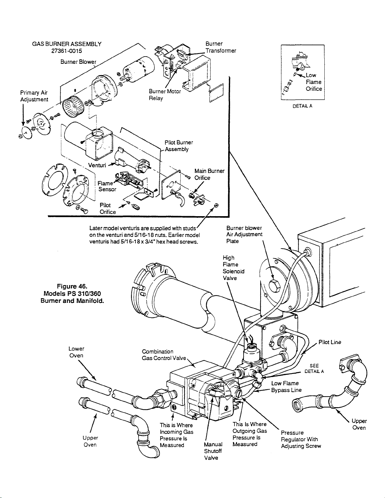
SECTION 2 SERVICING
COMPONENTS
43
Page 70
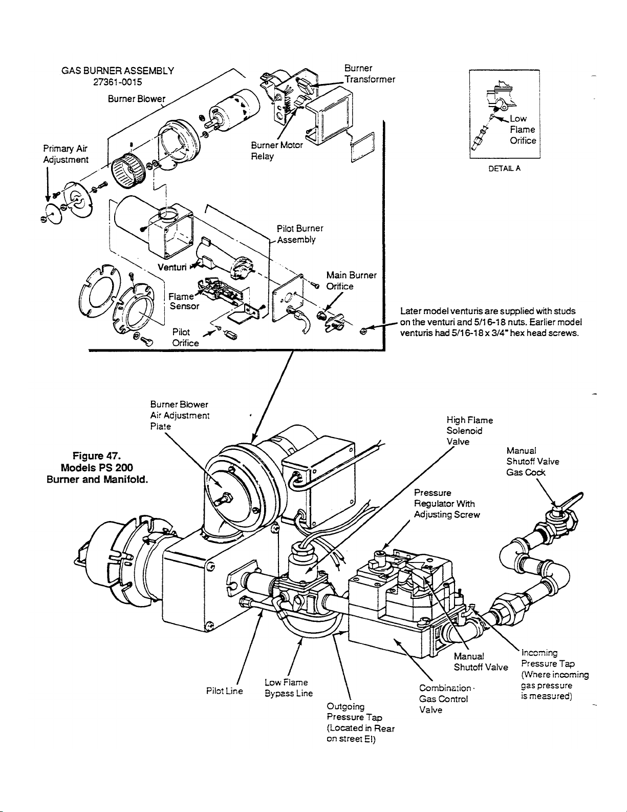
SECTION 2 SERVICING
COMPONENTS
44
Page 71

Other conditions that can cause the failure of the
main burner to come on or rapid chattering of the
main burner are:
1. pilot flame is too small or,
2. gas pressure is too low for proper pilot flame
impingement on the flame sensor.
SECTION 2 SERVICING
COMPONENTS
applied to the coil of the relay, the contacts will dose
and permit 110 volts to go to the burner blower motor.
This 15-30 second delay is a prepurge for a cold start.
When the coil of the relay is warm, this delay is
bypassed.
D. Burner Troubleshooting
In these cases, the pilot may ignite, but the main
burner gas valve will not be energized. It is also
impossible for drafts or unusual air currents to deflect
the pilot flame away from the flame sensor. Deflection
of the pilot flame may also be caused by main burner
ignition concussion or roll out of the main burner
flame.
An additional point to be considered is the condition
of the pilot flame. If the pilot flame is hard and
blowing, the grounding area of the pilot is reduced to
a point where the necessary current is not being
maintained, and a shut down of the system will result.
The positioning of the flame sensor is also critical in
the pilot application. Positioning of the flame sensor
should be such that it will be in contact with the
second, or combustion area of the pilot flame.
Passing the flame sensor through the inner cone of
the pilot flame is not a recommended procedure. For
this reason, a short flame sensor may provide a
superior signal over a longer one. The final
determination of the sensor location (length) is best
determined by the use of a microammeter.
3. Burner Blower Motor is located on the right side of
the burner housing and is used to supply primary air
for combustion. This motor drives a squirrel cage
blower wheel located in the main housing of the
burner. The motor requires no lubrication. The motor
is a 110 volt motor and has an internal centrifugal
switch that controls the 24 volt power to the gas
valve. Failure of the motor will result in the burner not
lighting.
4. Primary Air Adjustment located on the left side of
the burner is a round silver colored plate that is held
in place by a 1/4" nut on a threaded rod. By turning
this plate either counterclockwise for more air or
clockwise for less air you can control the microamp
reading of the safety circuit.
5. Burner Transformer is located in the electrical
junction box on the burner. The purpose of the
transformer is to supply 24 volts to the burner motor
relay and also to the 24 volt gas valve through the
centrifugal switch located in the burner motor.
The following is a preliminary troubleshooting
procedure. Refer to "Burner Test Equipment and
Usage" for a more complete troubleshooting
procedure.
1. Power Supply - connect a voltmeter across L1 and
L2 in control box, you should get 110-115 volts.
2. Relay a. Connect voltmeter from terminal 3 on relay to L2
on terminal board - reading should be 110 to 115 volts.
b. Connect voltmeter across the low voltage
terminals on relay - reading should be 24V. If you do
not get a 24V reading, the transformer should be
replaced.
c. If 24V is present at the relay and if after 15 to 45
seconds you do not get 110V on terminal 3 of the relay
- replace the relay.
3. Burner Blower Motor - If there is 110V to terminal 3
the motor should be running. If the motor is not running
-replace the motor.
4. Burner Blower Motor Centrifugal Switch - If the motor
is running at top speed and you do not have 24 volts at
the burner control board, then the centrifugal switch is
either loose or defective. The switch must then be
tightened or replace the motor.
5. Main Gas Valve and Control Board -Once 24V is
supplied to the control board you should have 24V
between terminals PV and MV/PV on the control
module.
If you have a 24V reading the pilot valve should be
open and the spark should be on to ignite the pilot gas.
When the pilot gas has ignited, the main burner should
come on. If not, check MV terminal to ground and see if
24 volts is present. If no voltage is present replace the
electronic board. It is possible to have a pilot on but
you can hear the spark continue to try to light the pilot.
If this continues for more than 30 seconds, then it
should be assumed that the flame sensor is not
working properly. This may be easily checked. Refer to
Section on Control Module Flame Sensor Test.
6. Burner Motor Relay located in the electrical
junction box on the right side of the burner is a 24 volt
time delay relay. Approximately 25 seconds after
power is
45
Page 72
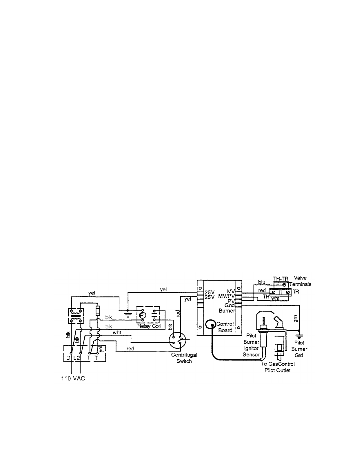
SECTION
2
SERVICING
COMPONENTS
A reading of 1.5 microamps or greater should be
obtained. If a poor reading is obtained, pilot flame and
sensor are probably not making good contact. This will
keep the main valve from opening. Refer to the section
on flame rectification. If the microamp reading is good
and 24 volts cannot be obtained at terminal MV then
the electronic board must be replaced.
E. Burner Ignition System -- Start-Up and
Checkout.
bb. Spark cuts off when pilot flame is established.
cc. Main gas valve opens and main burner lights
after gas reaches the burner ports.
NOTE: Main burener flame may not be satisfactory until
the gas input and combustion air have been adjusted.
2. Check Grounding.
A common ground is required for the pilot burner, the
ignitor/sensor, the GND terminal of the control board,
and the main burner. The main burner generally serves
as the common ground.
The only piece of test equipment needed to check the
burner system on the PS 200, 310/314/360 is a volt
AMP/OHM meter which will read Micro amps (uA).
1. Burner Operation - the basic burner operation is as
follows:
a. Shut off manual gas valve for oven. Turn the
Burner and Heat switches ON. The spark should begin
at the pilot burner within 30 seconds. Since no gas is
present the spark will continue for the lockout timing
period of 90 seconds.
b. Turn the Heat switch OFF then turn on gas
supply. Set the temperature controller set point above
actual oven temperature.
c. Turn the Heat switch ON. The system should
start as folbws:
aa. Spark turns on and pilot gas valve opens at
once. Pilot burner ignites after gas reaches the pilot
burner.
If the ground is poor or erratic, safety shutdowns may
occur occasionally even though operation is normal at
the time of the checkout.
NOTE: If the ground circuit path is incomplete, the
burner system control will allow one trial-for-ignition
before going into safety lockout.
Electrical ground connections at the pilot burner,
ignitor/sensor and control board must be clean and
tight. If leadwire is damaged or deteriorated, use only
No. 14 to 18 gauge, moisture resistant thermoplastic
insulated wire with 105°C (221 °F) minimum rating as
replacement.
Excessive temperature at the ceramic flame rod
insulator can also permit electrical leakage to ground.
Examine the flame rod and mounting bracket, and
correct if bent out of position. Replace ignitor/sensor if
insulator is cracked.
Figure 48.
46
Page 73
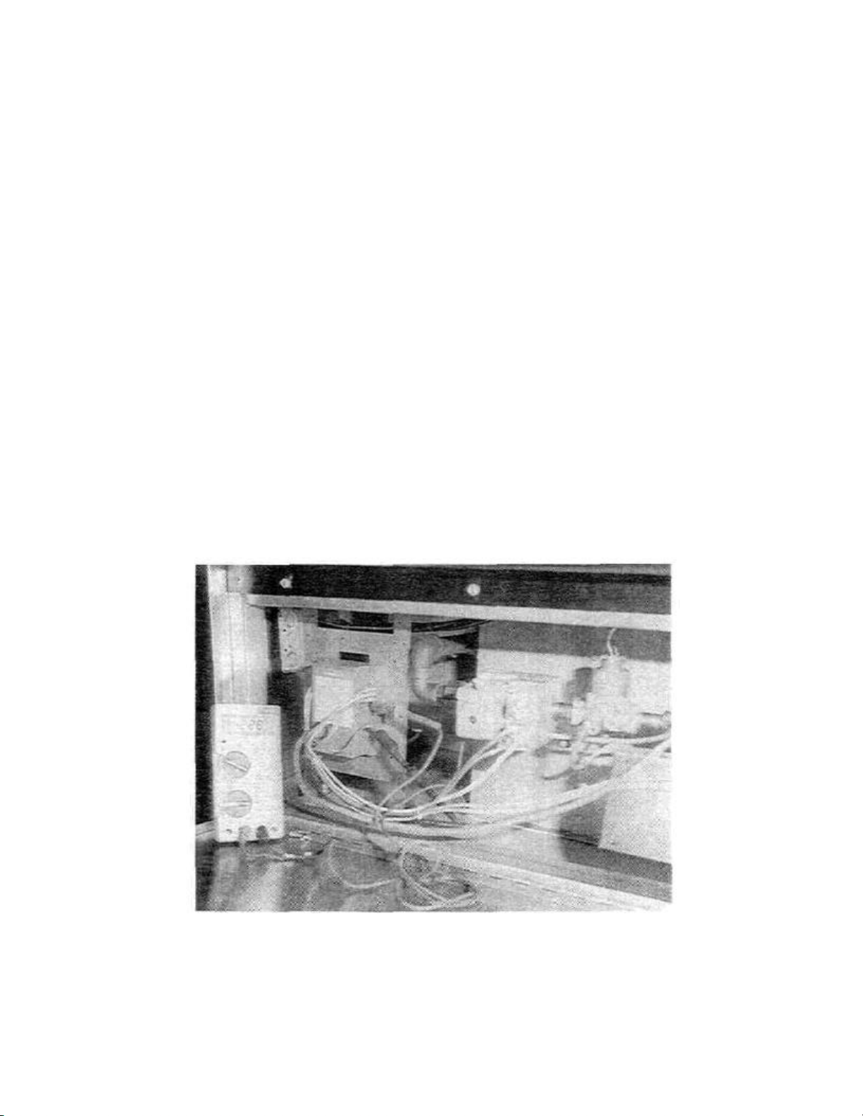
SECTION
2
SERVICING
3. Control Module Flame Sensor Circuit Test
COMPONENTS
4. System Troubleshooting. Referto next page
The control module provides AC power to the
ignitor/sensor which the pilot burner flame rectifies to
direct current. If the flame signal back to the control
module is not at least 1.5 uA DC, the system will lock
out.
The output of the flame sensing circuit cannot be
checked directly, so check the flame sensing circuit
indirectly by checking the flame sensing current form
the ignitor/sensor to the control module as follows.
a. Connec t a meter (DC microammeter scale) in
series with the flame signal ground wire as shown in
Figure 49. Use the HoneyweII W 136A Test Meter, or
equivalent. Disconnect the ground wire at the control
module. Connect the red (positive) lead of the meter to
the free end of the ground wire. Connect the black
(negative) meter lead to the quick-connect ground
terminal on the control module.
b. Restart the system and read the meter. The
flame sensor current must be at least 1.5 uA, and the
reading must be steady. If the reading is below the
value designated above or the reading is unsteady,
check the pilot flame and electrical connections as
described above. Also, replace the ignitor/sensor if the
ceramic insulator is cracked.
Start the system by setting the temperature controller
above room temperature, and observe the system
response.
Establish the type of system malfunction or deviation
from normal operation by using the 360 Intermittent
Pilot System Troubleshooting Table which follows.
Use the table by following the questions in the boxes. If
the condition is true (answers yes), go down to next
box. if the condition is not true (answers no), go to the
box alongside.
Continue checking and answering conditions in each
box until a problem and/or the repair is explained. Use
the COMPONENT CHECKS section (beginning on
page 50) as necessary to perform system checks.
After any maintainance or repair, the troubleshooting
sequence should be repeated until the procedure ends
with normal system operation.
Figure 49. Burner Ignition
System with AMP/OHM
Meter (Shaon on Model
PS360)
47
Page 74

SECTION 2 SERVICING
COMPONENTS
IMPORTANT: When servicing the Burner Control Board it is very
important that you identify the Control Board as either a fused or a
nonfused. The original board supplied by the vendor for the past few
years was the fused model. We are now supplied with the nonfused
mode. All PS200 ovens have the nonfused model.
Refer to the chart below when servicing the Burner Control or the Gas
Safety Valve.
MV/PVtoPV 3 VAC 24 VAC
MV/PVtoMV 12 VAC 24 VAC
BURNER CONTROL BOARD
Voltage Test Points Marked
Fused Nonfused
TRtoTH 12 VAC 24 VAC
TH/TRtoTR 3 VAC 24 VAC
MAIN GAS VALVE
The nonfused Ignition Control Board has been used in production
since early 1988 on all PS310, 360 and 200 Model Ovens. This is also
the only board now supplied by Middleby Marshall as a replacement
part.
48
Page 75

Service Bulletin
Date
11/30/90
NO. 123A
A MIDDLEBY COMPAHY
SUBJECT: HONEYWELL IGNITION MODULE
All Pacesetter Ovens
We spoke "too soon. There is a difference between the current Honeywell ignition module (P/N 27161-0004) and
the new Honeywell ignition module (P/N 27161-0005; Kit P/N 42810-0114), introduced to you in Service Bulletin
123.
The new module is internally grounded and as a result must not be in the ground leg of the 24 volt transformer.
Double grounding of the new module sets up a feedback voltage circuit allowing the module to operate without
signal from the burner/blower assembly.
WHEN REPLACING AM OLD MODULE WITH A MEW MODULE IT IS MANDATORY TO REMOVE AND DISCARD THE
BURNER TRANSFORMER GROUND WIRE. SEE FIGURE 1 OF INSTRUCTIONS ATTACHED.
This ground wire is located inside the burner/blower motor electrical box containing the 24 volt transformer and
prepurge relay. The green ground wire is secured by a ring terminal at the base of the transformer and runs from a
wire nut which ties the yellow ground lead from the ignitor module with the yellow wire from the transformer and the
black wire from the prepurge relay coil. It is the green wire only that is to be removed.
This change however, does not eliminate the need for the ground wire in cases where a technician is using the
older module as a replacement in an oven which was already fitted with a new module and no ground wire.
If an old module is replacing a new module then the ground wire needs to be replaced for the older module to
operate properly. See Figure 2 of instructions attached.
IN REVIEW
1. NEW MODULE MUST NOT HAVE GROUND WIRE (FIG. 1).
2. OLD MODULE MUST HAVE GROUND WIRE (FIG - 2).
We appreciate your usual and kind cooperation in this matter.
James E. Urani
Field Technical Supervisor
8300 Austin Avenue • Morton Grove, Illinois 60053
(708)-966-8300• FAX (708)966-8701
JEU:aa
48A
Page 76

INSTALLATION INFORMATION (P/N 88210-0058) NEW HONEYWELL IGNITION
MODULE (P/N 27161-0005) OLD HONEYWELL IGNITION MODULE (P/N 27161-0004)
REPLACING OLD MODULE WITH NEW
1. WHEN REPLACING AN OLD MODULE WITH A NEW MODULE IT IS MANDATORY TO REMOVE AND DISCARD THE BURNER
TRANSFORMER GROUND WIRE. SEE FIGURE 1.
This ground wire is located inside the burner/blover motor electrical box containing
the 24 volt transformer and prepurge relay. The green ground wire is secured by a
ring terminal at the base of the transformer and runs from a wire nut which ties the
yellow ground lead from the ignitor module with the yellow wire from the transformer
and the black wire from the prepurge relay coil. It is the green wire only that is
to be removed.
2. When reconnecting the module wires, be sure that the yellow wire which is actually
the ground wire is connected to the top terminal marked 24v (GND) on the new module.
3. If using existing ignitor/sense lead from old module, reconnect to new module using
adapter. See Figures 3 and 4.
4. When new ignitor/sense lead becomes available, the adapter will no longer be needed
and the ignitor/sensor lead will connect to the new module as called out in Figure 5.
REPLACING NEW MODULE WITH OLD
1. WHEN REPLACING A NEW MODULE WITH AN OLD MODULE IT IS MANDATORY TO INSTALL A BURNER TRANSFORMER
GROUND WIRE. SEE FIGURE 2-
Use a green 18 AWG, 105 degree C, U.L. listed wire and terminal ring. This ground
wire should be located inside the burner/blower motor electrical box containing the
24 volt transformer and prepurge relay. The green ground wire should be secured by a
ring terminal at the base of the transformer and run into the wire nut which ties the
yellow ground lead from the ignitor module with the yellow wire from the transformer
and the black wire from the prepurge relay coil.
2. When reconnecting the module wires be sure the yellow wire which is actually the
ground wire, is connected to the top terminal marked 24v on the old module.
3. Reconnect the ignitor/sense lead to spark terminal of old
module. The adapter in Figure 4 of the new module is not used.
NOTE: The new style ignitor/sense lead as shown in Figure 5 will not be compatible
with the old module. Either a new module must be used or the ignitor/sense lead must
also be replaced with an old style.
48B
Page 77
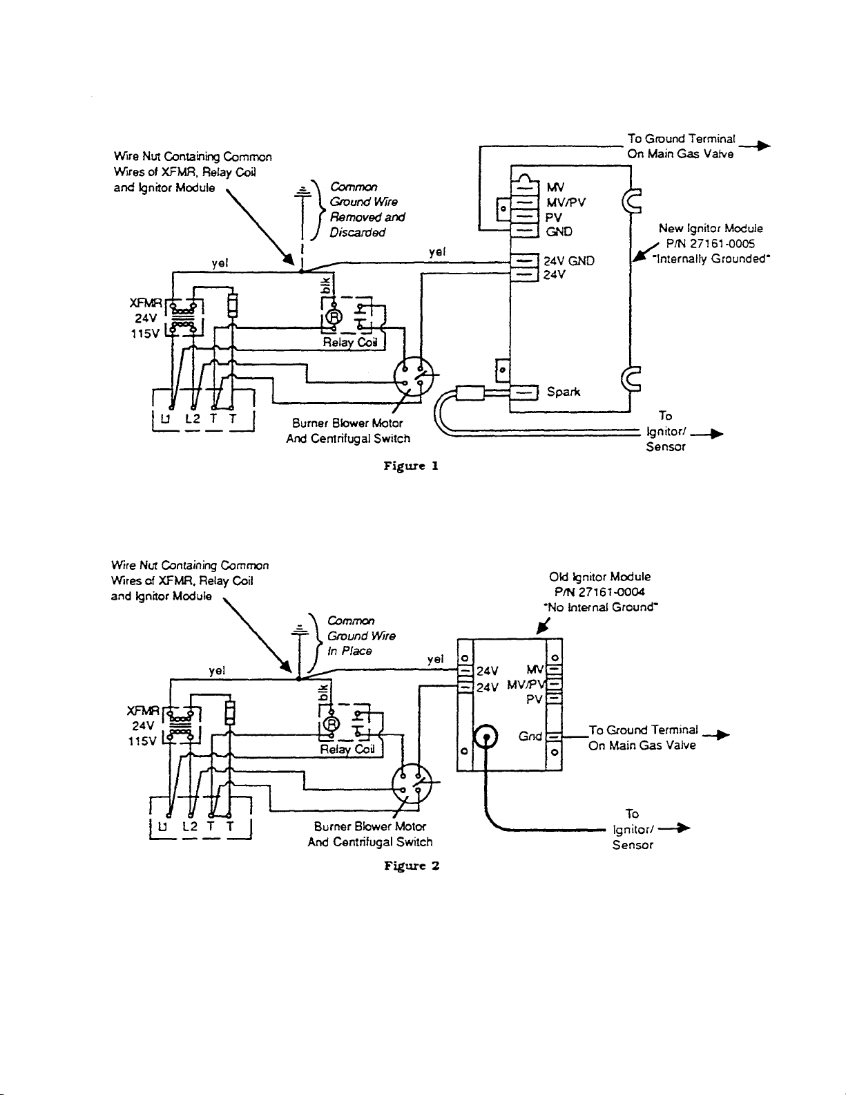
48C
Page 78
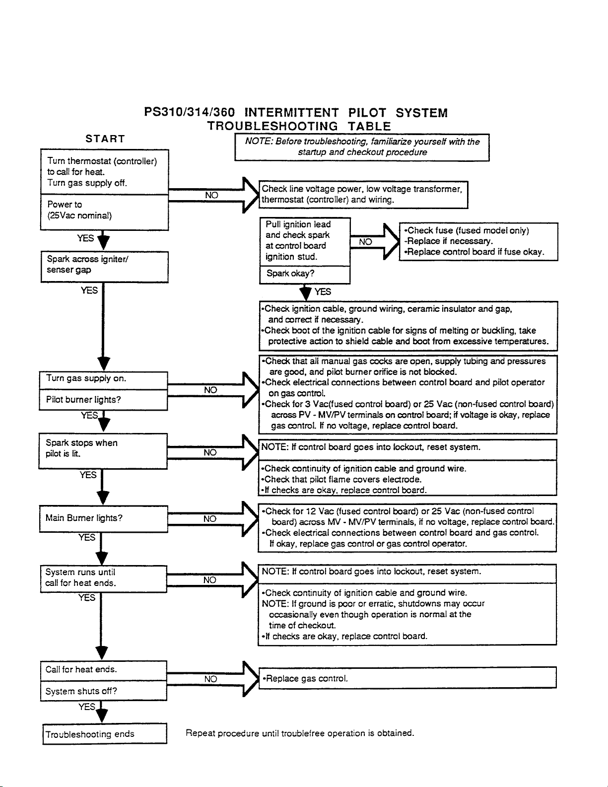
SECTION 2 SERVICING
COMPONENTS
Page 79
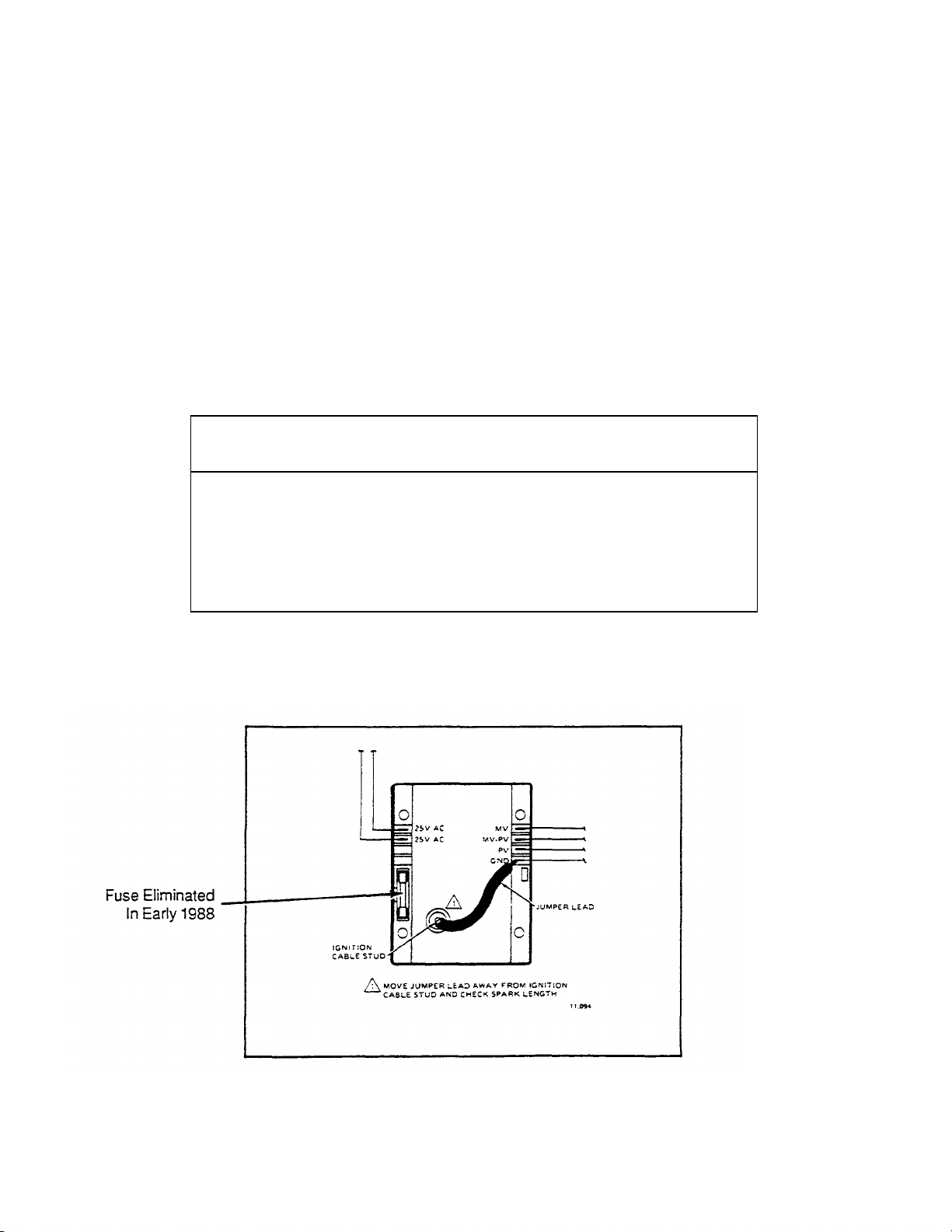
SECTION
2
SERVICING
COMPONENTS
5. Component Checks
Reset System After Lock out.
If a system with a control board goes into safety
lockout, the module must be reset before attempting
further operation or checkout. The system will remain
in safety lockout until it is reset. Shut system OFF.
(Turn Heat switch OFF).Wait at least one minute, then
turn Heat switch ON.
b. Disconnect the ignition cable at the control board
stud terminal to isolate the circuit from the pilot
burner/ignitor sensor, and prepare a short jumper lead
using heavily insulated wire, such as ignition cable.
c. Energize the control board and touch one end of
the jumper firmly to the control board ground terminal
(GND). Do not disconnect the existing ground lead.
Move the free end slowly toward the stud terminal to
establish a spark and then pull the leadwire slowly
away from the stud. Note the length of the gap at which
arcing stops (Figure 50).
6. Check Spare Ignition Circuit.
The electronic module and step-up transformer in the
control board provides spark ignition at 15,000V (open
circuit). This circuit can be checked at the control
board as follows:
a. Turn OFF the manual gas cock to prevent the
flow of gas.
CAUTION
Do Not touch either stripped end of jumper or stud terminal.
This is a very high voltage circut and electrical shock can result.
Perform the test immediately upon energizing the system-
before the control board goes into safety lockout
and interrupts the spark circuit.
d. An arc length of 1/8" (3.2mm) or more indicates
satisfactory voltage output. Replace the control board if
no arc can be established or the maximum gap is less
than 1/8" (3.2mm), and the fuse and power to the
control board input terminal was okay.
Figure 50. Checking Spark Ignition Circuit.
50
Page 80

7. Check Spark Ignitor.
If the troubleshooting procedure indicates a problem
with the ignitor/sensor, check the spark ignitor and the
ignitron cable connections and continuity as follows:
Check Ignitor/Sensor—
a. Check the ignitor spark gap to make certain it is
correct, 1/8" (3.2mm). If necessary, use a needlenose
plier and carefully bend the tip of the outer electrode to
correct.
b. Check that the pilot flame is properly adjusted.
See Check Pilot Flame, page 41.
Check Igniton Cable—
a. Ignition cable must not touch metal surfaces or
current carrying wires. Use ceramic standoff
insulators, if necessary.
b. Check length of ignition cable. It must not
exceed 3 ft. (0.9m).
SECTION 2 SERVICING
COMPONENTS
c. Check connections to ignitor and control module
stud, connections must be clean and tight. Loose
connections may not conduct a flame current even
though the ignition spark is satisfactory. Check the
electrical continuity of the cable. Replace cable if
damaged or deteriorated.
d. If no spark or a weak spark occurs, but spark
ignition circuit check was okay, disconnect the ignition
cable at the ignitor (or ignitor/sensor) and measure the
arc from the cable end to the ignitor stud. Follow the
same general procedures and observe the same
cautions as in Check Spark Ignition Circuit.
If the arc is correct, replace the ignitor (or
ignitor/sensor).
If the arc is less than it should be, disconnect the
ignition cable and use a jumper wire from the control
module stud terminal. If the spark is okay, replace the
ignition cable. If the arc is still less than it should be,
replace the control board.
51
Page 81
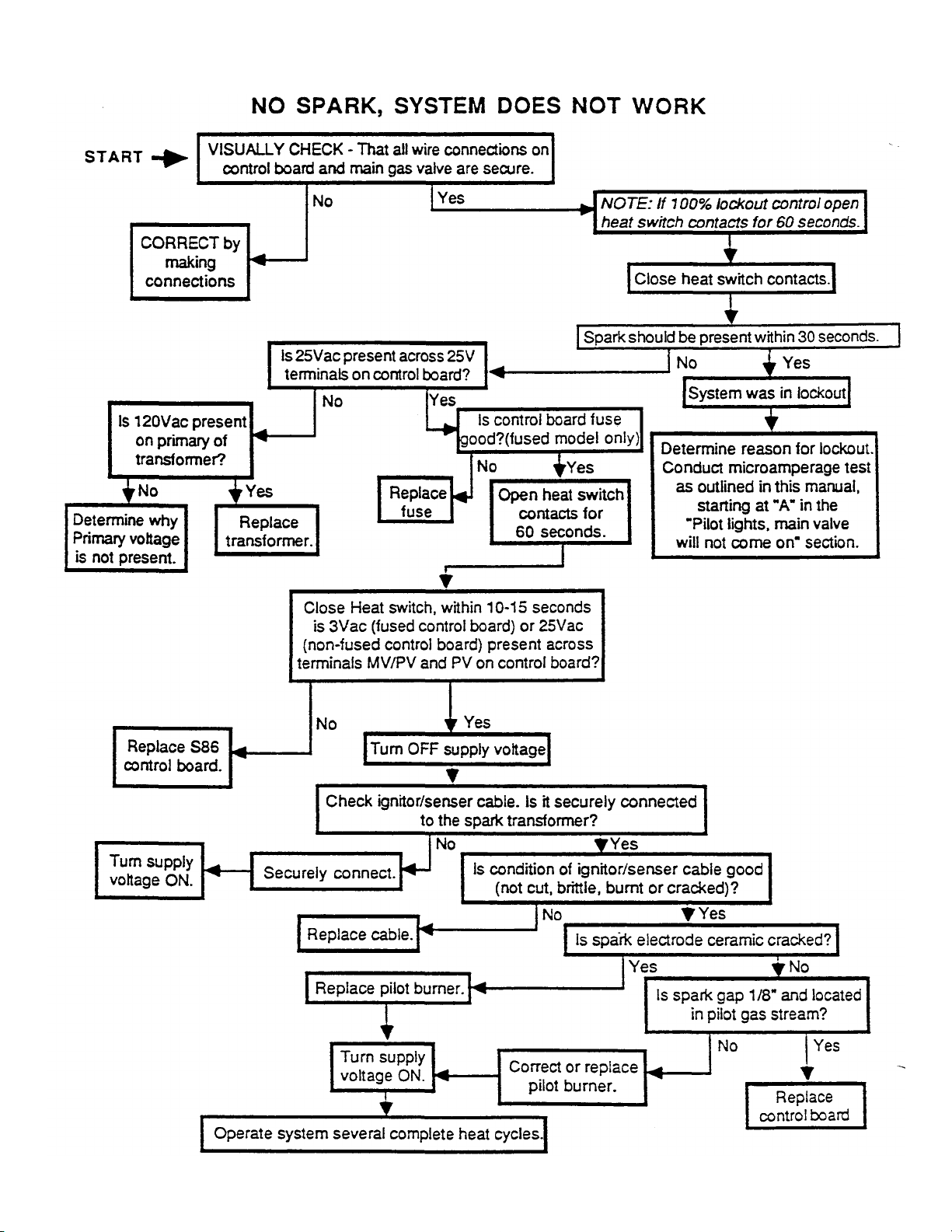
SECTION
2
SERVICING COMPONENTS
F. Checkout Procedures.
52
Page 82
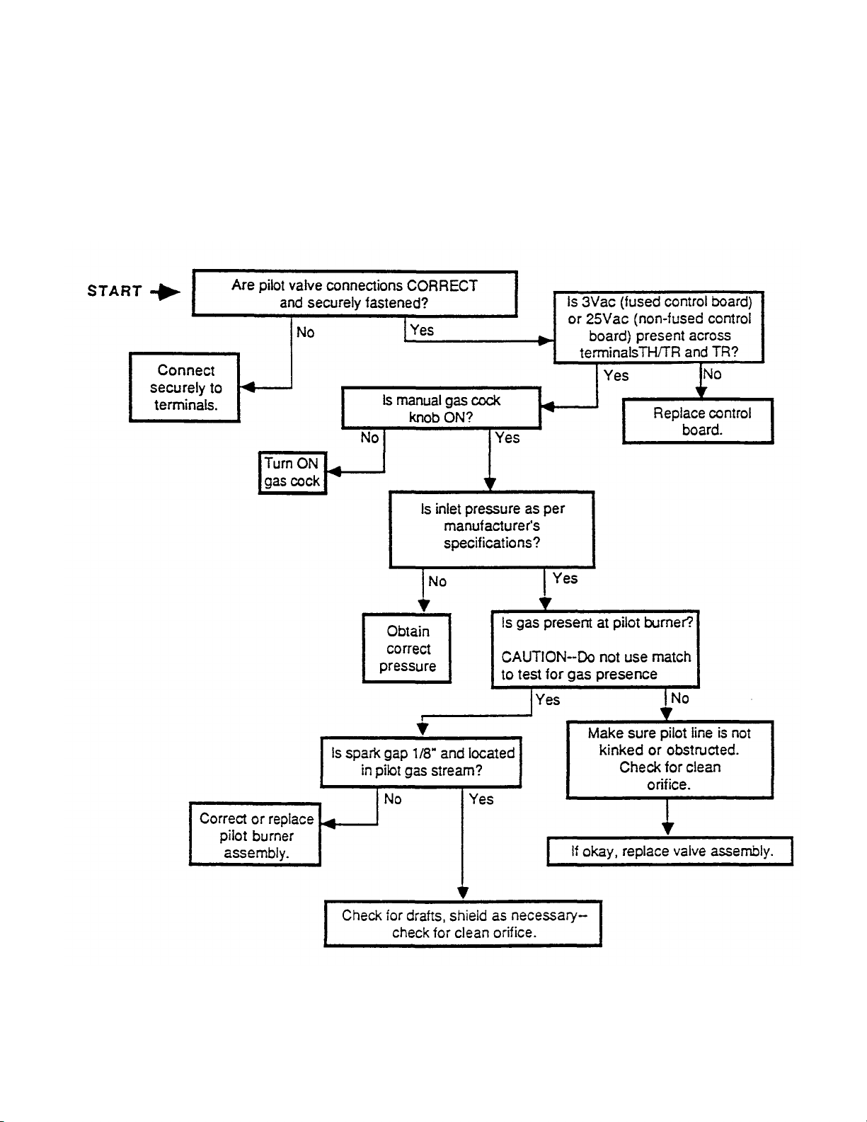
SPARK IS PRESENT, PILOT WILL NOT LIGHT
SECTION 2 SERVICING
COMPONENTS
53
Page 83
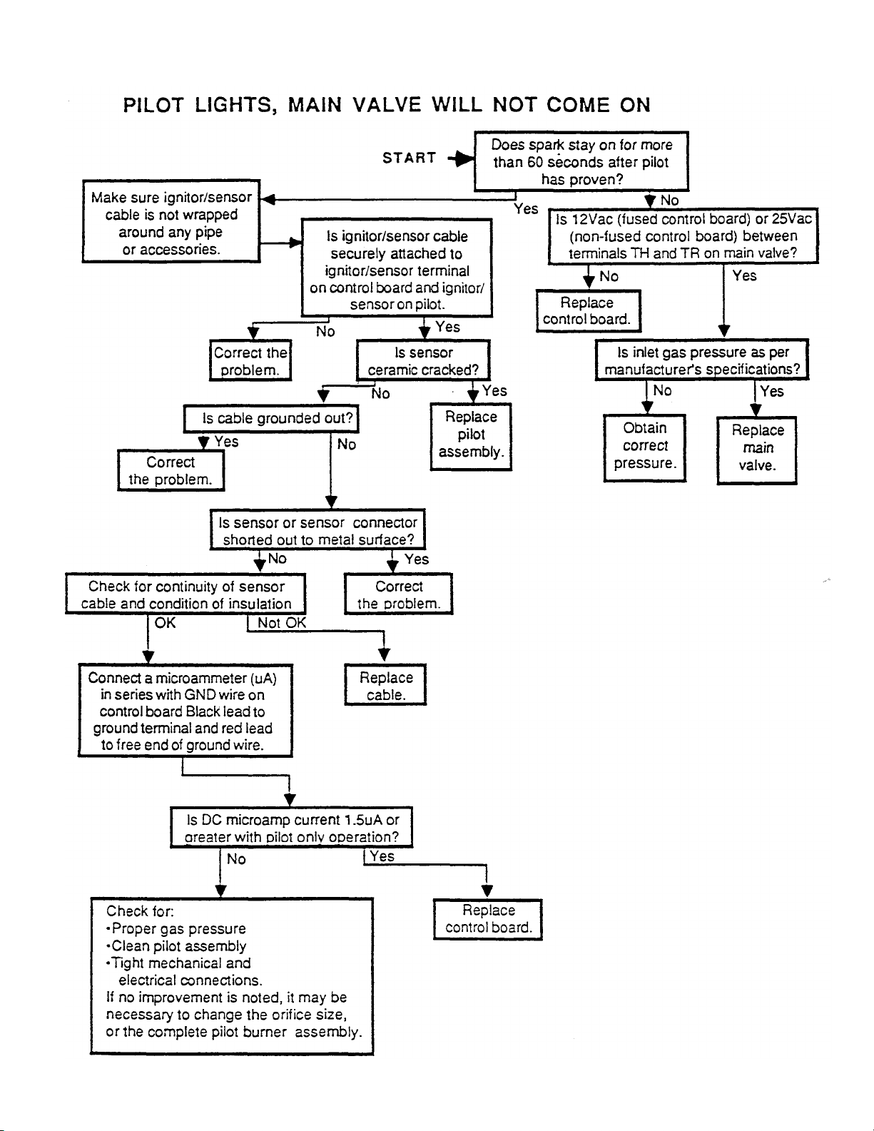
SECTION 2 SERVICING
COMPONENTS
54
Page 84
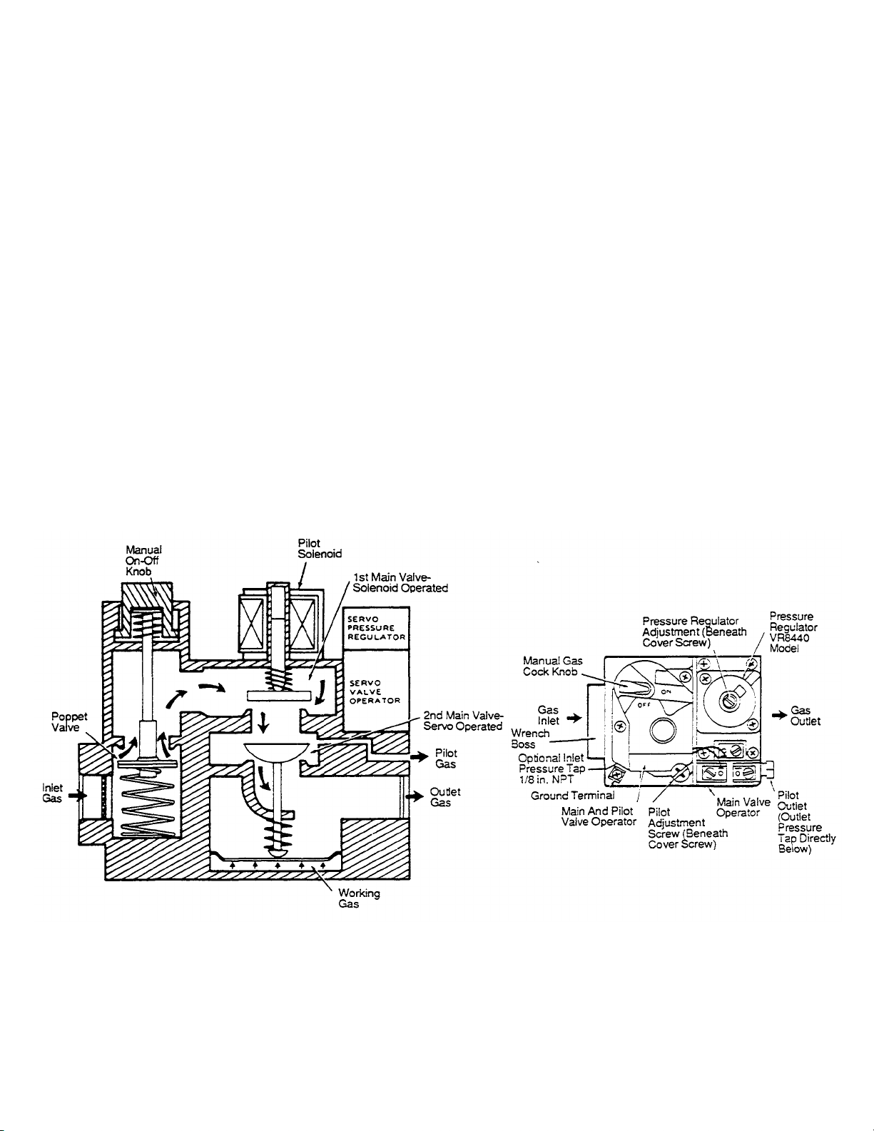
VI. HIGH FLAME SOLENOID VALVE
High flame solenoid valve is located between the gas
valve and the burner. This 110 volt valve is controlled
by the thermostat. When the thermostat calls for heat
the valve opens and lets the full flow of gas go to the
burner. When the thermostat is satisfied the valve
closes and the only gas going ot the burner is from the
by-pass line that goes around the solenoid valve body.
VII. MAIN GAS VALVE (MMPN 28092-0013).
When the Manual ON-OFF knob is turned to the ON
position gas is allowed to enter the valve through the
poppet valve. Once 24 Vac is supplied to the terminals
TH-TR and TR the pilot valve (solenoid operated)
opens which admits gas to the pilot burner, gas is not
yet allowed to the main burner. When the pilot flame is
SECTION 2 SERVICING
COMPONENTS
proved, 25Vac is applied to terminal TH -TR and TH,
energizing the Servo Valve Operator. The main valve
is Servo operated. Gas pressure from the inlet side of
valve is passed through the Pressure Regulator which
then supplies this regulated pressure to a cavity below
the main valve diaphragm. This pressure overcomes
the spring force and moves the main valve to its open
position. During operation the main valve is opened
and closed by the pressure regulator to keep a
constant pressure at the outlet of the valve.
When the Servo Valve operator is de-energized, the
cavity below the main valve diaphragm is
depressurized and the valve spring closes the main
valve rapidly to shut off the main burner.
When the pilot valve is de-energized the main solenoid
valve closes shutting gas OFF to the pilot and main
burner.
Figure 51. Main Gas Valve.
55
Page 85

SECTION 2 SERVICING
COMPONENTS
VIII. LOW FLAME ORIFICE
All ovens are equipped with an orifice in the low flame
gas line (See Figures 46 or 47). The purpose of this
orifice is to maintain a very low flame when the oven is
not calling for heat.
If the orifi ce size is too large the low flame will be too
high and in some cases this will cause the temperature
to raise overthe setting of the temperature controller.
The normal low flame orifice size is as follows:
Propane ft 62 Drill - MM P/N 22174-0009
Natural # 53 Drill - MM P/N 22174-0006
On PS360 ovens with the thermocouple located in the
rear of oven and all PS200 ovens the ratio of low flame
to high flame will be closerto 1 to 1.
NOTE: These readings should be taken after the oven has
stabilized (on for over an hour) and the oven moderately loaded with
product.
The high flame/low flame cycle time can be easily
determined by watching and timing the length of time
the high flame light of the temperature controller goes
on and off. When this light is on, the high flame solenoid
valve is energized (open).
High Altitude Exceptions
On PS360 ovens with the thermocouple located in the
front of oven and the low flame line having the proper
orifice, the ratio of low flame as compared to high flame
should be 2 or 3 to 1.
Example: If the high flame is on for 5 seconds, the low
flame should be on for no longer than 15 seconds. If it is
on longer than that the low flame orifice should be
replaced with one with a smaller hole.
Higher altitude will disrupt air fuel mixtures and
necessitate smaller orifices. A general rule is 4% input
reduction for every 1000 feet above sea level.
Example: At Denver, Colorado, (elevation of 5,000 feet)
the natural gas by -pass line will probably require a #54
orifice and the main burner should have a #8 orifice.
56
Page 86

2.
3.
4.
Service Bulletin
No. 131
SUBJECT: INTERMITTENT PILOT COMBINATION GAS CONTROL KIT PART NUMBER 42810-0121
The gas control kit, P/N 42810-0121, described in this bulletin is a direct
replacement for gas control P/N 28092-0013 which has been discontinued. The new
gas control kit consists of four (4) parts:
Part Number Description
1.
28092-0017
33300-0225
23070-0005
88210-0068
Gas Control
Pilot Tube
Compression Nut w/Sleeve
Instruction Sheet
AVAILABILITY
After November 14, 1991, all orders for gas control P/N 28092-0013
will be filled with the new gas control kit P/N 42810-0121.
Date 11/27/91
A MIDDLEBY COMPANY
DISPOSITION OF INVENTORY
Existing inventories of discontinued control P/N 28092-0013 should be used up.
FEATURES The new gas control provides four new features:
1. Easy access inlet and outlet pressure taps.
2. Easy conversion from natural to propane or propane to natural.
3. Wiring terminal nomenclature matches the ignition module.
4. On/off knob material is resistant to oven environment.
COMPATIBILITY
The new control will fit in all existing applications of the discontinued control.
However, due to the new location of the pilot tube outlet it will be necessary to
install the longer pilot tube which is supplied in the kit.
Conversion from natural to propane gas is done by changing the regulator spring
only. Refer to Service Bulletin 132 for details.
Tom Hoe Product Service Representative
TM:aa
8300 Austin Avenue • Morton Grove, Illinois 60053
(708) 966-8300 • FAX (708) 966-8701
56A
Page 87

FIRE OR EXPLOSION HAZARD
CAN
CAUSE PROPERTY DAMAGE,
natural gas on propane gas or a gas control set
for propane gas on natural gas
These gas controls are shipped with protective seals
until ready to connect piping
FIRE OR EXPLOSION HAZARD
SEVERE INJURY OR DEATH
No replaceable components. Attempted disassembl
y Or repair may damage the gas control.
©1992
Middleby Marshall
Part Number88210
-
0068
Middleby Marshall Inc. ·8300 Austin Ave. ·Morton Grove, IL 60053·(708)966-8300·TWX9102330211·FAX (708)966-8701
Intermittent Pilot Combination Gas Control
Kit (Kit Number 42810-0121)
Installation Instructions
WARNING
SEVERE INJURY OR DEATH.
Do Not attempt to use a gas control set for
IMPORTANT
over Inlet and outlet tapping. Do Not remove seals
WARNING
CAN CAUSE PROPERTY DAMAGE,
Do Not Disassemble the gas control; It Contains
The following Instructions describe the Installation of the Middleby Marshall gas control kit, MMP/N 42810-0121,
which is the replacement for the discontinued gas control MMP/N 28092-0013. The new gas control kit consists of
four (4) parts:
1 28092-0017 Gas Control
2 33300-0226 Pilot Tube
3 23070-0085 Compression Nut w/Sleeve
4 89210-0068 Instruction Sheet
The new control will fit in all existing applications of the discontinued control, however, due to the new pilot outlet
location it is necessary to install the longer pilot tube supplied in the kit.
Middley Marshall Inc.· 8300 Austin · Morton Grove IL. 60053· TWX9102230211· FAX (708)966-8701
P1/92
Page 88
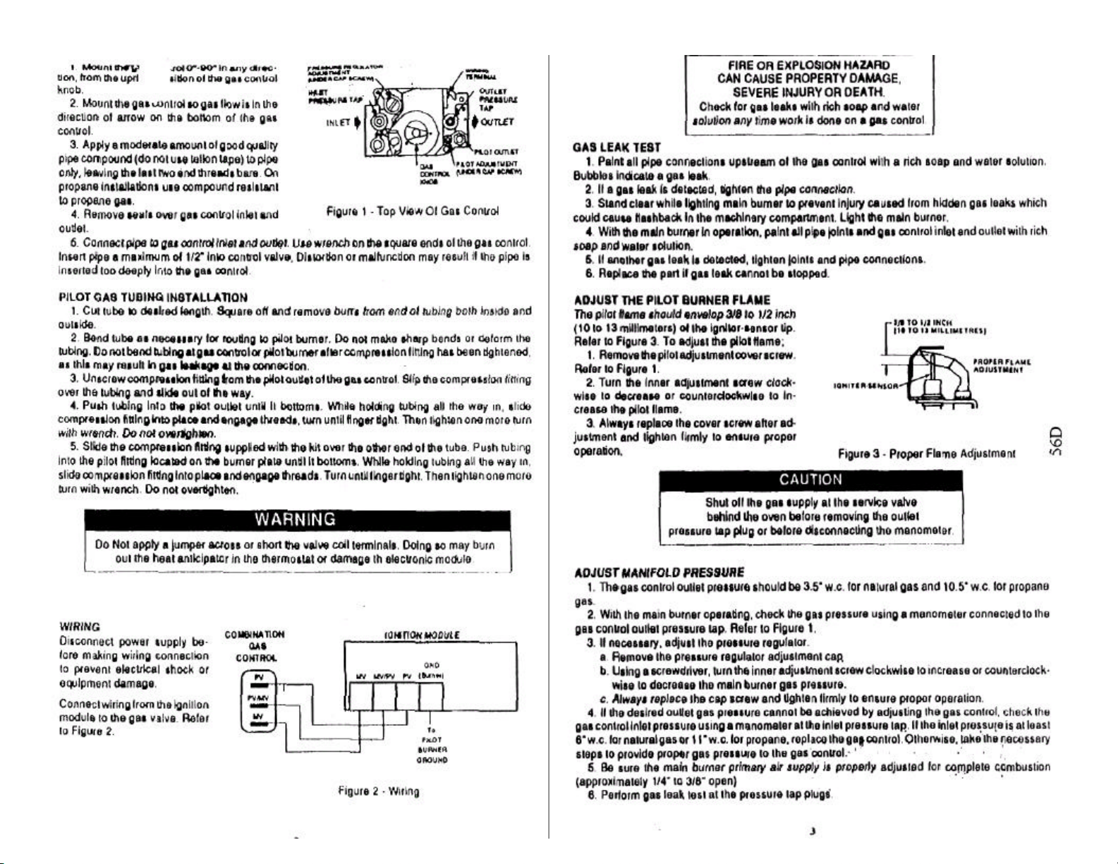
Page 89

56E
Page 90

SECTION 2 SERVICING
2 3 3 4 5 6 7 9 10 12
5 7 8 9 10 12 13 14 15 17
9 11 12 12 13 14 16 17 18 19
12 13 14 15 16 17 17 18 19 20
15 16 17 17 18 19 20 20 22 24 16 17 18 18 19 19 20 22 23 25
18 19 19 20 21 22 23 24 26 27
20 22 22 23 24 25 26 27 28 29 21 23 23 24 25 26 27 28 28 29
23 25 25 26 27 27 28 29 29 30
26 27 28 28 28 29 29 30 30 30
28 29 29 29 30 30 30 30 31 31 29 29 30 30 30 30 31 31 31 32
33 35 35 36 36 37 38 38 40 41
36 37 38 38 39 40 41 41 42 43
39 40 41 41 42 42 43 43 44 44
41 42 42 42 43 43 44 44 45 46
44 45 45 45 46 47 47 48 48 49 45 46 47 47 47 48 48 49 49 50
Equivalent Orifice Sizes at High Altitudes
(Includes 4% Input Reduction for Each 1,000 Feet)
COMPONENTS
Size at
Sea Level
1 2 2 3 3 4 5 7 8 10
3 4 5 7 8 9 10 12 13 15
4 6 7 8 9 11 12 13 14 16
6 8 9 10 11 12 13 14 16 17
7 9 10 11 12 13 14 15 16 18
8 10 11 12 13 13 15 16 17 18
10 12 13 13 14 15 16 17 18 19
11 13 13 14 15 16 17 18 19 20
13 15 15 16 17 18 18 19 20 22
14 16 16 17 18 18 19 20 21 23
17 18 19 19 20 21 22 23 24 26
19 20 20 21 22 23 25 26 27 28
22 23 24 25 26 27 27 28 29 29
24 25 26 27 27 28 28 29 29 30
25 26 27 27 28 28 29 29 30 30
2000 3000 4000 5000 6000 7000 8000 9000 10000
Orifice Size Required at Other Elevations Orifice
27 28 28 29 29 29 30 30 30 31
30 30 31 31 31 31 32 32 33 35
31 32 32 32 33 34 35 36 37 38
32 33 34 35 35 36 36 37 38 40
34 35 36 36 37 37 38 39 40 42
35 36 36 37 37 38 39 40 41 42
37 38 39 39 40 41 42 42 43 43
38 39 40 41 41 42 42 43 43 44
40 41 42 42 42 43 43 44 44 45
42 42 43 43 43 44 44 45 46 47
43 44 44 44 45 45 46 47 47 48
46 47 47 47 48 48 49 49 50 50
57
Page 91

SECTION 2 SERVICING
Sea Level
COMPONENTS
Size at
47 48 48 49 49 49 50 50 51 51
48 49 49 49 50 50 50 51 51 52
49 50 50 50 51 51 51 52 52 52
50 51 51 51 51 52 52 52 53 53
51 51 52 52 52 52 53 53 53 54
52 52 53 53 53 53 53 54 54 54
53 54 54 54 54 54 54 55 55 55
54 54 55 55 55 55 55 56 56 56
55 55 55 55 56 56 56 56 56 57
56 56 56 57 57 57 58 59 59 60
57 58 59 59 60 60 61 62 63 63
58 59 60 60 61 62 62 63 63 64
59 60 61 61 62 62 63 64 64 65
60 61 61 62 63 63 64 64 65 65
61 62 62 63 63 64 65 65 66 66
62 63 63 64 64 65 65 66 66 67
63 64 64 65 65 65 66 66 67 68
64 65 65 65 66 66 66 67 67 68
65 65 66 66 66 67 67 68 68 69
66 67 67 68 68 68 69 69 69 70
67 68 68 68 69 69 69 70 70 70
68 68 69 69 69 70 70 70 71 71
69 70 70 70 70 71 71 71 72 72
70 70 71 71 71 71 72 72 73 73
71 72 72 72 73 73 73 74 74 74
72 73 73 73 73 74 74 74 74 75
73 73 74 74 74 74 75 75 75 76
74 74 75 75 75 75 76 76 76 76
75 75 76 76 76 76 77 77 77 77
76 76 76 77 77 77 77 77 77 77
77 77 77 77 78 78 78 78 78 78
78 78 78 78 79 79 79 79 80 80
79 79 80 80 80 80 .013 .012 .012 .012
80 80 .013 .013 .013 .012 .012 .012 .012 .011
Equivalent Orifice Sizes at High Altitudes
(Includes 4% Input Reduction for Each 1,000 Feet)
Orifice Size Required at Other Elevations Orifice
2000 3000 4000 5000 6000 7000 8000 9000 10000
58
Page 92

SECTION
2
SERVICING
IX. PROPANE CONVERSION KIT
(MM P/N 42810-0027)
All ovens can easily be convened from Natural to
Propane or Propane to Natural gas by ordering and
installing the proper Conversion Kit.
ORIFICE KITS
See Conversion Kit breakdown below:
CONVERSION KITS PS200 NATURAL TO PROPANE GAS, KIT NO. 49810-0003
QTY PART NO. DESCRIPTION
1 22176-0007 Orifice, Main Burner 5/8 x 27 Thd - .1285" (#30 drill)
1 22174-0009 Orifice, Bypass #62
1 22174-0010 Orifice.Pilot.014
1 28092-0015 Regulator, Set Propane 11.0" WC
1 22500-0065 Label - Propane
PS200 PROPANE TO NATURAL GAS, KIT NO. 49810-0011 CONSISTS OF:
COMPONENTS
NOTE: Propane ovens shipped from the factory will
have the old natural gas orifice enclosed in a plastic
container. This is in the event that the oven may have
to be converted back to natural gas at some future
date. If an oven is field convened from natural to
propane please leave the old natural gas orifices in a
propane container inside the machinery compartment
of the oven.
Refer to Figure 46 or 47 for the location of the low
flame, main burner and pilot orifice.
CONSISTS OF:
QTY PART NO. DESCRIPTION
1 22176-0006 Orifice, Main Burner 5/8 x 27 Thd - .1960" (#9 drill)
1 22174-0006 Orifice, By pass #53
1 22174-0011 Orifice, Pilot .020
1 28092-0016 Regulator, Set Natural 3.5" WC
1 22500-0064 Label - Natural
PS310/360 NATURAL TO PROPANE GAS, KIT NO. 42810-0027 CONSISTS OF:
QTY PART NO- DESCRIPTION
1 22176-0003 Orifice, Main Burner 5/8 x 27 Thd - 3.44 mm
1 22174-0009 Orifice, By pass #62
1 22174-0010 Orifice, Pilot .014
1 28092-0015 Regulator, Set Propane 11.0" WC
1 22500-0065 Label-Propane
PS310/360 PROPANE TO NATURAL GAS, KIT NO. 49810-0026 CONSISTS OF:
QTY PART NO. DESCRIPTION
1 22176-0004 Orifice, Main Burner 5/8 x 27 Thd - 7/32'
1 22174-0006 Orifice, By pass #53
1 22174-0011 Orifice, Pilot .020
1 28092-0016 Regulator, Set Natural 3.5" WC
1 22500-0064 Label - Natural
59
Page 93
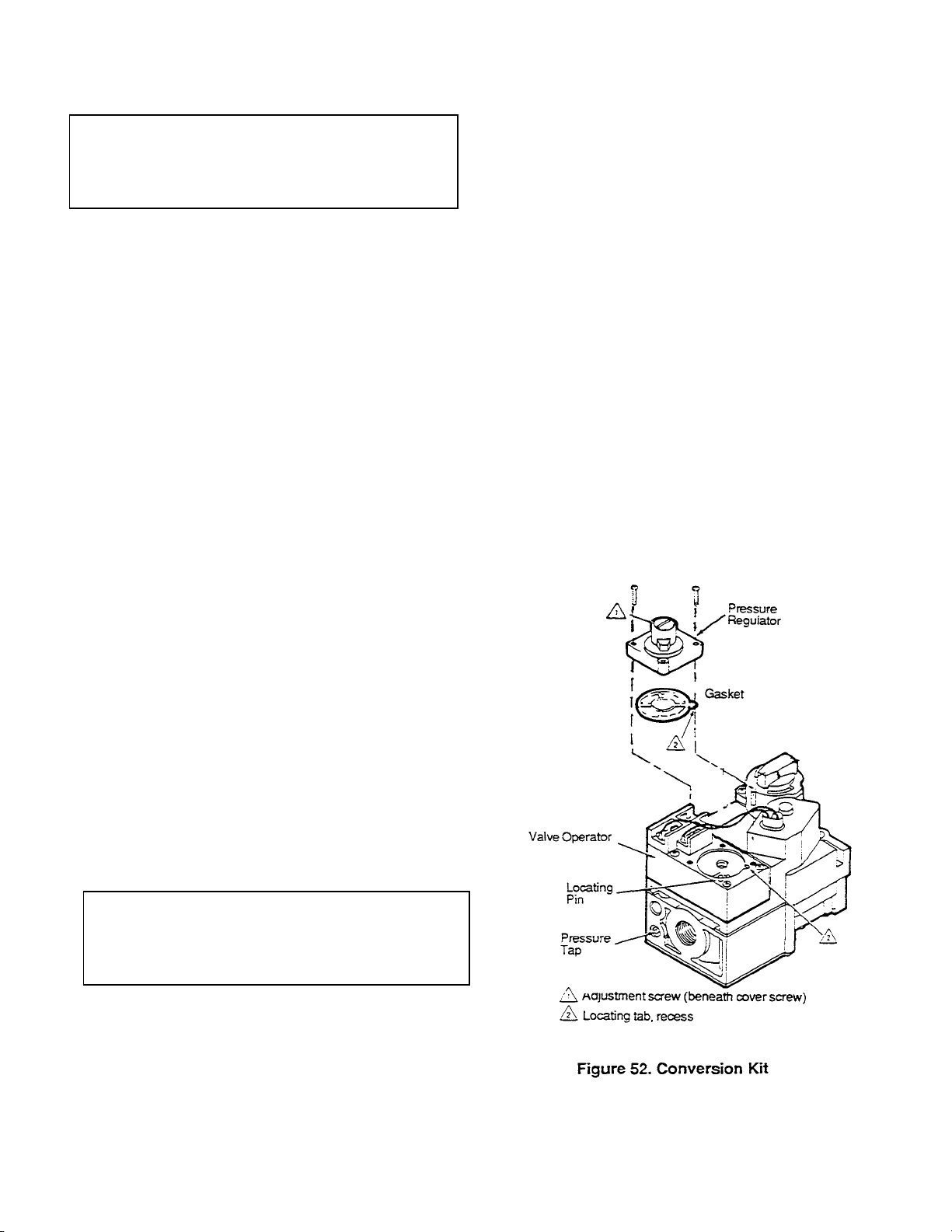
SECTION 2 SERVICING
A. Converting Gas Valve from Natural to Propane
CAUTION: Turn OFF gas at manual shutoff
1.
Loosen two Philips screws from Propane
CAUTION: Turn OFF gas at manual shutoff
COMPONENTS
Gas.
valve on incoming gas line before
attempting to loosen any gas fitting on the
oven. Also shut OFF main electrical
breaker for oven.
1. Loosen two Philips screws from Natural
pressure regulator and remove regulator and
gasket.
2. Attach Propane gas pressure regulator (MM
P/N 28092-0015) as shown in Figure 52. DO NOT
use old gasket, a new gasket is supplied with kit.
3. Attach gas pressure manometer to inlet and
outlet pressure taps of the gas valve.
4. Turn on gas supply and electrical power.
5. Incoming gas pressure MUST BE between 11"
WC and 14" WC.
6. Remove cover screw on regulator, turn on
Blower and Heat switches and allow oven to fire.
Adjust pressure regulator adjustment screw so
outlet pressure is 10.5"WC.
2. Attach Natural gas pressure regulator (MM P/N
28092-0016) as shown in Figure 52. DO NOT use
old gasket, a new gasket is supplied with kit.
3. Attach gas pressure manometer to inlet and
outlet pressure taps of the gas valve.
4. Turn on gas supply and electrical power.
5. Incoming gas pressure MUST BE between
6"WCand12"WC.
6. Remove cover screw on regulator, turn on
Blower and Heat switches and allow oven to fire.
Adjust pressure regulator adjustment screw so
outlet pressure is 3.5"WC.
7. If incoming gas pressure drops below 6"WC with
oven and all gas appliances in store on high flame
condition this indicates a problem with the incoming
gas supply.
8. Replace pressure regulator cover screw.
7. If incoming gas pressure drops below 11"WC
with oven burner ON this indicates a problem with
the incoming gas supply.
8. Replace pressure regulator cover screw.
9. IMPORTANT: Place adhesive backed
Propane sticker on visible side of gas valve,
10. With a felt tip pen change the marked setting
on the serial plate from Natural to Propane and
the pressure from 3.5" WC to 10.5" WC.
11. Check all gas connections for leaks.
B. Natural Conversion Kit
Converting Gas Valve from Propane to Natural
Gas
valve on incoming gas line before
attempting to loosen any gas fitting on the
oven. Also shut OFF main electrical
breaker for oven.
pressure regulator and remove regulator and
gasket.
60
Page 94

Middleby Cooking Systems Group
1400 Toastmaster Drive • Elgin, Illinois 60120
(708)741-3300 • Service & Parts (708) 741-4406
Service Bulletin
Bulletin No. 13 2 A
Date: 12/19/94
SUBJECT: PS360WB GAS CONVERSION KIT
GENERAL:
This bulletin is issued to alert the service technician that the PS360WB can be converted from natural to
propane, or from propane to natural as is possible with any other Middleby Marshall gas fired
conveyorized oven. This bulletin updates the natural to propane instructions, P/N 88210-0069, presented in
Service Bulletin 132.
APPLICATION:
To convert a PS360WB from natural to propane gas, use Kit ff 42810-0124. To convert a
PS360WB from propane to natural gas, use Kit it 42810-0127.
COMPATIBILITY:
The PS360WB gas conversion kits are the same as those used on the PS570 and PS570S ovens.
AVAILABILITY:
Kits 42810-0124 and 42810-0127 are available now for immediate shipment.
60A
Page 95
Authorized Service Or
ganization In accordance with the manufacturer's
instructions and all codes and requirements of the authority having
jurisdiction. Failure to follow Instructions could result
in serious injury or property damage. The authorized service organiza
- tion
performing this work assumes responsibility for this conversion.
Middleby Marshall Inc, • 8300 Austin Ave, •Morton Grove, IL 60063 • (708)966-8300 • 1-800-238-M44 • FAX(708)966-8701
Oven Gas Conversion Kit-
Natural Gas to Propane Gas
Installation Instructions
IMPORTANT
KITS LISTED BELOW ARE FOR USE WITH OVENS EQUIPPED WITH OAS CONTROL
VALVE MM/PN 28092-0017 ONLY!
PS360WB......…....................................... MM/PN 428104124
The following Instructions cover the Installation of the MIddleby Marshall Oven - Natural to Propane Gas
Conversion Kit. The Kit consists of the following parts:
DESCRIPTION PART NUMBER
Complete Gas
Kit Natural to Propane Gas 428104119 428104122 428104123 428104124
Orifice, Main Burner 221784003 221764007 221784017 221764015
Orifice, Bypass 221744009 (IK32 with red dot) (same for all models/series)
Orifice, Pilot 221744010 (0.014” with red dot) (same for all models/series)
Gas Control Valve
Conversion Kit 280924018 (same for all models/series)
Propane Label 225004005 (same for all models/series)
Oven Conversion Label 225004123 (same for all models/series)
Gas Control Conversion
Gas Oven Conversion
Instructions 882104009 (same for all models/series)
PS200 Kit ...............................................MM/PN 42810.0122
PS200-20 Kit........................................…MM/PN 428104123
PS300 Series (except P8333) Kit ....….....MM/PN 428104119
PS570 Kit .........................................…....MM/PN 428104124
WARNING
PS300 Series
(except PS333)
3.44mm 0.1285' 0,113' 0.152'
PS200 PS200-20 PS570 &
225014007 (same for all models/series)
P8360WB
©1992 Middlebly Marshall Part Number 88210-0069
Page 96
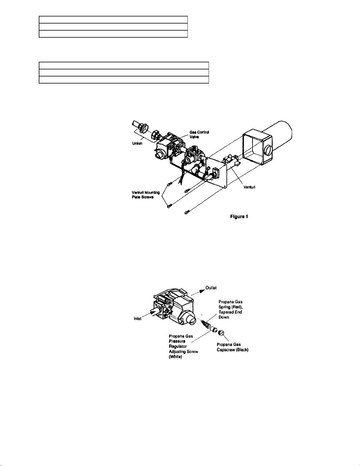
CAUTION
Figure
2
Turn Off The Electrical Power Supply To The Oven
Before Performing Any Service Or Conversion Work
CAUTION
Turn Off The Gas Supply At The Service Valve Behind The Oven
Before Performing Any Service Or Conversion Work
MANIFOLD AND VENTURI
REMOVAL
1. Turn off the electric power
supply to the oven.
2. Turn off the gas supply at the
service valve behind the oven.
3. Unscrew the gas pipe union located on the Inlet side of the gas
control, Refer to Figure 1.
4. Unscrew the four venturi
mounting plate screws. Refer to
Figure 1.
5 Remove the manifold and
venturi assembly from the oven.
Refer to Figure 1.
NOTE: The Manifold and venturi assembly shown in
Figure1 is from a
PSSOO Series Oven. The disassembly procedure is the same for all three series ovens (PS200,
PS300andPS500). The pipe union that is loosened is always at the inlet side o the gas control
valve.
GAS CONTROL VALVE CONVERSION
NOTE: The parts Installed In the following Steps 1-6 are found in the Gas Control
Conversion Kit M M/PN 2BW2-W1B, which Is Included here in this kit.
1. Remove regulator cap screw and
pressure regulator adjusting
screw. Refer to Figure 2.
2. Remove the existing spring.
3. Insert the red replacement
spring with the tapered and down.
Refer to Figure 2.
4. Install the new plastic pressure
regulator adjustment screw.
Ensure that the screw top is flush
with the regulator top,
5. Turn pressure regulator adjust ment screw clockwise six complete
turns. The preliminary pressure
setting Is approximately 10.5 In.
w.c.
6. Install the new black cap screw.
Page 97
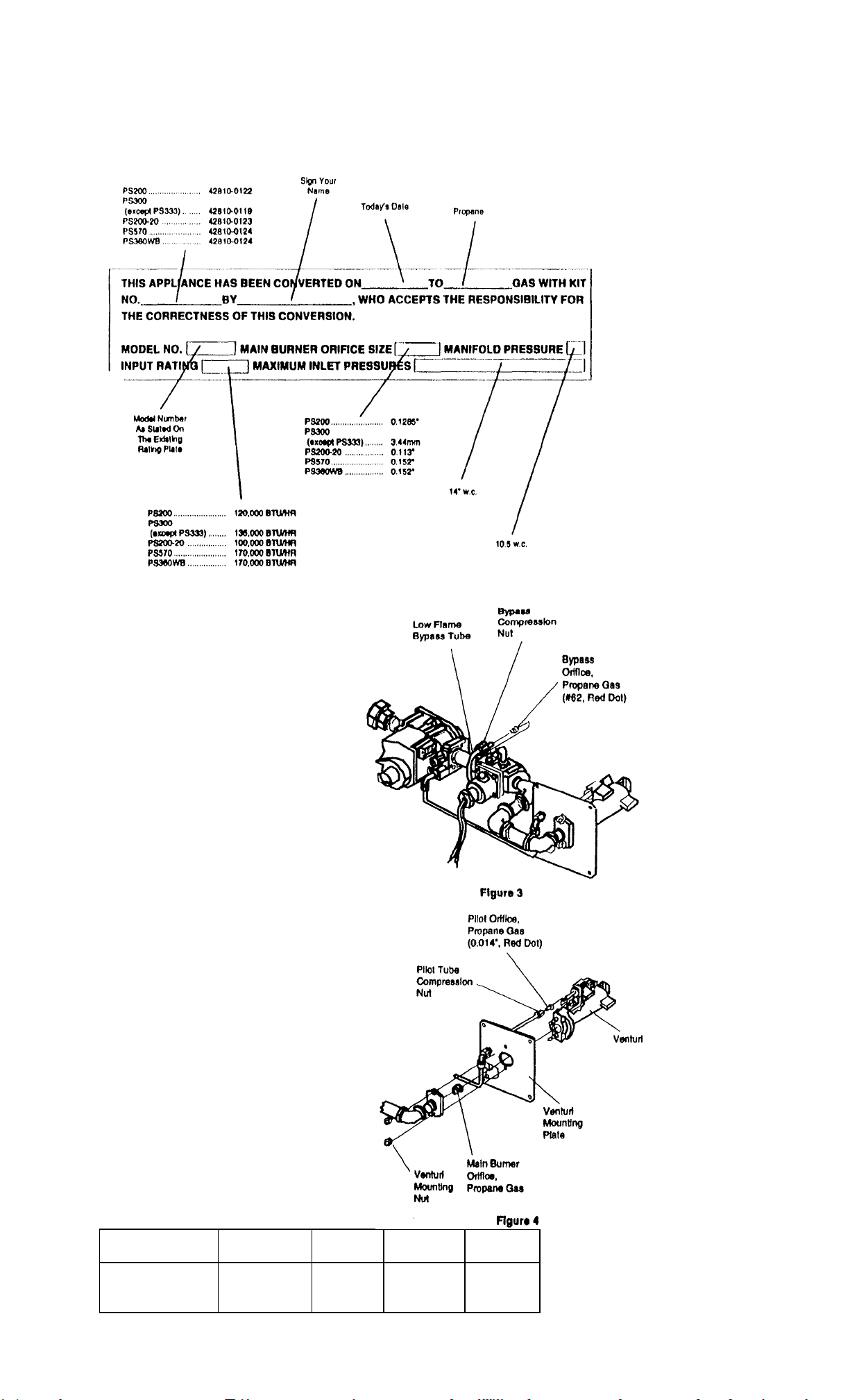
MARKING AND LABELING
1. Print the word 'PROPANE" In the space provided on the Gas Control Conversion Tag P/N
25501.0007.
2. Affix the Gas Control Conversion Tag on the gas control.
3. Affix the round, orange, propane label Part Number 22500-0065 over (TIB round, green
natural label on the burner (unction box cover.
4. Pill In the appropriate Information on me oven conversion label P/N 22500-0123 according to
the Instructions In Figure 0.
5. Affix the oven conversion label as close as possible to the existing rating plate.
Figure B
BYPASS ORIFICE CONVERSION
1. Unscrew the bypass tube compression
nut and slide out of the way Pull the tube from
the fitting to expose the bypass orifice as
shown in Figure 3.
2. Remove the existing natural gas bypass
orifice
3. Install the propane (K62 with the red dot)
bypass orifice by slipping II Into the bypass
tube.
4. Push the tube with the bypass orifice In
place, Into the solenoid valve fining until It
bottoms. While holding the tubing all the way
In, slide the compression nut Into place and
engage threads, turning ringer tight. Then
tighten one more turn with a wrench. Do Not
Overtighten.
PILOT ORIFICE CONVERSION
1. Unscrew the pilot lube compression nut and
slide out of the way. Pull the lube from the
fining to expose the pilot orifice as shown In
Figure 4.
2. Remove the existing natural gas pilot orifice.
3. Install the propane pilot orifice (0.014' with the
red dot) by slipping It Into the pilot tube.
4. Push the tube with the pilot orifice In place. Into
the solenoid valve fitting until it bottoms. While
holding the tubing all the way In, slide the
compression nut Into place and engage threads,
turning finger tight. Then tighten one more turn
with a wrench. Do Not Overtighten.
MAIN BURNER ORIFICE CONVERSION
1. Unscrew the two venturi mounting nuts,
(Early models equipped with screws). Refer to
Figure 4.
2. Separate the venturi, mounting plate, and
pipe.
3. Unscrew the existing natural gas main burner
orifice from the pipe.
4. Install the correct propane main burner
orifice. See Table 1 for orifice size and number.
5. Reinstall the venturi and pipe to the venturi
mounting plate.
TABLE 1 P8300 Series P8200 P8200-20 P8S70 &
Orifice Size 3.44mm 0.1285' 0.113" 0.152'
Orifice Marking 134 128 113 152
Orifice Part Number 22176-0003 22176-0007 22176-0017 22176-0016
(Except PS333)
P8360WB
Page 98
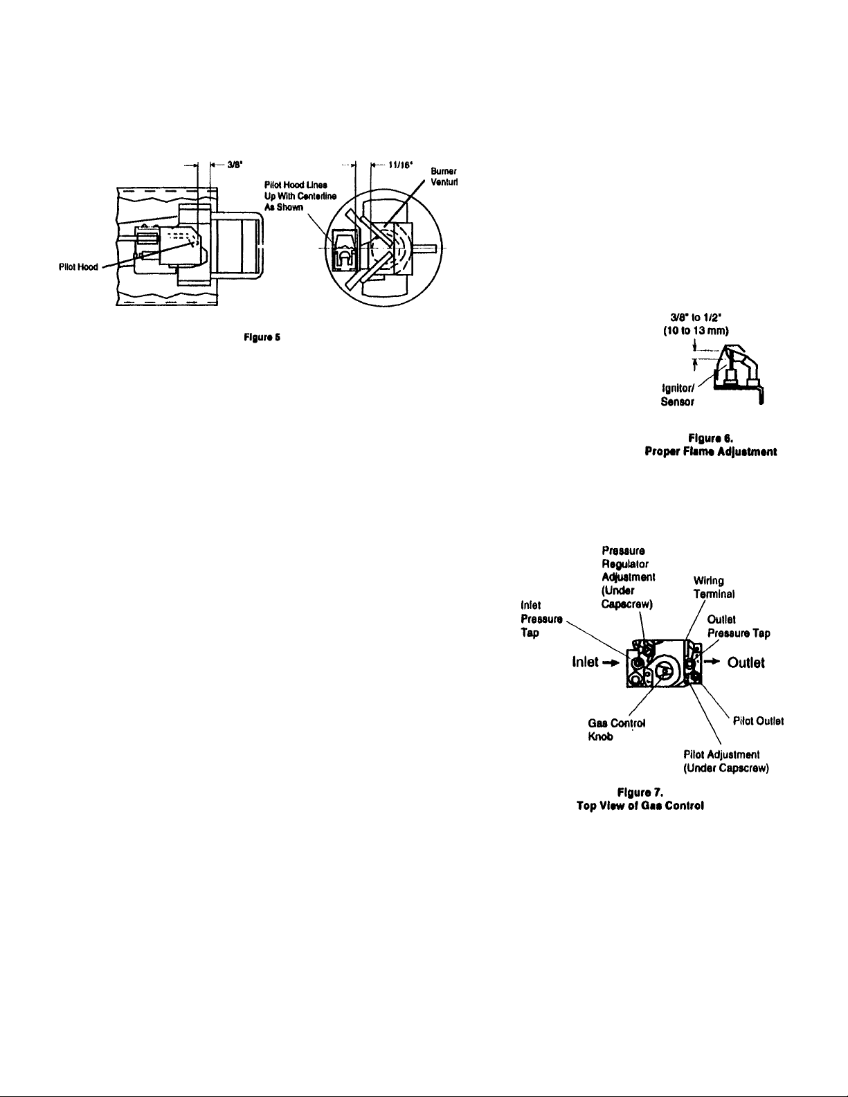
MANIFOLD REINSTALLATION
1. Verify the pilot ignitor/main burner venturi relationship using Figure 5.
2. Insert the venturt assembly Into the burner tube.
3. Fasten the four venturi mounting plate screws. Refer to Figure 1.
4. Fasten the gas pipe union. Refer to Figure 1.
5. Turn on the electrical power supply to the oven.
6. Turn on the gas supply at the service valve behind the oven.
ADJUST THE PILOT BURNER FLAME
The pilot flame should envelop 3/8 to 1/2 Inch (10 to 13 millimeters) of the lgnitor-sensor dp. Refer to Figure 6. II necessary
adjust the pilot flame;
1. Remove the pilot adjustment cover screw of the gas control. Refer to Figure 7.
2. Turn the Inner adjustment screw clockwise to decrease or counterclockwise to Increase the pilot flame.
3. Always replace the cover screw after adjustment and tighten firmly to ensure proper operation.
Shut off the gas supply at the service valve
behind the oven before removing the outlet
pressure lap plug or before disconnecting the manometer.
ADJUST MANIFOLD PRESSURE
1.The gas control outlet pressure should be 10.5' w.c. (or propane gas.
2. With the main burner operating, check the gas pressure using a manometer connected to the gas
control outlet pressure tap. Refer to Figure 7.
3. If necessary, adjust the pressure regulator:
a. Remove the pressure regulator adjustment cap and screw.
b. Using a screwdriver, turn the Inner adjustment screw clockwise to Increase or counterclockwise
to decrease the main burner gas pressure.
c. Always replace the cap screw and tighten firmly to ensure proper operation.
4. If the desired outlet gas pressure cannot be achieved by adjusting the gas control, check the gas
control Inlet pressure using a manometer at the Inlet
pressure tap. If the Inlet pressure Is at least 11'w.c. (or propane, replace the gas control. Otherwise,
take the necessary steps to provide proper gas pressure to the gas control.
5. Be sure the main burner primary air supply Is properly adjusted (or complete combustion
(approximately 1/4' to 3/8' open).
6. Perform gas leak test.
FIRE OR EXPLOSION HAZARD CAN CAUSE PROPERTY DAMAGE.
SEVERE INJURY OR DEATH. Check for gas leaks with rich soap and water
solution any time work Is done on a gas system.
GAS LEAK TEST
1. Paint all pipe connections from the gas union to the venturi mounting plate Including the bypass and pilot tube connections and pressure tap plugs with a rich soap
and water solution. Bubbles Indicate a gas leak.
2. If a gas leak Is detected, tighten the pipe connection.
3. Stand clear while lighting main burner to prevent Injury caused from hidden gas leaks which could cause flashback In the machinery compartment. Light the main
burner.
4. With the main burner In operation, paint all pipe joints with rich soap and water solution.
5. If another gas leak Is detected, tighten joints and pipe connections,
6. Replace the part If gas leak cannot be slopped.
Page 99
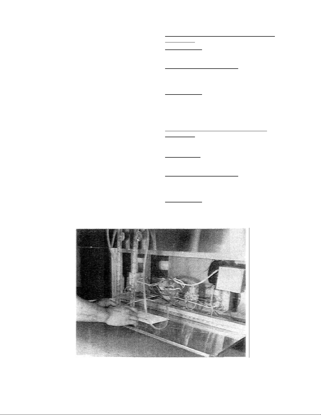
X. PIPE SIZING - Always install a shutoff valve in the
gas supply line to the oven (supplied with PS200
ovens). This valve should be the same size as the
supply line and should have a full minimum 3/4" throat
opening..
The minimum incoming line flow pressure (when oven
is on high flame cycle) should be the following:
Natural Gas -6" W.C.
Propane Gas -11" W.C.
This pressure reading can be taken by installing a gas
pressure gauge on the left hand side of the main gas
valve. Outgoing pressure can be measured at the tap
at the right hand side of the main gas valve. (See
Figure 53).
SECTION 2 SERVICING
COMPONENTS
RECOMMENDED SUPPLY PIPE SIZE FOR
NATURAL GAS OVENS AT 6" W.C. INCOMING
PRESSURE.
All single ovens: PS200/310/360
1 -1 /2" (38 mm) on runs up to
200 feet (61 m)
Double ovens or Single Tandem:
PS200/310/360
2" (51 mm) on runs up to
200 feet (61 m)
Double Tandem: PS200/310/360
2-1/2" (63 mm) on runs up to
200 feet (61 m)
For runs over 200 feet (61 m) consult factory.
NOTE: Gas pressure should always be set when the
burner is in the low flame mode. If pressure drops
when oven goes to high flame, it is an indication of a
gas supply problem.
Natural Gas -3.5" W.C.
Propane Gas -11" W.C.
Please remember that the longer the pipe runs, the
more the pressure drops. One 90° elbow equals a 4
foot length of pipe.
Refer to pipe sizing chart to determine what size gas
pipe to run to the oven.
NOTE: The PS310/360 is rated for 135.000 BTU/hr for
each oven cavity. A double oven would use 270,000
BTU/hr.
The PS200 is rated for 120,000 BTU/hr for each oven
cavity. A double oven would use 240,000 BTU/hr
RECOMMENDED SUPPLY PIPE SIZE FOR
PROPANE OVENS AT 12" W.C. INCOMING
PRESSURE.
Have owner inform Propane supplier of the following
oven requirements and have them size accordingly:
All single ovens: PS200/310/360
1" (25 mm) on runs up to
200 feet (61 m)
Double ovens or Single Tandem:
PS200/310/360
1 -1/2" (38 mm) on runs up to
200 feet (61 m)
Double Tandem: PS200/310/360
2" (51 mm) on runs up to
200 feet (61 m)
For runs over 200 feet (61 m) consult factory.
Figure 53. Checking PS310/360 Incoming and Outgoing
Pressure with 2 Water Column Gauges
61
Page 100
SECTION2
SEVICING COMPONENTS
Figure 54. Checking PS200 Incoming and
Outgoing Pressure with 2 Water Column
Gauges
62
 Loading...