

Middle Atlantic Products VDM, VDM-600-F, VDM-400-T, VDM-400-F, VDM-600-T Instruction Sheet
Instruction Sheet
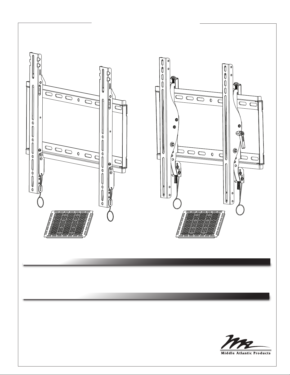
VDM Series
FIXED & TILT WALL MOUNT
VDM-400-F & VDM-600-F
THANK YOU
Thank you for purchasing a Vision Display fixed or tilt wall mount.
Please read these instructions thoroughly before installing or assembling these products.
PRODUCT FEATURES
• Open wall plate design maximizes accessibility to connections and cable pass-through behind
the display
• Post-install leveling mechanism enables quick micro-adjustment of horizontal plane of display
• Safety locking features keep the display securely mounted
• VESA Capability:
VDM-400-F & VDM-400-T 75x75mm - 400x400mm
VDM-600-T & VDM-600-T 75x75mm - 600x400mm
VDM-400-T & VDM-600-T
I-00807 Rev A
IMPORTANT SAFETY INSTRUCTIONS / INSTRUCTIONS IMPORTAANTES SUR LA SÉCURITÉ
SAVE ALL INSTRUCTIONS / CONSERVER CES INSTRUCTIONS
WARNING/AVERTISSEMENT and the exclamation point within an
equilateral triangle is intended to alert the user to the possibility of
serious injury or death if the instructions are not followed.
Avertissement et le point d'exclamation dans un triangle équilatéral
est destiné à alerter l'utilisateur de la possibilité de blessures
graves ou la mort si les instructions ne sont pas suivies.
CAUTION/ATTENTION and the exclamation point within an
equilateral triangle is intended to alert the user to the possibility of
damaging or destroying the equipment if the instructions are not
followed.
Attention et le point d'exclamation dans un triangle équilatéral est
destiné à alerter l'utilisateur de la possibilité d'endommager ou de
détruire l'équipement si les instructions ne sont pas suivies.
WARNING: Failure to read, understand and follow the following information can result in serious personal injury, damage to the equipment or voiding of the warranty.
AVERTISSEMENT: Ne pas lire, comprendre et suivre les informations suivantes peut entraîner
des blessures graves, des dommages à l'équipement ou de la nullité de la garantie.
WARNING: Failure to provide correct structural strength for the component may result in serious personal injury or damage the equipment. The 2x4 stud wall to which the component is
being attached may have a maximum drywall thickness of 5/8” (1.6 cm).
AVERTISSEMENT: Le défaut de fournir une résistance structurelle correcte pour le composant
peut entraîner des blessures graves ou endommager l'équipement. Le goujon de 2x4 auquel le
composant mur est connecté peut avoir un maximum de 1.6 cm (5/8”) d'Épaisseur cloison
sèche.
WARNING: Exceeding the weight capacity may result in personal injury or equipment damage.
The combined weight of all components attached to the mount must not exceed weights listed
on page 3.
AVERTISSEMENT: Dépasser la capacité de poids peut entraîner des blessures ou des dommages matériels. Le poids combiné de tous les composants reliés au support de montage ne
doit pas dépasser les grammages indiqués à la page 3.
WARNING: Be aware of pinch points and do not place fingers in between moving parts.
AVERTISSEMENT: Soyez conscient des points de pincement et de ne pas placer les doigts
entre les pièces mobiles.
WARNING: Use this product for its intended use and only use attachments recommended by
the manufacturer.
AVERTISSEMENT: Utilisez ce produit pour son utilisation prévue et utiliser uniquement les
accessoires recommandés par le fabricant.
WARNING: Do not use a damaged product. Return damaged products to a qualified service
center for repair.
AVERTISSEMENT: Ne pas utiliser un produit endommagé. Retour produits endommagés à un
centre de service qualifié pour la réparation.
WARNING: Not intended for outdoor use.
AVERTISSEMENT: Non destiné à une utilisation en extérieur.
Page 2
WEIGHT RATINGS
Model Weight Rating
VDM-400-F 150 lbs. Maximum Total Rated Load
VDM-400-T 150 lbs. Maximum Total Rated Load
VDM-600-F 180 lbs. Maximum Total Rated Load
VDM-600-T 180 lbs. Maximum Total Rated Load
TOOLS REQUIRED
• #2 Phillips Screwdriver
• Drill
• Protective Eyewear
• 7/32” Wood Bit or 7/16“ Masonary Bit
• Level
• Hammer
• 1/2” Hex Socket
WARNING: Use tools with caution and follow all necessary safety protocols.
AVERTISSEMENT: Utiliser des outils avec prudence et suivre tous les protocoles de sécurité
nécessaires.
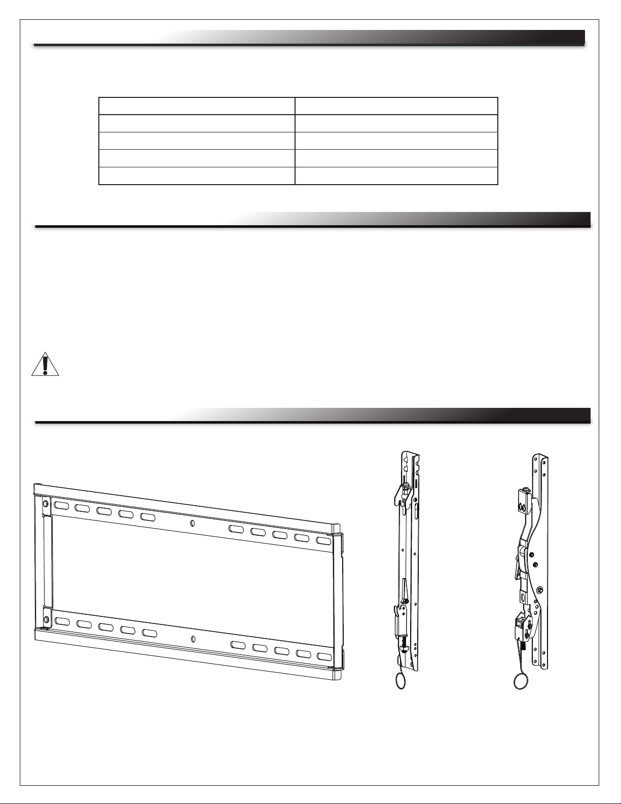
SUPPLIED COMPONENTS
(1)
Wall Mount Bracket
(A)
Page 3
(2)
Fixed Display
Mount Brackets
VDM-400 & -600-F
MODELS ONLY
(B)
(2)
Tilt Display
Mount Brackets
VDM-400 & -600-T
MODELS ONLY
(C)
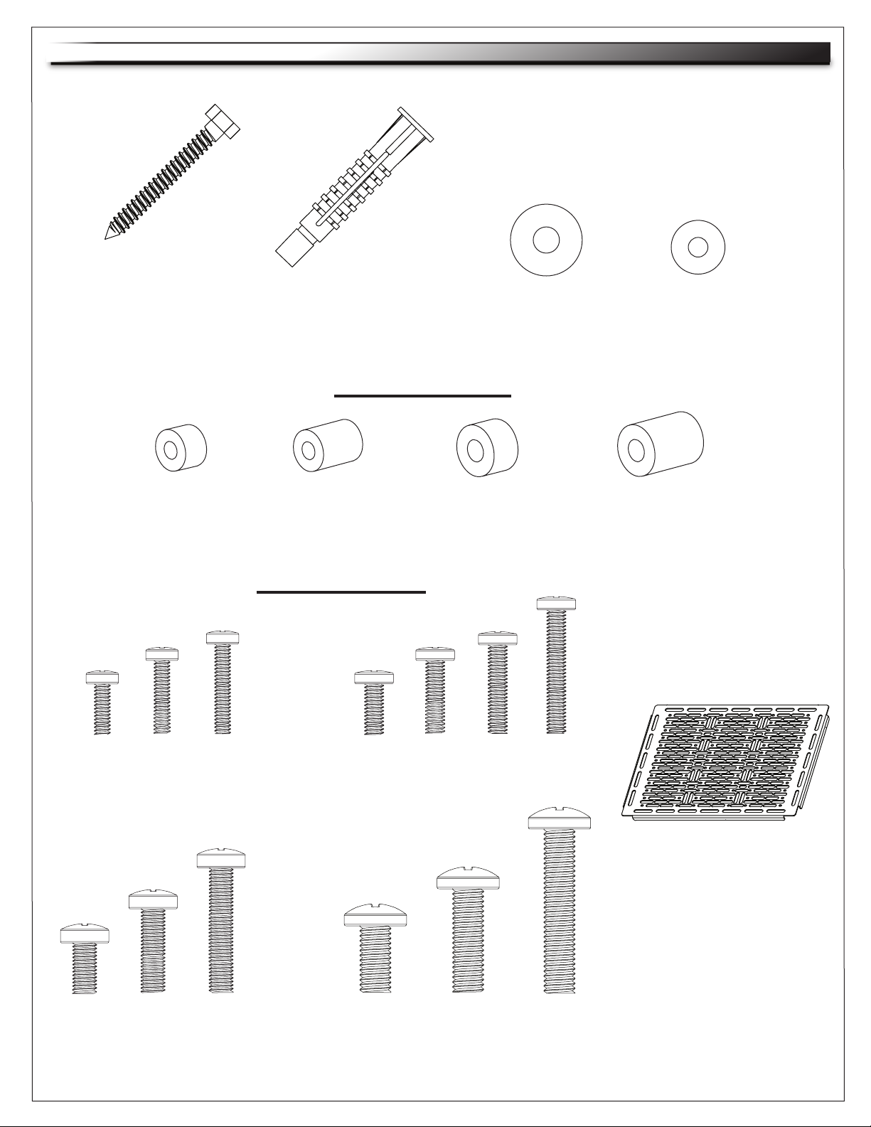
COMPONENTS SUPPLIED (CONTINUED)
(4)
Hex Head Screw
(D)
(4)
M6 Short Spacer
(H)
(4)
Wall Anchor
(E)
Display Mount Spacers
(4)
M6 Long Spacer
(J)
Display Mount Screws
(12)
M8 Washer
(4)
M8 Short Spacer
(K)
(F)
(4)
M5 Washer
(G)
(4)
M8 Long Spacer
(L)
(4)
M4 x 12
(M-A)
(4)
M6 x 12
(M-H)
(4)
M4 x 16
(M-B)
(4) (4)
M6 x 20
(M-J)
(4)
M4 x 20
(M-C)
M6 x 30
(M-K)
(4)
M5 x 12
(M-D)
(4)
M8 x 16
(M-L)
(4)
M5 x 16
(M-E)
M8 x 20
Page 4
M5 x 20
(4)
(M-M)
(4)
(M-F)
(4)
M5 x 30
(M-G)
(1)
Proximity Mounting
Plate Kit
(P)
(4)
M8 x 40
(M-N)

WOOD STUD WALL BRACKET INSTALLATION
1. Determine height for display and find center of stud closest to desired position on wall. Locate the center of
the second stud to the left or right of desired location.
2. Using a level, scribe a 10” long line down the center of both studs at the desired height. (FIGURE A)
FIGURE A
3. Using a level and the wall mount bracket (A) as a template, mark the center of the 4 mounting holes in line
with the scribed center line of each stud. (FIGURE B)
Mounting slots
A
FIGURE B
4. Remove wall mount bracket and using a 7/32” drill bit, drill a 2.5” deep pilot hole in each of the 4 marked
center points.
Page 5
 Loading...