

Middle Atlantic Products 1000R, UPS-1000R-IP, UPS-1000R-8IP, 2200R, UPS-2200R User Manual
...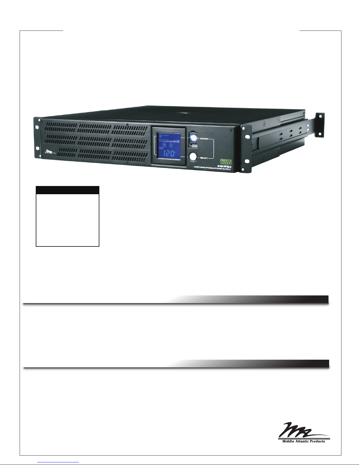
USER MANUAL
1000R and 2200R Series
Rackmounted Uninteruptible Power Supply
MODEL NUMBERS
• UPS-1000R
• UPS-1000R-IP
• UPS-1000R-8IP
• UPS-2200R
• UPS-2200R-IP
• UPS-2200R-8IP
THANK YOU
Thank you for purchasing the 1000R or 2200R Series Rackmounted UPS. The UPS provides battery
backup during power outages, automatic voltage regulation during periods of inconsistent utility power
and surge protection.
IMPORTANT
Please read this manual before removing the UPS from the shipping carton and before making any
connections to and operating your UPS.
I-00319 Rev N

TABLE OF CONTENTS
Important Safety Instructions . . . . . . . . . . . . . . . . . . . . . . . . . . . . . . . . . . . . . . . . 3 - 4
Middle Atlantic Products Green Power UPS Technology . . . . . . . . . . . . . . . . . . . . . 5
FCC Warning . . . . . . . . . . . . . . . . . . . . . . . . . . . . . . . . . . . . . . . . . . . . . . . . . . . . 5 - 6
Circuit Diagram . . . . . . . . . . . . . . . . . . . . . . . . . . . . . . . . . . . . . . . . . . . . . . . . . . . . 6
Unpacking and Parts List . . . . . . . . . . . . . . . . . . . . . . . . . . . . . . . . . . . . . . . . . . . . 7
Installation and Mounting . . . . . . . . . . . . . . . . . . . . . . . . . . . . . . . . . . . . . . . . . . . 7 - 8
Front Panel Descriptions . . . . . . . . . . . . . . . . . . . . . . . . . . . . . . . . . . . . . . . . . . . . . 9
Rear Panel Descriptions (Bank Outlets) . . . . . . . . . . . . . . . . . . . . . . . . . . . . . . . 9 - 10
Rear Panel Descriptions (Individual Outlets) . . . . . . . . . . . . . . . . . . . . . . . . . . . 11 - 12
Setup Of (NIC) UPS-IPCARD . . . . . . . . . . . . . . . . . . . . . . . . . . . . . . . . . . . . . . 13 - 15
LCD Display Definitions . . . . . . . . . . . . . . . . . . . . . . . . . . . . . . . . . . . . . . . . . . . . 16
Battery Charging . . . . . . . . . . . . . . . . . . . . . . . . . . . . . . . . . . . . . . . . . . . . . . . . . . 17
Self Test . . . . . . . . . . . . . . . . . . . . . . . . . . . . . . . . . . . . . . . . . . . . . . . . . . . . . . . . . 17
EPO (Emergency Power Off) Port Connection . . . . . . . . . . . . . . . . . . . . . . . . . . . 17
Operation . . . . . . . . . . . . . . . . . . . . . . . . . . . . . . . . . . . . . . . . . . . . . . . . . . . . . . . . 18
General Status Mode . . . . . . . . . . . . . . . . . . . . . . . . . . . . . . . . . . . . . . . . . . . . . . . 19
Functions Setup Mode . . . . . . . . . . . . . . . . . . . . . . . . . . . . . . . . . . . . . . . . . . . 19 - 20
Battery Replacement . . . . . . . . . . . . . . . . . . . . . . . . . . . . . . . . . . . . . . . . . . . . 21 - 24
Optional External Battery Connection . . . . . . . . . . . . . . . . . . . . . . . . . . . . . . . . . . 24
Troubleshooting . . . . . . . . . . . . . . . . . . . . . . . . . . . . . . . . . . . . . . . . . . . . . . . . 25 - 26
Technical Specifications . . . . . . . . . . . . . . . . . . . . . . . . . . . . . . . . . . . . . . . . . . 27 - 28
Estimated Runtime . . . . . . . . . . . . . . . . . . . . . . . . . . . . . . . . . . . . . . . . . . . . . . 28 - 29
Warranty . . . . . . . . . . . . . . . . . . . . . . . . . . . . . . . . . . . . . . . . . . . . . . . . . . . . . . . . . 29
Warranty Registration . . . . . . . . . . . . . . . . . . . . . . . . . . . . . . . . . . . . . . . . . . . . . . . 30
Page 2
IMPORTANT SAFETY INSTRUCTIONS
READ AND SAVE THESE INSTRUCTIONS
This manual contains important instructions that should
be followed during installation and maintenance of the
UPS and batteries.
The lightning flash with the arrowhead symbol, within an equilateral triangle, is intended to alert the user
to the presence of uninsulated dangerous voltage within the product’s enclosure that may be of sufficient
magnitude to constitute a risk of electric shock.
The exclamation point within an equilateral triangle is intended to alert the user to the presence of
important operating and maintenance (servicing) instructions in the literature accompanying the product.
WARNING:
The UPS must be connected to a grounded AC power outlet with fuse or circuit breaker
protection. DO NOT plug the UPS into an outlet that is not grounded. If you need to de-energize this
equipment, turn off and unplug the UPS.
WARNING:
The internal battery in this UPS is always charged. The battery can energize hazardous live
parts inside the unit, even when the AC input power is disconnected.
WARNING:
To prevent the risk of fire or electric shock, install in a temperature and humidity controlled
indoor area, free of conductive contaminants. (Please see specifications for acceptable temperature and
humidity range).
WARNING:
To reduce the risk of electric shock, do not remove the cover, except to service the battery.
There are no serviceable parts inside, except for the battery.
WARNING:
servicing the battery or installing a component
WARNING:
affect operation or safety of any life support equipment, with any medical applications, or patient care
WARNING: Risk of battery explosion, if battery is replaced by an incorrect type or rating.
WARNING: Do not open or mutilate the batteries. Electrolyte is harmful to the skin and eyes and may be
toxic.
To avoid electric shock, turn off the unit and unplug it from the AC power before
.
Do not use for medical or life support equipment. Do not use in any circumstance that would
.
WARNING: A battery can present a high risk of short circuit current or electrical shock.
WARNING: The battery may present the risk of electrical shock. Do not dispose of batteries in a fire, as
they may explode. Follow all local ordinances regarding proper disposal of batteries.
CAUTION: Risk of energy hazard, 12V, 9AH battery. Before replacing batteries, remove conductive jewelry
such as chains, wrist watches, and rings. High energy through conductive materials could cause severe
burns.
CAUTION: To reduce the risk of fire, connect only to a circuit provided with 20 Amperes maximum branch
overcurrent protection in accordance with the National Electrical Code, ANDI/NFPA 70.
CAUTION: Use only the specified type of battery. See your dealer for replacement batteries.
CAUTION: For PLUGGABLE EQUIPMENT, the socket-outlet shall be installed near the equipment
Page 3
CONSIGNES DE SÉCURITÉ IMPORTANTES
LIRE ET CONSERVER CES INSTRUCTIONS
Ce manuel contient des instructions importantes à suivre
lors de l'installation et de la maintenance de l'onduleur et
des batteries.
L'éclair avec le symbole de flèche dans un triangle équilatéral est destiné à alerter l'utilisateur de la présence
d'une tension dangereuse non isolée dans l'enceinte du produit qui peut être d'une ampleur suffisante pour
constituer un risque de choc électrique pour les personnes
Le point d'exclamation dans un triangle équilatéral est destiné à alerter l'utilisateur de la présence
d'importants instructions d’opération et de maintenance (entretien) dans la documentation accompagnant
l'appareil
AVERTISSEMENT: L’onduleur doit être branché sur une prise de courant alternatif protégée par un fusible
ou un disjoncteur. Ne branchez pas le UPS dans une prise qui ne sont pas mis à la terre. Si vous avez
besoin de mettre hors tension de cet équipement, éteindre et de débrancher l'onduleur.
AVERTISSEMENT: Même lorsque le cordon d’alimentation est débranché, les parties internes peuvent
recevoir suffisamment de courant de la batterie pour être dangereuses.
AVERTISSEMENT: Pour éviter les risque d'incendie ou de choc électrique, l’appareil doit être installé dans
un local libre de contaminants conducteurs et dont la température et l’humidité sont contrôlées
(reportez-vous aux spécifications techniques pour pren dre connaissance des plages de température et
d’humidité acceptables).
AVERTISSEMENT: Pour réduire le risque de choc électrique, ne pas enlever le couvercle, à l'exception de
réparer la batterie. Il n'y a pas de pièces réparables par l'intérieur, sauf pour la batterie.
AVERTISSEMENT: Pour éviter la décharge électrique, éteignez arrêtez l’unité et débranchez-la de la source
decourant alternatif avant d’entretenir la batterie.
AVERTISSEMENT: Ne pas utiliser pour l'équipement de soutien médical ou de la vie. Ne pas utiliser en
toute circonstance susceptible d'affecter fonctionnement ou la sécurité de tout le matériel de soutien de la
vie, avec toutes les applications médicales ou les soins aux patients.
AVERTISSEMENT: Risque d'explosion de la batterie, si la batterie est remplacée par un type incorrect ou
d'une qualification.
AVERTISSEMENT: N’ouvrez pas ou ne mutilez pas les batteries. Le matériel libéré est nocif à la peau et aux
yeux et peut être toxique.
AVERTISSEMENT: Une batterie peut présenter un risque élevé de courant de court-circuit ou un choc
électrique.
AVERTISSEMENT: La batterie peut présenter un risque de choc électrique. Ne jetez pas les batteries au
feu, car elles peuvent exploser. Suivez tous les règlements locaux concernant l'élimination adéquate des
piles.
ATTENTION: Risque de danger énergétique, batterie 12V, 9AH. Avant de remplacer les piles, retirez les
bijoux conducteurs tels que les chaînes, les montres-bracelets et les bagues. Une énergie élevée à travers
des matériaux conducteurs peut provoquer de graves brûlures.
ATTENTION: Pour réduire le risque d'incendie, relie seulement à un circuit équipé de 20 ampères de
branche de circuit de protection maximum de surintensité selon le code électrique national, ANSI/NFPA 70.
ATTENTION: Utilisez uniquement le type de pile spécifié. Voir votre concessionnaire pour les batteries
de remplacement.
ATTENTION: Pour les appareils raccordés, la prise de courant doit être installée près de l'équipement
et doit être facilement accessible.
Page 4

MIDDLE ATLANTIC PRODUCTS GREEN POWER UPS TECHNOLOGY
Our new UPS circuit is designed to save energy operating in
Green Power Bypass Mode.
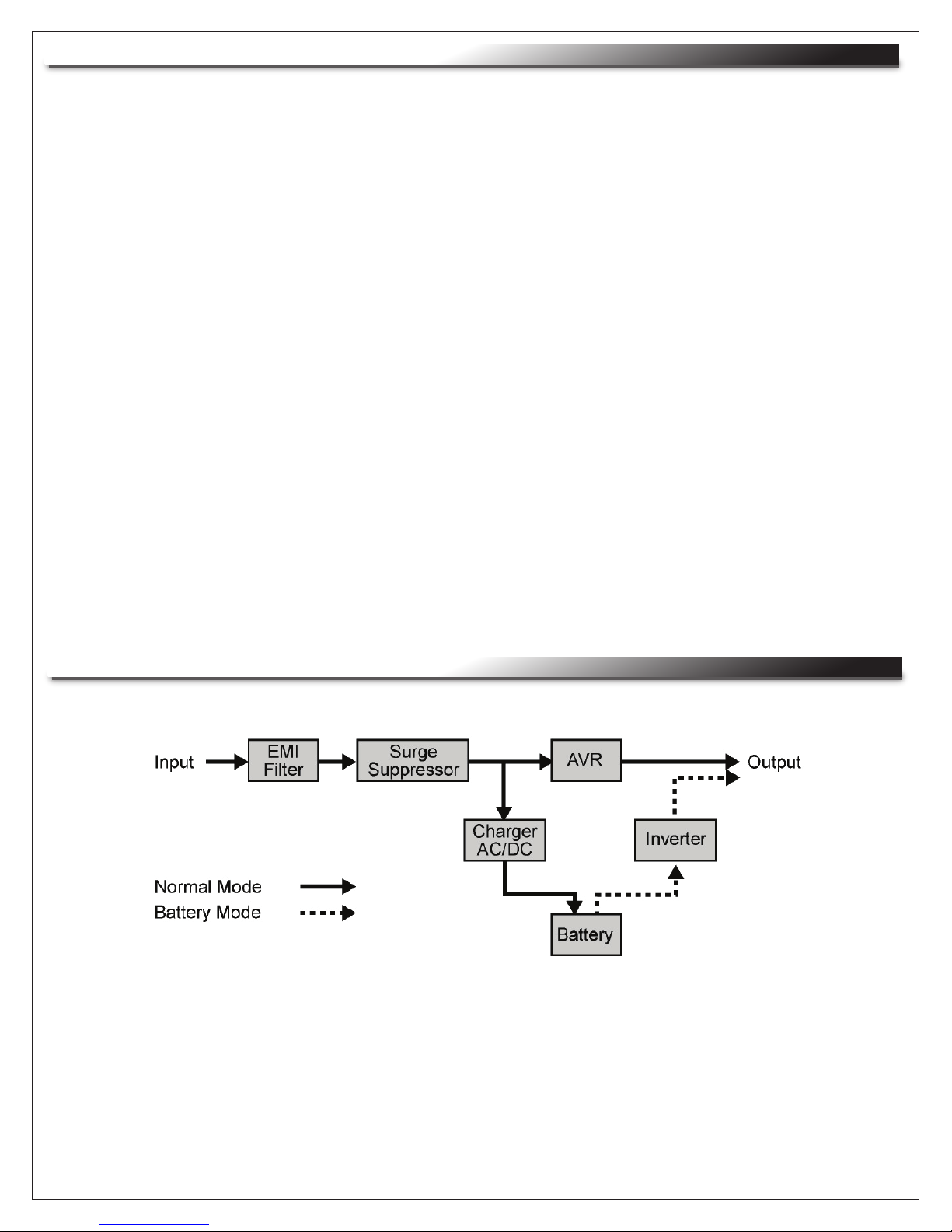
A traditional UPS circuit with Automatic Voltage Regulation (AVR) provides normal
output voltage through the relay and AVR transformer. The current travels first through the transformer
conducting energy and generating heat. This heat creates energy dissipation resulting in a “Power Loss”
or consumption of utility power and money.
Middle Atlantic Product's Green Power circuit design is a solution to this "Power Loss". When the utility
power is operating normally, our Green Power UPS works in Bypass Mode. Our Green Power design
conducts power only through the relay and still provides normal output voltage. Bypassing the
transformer reduces power consumption thereby conserving energy and saving money. When the utility
power is abnormal the UPS will operate under Battery or AVR Mode. Under this condition, Green Power
UPS and a traditional UPS would operate about the same. On average, utility power operates 88% of
the time and the Middle Atlantic Products Green Power Technology will work in its money/energy saving
Bypass Mode.
FCC WARNING
NOTE: This equipment has been tested and found to comply with the limits for a Class B digital device,
pursuant to Part 15 of the FCC Rules. These limits are designed to provide reasonable protection against
harmful interference in a residential installation. This equipment generates, uses and can radiate radio
frequency energy and, if not installed and used in accordance with the instructions, may cause
harmful interference to radio communications. However, there is no guarantee that interference will not
occur in a particular installation. If this equipment does cause harmful interference to radio or television
reception, which can be determined by turning the equipment off and on, the user is encouraged to try to
correct the interference by one or more of the following measures:
1. Reorient or relocate the receiving antenna.
2. Increase the separation between the equipment and receiver.
3. Connect the equipment into an outlet on a circuit different from that to which the receiver is connected.
4. Consult the dealer or an experienced radio/TV technician for help.
WARNING: A shielded-type power cord is required in order to meet FCC emission limits and also to
prevent interference to the nearby radio and television reception. It is essential that only the supplied
power cord be used. Use only shielded cables to connect I/O devices to this equipment.
WARNING: Any changes or modifications not expressly approved by the guarantee of this device
could void the user’s authority to operate the equipment.
Page 5
FCC WARNING (CONTINUED)
REMARQUE: Cet appareil a subi des tests de contrôle et a été déclaré conforme aux limites imposées
aux appareils numériques de Classe B par la section 15 de la réglementation FCC. Ces limites ont été
établies pour assurer une protection raisonnable contre les interférences indésirables lorsque l’appareil
fonctionne dans un environnement résidentiel. Cet appareil génère, exploite et peut émettre un
rayonnement de fréquence radio. En outre, en cas d’installation et d’utilisation non conforme aux
instructions, il risque de provoquer des interférences indésirables avec les transmissions radio.
Rien ne garantit qu’aucune interférence ne se produira dans une installation donnée. Si l’utilisation
de cet appareil provoque des interférences indésirables avec la réception radio ou télévision (ce que
vous pouvez déterminer en l’éteignant, puis en le rallumant), il est recommandé d’essayer d’y remédier
en prenant une ou plusieurs des mesures suivantes :
1. Réorientez ou déplacez l’antenne de réception.
2. Augmentez la distance entre l’appareil et le récepteur.
3. Branchez l’appareil sur une prise de courant située sur un circuit différent de celui du récepteur.
4. Contactez votre détaillant ou un technicien qualifié en réparation radio/télévision. Si un accessoire
spécifique est nécessaire pour assurer la conformité de l’appareil, cela doit être précisé dans les
instructions.
ATTENTION: Un cordon d’alimentation blindé est nécessaire pour respecter les limites d’émission
fixées par la FCC et pour empêcher les interférences avec les récepteurs radio ou télévision placés à
proximité. Il est impératif de n’utiliser que le cordon d’alimentation fourni. Ne connectez de périphériques
d’entrée/sortie à cet appareil qu’avec des câbles blindés.
ATTENTION: Toute modification apportée à ce produit qui n’est pas expressément approuvée par la
garantie peut priver l’utilisateur de son droit d’utiliser l’appareil.
CIRCUIT DIAGRAM
Page 6
UNPACKING AND PARTS LIST
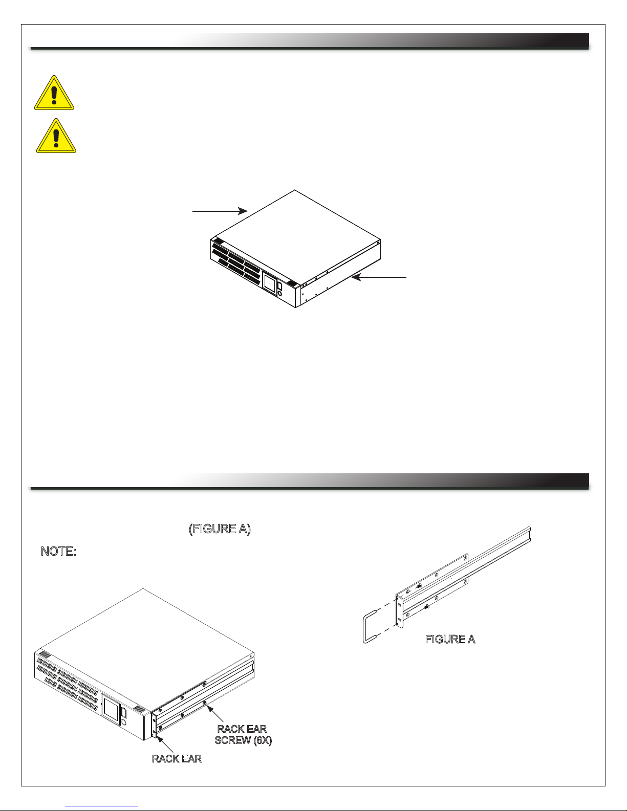
CAUTION: DO NOT LIFT THE UPS WHILE HOLDING THE FRONT FACE OF THE UNIT.
THIS MAY DAMAGE THE UNIT. ALWAYS LIFT THE UPS BY HOLDING IT BY BOTH SIDES.
ATTENTION: NE SOULEVEZ PAS L'UPS PAR LE FRONT DE L'UNITÉ COMME CELA PEUT
ENTRAÎNER DOMMAGES. TOUJOURS SOULEVER UNITÉ DES DEUX CÔTÉS.
LIFT OUT OF BOX
WHILE HOLDING
BOTH SIDES OF
UPS
LIFT OUT OF BOX
WHILE HOLDING
BOTH SIDES OF
UPS
The UPS is very heavy and should be handled by two (2) people. After the product is removed from its
shipping carton, inspect the UPS before installing and operating. The shipping carton should contain the
following items:
(1) UPS unit; (1) User’s Manual; (2) Rack ears; (14) 10-32 Rack ear screws; (8) Nylon rivets (Used to
plug four front screw holes for mounting ears if the unit will not be rack mounted);
(1) Telephone Cable (black); (2) Rackmount handles; (4) 8-32 Rackmount handle screws;
(1) Emergency Power Off Cable (gray); (1) Middle Atlantic Power Manager Software CD;
(2) Serial Interface Cable (DB-9); (1) USB cable; (1) Warranty Registration Card
INSTALLATION AND MOUNTING
1) If using the provided handles install them now
using provided 8-32 screws. (FIGURE A)
NOTE:
The handles cannot be installed
after the unit is rack-mounted.
FIGURE A
RACK EAR
2) Install ears as shown using provided 10-32 screws.
Six screws per ear, one ear per side.
RACK EAR
SCREW (6X)
Page 7

INSTALLATION AND MOUNTING (CONTINUED)
CAUTION: THIS UNIT IS HEAVY, LIFT CAREFULLY
ATTENTION: CET APPAREIL EST LOURD,
SOULEVEZ AVEC ATTENTION
One Person Installation:
1) Determine mounting location.
2) Install the Rear Mounting Brackets as shown. One Bracket is longer then the other to provide guidance
when doing a one person installation. These brackets are interchangeable. (FIGURE A)
IMPORTANT NOTE: Rear Mounting Brackets mount between the two corresponding rackspaces in the front
of the enclosure. (FIGURE B)
3) Carefully lift the unit to the mounting position constantly supporting the bottom. Place the slide on the
unit’s ear onto the longer Rear Mounting Bracket then guide the unit onto the other Rear Mounting Bracket.
Once the ears and the Rear Mounting Brackets are fully engaged, slide to unit to the back of the enclosure.
4) Install the front of the unit to the rackrail. (FIGURE C)
FIGURE A
RACKSCREWS
(4X)
FIGURE B
FIGURE C
RACKSCREWS
(4X)
Two Person Installation:
1) Determine mounting location.
2) Properly support the unit from the bottom and carefully lift to the mounting location.
3) While adequately supporting the bottom, install the front of the unit to the rackrail. (FIGURE D)
4) Install the Rear Mounting Brackets as shown. Continue to support the bottom of the unit. (FIGURE E)
IMPORTANT NOTE: Rear Mounting Brackets mount between the two corresponding rackspaces in the front
of the enclosure. (FIGURE B)
RACKSCREWS
(4X)
FIGURE D FIGURE E
RACKSCREWS
(4X)
Page 8
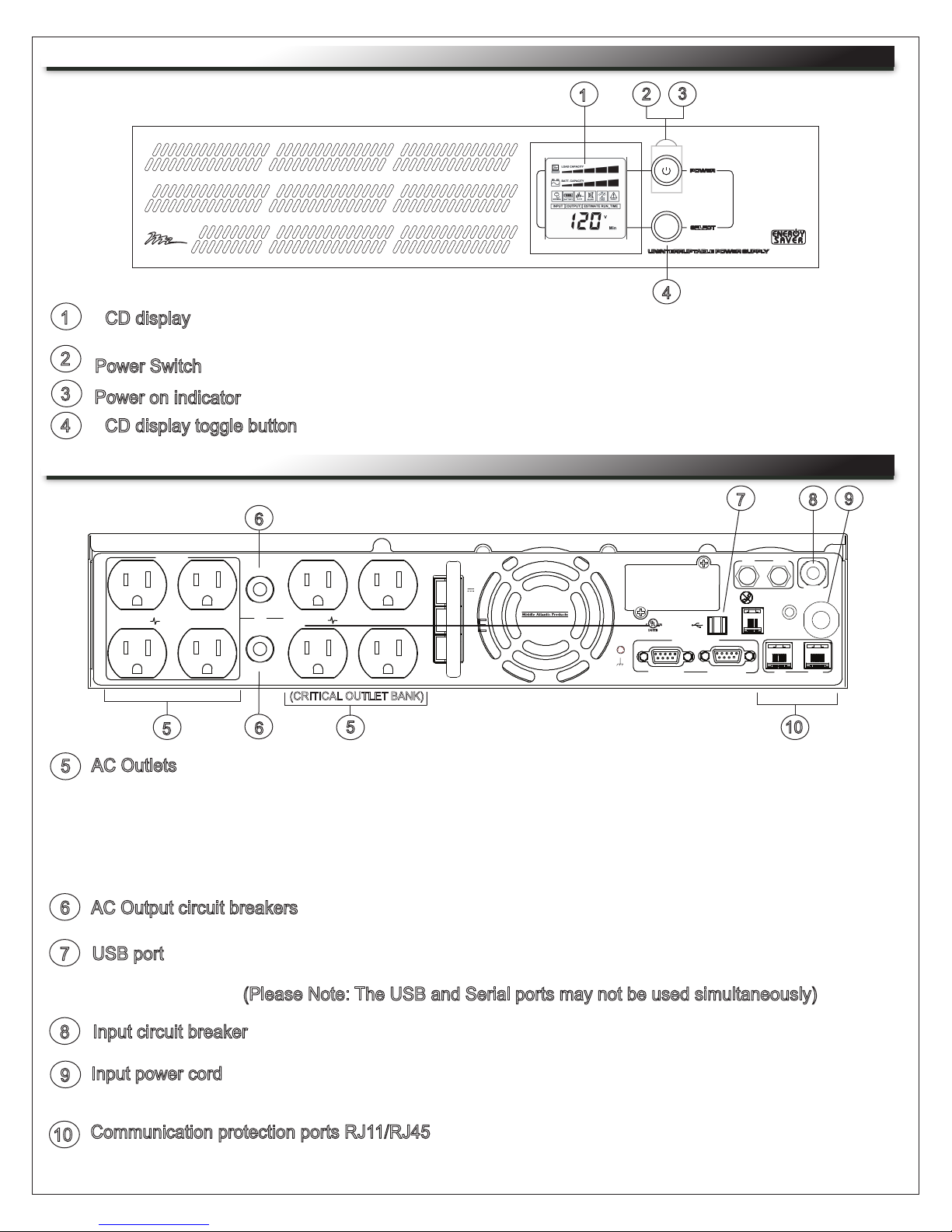
FRONT PANEL DESCRIPTIONS
1
LCD display: The LCD display indicates a variety of UPS operational conditions (see page 14 for LCD
display definitions).
2
Power Switch: On/off switch to turn UPS on and off.
3
Power on indicator
: Indicates the UPS is turned on.
3
1
2
4
LCD display toggle button
4
: Toggles between a variety of UPS operational conditions (see page 14).
REAR PANEL DESCRIPTIONS - BANK OUTLETS
6
Critical
Load
Surge
Protected
5
AC Outlets
5
Non-Critical
Load
Surge
Protected
5
Reset
125V
8A
60Hz
Reset
(CRITICAL OUTLET BANK)
6
: All AC outlets provide connected equipment with AC line power, surge protection and line
noise filtering during normal operation. Automatic voltage regulation corrects low voltage and
high voltage conditions without using battery power. All outlets provide battery power during blackouts
and severe brownout or severe high voltage conditions. The Non-Critical Load outlet bank can be
configured to automatically shut down during a power outage event providing longer up-time for
equipment plugged into the Critical Load outlet bank.
Input:
48V
Expansion Port
XXXX
Primary
Serial Port
Secondary
9
OUT
Reset
Wiring Fault
125V
12A
60Hz
750W
1000VA
D
A
T
A
IN OUT
8
7
IN
EPO
10
AC Output circuit breakers: Resettable circuit breakers provides AC output overload protection.
6
USB port
7
: Connects UPS to your computer via the supplied USB cable for UPS setup, configuration and
unattended shutdown in the event of a power failure. For use with the supplied Middle Atlantic Power
Manager software. (Please Note: The USB and Serial ports may not be used simultaneously)
Input circuit breaker
8
Input power cord: Heavy-duty permanently attached SignalSafe power cord, connects UPS to mains
9
: Resettable circuit breaker provides input overload protection.
power.
Communication protection ports RJ11/RJ45: Protects against surges on a single phone, fax, modem or
10
Ethernet network lines.
TM
Page 9
 Loading...