

Middle Atlantic Products T5 Instruction Sheet
Instruction Sheet
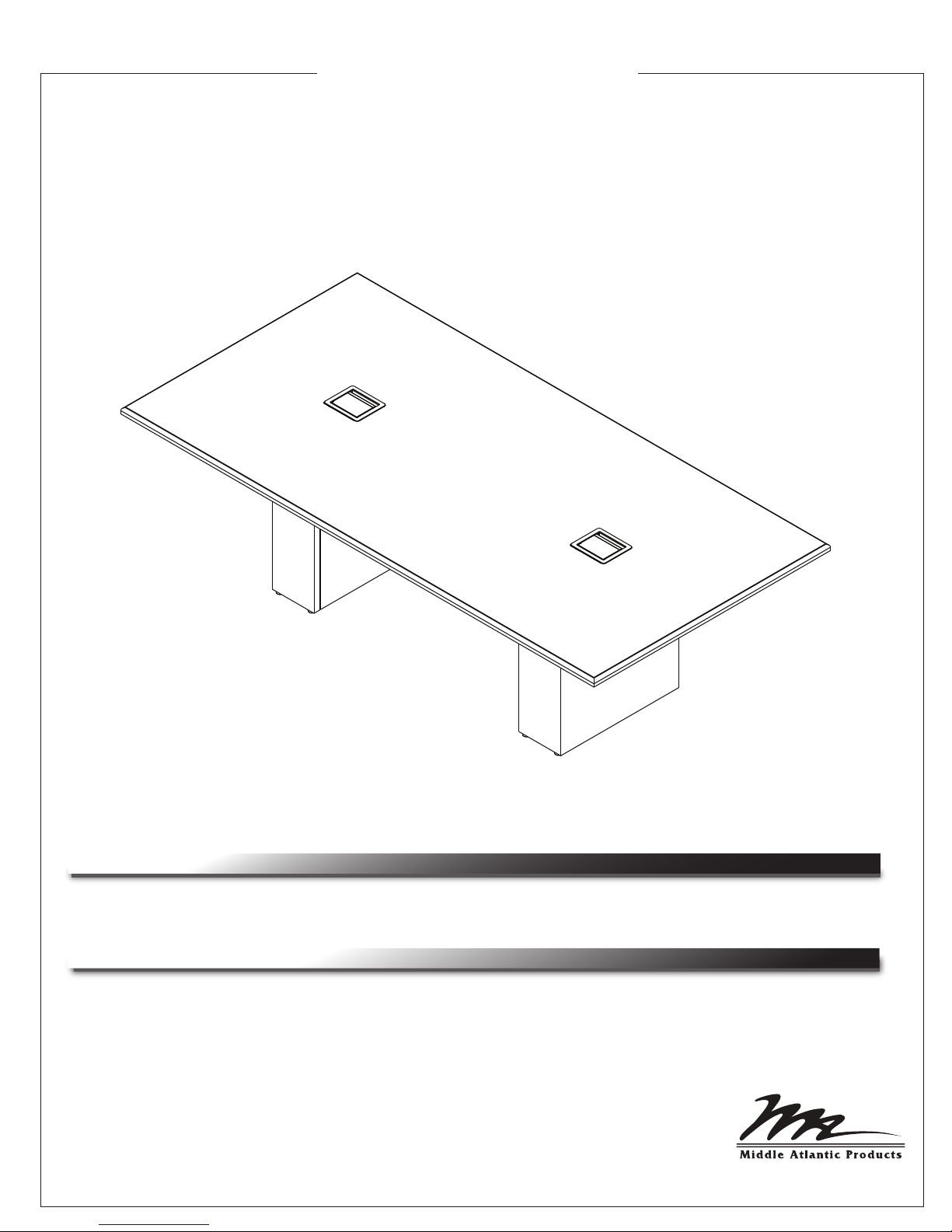
T5 SERIES
Pre-Select Conference Tables
THANK YOU
Thank you for purchasing a T5 Series Pre-Select Conference Table. Please read these
instructions thoroughly before installing or assembling this product.
PRODUCT FEATURES
• Patent-pending swing-out pedestal rack can be located in the table pedestal of choice.
Innovative flexibility for up to 3 RU of sideways rackmounting, small device mounting or a
combination of the two. Includes three tool-free Lever Lock™ plates for mounting small devices
• Wiremold InteGreat™ Table Boxes in black or silver with 2 retracting HDMI cables and 2 AC
outlets for power and connectivity at the surface. Table boxes and cable retractors are
concealed by the table’s pedestal
• Power distribution
• Cable management strips and bridge lances
I-00825 Rev -

IMPORTANT SAFETY INSTRUCTIONS
• Read these instructions.
• Keep these instructions.
DANGER HAZARDOUS VOLTAGE: The lightning flash with the arrowhead symbol, within an equilateral triangle is intended to alert the user to the
presence of uninsulated dangerous voltage within the product’s enclosure that may be of sufficient magnitude to constitute a risk of electric shock to
persons.
WARNING: A warning alerts you to a situation that could result in serious personal injury or death.
CAUTION: A caution alerts you to a situation that may result in minor personal injury or damage to the product and/or property.
NOTE: A note is used to highlight procedures pertaining to the installation, operation, or maintenance of the product.
WARNING: Failure to read, understand and follow the following information can result in serious personal injury, damage to the
equipment or voiding of the warranty. It is the responsibility of the Installer/User to ensure that this product is loaded according to
specifications.
WARNING: The weight ratings of this product can be found on the product. Exceeding these weight ratings can result in serious
injury or damage to the equipment. It is the responsibility of the Installer/User to ensure the components installed do not surpass the
weight ratings as an unstable condition can occur which may cause possible injury or damage.
CAUTION: If there is visible damage on the product, it must not be installed.
CAUTION: Safety measures must be practiced at all times during the assembly of this product. Use proper safety equipment and
tools for the assembly procedure to prevent personal injury.
• Heed all warnings.
• Follow all instructions.
• Clean only with dry cloth.
• Only use attachments/accessories specified by the manufacturer.
CAUTION: Note that during construction, there must be no possibility of personal injury, for example the squeezing of fingers or
arms.
CAUTION: For loading, always put heavier items at the bottom of the bays, not near the top, in order to help prevent the possibility
of the furnishing tipping over.
CAUTION: The appliance is not intended for use by young children or infirm persons without supervision.
Safety Instructions: Rack Mount
Elevated Operating Ambient: If installed in a closed or multi-unit rack assembly, the operating ambient temperature of the rack
environment may be greater than room ambient. Therefore, consideration should be given to installing the equipment in an environment
compatible with the maximum ambient temperature (Tma) specified by the manufacturer.
Reduced Air Flow: Installation of the equipment in a rack should be such that the amount of air flow required for safe operation of the
equipment is not compromised.
Mechanical Loading: Mounting of the equipment in the rack should be such that a hazardous condition is not achieved due to uneven
mechanical loading.
Circuit Overloading: Consideration should be given to the connection of the equipment to the supply circuit and the effect that
overloading of the circuit might have on overcurrent protection and supply wiring. Appropriate consideration of equipment nameplate
ratings should be used when addressing this concern.
Reliable Earthing: Reliable earthing of rack-mounting equipment should be maintained. Particular attention should be given to supply
connections other than direct connections to the branch circuit (e.g. use of power strips).
Disconnect Device (Pluggable Equipment): The socket-outlet shall be installed near the equipment and shall be easily accessible.
Page 2
INSTRUCTIONS IMPORTANTES SUR LA SÉCURITÉ
• Lire ces instructions.
• Conservez ces instructions.
DANGER TENSION DANGEREUSE: Le symbole de la pointe de flèche, dans un triangle équilatéral, est destiné à alerter l'utilisateur sur la
présence de tension dangereuse non isolée dans l'enceinte du produit qui peut être d'une ampleur suffisante pour constituer un risque d'électrocution.
AVERTISSEMENT: Un avertissement vous avertit d'une situation pouvant entraîner des blessures graves ou la mort.
ATTENTION: Une attention vous avertit d'une situation pouvant entraîner des blessures mineures ou des dommages au produit et/ou à la
REMARQUE: Une remarque est utilisée pour mettre en évidence les procédures relatives à l'installation, au fonctionnement ou à l'entretien du
produit.
AVERTISSEMENT: Refus de lire, comprendre et suivre la renseignements suivants peut traduire par de graves blessures, des
dommages à l'équipement ou invalider la garantie. Il est la responsabilité de l'installateur/utilisateur de s'assurer que ce produit
est chargé conformément aux spécifications.
AVERTISSEMENT: Les caractéristiques de poids de ce produit peuvent être trouvées sur le produit. Le dépassement de ces
caractéristiques de poids peut entraîner des blessures graves ou des dommages à l'équipement. C'est l'responsabilité de l'installateur/utilisateur de s'assurer que les composants installé ne dépassent pas les notes de poids comme un instable condition peut se
produire qui peut causer des blessures ou dommages.
ATTENTION: S'il ya des dommages visibles sur le produit, il ne doit pas être installé.
ATTENTION: Des mesures de sécurité doivent être mises en œuvre en tout temps lors de l'assemblage de ce produit. Utiliser un
équipement et des outils de sécurité appropriés pour la procédures de afin d'éviter les blessures.
• Respectez tous les avertissements.
• Suivez toutes les instructions.
• Nettoyer uniquement avec un chiffon sec.
• N'utilisez que des accessoires spécifiés par le fabricant.
ATTENTION: Notez que pendant la construction, il ne doit pas y avoir de risque de blessure, comme par exemple le écraser des
doigts ou des bras.
ATTENTION: Pour le chargement, placez toujours des articles plus lourds au bas des baies, pas près du sommet, afin d'éviter la
possibilité de basculement de l'ameublement.
ATTENTION: L'appareil n'est pas destiné à être utilisé par des enfants en bas âge ou des personnes infirmes sans surveillance.
Consignes de sécurité: montage en rack
Température de fonctionnement élevée: Si installé dans un rack fermé ou à unités multiples , la température ambiante de fonctionne-
ment de l'environnement du rack peut être supérieure à ambiante de la pièce. Par conséquent, il faudrait envisager d'installer l'équipement dans un environnement compatible avec la température ambiante maximale (Tma) spécifiée par le constructeur.
Réduction Air accréditives: Installation de l'équipement dans un rack doit être telle que la quantité de flux d'air nécessaire au bon
fonctionnement de l'équipement ne soit pas compromise.
Chargement mécanique: Le montage de l'équipement dans le rack doit être telle qu'une condition dangereuse ne lié à un chargement
mécanique irrégulier.
Surcharge des circuits: Il faudrait envisager à la connexion de l'équipement au circuit d'alimentation et l' effet que la surcharge du
circuit pourrait avoir sur la protection contre les surintensités et le câblage d'alimentation. Examen approprié des équipements évaluations de la plaque signalétique doit être utilisée pour traiter de cette préoccupation.
Mise à la terre fiable: Fiable mise à la terre de l'équipement de montage en rack doit être maintenue. Une attention particulière devrait
être accordée aux connexions d'alimentation autres que les connexions directes vers le circuit de dérivation (par exemple de l'utilisation
de bandes de puissance).
Appareil Disconnect (Équipement Pluggable): La prise de courant doit être installée à proximité du matériel et doit être facilement
accessible.
Page 3

WEIGHT RATINGS
Model Number Weight Rating
Tabletop
Swing-Out Rack
WARNING: This product is intended for use only with the products and maximum weights indicated. Use with other products or
products heavier than the maximum weights indicated may result in instability causing possible injury. Total tabletop weight must
not exceed 200 lbs. (90.71 kg).
AVERTISSEMENT: Cette produit est conçu pour être utilisé uniquement avec les produits et les poids maximum indiqué. unique-
ment avec les produits et les poids maximaux indiqués. En cas d'utilisation avec d'autres produits ou des produits plus lourds que
le poids maximal indiqué, le chariot peut devenir instable et causer des blessures. Le poids total de la table ne doit pas dépasser
200 lbs. (90.71 kg).
200 lbs. Maximum Total Rated Load
20 lbs. Maximum Total Rated Load
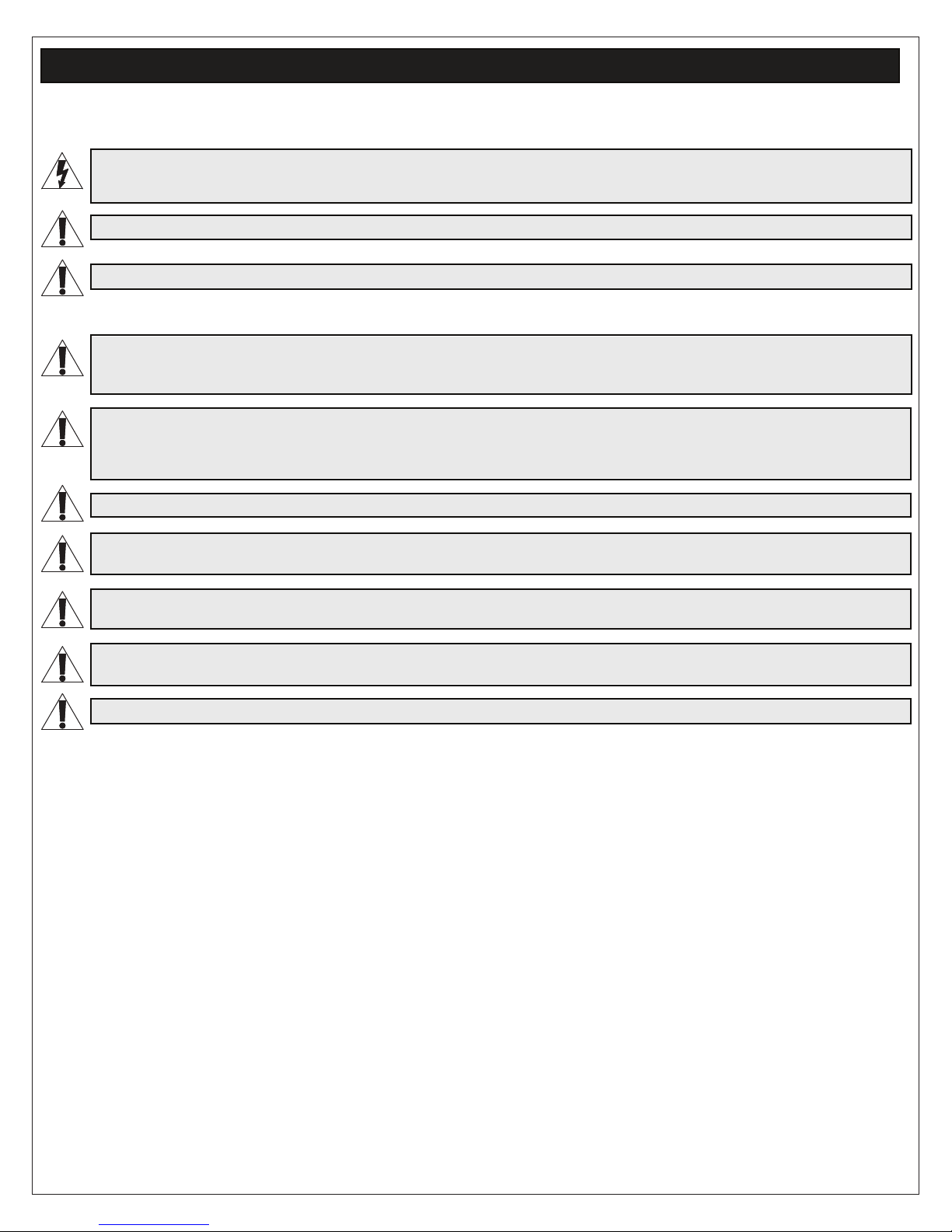
SUPPLIED COMPONENTS AND HARDWARE
Trough
A
Model Qty.
1-Piece Tabletop
2-Piece Tabletop
Lock
Washer
5/16” x 1 3/4”
Bolt With Lock
Flat
Washer
and Flat Washer
Model Qty.
1-Piece Tabletop
2-Piece Tabletop
Tabletop
D
Model Qty.
1
2
End Pedestal Base
(2x)
B
Center Pedestal Base
(2-Piece Tabletop Models Only)
C
1-Piece Tabletop
2-Piece Tabletop
1
2
#8 x 1 1/2”
Wood Screw
F
Model Qty.
1-Piece Tabletop
2-Piece Tabletop
E
*Standard hardware quantites for
12’ and 16’ 2-piece tabletops,
8
16
Amounts for custom tabletop
respectively.
lengths may vary.
14
28 or 36*
1-Piece Tabletop
2-Piece Tabletop
#8 x 1”
Wood Screw
G
Model Qty.
8
24
(6x)
Wood Biscuits
(2-Piece Tabletop Models Only)
H
(4x)
Joint Connector
(2-Piece Tabletop Models Only)
J
Page 4
(2x)
Mending Plate
(2-Piece Tabletop Models Only)
K
SUPPLIED COMPONENTS AND HARDWARE (CONTINUED)
SWING-OUT RACK (T5-TECH-KITXX)
(20x)
#10 x 5/8” Wood
Screw
L
(2x) 10-32 Oval
Nut
P
Model Qty.
1-Piece Tabletop
2-Piece Tabletop
2
4
1-Piece Tabletop
2-Piece Tabletop
(2x)
Lacing Strip
M
(2x) 10-32 x 1/2”
Flat Head Screw
R
Model Qty.
2
4
HDMI Retractors
N
Model Qty.
1-Piece Tabletop
2-Piece Tabletop
4
6
Power Mounting
Clip
S
Model Qty.
1-Piece Tabletop
2-Piece Tabletop
(2x)
Pivot Bracket
NOTE: Lengths vary based on table size.
Power Strip
T
Model Qty.
2
4
1-Piece Tabletop
2-Piece Tabletop
1
2
1-Piece Tabletop
2-Piece Tabletop
U
Model Qty.
1
2
Lever Lock
Adapter Brackets
X
V
Swing-Out Rack
W
Power Cable
(6x) 10-32 x 3/4”
Truss Screw With
Washer
Y
(2x)
2” Lever Lock
Plate
Z
Page 5
10” Lever Lock
Plate
AA
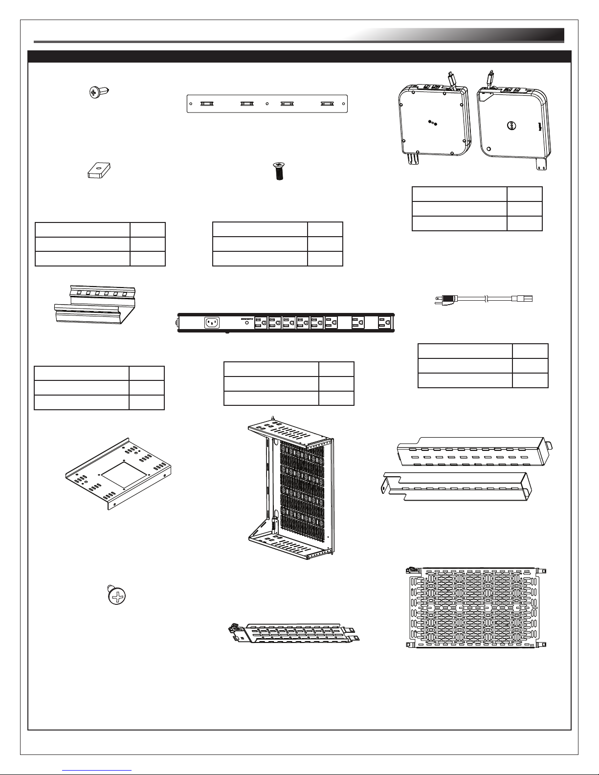
SUPPLIED COMPONENTS AND HARDWARE (CONTINUED)
SWING-OUT RACK (T5-TECH-KITXX)
(6x)
Lever Lock Securing Rivet
AB
(20x)
Lever Lock Plate Washer
AC
FAN OPTION (T5-DCFANKIT-1)
Face After Panel
AD
A/V Table Box
AE
Model Qty.
1-Piece Tabletop
2-Piece Tabletop
2
3
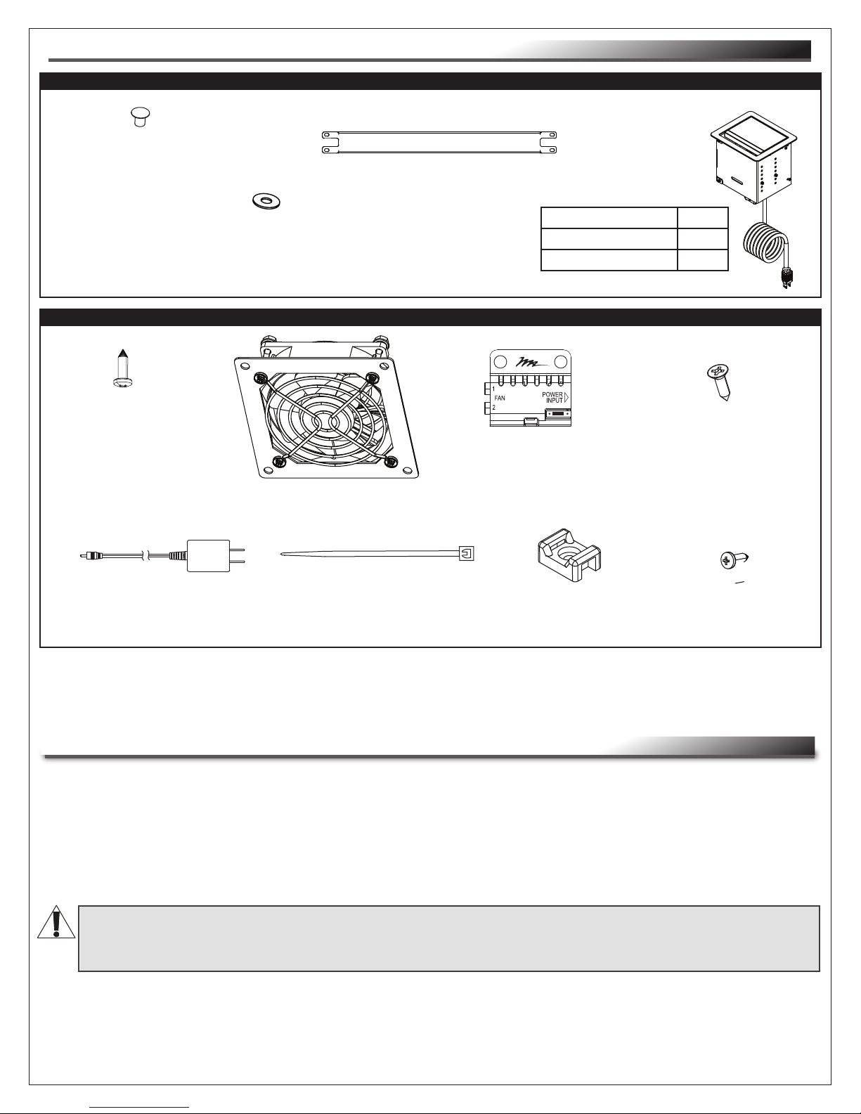
(8x)
10-32 x 3/8” Fan
Mounting Screw
AF
Fan Controller
Power Supply
AK
(2x)
Fan
AG
(12x)
Wire Tie
AL
Fan Controller
AH
(3x)
Tie Saddle
AM
NOTE: Additional hardware is included that may not be required for your installation.
REQUIRED TOOLS
• 4’ Level
• Saw Horses (or Stable Platform)
• Power Driver With 6” Long Phillips Bit or 6” Long #2 Phillips Screwdriver
• 5mm Hex Driver (Included)
• 7/16” Box Wrench
• 1/2” Socket Wrench
(2x)
#6 x 3/8” Fan
Controller Mounting
Screw
AJ
(3x) #10 x 5/8”
Tie Saddle Screw
AN
WARNING: Use tools with caution and follow all necessary safety protocols.
AVERTISSEMENT: Utiliser des outils avec prudence et suivre tous les protocoles de sécurité
nécessaires.
Page 6
INSTALLING TROUGHS TO PEDESTAL BASES
CAUTION: At least two people are required for pedestal, trough, and tabletop procedures.
ATTENTION: Au moins deux personnes sont requises pour les procédures de piédestal, de
quille et de table.
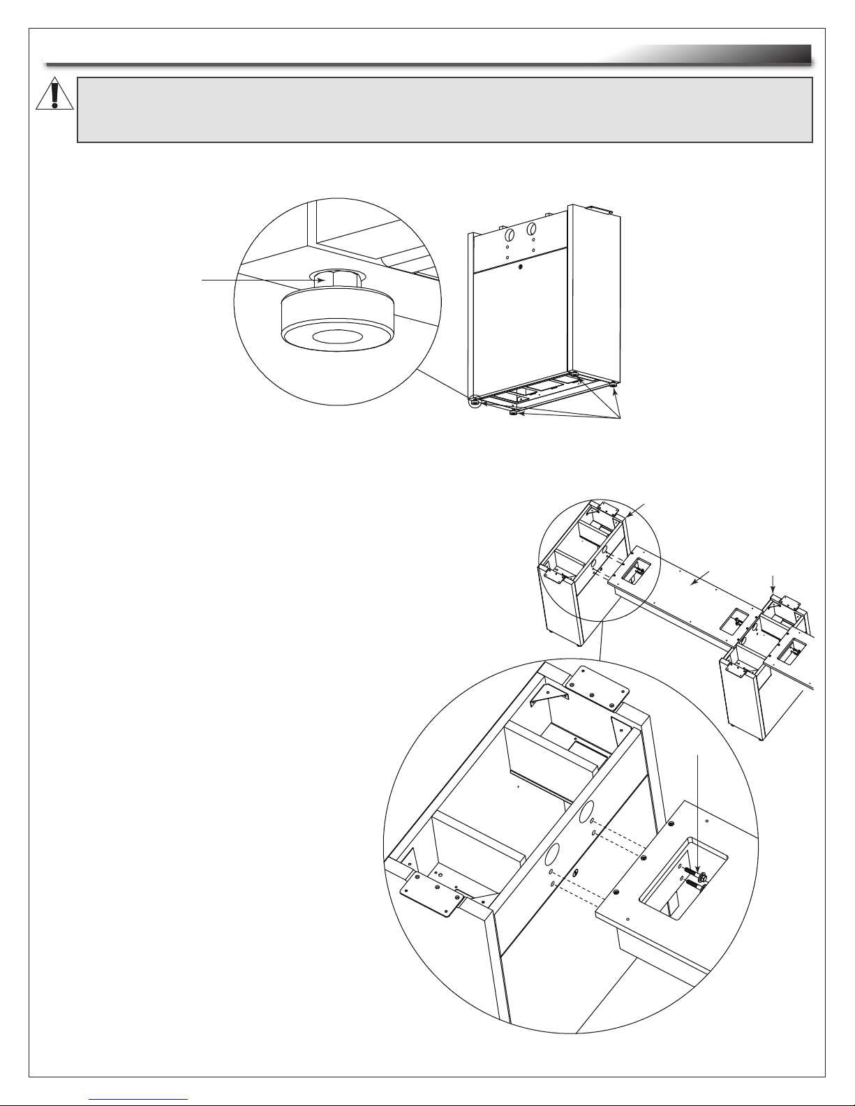
1. Before you begin, hand tighten all leveling glides on the pedestal bases as shown. (FIGURE A)
TIP: Use 7/16” box
wrench for nut
above leveling
glide, if necessary.
FIGURE A
2. Position end pedestal bases (B) with the doors facing each
other. If you have a 2-piece tabletop model, position the
center pedestal base (C) in between the ends. Space all
bases approximately one trough (A) length apart from each
other. (FIGURE B)
NOTE:
• A center pedestal base (C) is provided for
2-piece tabletop models. No center base
is provided for 1-piece models.
• Position center pedestal base (C) so the
door opens from the desired side.
3. Use a 1/2” socket and (16x for 2-piece
tabletop models, 8x for 1-piece models)
5/16” x 2” bolts with washers (E) to
attach the troughs (A) to the pedestal
bases (B and C).
Leveling Glide
Locations
B
E
A
C
NOTE: First, loosely attach all of the
5/16” x 2” bolts with washers (E), and then
tighten them. Do not overtighten.
Page 7
FIGURE B
INSTALLING TROUGHS TO PEDESTAL BASES (CONTINUED)
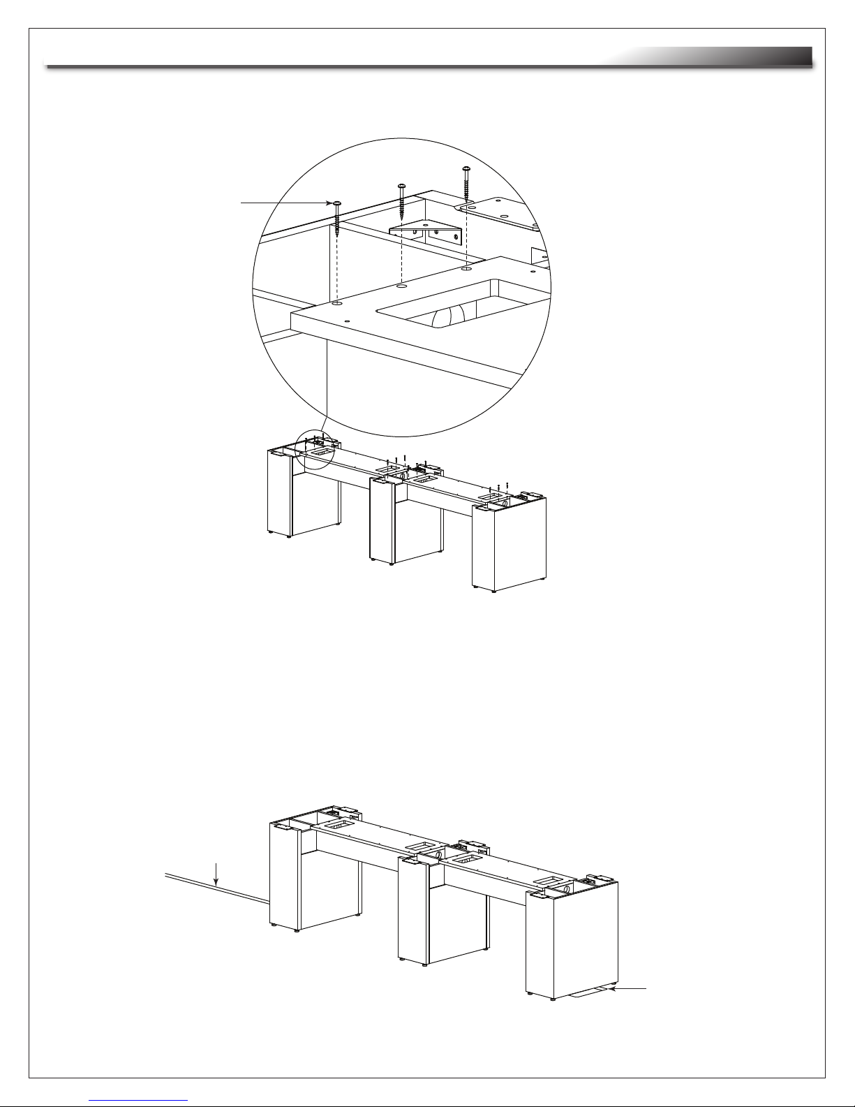
4. Use power driver or screwdriver and (12x for 2-piece tabletop models, 6x for 1-piece models) 1 1/2”
wood screws (F) to finish installing the troughs to the pedestal bases as shown. (FIGURE C)
NOTE: Use the 1
1/2" wood screws
(F) and not the 1"
wood screws (G)
for this step.
F
FIGURE C
5. With the troughs fully installed to the pedestal bases, place the entire assembly over any floor boxes
and where any over floor raceway ends as needed. (FIGURE D)
NOTE:
• Pull floor box cables before placing the assembly for access from inside the pedestal bases.
• Over floor raceway and floor box provided as examples.
Over Floor
Raceway
Floor
Box
FIGURE D
Page 8
 Loading...