

Middle Atlantic Products RM-KB-LCD17x8KVM, RM-KB-LCD17x16KVM User Manual

Dual Rail 8-Port & 16-Port LCD KVM Switch
RM-KB-LCD17x8KVM
RM-KB-LCD17x16KVM
User Manual
Phone: 973 839 1011
www.middleatlantic.com
I-00386-2 Rev B

RM-KB-LCD17x8/16KVM User Manual
FCC Information
This is an FCC Class A product. In a domestic environment this product may
cause radio interference in which case the user may be required to take
adequate measures.
This equipment has been tested and found to comply with the limits for a Class
A digital device, pursuant to Part 15 of the FCC Rules. These limits are
designed to provide reasonable protection against harmful interference when
the equipment is operated in a commercial environment. This equipment
generates, uses and can radiate radio frequency energy and, if not installed and
used in accordance with the instruction manual, may cause harmful
interference to radio communications. Operation of this equipment in a
residential area is likely to cause harmful interference in which case the user
will be required to correct the interference at his own expense.
RoHS
This product is RoHS compliant.
ii

RM-KB-LCD17x8/16KVM User Manual
User Notice
All information, documentation, and specifications contained in th is manual
are subject to change without prior notification by the manufacturer. The
manufacturer makes no representations or warranties, either expressed or
implied, with respect to the contents hereof and specifically disclaims any
warranties as to merchantability or fitness for any particular purpose. Any of
the manufacturer's software described in this manual is sold or licensed as is.
Should the programs prove defective following their purchase, the buyer (and
not the manufacturer, its distributor, or its dealer), assumes the entire cost of all
necessary servicing, repair and any incidental or consequential damages
resulting from any defect in the software.
The manufacturer of this system is not responsible for any radio and/or TV
interference caused by unauthorized modifications to this devi ce. It is the
responsibility of the user to correct such interference.
The manufacturer is not responsible for any damage incurred in the operation
of this system if the correct operational voltage setting was not selected prior
to operation. PLEASE VERIFY THAT THE VOLTAGE SETTING IS
CORRECT BEFORE USE.
iii

RM-KB-LCD17x8/16KVM User Manual
Package Contents
The RM-KB-LCD17x8/16KVM package consists of:
1 RM-KB-LCD17x8/16KVM Switch
1 Easy Installation Rack Mount Kit (includes four bracket screws)
8 Rack Mount Screws with Washers
4 10 feet (3 meters) Hybrid KVM Cable (for RM-KB-LCD17x8KVM)
8 10 feet (3 meters) Hybrid KVM Cable (for RM-KB-LCD17x16KVM)
1 Five in One USB/PS2 Console Cable
1 Firmware Upgrade Cable
1Power Cord
1 Grounding Wire
1 User Manual (Soft copy in CD)*
1 Quick Start Guide
Check to make sure that all the components are present and that nothing got
damaged in shipping. If you encounter a problem, contact your dealer.
Read this manual thoroughly and follow the instal lation and operation
procedures carefully to prevent any damage to the unit, and/or any of the
devices connected to it.
* Features may have been added to the RM-KB-LCD17x8/16KVM since this
manual was released. Please visit our website at www.middleatlantic.com to
download the most up-to-date version of the manual.
iv

RM-KB-LCD17x8/16KVM User Manual
Contents
FCC Information . . . . . . . . . . . . . . . . . . . . . . . . . . . . . . . . . . . . . . . . . . . . . ii
RoHS. . . . . . . . . . . . . . . . . . . . . . . . . . . . . . . . . . . . . . . . . . . . . . . . . . . . . . ii
User Notice . . . . . . . . . . . . . . . . . . . . . . . . . . . . . . . . . . . . . . . . . . . . . . . . .iii
Package Contents. . . . . . . . . . . . . . . . . . . . . . . . . . . . . . . . . . . . . . . . . . . iv
About this Manual . . . . . . . . . . . . . . . . . . . . . . . . . . . . . . . . . . . . . . . . . . .viii
Conventions . . . . . . . . . . . . . . . . . . . . . . . . . . . . . . . . . . . . . . . . . . . . . . . ix
1. Introduction
Overview. . . . . . . . . . . . . . . . . . . . . . . . . . . . . . . . . . . . . . . . . . . . . . . . . . .1
Features . . . . . . . . . . . . . . . . . . . . . . . . . . . . . . . . . . . . . . . . . . . . . . . . . . .3
Requirements . . . . . . . . . . . . . . . . . . . . . . . . . . . . . . . . . . . . . . . . . . . . . . .5
External Console. . . . . . . . . . . . . . . . . . . . . . . . . . . . . . . . . . . . . . . . . .5
Computers. . . . . . . . . . . . . . . . . . . . . . . . . . . . . . . . . . . . . . . . . . . . . . .5
Cables. . . . . . . . . . . . . . . . . . . . . . . . . . . . . . . . . . . . . . . . . . . . . . . . . .5
Operating Systems . . . . . . . . . . . . . . . . . . . . . . . . . . . . . . . . . . . . . . . .6
Components . . . . . . . . . . . . . . . . . . . . . . . . . . . . . . . . . . . . . . . . . . . . . . . .7
Front View. . . . . . . . . . . . . . . . . . . . . . . . . . . . . . . . . . . . . . . . . . . . . . .7
Rear View . . . . . . . . . . . . . . . . . . . . . . . . . . . . . . . . . . . . . . . . . . . . . . .9
2. Hardware Setup
Overview. . . . . . . . . . . . . . . . . . . . . . . . . . . . . . . . . . . . . . . . . . . . . . . . . .11
Before you Begin. . . . . . . . . . . . . . . . . . . . . . . . . . . . . . . . . . . . . . . . . . . .11
Rack Mounting . . . . . . . . . . . . . . . . . . . . . . . . . . . . . . . . . . . . . . . . . . . . .12
Grounding . . . . . . . . . . . . . . . . . . . . . . . . . . . . . . . . . . . . . . . . . . . . . . . . .15
Single Level Installation . . . . . . . . . . . . . . . . . . . . . . . . . . . . . . . . . . . . . .16
Cabling Diagrams . . . . . . . . . . . . . . . . . . . . . . . . . . . . . . . . . . . . . . . .18
3. Basic Operation
Opening the Console . . . . . . . . . . . . . . . . . . . . . . . . . . . . . . . . . . . . . . . .19
Opening Separately. . . . . . . . . . . . . . . . . . . . . . . . . . . . . . . . . . . . . . .19
Opening Together . . . . . . . . . . . . . . . . . . . . . . . . . . . . . . . . . . . . . . . .21
Closing the Console . . . . . . . . . . . . . . . . . . . . . . . . . . . . . . . . . . . . . . . . .22
Operating Precautions. . . . . . . . . . . . . . . . . . . . . . . . . . . . . . . . . . . . .24
Powering Off and Restarting. . . . . . . . . . . . . . . . . . . . . . . . . . . . . . . . . . .25
LCD On Screen Display (OSD) Configuration . . . . . . . . . . . . . . . . . . . . .26
The LCD Buttons. . . . . . . . . . . . . . . . . . . . . . . . . . . . . . . . . . . . . . . . .26
LCD Adjustment Settings . . . . . . . . . . . . . . . . . . . . . . . . . . . . . . . . . .27
Hot Plugging . . . . . . . . . . . . . . . . . . . . . . . . . . . . . . . . . . . . . . . . . . . . . . .28
Hot Plugging KVM Ports . . . . . . . . . . . . . . . . . . . . . . . . . . . . . . . . . . .28
Hot Plugging External Console Ports . . . . . . . . . . . . . . . . . . . . . . . . .28
Port Selection . . . . . . . . . . . . . . . . . . . . . . . . . . . . . . . . . . . . . . . . . . . . . .29
Manual Port Switching. . . . . . . . . . . . . . . . . . . . . . . . . . . . . . . . . . . . .29
Port ID Numbering . . . . . . . . . . . . . . . . . . . . . . . . . . . . . . . . . . . . . . . . . .29
USB Peripheral Devices . . . . . . . . . . . . . . . . . . . . . . . . . . . . . . . . . . . . . .29
v

RM-KB-LCD17x8/16KVM User Manual
4. On Screen Display (OSD) Operation
OSD Overview . . . . . . . . . . . . . . . . . . . . . . . . . . . . . . . . . . . . . . . . . . . . .31
OSD Login . . . . . . . . . . . . . . . . . . . . . . . . . . . . . . . . . . . . . . . . . . . . . . . .31
OSD Hotkey . . . . . . . . . . . . . . . . . . . . . . . . . . . . . . . . . . . . . . . . . . . . . . .31
OSD Main Screen. . . . . . . . . . . . . . . . . . . . . . . . . . . . . . . . . . . . . . . . . . . 32
OSD Main Screen Headings. . . . . . . . . . . . . . . . . . . . . . . . . . . . . . . . . . .33
OSD Navigation . . . . . . . . . . . . . . . . . . . . . . . . . . . . . . . . . . . . . . . . . . . .33
OSD Functions . . . . . . . . . . . . . . . . . . . . . . . . . . . . . . . . . . . . . . . . . . . . . 34
F1: GOTO. . . . . . . . . . . . . . . . . . . . . . . . . . . . . . . . . . . . . . . . . . . . . .34
F2: LIST . . . . . . . . . . . . . . . . . . . . . . . . . . . . . . . . . . . . . . . . . . . . . . .35
F3: SET. . . . . . . . . . . . . . . . . . . . . . . . . . . . . . . . . . . . . . . . . . . . . . . . 36
F4: ADM . . . . . . . . . . . . . . . . . . . . . . . . . . . . . . . . . . . . . . . . . . . . . . .38
F5: SKP. . . . . . . . . . . . . . . . . . . . . . . . . . . . . . . . . . . . . . . . . . . . . . . . 41
F6: BRC . . . . . . . . . . . . . . . . . . . . . . . . . . . . . . . . . . . . . . . . . . . . . . .42
F7: SCAN . . . . . . . . . . . . . . . . . . . . . . . . . . . . . . . . . . . . . . . . . . . . . .43
F8: LOUT . . . . . . . . . . . . . . . . . . . . . . . . . . . . . . . . . . . . . . . . . . . . . .43
5. Keyboard Port Operation
Hotkey Port Control . . . . . . . . . . . . . . . . . . . . . . . . . . . . . . . . . . . . . . . . .45
Invoke Hotkey Mode. . . . . . . . . . . . . . . . . . . . . . . . . . . . . . . . . . . . . . . . .45
Number Lock and Minus Keys . . . . . . . . . . . . . . . . . . . . . . . . . . .45
Control and F12 Keys . . . . . . . . . . . . . . . . . . . . . . . . . . . . . . . . . . 46
Select the Active Port . . . . . . . . . . . . . . . . . . . . . . . . . . . . . . . . . . . . . . . . 46
Auto Scan Mode. . . . . . . . . . . . . . . . . . . . . . . . . . . . . . . . . . . . . . . . . . . . 47
Invoking Auto Scan: . . . . . . . . . . . . . . . . . . . . . . . . . . . . . . . . . . . . . . 47
Skip Mode. . . . . . . . . . . . . . . . . . . . . . . . . . . . . . . . . . . . . . . . . . . . . . . . .47
Computer Keyboard / Mouse Reset . . . . . . . . . . . . . . . . . . . . . . . . . . . . . 48
Hotkey Beeper Control . . . . . . . . . . . . . . . . . . . . . . . . . . . . . . . . . . . . . . .49
Quick Hotkey Control . . . . . . . . . . . . . . . . . . . . . . . . . . . . . . . . . . . . . . . .49
OSD Hotkey Control. . . . . . . . . . . . . . . . . . . . . . . . . . . . . . . . . . . . . . . . .49
Port OS Control . . . . . . . . . . . . . . . . . . . . . . . . . . . . . . . . . . . . . . . . . . . .50
Restore Default Values. . . . . . . . . . . . . . . . . . . . . . . . . . . . . . . . . . . . . . .50
Hotkey Summary Table . . . . . . . . . . . . . . . . . . . . . . . . . . . . . . . . . . . . . .51
6. The Firmware Upgrade Utility
Introduction. . . . . . . . . . . . . . . . . . . . . . . . . . . . . . . . . . . . . . . . . . . . . . . .53
Downloading the Firmware Upgrade Package . . . . . . . . . . . . . . . . . . 53
Preparation. . . . . . . . . . . . . . . . . . . . . . . . . . . . . . . . . . . . . . . . . . . . . . . .54
Starting the Upgrade. . . . . . . . . . . . . . . . . . . . . . . . . . . . . . . . . . . . . . . . .55
Upgrade Succeeded. . . . . . . . . . . . . . . . . . . . . . . . . . . . . . . . . . . . . . . . .56
Upgrade Failed. . . . . . . . . . . . . . . . . . . . . . . . . . . . . . . . . . . . . . . . . . . . .56
Firmware Upgrade Recovery . . . . . . . . . . . . . . . . . . . . . . . . . . . . . . . . . .57
Appendix
Safety Instructions . . . . . . . . . . . . . . . . . . . . . . . . . . . . . . . . . . . . . . . . . . 59
General . . . . . . . . . . . . . . . . . . . . . . . . . . . . . . . . . . . . . . . . . . . . . . . .59
Rack Mounting . . . . . . . . . . . . . . . . . . . . . . . . . . . . . . . . . . . . . . . . . . 61
vi

RM-KB-LCD17x8/16KVM User Manual
Technical Support. . . . . . . . . . . . . . . . . . . . . . . . . . . . . . . . . . . . . . . . . . .61
Specifications . . . . . . . . . . . . . . . . . . . . . . . . . . . . . . . . . . . . . . . . . . . . . .62
Clear Login Information . . . . . . . . . . . . . . . . . . . . . . . . . . . . . . . . . . . . . . .63
OSD Factory Default Settings. . . . . . . . . . . . . . . . . . . . . . . . . . . . . . . . . .64
Troubleshooting . . . . . . . . . . . . . . . . . . . . . . . . . . . . . . . . . . . . . . . . . . . .64
Overview . . . . . . . . . . . . . . . . . . . . . . . . . . . . . . . . . . . . . . . . . . . . . . .64
Dedicated Invocation Keys . . . . . . . . . . . . . . . . . . . . . . . . . . . . . . . . . . . .65
About SPHD Connectors . . . . . . . . . . . . . . . . . . . . . . . . . . . . . . . . . . . . .65
vii

RM-KB-LCD17x8/16KVM User Manual
About this Manual
This user manual is provided to help you get the most from your RM-KBLCD17x8/16KVM system. It covers all aspects of installation, configuration
and operation. An overview of the information found in the manual is provided
below.
Chapter 1, Introduction, introduces you to the RM-KB-LCD17x8/16KVM
system. Its purpose, features and benefits are presented, and its front and back
panel components are described.
Chapter 2, Hardware Setup, describes how to set up your installation.
Chapter 3, Basic Operation, explains the fundamental concepts involved
in operating the RM-KB-LCD17x8/16KVM.
Chapter 4, On Screen Display (OSD) Operation, provides a complete
description of the RM-KB-LCD17x8/16KVM's on-screen display (OSD), and
how to work with it.
Chapter 5, Keyboard Port Operation, details all of the concepts and
procedures involved in the hotkey operation of your RM-KB-LCD17x8/
16KVM installation.
Chapter 6, The Firmware Upgrade Utility, explains how to use this
utility to upgrade the RM-KB-LCD17x8/16KVM's firmware with the latest
available versions.
An Appendix, provides specifications and other technical information
regarding the RM-KB-LCD17x8/16KVM.
viii

Conventions
This manual uses the following conventions:
Monospaced Indicates text that you should key in.
[ ] Indicates keys you should press. For example, [Enter] means to
press the Enter key. If keys need to be chorded, they appear
together in the same bracket with a plus sign between them:
[Ctrl+Alt].
1. Numbered lists represent procedures with sequential steps.
♦ Bullet lists provide information, but do not involve sequential steps.
→ Indicates selecting the option (on a menu or dialog box, for
example), that comes next. For example, Start
open the Start menu, and then select Run.
Indicates critical information.
RM-KB-LCD17x8/16KVM User Manual
→ Run means to
ix

RM-KB-LCD17x8/16KVM User Manual
This Page Intentionally Left Blank
x

Chapter 1
Introduction
Overview
The RM-KB-LCD17x8/16KVM switch is an integrated LCD console and
keyboard, video, and mouse (KVM) switch that offers secure access to 8 or 16
attached computers and mounts in only 1U of rack space. It features an
independently retractable 17” LCD monitor and keyboard with built-in
touchpad. To maximize space in your data center, the keyboard/touchpad
module hides away when not in use, while the thin profile LCD monitor rotates
back – flush against the rack – allowing convenient monitoring of computer
activity.
An extra console port is provided on the rear panel to manage the LCD KVM
switch from an external console (monitor, keyboard, and mouse) up to 20
meters away. For added convenience it also supports an external USB mouse.
The RM-KB-LCD17x8/16KVM supports both PS/2 and USB keyboards and
mice for the connected computers, and supports USB peripheral devices to be
used with the attached computers. A single RM-KB-LCD17x8/16KVM can
control up to 8 or 16 computers.
Your RM-KB-LCD17x8/16KVM investment is protecte d by an incl uded
firmware upgrade utility. You can stay current with the latest functionality
improvements by downloading firmware update files from our website as they
become available, and using the utility to quickly and conveniently perform the
upgrade.
Setup is fast and easy: plugging cables into their appropriate ports is all that is
entailed. Because the RM-KB-LCD17x8/16KVM intercepts keyboard input
directly, there is no software to configure, no need to get involved in complex
installation routines, nor any need to be concerned with incompatibility
problems.
Access to any computer connected to the installation is easily accomplished
either by entering hotkey combinations from the keyboard, or by means of a
powerful, mouse driven, OSD (on-screen display) menu system. A convenient
Auto Scan feature also permits automatic scanning and monitoring of the
activities of all computers running on the installation one by one.
1

RM-KB-LCD17x8/16KVM User Manual
There is no better way to save time and money than with a RM-KB-LCD17x8/
16KVM installation. By using the RM-KB-LCD17x8/16KVM with its sliding
LCD console to manage your installation, you eliminate the expense of having
to purchase a separate keyboard, monitor, and mouse for each computer; save
all the space those extra components would take up; save the space that a
keyboard, monitor, and mouse would take with a standard KVM switch; save
on energy costs; and eliminate the inconvenience and wasted effort involved in
constantly moving from one computer to another.
2

1. Introduction
Features
Integrated KVM console with a 17” LCD monitor in a dual rail housing
Dual rail design allows LCD monitor and keyboard/touchpad to operate
independently
Easy Installation Rack Mount Kit (for one-person installation)
Space saving technology – up to two consoles (one bus) control up to 8 or
16 computers
Dual Interface – supports computers with PS/2 or USB keyboards and mice
USB port allows each computer to access USB peripherals
1
Multiplatform support – Windows 2000/XP/Vista, Linux, Mac, and Sun
Supports multimedia USB keyboards for PC, Mac and Sun
Auto PS/2 and USB interface detection
Keyboard and mouse emulation (PS/2 and USB) for smooth switching and
simultaneous booting of multiple computers even when the console focus
is elsewhere
Superior video quality – supports resolutions up to 1280 x 1024 @ 75 Hz
No software required – convenient computer selection via mouse-driven,
intuitive OSD (on-screen display) menus and hotkeys
Two level password securit y – authorized users view and cont rol computers
Supports one administrator and four user accounts with separate profiles
Auto Scan mode enables continuous monitoring of user-selected computers
Broadcast support – commands from the keyboard can be broadcast to all
available computers on the installation
Hot pluggable – add or remove computers without having to power down
the switch
Beeper on/off via hotkey and OSD
Extra console port – manage computers from an external console (monitor,
USB or PS/2 keyboard and mouse)
Supports external USB mouse
Dedicated Hotkey mode and OSD Invocation Keys reduce the number of
keystrokes and provide quick access to these functions
1. The USB peripheral function only works with USB cable set connections. It will not
work with PS/2 cable set connections.
3

RM-KB-LCD17x8/16KVM User Manual
Locking mechanism to securely lock the keyboard drawer in the open
position
Security – Administrator/User password authorization for enhanced
security protection; Administrator access rights synchronized between
master and slave stations
OSD screen automatically adjusts to resolution changes
Two types of logout: manual and timed
Sliding housing is slightly less than 1U with top and bo ttom clearance for
smooth operation in 1U of rack space
DDC emulation – video settings of each computer are automatically
adjusted for optimal output to the monitor
Standard 105-key keyboard
Keyboard status restored when switching computers
4

1. Introduction
Requirements
External Console
The following hardware components are required for the external console:
A VGA, SVGA, or multisync monitor capable of displaying the highest
resolution provided by any computer in the installation.
A USB or PS/2 keyboard and mouse
Computers
The following equipment must be installed on each computer:
A VGA, SVGA, or multisync video graphics card with an HDB-15 port.
Note: The integrated LCD monitor's maximum resolution is
1280 x 1024 @ 75 Hz. Make sure that none of the computer
resolution settings exceed the LCD monitor's maximum resolution.
PS/2 mouse and keyboard ports (6-pin Mini-DIN), or at least one USB port.
Cables
Substandard cables may damage the connected devices or degrade overall
performance. For optimum signal integrity and to simplify the layout, w e
strongly recommend that you use the high quality Hybrid Cable sets as
provided in the package.
Note: You can also purchase an additional 4-pack of Hybrid cables on ou r
website (www.middleatlantic.com). Part no.: PS2/USB-4C
5
RM-KB-LCD17x8/16KVM User Manual
Operating Systems
Supported operating systems are shown in the table, below:
OS Version
Windows 2000 and higher
Linux RedHat 7.1 and higher
SuSE 9.0 and higher
Mandriva (Mandrake) 9.0 and higher
UNIX AIX 4.3 and higher
FreeBSD 4.2 and higher
Sun Solaris 8 and higher
Novell Netware 5.0 and higher
Mac OS 9 and higher
DOS 6.22
6
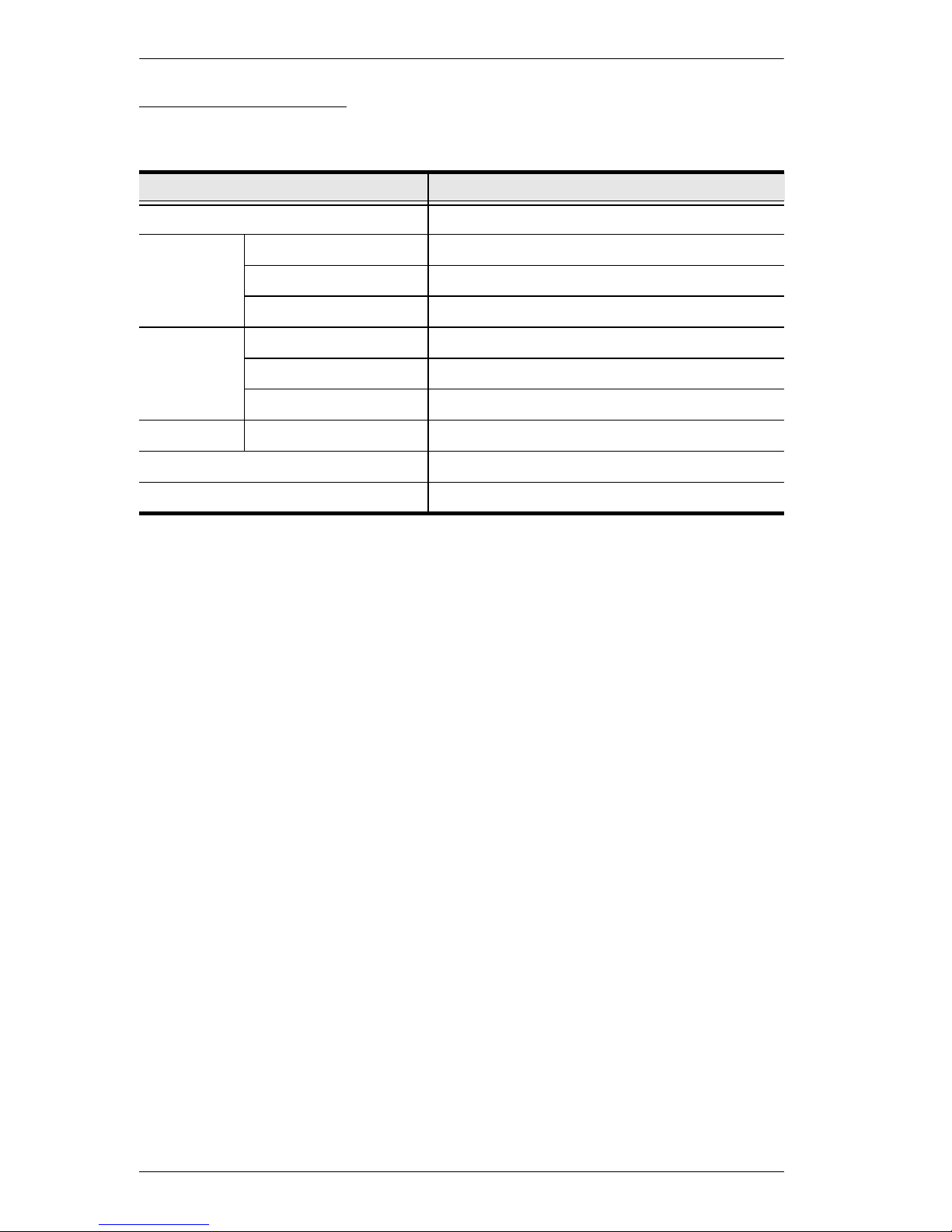
Components
Front View
5
1. Introduction
1
2
3
4
14
6
7
8
9
10
11
13
12
7

RM-KB-LCD17x8/16KVM User Manual
No. Component Description
1 Handle Pull to slide the KVM module out; push to slide the module in
(see item 2 in this table).
2 LCD Display After sliding the KVM module out, flip up the cover to access
the LCD monitor.
3 LCD Controls The LCD On/Off switch is located here, as well as buttons to
control the position and picture settings of the LCD display.
See page 26 for details.
4 Port LEDs An ON LINE LED lights to indicate that the computer
attached to its corresponding port is up and running.
5 Keyboard Standard 105-key keyboard
6 Touchpad Standard mouse touchpad
7 Port Switches Press the UP or DOWN buttons for the Port ID to bring the
KVM focus to the computer attached to the corresponding
port. See Manual Port Switching, page 29.
8 External Mouse
Port
9 Power LED Lights to indicate that the unit is receiving power.
10 Rack Mounting
Brackets
11 Lock LEDs Num Lock, Caps Lock, Scroll Lock LEDs are located here.
12 Reset Switch Located to the right of the Lock LEDs. Press this recessed
13 USB Port The USB port is available to connect a USB 1.1 peripheral
14 Firmware
Upgrade
Section
A USB mouse port is provided for users who prefer to use an
external mouse.
The rack mount brackets located at each corner of the unit
secure the chassis to a system rack.
switch in with a small object to perform a system reset.
device (flash drive, CD-ROM drive, etc.) to the switch.
Firmware Upgrade Port: The Firmware Upgrade Cable
that transfers the firmware upgrade data from the administrator's computer to the RM-KB-LCD17x8/16KVM plugs
into this RJ-11 connector.
Firmware Upgrade Switch: During no rmal operation this
switch should be in the NORMAL position. (See The Firm-
ware Upgrade Utility, page 53 for firmware upgrading
details.)
8
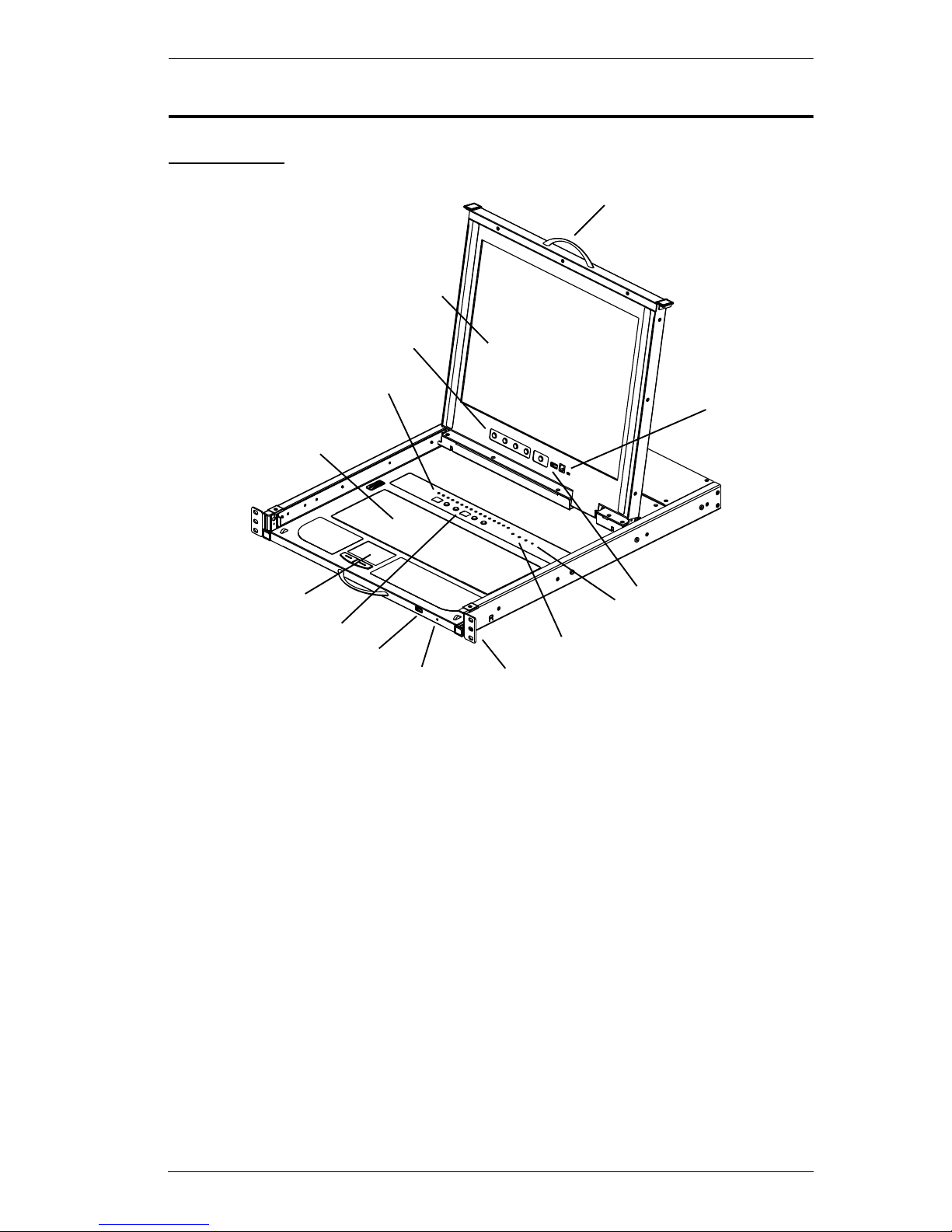
1. Introduction
123 45
Rear View
No. Component Description
1 Power Socket This is a standard 3-prong AC power socket. The power cord
from an AC source plugs in here.
2 Power Switch This standard rocker switch powers the unit on and off.
3 Grounding
Terminal
4 External
Console Port
5 KVM Port
Section
The grounding wire used to ground the switch attaches here.
For flexibility and convenience, the RM-KB-LCD17x8/16KVM
supports an independent, external, KVM console.
The external console keyboard, monitor, and mouse cables
plug in here.
The cables that link to the computers plug in here.
Note: The shape of these SPHD connectors has been
specifically modified so that only KVM cables designed to
work with this switch can plug in (see the Cables section on
page 5, for details). Do NOT attempt to use ordinary 15 pin
VGA connector cables to link these ports to the computers.
9

RM-KB-LCD17x8/16KVM User Manual
This Page Intentionally Left Blank
10

Chapter 2
1. Important safety information regarding the placement of this
device is provided on page 59. Please review it before proceeding.
2. Make sure that the power to all devices connected to the
installation are turned off. Y ou must unplug the power cords of any
computers that have the Keyboard Power On function.
Hardware Setup
Overview
For convenience and flexibility that allows mixing PS/2 and USB interfaces,
the RM-KB-LCD17x8/16KVM design utilizes custom KVM cables that serve
as intermediaries between the KVM switch and the connected computers.
A separate custom KVM cable is required for each computer connection.
Consult your dealer to find out which custom KVM cables best fit your needs.
Before you Begin
Note: Allow at least 2 inches (5.1 cm) on each side for proper ventilation, and
at least 5 inches (12.7 cm) at the back for the power cord and cable
clearance.
11
RM-KB-LCD17x8/16KVM User Manual
Support
Flange
Rear Flange
Slide Bar
Rear Attachment
Sliding Bracket
Rear Flange
LEFT
RAIL
RIGHT
RAIL
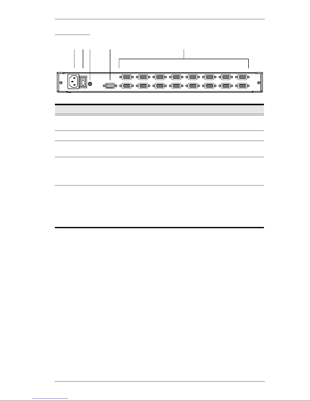
Rack Mounting
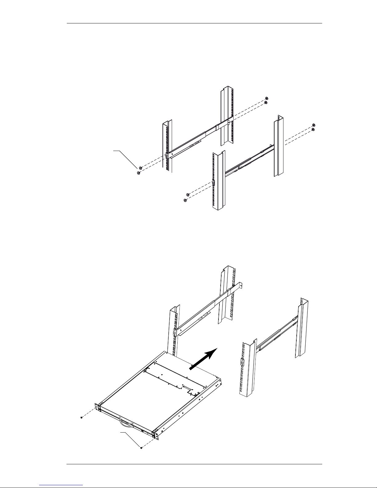
To rack mount the RM-KB-LCD17x8/16KVM, do the following:
1. Attach the left and right mounting rails to the inside of the rack with the
rack mount screws provided. The flange that supports the switch will be to
the inside.
12
2. Hardware Setup
HP 10-32 thread,
¾ inch
Phillips I head
M4L6
a) Screw the front flanges to the rack first.
b) Slide the bars with the rear flanges toward the rack until the flanges
make contact with the rack, then screw the rear flanges to the rack.
2. Slide the switch onto the support flanges. Use the bracket screws supplied
with this package to loosely attach the front of the switch to the front of the
rack (only tighten the screws part way).
13
RM-KB-LCD17x8/16KVM User Manual
3. Slide the rear attachment sliding brackets along the slide bars until they
contact the rear of the switch, then use the bracket screws supplied with
this package to attach the bars to the rear of the switch (tighten the screws
all the way).
Phillips I head
M4L6
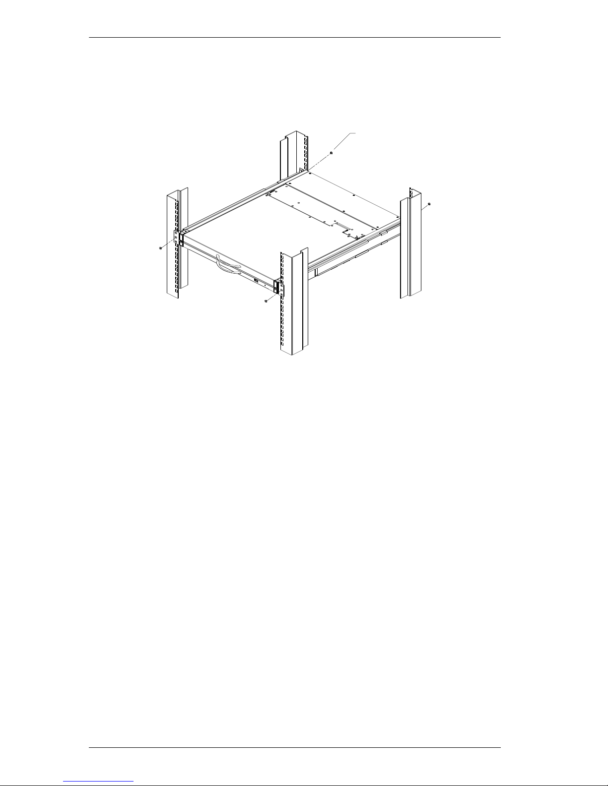
4. Slide the switch open and closed a couple of times to be sure that it is
properly aligned and operating smoothly. (See p. 19 for opening and
closing procedures.)
5. After determining that the switch is properly lined up and operating
correctly, finish up by fully tightening down the partially tightened front
attached bracket screws inserted in step 2.
14
 Loading...