

Middle Atlantic Products RM-KB-LCD17KVMHD User Manual
User Manual
RM-KB-LCD17KVMHD
Dual Rail 8-Port LCD
KVM Switch
I-00722 Rev B

RM-KB-LCD17KVMHD User Manual
FCC, CE Information
FEDERAL COMMUNICATIONS COMMISSION INTERFERENCE
STATEMENT: This equipment has been tested and found to comply with the
limits for a Class A digital device, pursuant to Part 15 of the FCC Rules. These
limits are designed to provide reasonable protection against harmful
interference when the equipment is operated in a commercial environment.
This equipment generates, uses, and can radiate radio frequency energy and, if
not installed and used in accordance with the instruction manual, may cause
harmful interference to radio communications. Operation of this equipment in
a re
sidential area is likely to cause harmful interference in which case the user
will be required to correct the interference at his own expense.
FCC Caution: Any changes or modifications not expressly approved by the
party responsible for compliance could void the user's authority to operate this
equipment.
CE Warning: This is a class A product. In a domestic environment this product
may cause radio interference in which case the user may be required to take
adequate measures.
RoHS
This product is RoHS compliant.
Telephone Support
Corporate Headquarters
Corporate Voice 973-839-1011 - Fax 973-839-1976 / International Voice +1
973-839-8821 - Fax +1 973-839-4982
middleatlantic.com - info@middleatlantic.com
Middle Atlantic Canada
Voice 613-836-2501 - Fax 613-836-2690 / middleatlantic.ca customerservicecanada@middleatlantic.ca
i

RM-KB-LCD17KVMHD User Manual
User Notice
All information, documentation, and specifications contained in this manual
are subject to change without prior notification by the manufacturer. The
manufacturer makes no representations or warranties, either expressed or
implied, with respect to the contents hereof and specifically disclaims any
warranties as to merchantability or fitness for any particular purpose. Any of
the manufacturer's software described in this manual is sold or licensed as is.
Should the programs prove defective following their purchase, the buyer (and
not the manufacturer, its distributor, or its dealer), assumes the entire cost of all
necessary servicing, repair and any incidental or consequential damages
resulting from any defect in the software.
The manufacturer of this system is not responsible for any radio and/or TV
interference caused by unauthorized modifications to this device. It is the
responsibility of the user to correct such interference.
The manufacturer is not responsible for any damage incurred in the operation
of this system if the correct operational voltage setting was not selected prior
to operation. PLEASE VERIFY THAT THE VOLTAGE SETTING IS
CORRECT BEFORE USE.
A typical LCD (Liquid Crystal Display) monitor has millions of pixels. A dead
pixel refers to a pixel with a defect in its ability to display the correct color
output. It most often looks like a tiny black or white spot on your screen,
although it can be any other color. Since even a tiny dust particle on one of the
pixels during the manufacturing process or a slight bump during shipping can
create a dead pixel, the ISO 13406-2 norm defines 4 classes of acceptable
screens with dead pixels--Class 1 is the best; Class 4 is the worst. Almost all
manufacturers use Class 2 to establish their warranties, which allows a certain
amount of dead pixels to exist before they will replace the screen. Since the
manufacturers consider these screens to be acceptable under ISO
specifications, we cannot be responsible for replacement or warranty of the
TFT LCD panel.
ii

RM-KB-LCD17KVMHD User Manual
Package Contents
Basic Package
The basic RM-KB-LCD17KVMHD package consists of:
1 RM-KB-LCD17KVMHD Rackmount LCD KVM switch
2 Custom USB DVI KVM Cable Set
1Power Cord
1 User Instructions*
1 Quick Start Guide
Check to make sure that all of the components are present and in good order.
If anything is missing, or was damaged in shipping, contact your dealer.
Read this manual thoroughly and follow the installation and operation
procedures carefully to prevent any damage to the console or to any other
devices on the RM-KB-LCD17KVMHD installation.
* Changes may have been made to the manual since it was published. Please
visit our web site to download the most up-to-date version of the manual
iii

RM-KB-LCD17KVMHD User Manual
Contents
FCC, CE Information. . . . . . . . . . . . . . . . . . . . . . . . . . . . . . . . . . . . . . . . . . i
RoHS. . . . . . . . . . . . . . . . . . . . . . . . . . . . . . . . . . . . . . . . . . . . . . . . . . . . . . i
Telephone Support . . . . . . . . . . . . . . . . . . . . . . . . . . . . . . . . . . . . . . . . . . . i
User Notice . . . . . . . . . . . . . . . . . . . . . . . . . . . . . . . . . . . . . . . . . . . . . . . . . ii
Package Contents. . . . . . . . . . . . . . . . . . . . . . . . . . . . . . . . . . . . . . . . . . . .iii
Basic Package. . . . . . . . . . . . . . . . . . . . . . . . . . . . . . . . . . . . . . . . . . . .iii
Conventions . . . . . . . . . . . . . . . . . . . . . . . . . . . . . . . . . . . . . . . . . . . . . . . . x
Chapter 1.
Introduction
Overview . . . . . . . . . . . . . . . . . . . . . . . . . . . . . . . . . . . . . . . . . . . . . . . . . . .1
Features . . . . . . . . . . . . . . . . . . . . . . . . . . . . . . . . . . . . . . . . . . . . . . . . . . .3
Requirements . . . . . . . . . . . . . . . . . . . . . . . . . . . . . . . . . . . . . . . . . . . . . . . 4
LCD Console . . . . . . . . . . . . . . . . . . . . . . . . . . . . . . . . . . . . . . . . . . . . .4
External Console . . . . . . . . . . . . . . . . . . . . . . . . . . . . . . . . . . . . . . . . . .4
Computers. . . . . . . . . . . . . . . . . . . . . . . . . . . . . . . . . . . . . . . . . . . . . . .4
Operating Systems . . . . . . . . . . . . . . . . . . . . . . . . . . . . . . . . . . . . . . . . 5
Components . . . . . . . . . . . . . . . . . . . . . . . . . . . . . . . . . . . . . . . . . . . . . . . . 6
Front View . . . . . . . . . . . . . . . . . . . . . . . . . . . . . . . . . . . . . . . . . . . . . . .6
Rear View . . . . . . . . . . . . . . . . . . . . . . . . . . . . . . . . . . . . . . . . . . . . . . .8
Chapter 2.
Hardware Setup
Before you Begin. . . . . . . . . . . . . . . . . . . . . . . . . . . . . . . . . . . . . . . . . . . . .9
Rack Mounting . . . . . . . . . . . . . . . . . . . . . . . . . . . . . . . . . . . . . . . . . . . . . .9
Connecting Up . . . . . . . . . . . . . . . . . . . . . . . . . . . . . . . . . . . . . . . . . . . . .12
Chapter 3.
Operation
Operating Precautions . . . . . . . . . . . . . . . . . . . . . . . . . . . . . . . . . . . . . . . 15
LCD OSD Configuration . . . . . . . . . . . . . . . . . . . . . . . . . . . . . . . . . . . . . .16
The LCD Buttons. . . . . . . . . . . . . . . . . . . . . . . . . . . . . . . . . . . . . . . . . 16
The Adjustment Settings . . . . . . . . . . . . . . . . . . . . . . . . . . . . . . . . . . .16
Hot Plugging . . . . . . . . . . . . . . . . . . . . . . . . . . . . . . . . . . . . . . . . . . . . . . .18
Powering Off and Restarting. . . . . . . . . . . . . . . . . . . . . . . . . . . . . . . . . . .18
USB Peripheral Devices . . . . . . . . . . . . . . . . . . . . . . . . . . . . . . . . . . . . . . 18
Chapter 4.
On Screen Display (OSD) Operation
OSD Overview . . . . . . . . . . . . . . . . . . . . . . . . . . . . . . . . . . . . . . . . . . . . .19
OSD Login. . . . . . . . . . . . . . . . . . . . . . . . . . . . . . . . . . . . . . . . . . . . . . . . . 19
OSD Hotkey . . . . . . . . . . . . . . . . . . . . . . . . . . . . . . . . . . . . . . . . . . . .20
OSD Main Screen . . . . . . . . . . . . . . . . . . . . . . . . . . . . . . . . . . . . . . . .21
OSD Navigation . . . . . . . . . . . . . . . . . . . . . . . . . . . . . . . . . . . . . . . . . . . .22
iv

RM-KB-LCD17KVMHD User Manual
OSD Functions . . . . . . . . . . . . . . . . . . . . . . . . . . . . . . . . . . . . . . . . . . . . . 23
F1: Help. . . . . . . . . . . . . . . . . . . . . . . . . . . . . . . . . . . . . . . . . . . . . . . . 23
F2: Rename Port Name . . . . . . . . . . . . . . . . . . . . . . . . . . . . . . . . . . . 23
F3: SET. . . . . . . . . . . . . . . . . . . . . . . . . . . . . . . . . . . . . . . . . . . . . . . . 24
F4: ADM . . . . . . . . . . . . . . . . . . . . . . . . . . . . . . . . . . . . . . . . . . . . . . . 26
F5: SCAN . . . . . . . . . . . . . . . . . . . . . . . . . . . . . . . . . . . . . . . . . . . . . . 29
F7: Close OSD . . . . . . . . . . . . . . . . . . . . . . . . . . . . . . . . . . . . . . . . . . 29
F8: Logout . . . . . . . . . . . . . . . . . . . . . . . . . . . . . . . . . . . . . . . . . . . . . . 29
Ctrl + T: Select Tree List . . . . . . . . . . . . . . . . . . . . . . . . . . . . . . . . . . . 30
Ctrl + L: Select favorites . . . . . . . . . . . . . . . . . . . . . . . . . . . . . . . . . . . 30
Ctrl + P: Toggle powered on . . . . . . . . . . . . . . . . . . . . . . . . . . . . . . . . 30
Ctrl + F: Search Port Name. . . . . . . . . . . . . . . . . . . . . . . . . . . . . . . . . 30
Ctrl + E: Edit favorites . . . . . . . . . . . . . . . . . . . . . . . . . . . . . . . . . . . . . 30
Ctrl + C: Port properties . . . . . . . . . . . . . . . . . . . . . . . . . . . . . . . . . . . 31
Chapter 5.
Keyboard Port Operation
Keyboard Operation . . . . . . . . . . . . . . . . . . . . . . . . . . . . . . . . . . . . . . . . . 33
Hotkey Summary Table . . . . . . . . . . . . . . . . . . . . . . . . . . . . . . . . . . . . . . 34
Chapter 6.
Remote Logging In
Overview. . . . . . . . . . . . . . . . . . . . . . . . . . . . . . . . . . . . . . . . . . . . . . . . . . 35
Local Console Login . . . . . . . . . . . . . . . . . . . . . . . . . . . . . . . . . . . . . . . . . 35
Browser Login. . . . . . . . . . . . . . . . . . . . . . . . . . . . . . . . . . . . . . . . . . . . . . 36
Windows Client AP Login . . . . . . . . . . . . . . . . . . . . . . . . . . . . . . . . . . . . . 37
The Windows Client AP Connection Screen. . . . . . . . . . . . . . . . . . . . 38
Connecting – Windows Client AP . . . . . . . . . . . . . . . . . . . . . . . . . . . . 39
The File Menu . . . . . . . . . . . . . . . . . . . . . . . . . . . . . . . . . . . . . . . . . . . 40
Java Client AP Login . . . . . . . . . . . . . . . . . . . . . . . . . . . . . . . . . . . . . . . . 41
The Java Client AP Connection Screen . . . . . . . . . . . . . . . . . . . . . . . 42
Connecting – Java Client AP . . . . . . . . . . . . . . . . . . . . . . . . . . . . . . . 43
Chapter 7.
Remote User Interface
The Web Browser Main Page. . . . . . . . . . . . . . . . . . . . . . . . . . . . . . . . . . 45
Page Components . . . . . . . . . . . . . . . . . . . . . . . . . . . . . . . . . . . . . . . 46
The Tab Bar . . . . . . . . . . . . . . . . . . . . . . . . . . . . . . . . . . . . . . . . . . . . 47
The AP GUI Main Page . . . . . . . . . . . . . . . . . . . . . . . . . . . . . . . . . . . . . . 48
The Control Panel. . . . . . . . . . . . . . . . . . . . . . . . . . . . . . . . . . . . . . . . . . . 49
WinClient Control Panel . . . . . . . . . . . . . . . . . . . . . . . . . . . . . . . . . . . 49
WinClient Control Panel Functions . . . . . . . . . . . . . . . . . . . . . . . . . . . 51
Video Settings. . . . . . . . . . . . . . . . . . . . . . . . . . . . . . . . . . . . . . . . . . . 53
Gamma Adjustment. . . . . . . . . . . . . . . . . . . . . . . . . . . . . . . . . . . . 56
The Message Board . . . . . . . . . . . . . . . . . . . . . . . . . . . . . . . . . . . . . . 57
Button Bar . . . . . . . . . . . . . . . . . . . . . . . . . . . . . . . . . . . . . . . . . . . 57
v

RM-KB-LCD17KVMHD User Manual
Message Display Panel . . . . . . . . . . . . . . . . . . . . . . . . . . . . . . . . .58
Compose Panel . . . . . . . . . . . . . . . . . . . . . . . . . . . . . . . . . . . . . . . 58
User List Panel . . . . . . . . . . . . . . . . . . . . . . . . . . . . . . . . . . . . . . . 58
Zoom . . . . . . . . . . . . . . . . . . . . . . . . . . . . . . . . . . . . . . . . . . . . . . . . . . 59
The On-Screen Keyboard . . . . . . . . . . . . . . . . . . . . . . . . . . . . . . . . . .60
Changing Languages. . . . . . . . . . . . . . . . . . . . . . . . . . . . . . . . . . . 60
Selecting Platforms . . . . . . . . . . . . . . . . . . . . . . . . . . . . . . . . . . . . 61
Expanded Keyboard . . . . . . . . . . . . . . . . . . . . . . . . . . . . . . . . . . .61
Mouse Pointer Type . . . . . . . . . . . . . . . . . . . . . . . . . . . . . . . . . . . . . . 62
Mouse DynaSync Mode . . . . . . . . . . . . . . . . . . . . . . . . . . . . . . . . . . .63
Automatic Mouse Synchronization (DynaSync). . . . . . . . . . . . . . .63
Mac and Linux Considerations . . . . . . . . . . . . . . . . . . . . . . . . . . .64
Manual Mouse Synchronization. . . . . . . . . . . . . . . . . . . . . . . . . . .64
Control Panel Configuration . . . . . . . . . . . . . . . . . . . . . . . . . . . . . . . .65
The Java Control Panel. . . . . . . . . . . . . . . . . . . . . . . . . . . . . . . . . . . .67
Chapter 8.
Remote Port Access
Overview . . . . . . . . . . . . . . . . . . . . . . . . . . . . . . . . . . . . . . . . . . . . . . . . . .69
Browser GUI . . . . . . . . . . . . . . . . . . . . . . . . . . . . . . . . . . . . . . . . . . . .69
The Sidebar. . . . . . . . . . . . . . . . . . . . . . . . . . . . . . . . . . . . . . . . . . . . . . . .70
The Sidebar Tree Structure. . . . . . . . . . . . . . . . . . . . . . . . . . . . . . . . .70
Array . . . . . . . . . . . . . . . . . . . . . . . . . . . . . . . . . . . . . . . . . . . . . . . . . .71
Filter . . . . . . . . . . . . . . . . . . . . . . . . . . . . . . . . . . . . . . . . . . . . . . . . . . 72
Port/Outlet Naming . . . . . . . . . . . . . . . . . . . . . . . . . . . . . . . . . . . . . . . 73
History . . . . . . . . . . . . . . . . . . . . . . . . . . . . . . . . . . . . . . . . . . . . . . . . . . . .75
Favorites . . . . . . . . . . . . . . . . . . . . . . . . . . . . . . . . . . . . . . . . . . . . . . . . . .76
Adding a Favorite. . . . . . . . . . . . . . . . . . . . . . . . . . . . . . . . . . . . . . 76
Modifying a Favorite . . . . . . . . . . . . . . . . . . . . . . . . . . . . . . . . . . .78
User Preferences . . . . . . . . . . . . . . . . . . . . . . . . . . . . . . . . . . . . . . . . . . .79
Sessions . . . . . . . . . . . . . . . . . . . . . . . . . . . . . . . . . . . . . . . . . . . . . . . . . . 81
Access. . . . . . . . . . . . . . . . . . . . . . . . . . . . . . . . . . . . . . . . . . . . . . . . . . . .82
Device Level Browser GUI Interface . . . . . . . . . . . . . . . . . . . . . . . . . .82
Port Level Browser GUI Interface . . . . . . . . . . . . . . . . . . . . . . . . . . . .83
Port Configuration . . . . . . . . . . . . . . . . . . . . . . . . . . . . . . . . . . . . . . . . . . .85
Device Level . . . . . . . . . . . . . . . . . . . . . . . . . . . . . . . . . . . . . . . . . . . .85
Port Level . . . . . . . . . . . . . . . . . . . . . . . . . . . . . . . . . . . . . . . . . . . . . .86
Port Properties. . . . . . . . . . . . . . . . . . . . . . . . . . . . . . . . . . . . . . . .86
Associated Links . . . . . . . . . . . . . . . . . . . . . . . . . . . . . . . . . . . . . . 88
Chapter 9.
Remote User Management
Overview . . . . . . . . . . . . . . . . . . . . . . . . . . . . . . . . . . . . . . . . . . . . . . . . . .89
Browser GUI . . . . . . . . . . . . . . . . . . . . . . . . . . . . . . . . . . . . . . . . . . . .89
Users. . . . . . . . . . . . . . . . . . . . . . . . . . . . . . . . . . . . . . . . . . . . . . . . . . . . .91
Adding Users. . . . . . . . . . . . . . . . . . . . . . . . . . . . . . . . . . . . . . . . . . . . 91
vi

RM-KB-LCD17KVMHD User Manual
Modifying User Accounts . . . . . . . . . . . . . . . . . . . . . . . . . . . . . . . . . . 95
Deleting User Accounts. . . . . . . . . . . . . . . . . . . . . . . . . . . . . . . . . . . . 95
Device Assignment . . . . . . . . . . . . . . . . . . . . . . . . . . . . . . . . . . . . . . . . . . 96
Assigning Device Permissions From the User’s Notebook . . . . . . . . . 96
Chapter 10.
Remote Device Management
KVM Devices . . . . . . . . . . . . . . . . . . . . . . . . . . . . . . . . . . . . . . . . . . . . . . 99
Device Information . . . . . . . . . . . . . . . . . . . . . . . . . . . . . . . . . . . . . . . 99
General . . . . . . . . . . . . . . . . . . . . . . . . . . . . . . . . . . . . . . . . . . . . 100
Operating Mode . . . . . . . . . . . . . . . . . . . . . . . . . . . . . . . . . . . . . . . . 100
Network . . . . . . . . . . . . . . . . . . . . . . . . . . . . . . . . . . . . . . . . . . . . . . . 102
IP Installer . . . . . . . . . . . . . . . . . . . . . . . . . . . . . . . . . . . . . . . . . . 103
Service Ports . . . . . . . . . . . . . . . . . . . . . . . . . . . . . . . . . . . . . . . . 104
Network Transfer Rate . . . . . . . . . . . . . . . . . . . . . . . . . . . . . . . . 106
Finishing Up . . . . . . . . . . . . . . . . . . . . . . . . . . . . . . . . . . . . . . . . 106
ANMS . . . . . . . . . . . . . . . . . . . . . . . . . . . . . . . . . . . . . . . . . . . . . . . . 107
Authentication . . . . . . . . . . . . . . . . . . . . . . . . . . . . . . . . . . . . . . . 108
Security. . . . . . . . . . . . . . . . . . . . . . . . . . . . . . . . . . . . . . . . . . . . . . . . . . 111
Login Failures . . . . . . . . . . . . . . . . . . . . . . . . . . . . . . . . . . . . . . . 111
Filter . . . . . . . . . . . . . . . . . . . . . . . . . . . . . . . . . . . . . . . . . . . . . . 112
Login String . . . . . . . . . . . . . . . . . . . . . . . . . . . . . . . . . . . . . . . . . 115
Account Policy. . . . . . . . . . . . . . . . . . . . . . . . . . . . . . . . . . . . . . . 116
Mode . . . . . . . . . . . . . . . . . . . . . . . . . . . . . . . . . . . . . . . . . . . . . . 117
Private Certificate . . . . . . . . . . . . . . . . . . . . . . . . . . . . . . . . . . . . 118
Date/Time . . . . . . . . . . . . . . . . . . . . . . . . . . . . . . . . . . . . . . . . . . . . . 119
Time Zone . . . . . . . . . . . . . . . . . . . . . . . . . . . . . . . . . . . . . . . . . . 119
Date. . . . . . . . . . . . . . . . . . . . . . . . . . . . . . . . . . . . . . . . . . . . . . . 120
Network Time . . . . . . . . . . . . . . . . . . . . . . . . . . . . . . . . . . . . . . . 120
Chapter 11.
Remote Log
Overview. . . . . . . . . . . . . . . . . . . . . . . . . . . . . . . . . . . . . . . . . . . . . . . . . 121
Browser GUI . . . . . . . . . . . . . . . . . . . . . . . . . . . . . . . . . . . . . . . . . . . 121
Log Information. . . . . . . . . . . . . . . . . . . . . . . . . . . . . . . . . . . . . . . . . . . . 122
Filter . . . . . . . . . . . . . . . . . . . . . . . . . . . . . . . . . . . . . . . . . . . . . . . . . 122
Chapter 12.
Remote Maintenance
Overview. . . . . . . . . . . . . . . . . . . . . . . . . . . . . . . . . . . . . . . . . . . . . . . . . 125
Browser GUI . . . . . . . . . . . . . . . . . . . . . . . . . . . . . . . . . . . . . . . . . . . 125
Main Firmware Upgrade . . . . . . . . . . . . . . . . . . . . . . . . . . . . . . . . . . . . . 126
Firmware Upgrade Recovery . . . . . . . . . . . . . . . . . . . . . . . . . . . . . . . . . 127
Display Information . . . . . . . . . . . . . . . . . . . . . . . . . . . . . . . . . . . . . . 128
Update Display Info. . . . . . . . . . . . . . . . . . . . . . . . . . . . . . . . . . . . . . 128
Ping. . . . . . . . . . . . . . . . . . . . . . . . . . . . . . . . . . . . . . . . . . . . . . . . . . . . . 129
vii

RM-KB-LCD17KVMHD User Manual
System Operation . . . . . . . . . . . . . . . . . . . . . . . . . . . . . . . . . . . . . . . . . . 130
Clear Port Names:. . . . . . . . . . . . . . . . . . . . . . . . . . . . . . . . . . . . . . . 130
Restore Default Values: . . . . . . . . . . . . . . . . . . . . . . . . . . . . . . . . . .130
Reset on exit: . . . . . . . . . . . . . . . . . . . . . . . . . . . . . . . . . . . . . . . . . .130
Chapter 13.
Download
Overview . . . . . . . . . . . . . . . . . . . . . . . . . . . . . . . . . . . . . . . . . . . . . . . . . 131
Chapter 14.
Port Operation
Overview . . . . . . . . . . . . . . . . . . . . . . . . . . . . . . . . . . . . . . . . . . . . . . . . . 133
Connecting to a Port . . . . . . . . . . . . . . . . . . . . . . . . . . . . . . . . . . . . . . . . 134
The Port Toolbar . . . . . . . . . . . . . . . . . . . . . . . . . . . . . . . . . . . . . . . . . . .135
The Toolbar Icons . . . . . . . . . . . . . . . . . . . . . . . . . . . . . . . . . . . . . . .136
Auto Scanning . . . . . . . . . . . . . . . . . . . . . . . . . . . . . . . . . . . . . . .136
Skip Mode . . . . . . . . . . . . . . . . . . . . . . . . . . . . . . . . . . . . . . . . . .137
Recalling the Port Access Page . . . . . . . . . . . . . . . . . . . . . . . . . . . .138
GUI Hotkey Summary Table . . . . . . . . . . . . . . . . . . . . . . . . . . . . . . . 138
Panel Array Mode . . . . . . . . . . . . . . . . . . . . . . . . . . . . . . . . . . . . . . . . . . 139
Panel Array Toolbar . . . . . . . . . . . . . . . . . . . . . . . . . . . . . . . . . . . . .140
Appendix
Safety Instructions. . . . . . . . . . . . . . . . . . . . . . . . . . . . . . . . . . . . . . . . . .141
General . . . . . . . . . . . . . . . . . . . . . . . . . . . . . . . . . . . . . . . . . . . . . . .141
Rack Mounting . . . . . . . . . . . . . . . . . . . . . . . . . . . . . . . . . . . . . . . . .143
Technical Support . . . . . . . . . . . . . . . . . . . . . . . . . . . . . . . . . . . . . . . . . .144
Specifications . . . . . . . . . . . . . . . . . . . . . . . . . . . . . . . . . . . . . . . . . .145
Clear Login Information. . . . . . . . . . . . . . . . . . . . . . . . . . . . . . . . . . . . . .147
OSD Factory Default Settings. . . . . . . . . . . . . . . . . . . . . . . . . . . . . . . . .148
Troubleshooting . . . . . . . . . . . . . . . . . . . . . . . . . . . . . . . . . . . . . . . . . . .148
Overview . . . . . . . . . . . . . . . . . . . . . . . . . . . . . . . . . . . . . . . . . . . . . .148
Dedicated Invocation Keys . . . . . . . . . . . . . . . . . . . . . . . . . . . . . . . . . . . 149
viii

RM-KB-LCD17KVMHD User Manual
About this Manual
This User Manual is provided to help you get the most from your RM-KBLCD17KVMHD system. It covers all aspects of installation, configuration and
operation. An overview of the information found in the manual is provided
below.
Chapter 1, Introduction, introduces you to the RM-KB-LCD17KVMHD
system. Its purpose, features and benefits are presented, and its front and back
panel components are described.
Chapter 2, Hardware Setup, provides step-by-step instructions for setting
up your installation, and explains some basic operation procedures.
Chapter 3, Operation, explains the fundamental concepts involved in
operating the RM-KB-LCD17KVMHD.
Chapter 4, On Screen Display (OSD) Operation, provides a complete
description of the RM-KB-LCD17KVMHD on-screen display (OSD), and
how to work with it.
Chapter 5, Keyboard Port Operation, details all of the concepts and,
procedures involved in the hotkey operation of your RM-KB-LCD17KVMHD
installation.
Chapter 6, Remote Logging In, describes how to log into the RMKBLCD17KVMHD via its Graphical User Interface (GUI) with each of the
available access methods: from the local console; an internet browser; a
standalone Windows application (AP) program; and a standalone Java
application (AP) program.
Chapter 7, Remote User Interface, describes the layout and explains the
components of the RM-KB-LCD17KVMHD’s user interface.
Chapter 8, Remote Port Access, describes the Port Access page and how
to use it to configure the options it provides regarding port manipulation.
Chapter 9, Remote User Management, shows administrators how to
create, modify, and delete users, and assign attributes to them.
Chapter 10, Remote Device Management, shows administrators how to
configure and control overall RM-KB-LCD17KVMHD operations.
Chapter 11, Remote Log, shows how to use the log file utility to view all
the events that take place on the RM-KB-LCD17KVMHD.
Chapter 12, Remote Maintenance, explains how to upgrade the RM-
KBLCD17KVMHD’s firmware, as well as the firmware of the KVM Adapter
Cables used to connect its ports to the installed devices.
ix

RM-KB-LCD17KVMHD User Manual
Chapter 13, Remote Download, describes how to download standalone
AP versions of the Win Client, the Java Client, the Log Server, and Power Over
the Net (PON) programs.
Chapter 14, Port Operation, provides detailed information on accessing
and operating the devices connected to the RM-KB-LCD17KVMHD's ports.
An Appendix, provides specifications and other technical information
regarding the RM-KB-LCD17KVMHD.
Conventions
This manual uses the following conventions:
Monospaced Indicates text that you should key in.
[ ] Indicates keys you should press. For example, [Enter] means to
press the Enter key. If keys need to be chorded, they appear
together in the same bracket with a plus sign between them:
[Ctrl+Alt].
1. Numbered lists represent procedures with sequential steps.
♦ Bullet lists provide information, but do not involve sequential
steps.
→ Indicates selecting the option (on a menu or dialog box, for
example), that comes next. For example, Start
to open the Start menu, and then select Run.
Indicates critical information.
→ Run means
x

RM-KB-LCD17KVMHD User Manual
This Page Intentionally Left Blank
xi

Chapter 1
Introduction
Overview
The RM-KB-LCD17KVMHD switch is an integrated LCD console and keyboard, video, and mouse (KVM) switch that offers secure access to 8 attached
computers and mounts in only 1U of rack space. It features an independently
retractable 17.3” HD widescreen LCD monitor and keyboard with built-in
touchpad. To maximize space in your data center, the keyboard/touchpad
module hides away when not in use, while the thin profile LCD monitor
rotates back – flush against the rack – allowing convenient monitoring of
computer activity.
An extra console port is provided on the rear panel to manage the LCD KVM
switch from an external console (monitor, keyboard, and mouse). For added
convenience it also supports an external USB Peripheral Port.
The RM-KB-LCD17KVMHD supports both PS/2 and USB keyboards and
mice for the connected computers, and supports USB peripheral devices to be
used with the attached computers. A single RM-KB-LCD17KVMHD can
control up to 8 computers.
Your RM-KB-LCD17KVMHD investment is protected by an included firmware upgrade utility. You can stay current with the latest functionality
improvements by downloading firmware update files from our website as they
become available, and using the utility to quickly and conveniently perform
the upgrade.
Access to any computer connected to the installation is easily accomplished
either by entering hotkey combinations from the keyboard, or by means of a
powerful, mouse driven, OSD (on-screen display) menu system. A convenient
Auto Scan feature also permits automatic scanning and monitoring of the
activities of all computers running on the installation one by one.
1

RM-KB-LCD17KVMHD User Manual
The switches use TCP/IP for their communications protocol, they can be
accessed via their IP addresses from anywhere on the LAN, WAN, or Internet– whether the connecting computer is located down the hall, down the
street, or half-way around the world. Remote operators can log in via their
browser or make use of stand-alone Windows or Java GUI applications. Java
allows the switches to work with JRE (Java Runtime Environment) enabled
operating systems – ensuring multi-platform operability.
2

Chapter 1. Introduction
Features
Integrated KVM console with a 17.3” Widescreen DVI Full HD LCD
monitor
Supports an external console with DVI / HDMI video ports
Superior video quality – up to 1920 x 1080 @60Hz; DDC, DDC2,
DDC2B
Adjustable depth to fit within the rack
Standard 105-key keyboard; Sun keyboard emulation
Multiplatform support – Windows, Linux, Mac, and Sun
Firmware upgradeable via Web GUI
DDC emulation – video settings of attached computers are automatically
adjusted for optimal output to the monitor
Two level password security - authorized users view and control
computers.
Auto Scan mode enables continuous monitoring of user-selected
computers
Broadcast support - commands from the keyboard can be broadcast to all
available computers on the installation
Hot pluggable - add or remove computers without having to power down
the switch
Supports external USB Peripheral Port
Keyboard status restored when switching computers
Support HDCP (HDMI)
Panel array mode available to remote access users
Support Browser-base UI in pure Web technology
Advanced Security
Remote authentication support: RADIUS, LDAP, LDAPS, and MS
Active Directory
Supports SSL 128-bit data encryption and RSA 1024-bit certificates to
secure user logins from browsers
Flexible encryption design allows users to choose any combination of
56-bit DES, 168-bit 3DES, 256-bit AES, 128-bit RC4, or Random for
independent KB/Mouse, video, and virtual media data encryption
Support for IP/MAC Filter
3

RM-KB-LCD17KVMHD User Manual
Configurable user and group permissions for server access and control
Automated CSR creation utility and third party CA certificate
authentication
Virtual Remote Desktop
Video quality and video tolerance can be adjusted to optimize data
transfer speed; monochrome color depth setting, threshold and noise
settings for compression of the data bandwidth in low bandwidth
situations
Full screen video display or scalable video display
Message Board for communication among remote users
Mouse DynaSync™ automatically synchronizes the local and remote
mouse movements
Exit Macros support
On-screen keyboard with multilanguage support
BIOS-level access
Requirements
LCD Console
The integrated LCD monitor's maximum resolution is 1920 x 1080
@60Hz. Make sure that none of the resolution settings of the connected
computers exceed the LCD monitor's maximum resolution.
External Console
A DVI (converter cable required) or HDMI monitor capable of displaying
the highest resolution provided by any computer in the installation
USB keyboard and mouse
Computers
The following equipment must be installed on each computer:
A DVI or HDMI video graphics card
Note: The integrated LCD monitor's maximum resolution is 1920 x 1080 @ 60
Hz. Make sure that none of the computer resolution settings exceed the LCD
monitor's maximum resolution.
USB mouse and keyboard ports
4
Chapter 1. Introduction
Operating Systems
Supported operating systems are shown in the table, below.
OS Version
Windows NT and higher
Linux RedHat 9.0 and higher
SuSE 10 and higher
Mandriva (Mandrake) 9.0 and higher
UNIX AIX 4.3 and higher
FreeBSD 5.5 and higher
Sun Solaris 8 and higher
Novell Netware 5.0 and higher
Mac 9.0 and higher
DOS 6.2 and higher
5
RM-KB-LCD17KVMHD User Manual
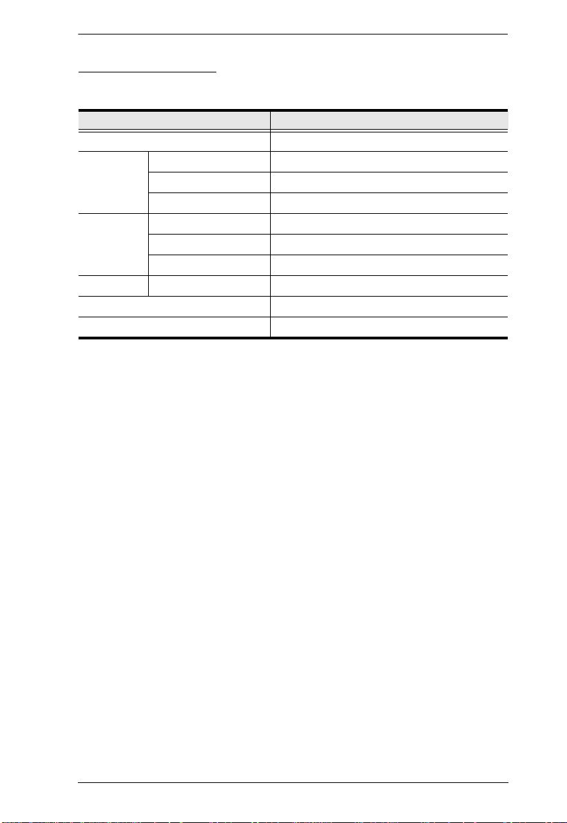
Components
Front View
2
1
5
3
6
7
4
12
11
8
10
9
6

Chapter 1. Introduction
No. Component Description
1 Upper Handle Pull to slide the LCD module out; push to slide it in.
2 LCD Module After sliding the LCD module out, flip up the cover to access
3 LCD Controls The buttons to control the position and picture settings of the
4 LCD On / Off
Button
5Port Selection
Buttons and LED
6 Keyboard Module Standard 105-key keyboard
7 Touchpad Standard mouse touchpad
8 USB Port The USB port is available to connect a USB peripheral
9 Power LED Lights (green) to indicate that the unit is receiving power.
10 Rack Mounting
Tabs
11 Lock LEDs The Num Lock, Caps Lock, Scroll Lock LEDs are located
12 Reset Switch Located to the right of the Lock LEDs. Press this recessed
See Operating Precautions, page 15, for details on sliding
the console in and out
the LCD display.
LCD display are located here. See page 16, for details.
Push this button to turn the LCD monitor on and off. The
button lights when the LCD monitor is off.
Note: The light indicates that only the monitor is off, not the
attached KVM switch.
To access a Port on the currently selected Station press its
corresponding port selection button. Indicator LEDs are built
into the switches:
-An On Line LED light to indicate that the computer attached
to its corresponding port is up and running.
-A Selection LED light to indicate which port has the KVM
focus.
device (flash drive, CD-ROM drive, etc.) to the console, or a
USB mouse for users who prefer to use an external mouse.
Rack mounting tabs are located at each corner of the unit.
here.
switch in with a thin object to perform a system reset.
7
RM-KB-LCD17KVMHD User Manual
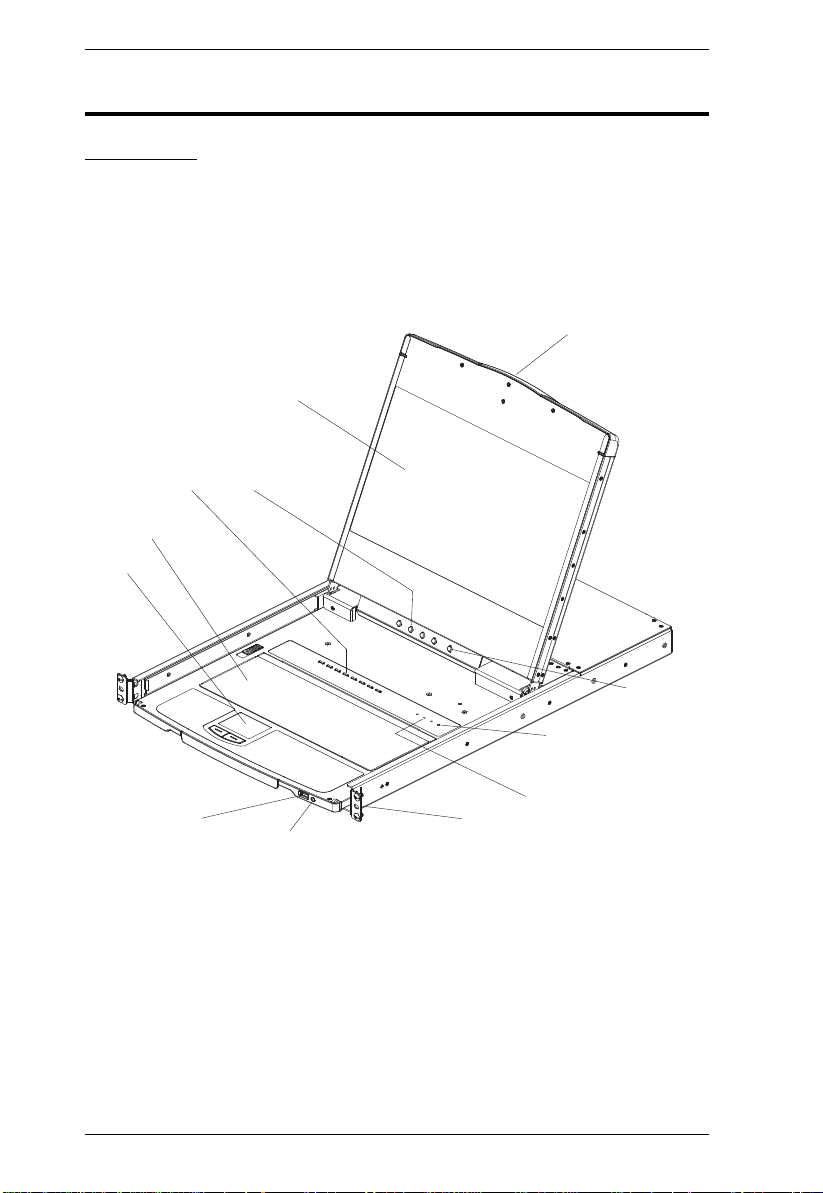
Rear View
1 2 3 4
5
No. Component Description
1 Power Socket This is a standard 3 prong AC power socket. The power cord
2 Power Switch This is a standard rocker switch that powers the RM-KB-
3 External
Console Section
4 KVM Port
Section
5 Grounding
Te rm i n al
from an AC source plugs in here.
LCD17KVMHD on and off.
For flexibility and convenience, the RM-KB-LCD17KVMHD
supports an independent, external, KVM console. The
external console's USB keyboard and mouse, DVI, or
HDMI monitor, and audio cables plug in here.
The custom KVM cable supplied with the package for linking
the RM-KB-LCD17KVMHD to a computer or switch plugs in
here. An additional HDMI and DVI port are provided.
The grounding wire (used to ground the unit) attaches here.
8
Chapter 2
1. Important safety information regarding the placement of this device is
provided in Safety Instructions. Please review it before proceeding.
2. Make sure that power to all the devices you will be connecting up has
been turned off. You must unplug the power cords of any computers
that have the Keyboard Power On function.
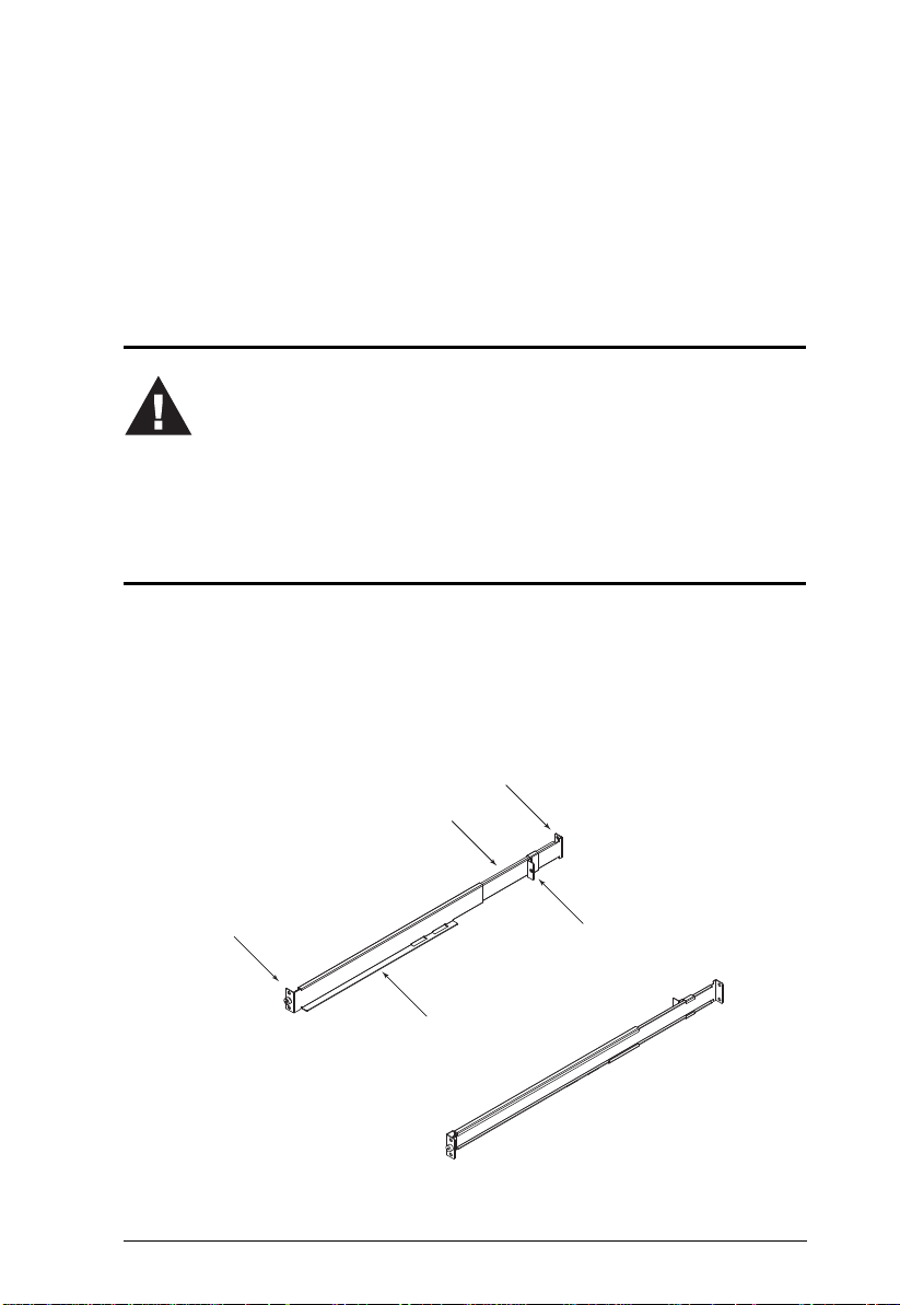
Rear Attachment
Sliding Bracket
Support
Flange
Slide Bar
Rear Flange
Front Flange
LEFT
RAIL
RIGHT
Hardware Setup
Before you Begin
Rack Mounting
1. Loosen ground screw prior to mounting. When unit is fully installed,
tighten ground screw.
2. Attach the left and right mounting rails to the inside of the rack. The flange
that supports the unit will be to the inside.
9
RM-KB-LCD17KVMHD User Manual
a) Screw the front flanges to the rack first.
b) Slide the bars with the rear flanges toward the rack until the flanges
make contact with the rack, then screw the rear flanges to the rack.
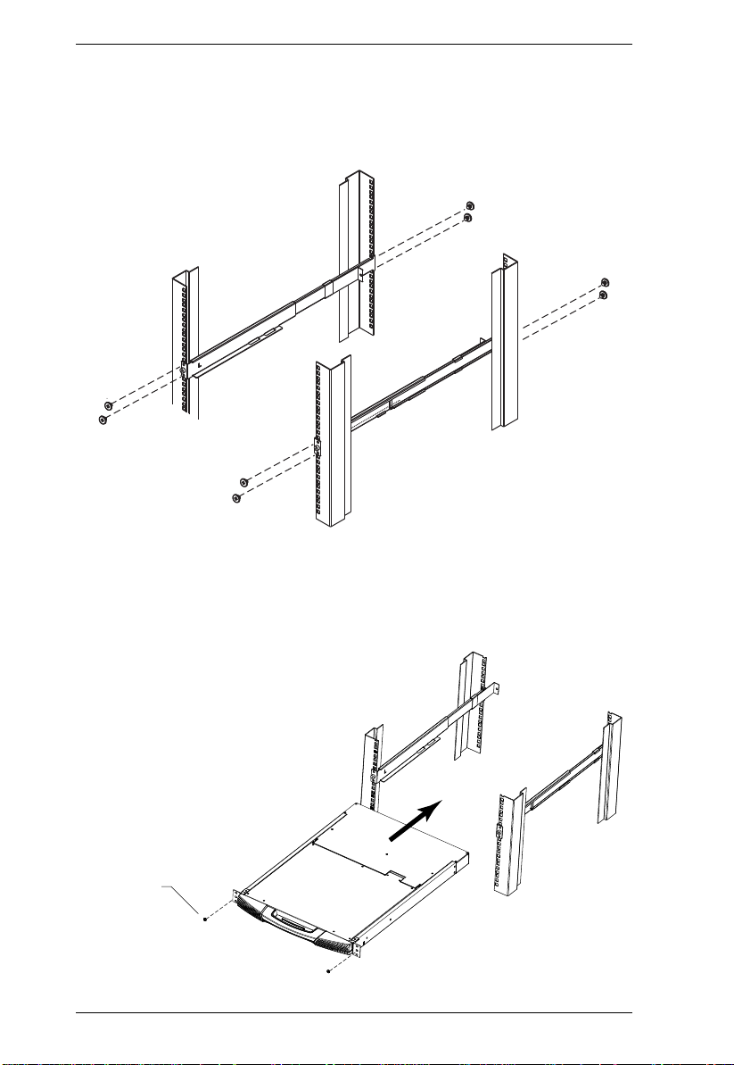
3. Slide the RM-KB-LCD17KVMHD onto the support flanges. Use the
screws supplied with this package to loosely attach the front of the RMKB-LCD17KVMHD to the front of the rack (only tighten the screws part
way).
Phillips I head
M4L6
10
Chapter 2. Hardware Setup
Phillips I head
M4L6
4. Slide the rear attachment sliding brackets along the slide bars until they
contact the rear of the RM-KB-LCD17KVMHD, then use the screws
supplied with this package to attach the bars to the rear of the RM-KBLCD17KVMHD (tighten the screws all the way).
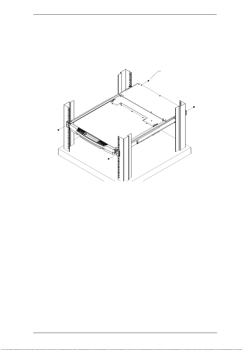
5. Slide the RM-KB-LCD17KVMHD open and closed a couple of times to
be sure that it is properly aligned and operating smoothly.
6. After determining that the RM-KB-LCD17KVMHD is lined up and
operating correctly, finish by fully tightening the front attachment screws
inserted in Step 3.
11

RM-KB-LCD17KVMHD User Manual
Connecting Up
Refer to the example installation diagram as you perform the following steps:
1. Plug the USB; then DVI or HDMI, and audio connectors of a KVM
cable (either supplied with the unit, or purchased separately, see Operating
Systems) into the CPU port on the rear of the RM-KB-LCD17KVMHD.
2. Plug the keyboard, monitor, mouse of the KVM cable into their respective
ports in the Console Section of a KVM switch or computer.
3. If you are installing an external console, plug your keyboard, monitor,
mouse into their respective ports in the Console Section of the RM-KBLCD17KVMHD.
Note: The RM-KB-LCD17KVMHD supports an HDMI (or DVI w/adapter)
external console monitor, but only one video signal (DVI-D
or HDMI) can be displayed at a time. The DVI monitor will display
a DVI-D signal only.
4. Plug the RM-KB-LCD17KVMHD’s power cord into the RM-KBLCD17KVMHD's power socket and into a power source.
5. Power up your KVM installation.
6. Turn on the power to LCD Console.
12
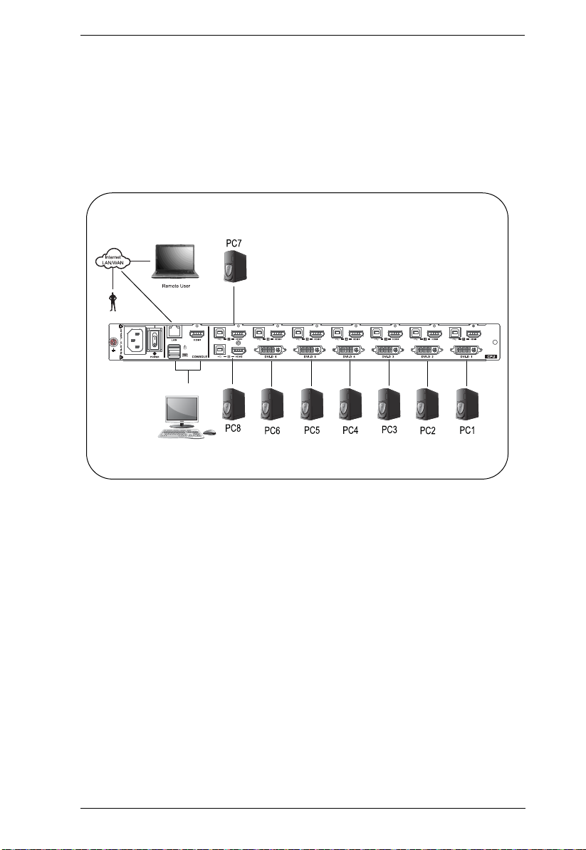
Installation Diagram
HDMI
Chapter 2. Hardware Setup
13

RM-KB-LCD17KVMHD User Manual
This Page Intentionally Left Blank
14
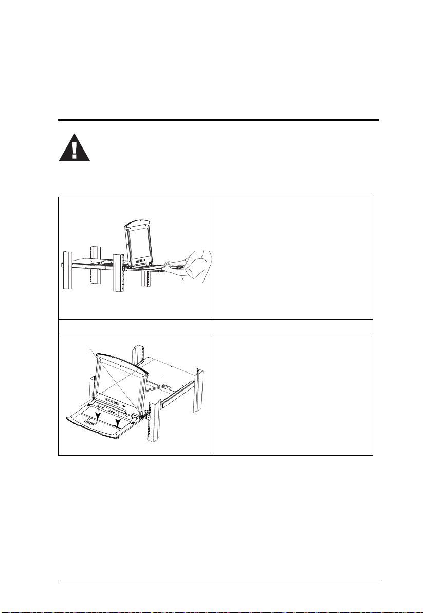
Operating Precautions
The maximum load bearing capacity of the keyboard module is 66 lbs.
(30 kg) Failure to heed the information below can result in damage to
the keyboard module.
Chapter 3
Operation
Right!
Rest your hands and arms lightly on the
keyboard module as you work.
Wrong!
DO NOT lean your body weight on the
keyboard module.
DO NOT place heavy objects on the
keyboard module.
15
RM-KB-LCD17KVMHD User Manual
LCD OSD Configuration
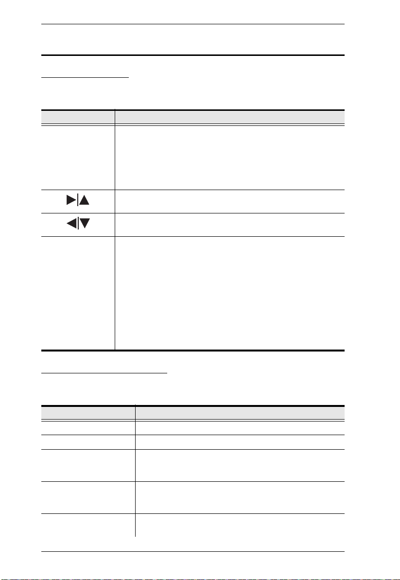
The LCD Buttons
The LCD OSD allows you to set up and configure the LCD display. Four
buttons are used to perform the configuration, as described in the table, below:
Button Function
MENU
EXIT
When you have not entered the LCD OSD Menu function,
pressing this button invokes the Menu function, and brings up
the Main Menu.
When you have entered the LCD OSD Menu function, and
have reached a setting choice with the navigation buttons,
pressing this button brings up its adjustment screen.
When navigating through the menus, this button moves you Right
or Up. When making an adjustment, it increases the value.
When navigating through the menus, this button moves you Left
or Down. When making an adjustment, it decreases the value.
When you have not entered the LCD OSD Menu function,
pressing this button performs an auto adjustment. An auto
adjustment automatically configures all the settings for the
LCD panel to what the OSD considers their optimum values to
be.
When you have entered the LCD OSD Menu function, pressing
this button exits the current menu and returns you to the
previous menu. Use it to leave an adjustment menu when you
are satisfied with the adjustment you made.
When you are at the Main Menu, pressing this button exits the
LCD OSD.
The Adjustment Settings
An explanation of the LED OSD adjustment settings is given in the table
below:
Setting Explanation
Brightness Adjusts the background black level of the screen image.
Contrast Adjusts the foreground white level of the screen image.
Phase If pixel jitter or horizontal line noise is visible on the display,
Clock If vertical banding is visible on the display, your LED may
H-Position Positions the display area on the LED panel horizontally
16
your LED may have the wrong phase setting. Adjust the
phase setting to eliminate these problems.
have the wrong clock setting. Adjust the clock setting to
eliminate vertical banding.
(moves the display area left or right).
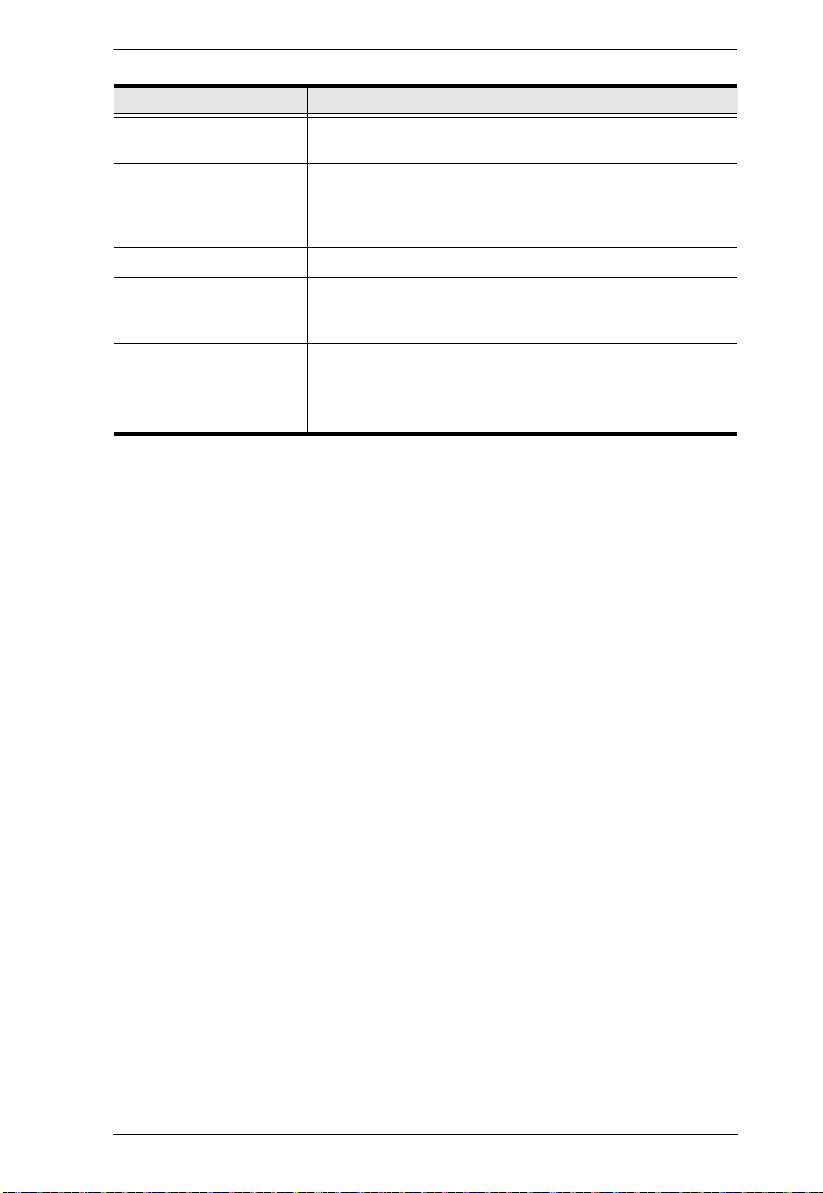
Chapter 3. Operation
Setting Explanation
V-Position Positions the display area on the LED panel vertically
Color Temperature Adjusts the color quality of the display. You can adjust the
Language Selects the language that the OSD displays its menus in.
OSD Duration Lets you set the amount of time the OSD displays on the
Reset Resets the adjustments on all menus and submenus to
(moves the display area up or down).
warmth value, color balance, etc. The Adjust Color
selection has a further submenu that lets you fine tune the
RGB values.
screen. If there is no input for the amount of time you
choose, the OSD display turns off.
their factory default settings.
Note: The Language setting does not return to the factory
default, but remains at the one that you have set it to.
17

RM-KB-LCD17KVMHD User Manual
Hot Plugging
The RM-KB-LCD17KVMHD supports hot plugging – components can be
removed and added to the computer by unplugging their cables from the ports
without the need to shut down the RM-KB-LCD17KVMHD.
Powering Off and Restarting
If it becomes necessary to Power Off the RM-KB-LCD17KVMHD (to upgrade
the firmware, for example), simply turn off the power to the unit using the rear
panel power switch. To restart the RM-KB-LCD17KVMHD, turn the rear
panel power switch back on.
Port Selection
The RM-KB-LCD17KVMHD provides two port selection methods to access
the computers on the installation: Manual and an OSD menu system. Manual
port switching is discussed below. See Chapter 4, On Screen Display (OSD)
Operation and Chapter 5, Keyboard Port Operation for more information.
USB Peripheral Devices
The front USB port is available to connect a USB peripheral device (flash
drive, CD-ROM drive, printer, etc.) to the RM-KB-LCD17KVMHD. Any
computer connected to the RM-KB-LCD17KVMHD can access the USB
peripheral on a one-at-a-time basis.
The USB peripheral device is automatically detected on target computers when
switching ports on the RM-KB-LCD17KVMHD. For example, when
switching from a computer connected to port 1 to a computer connected to port
2, the peripheral device automatically disconnects from the computer on port 1
and connects to the computer on port 2.
18
 Loading...