

Middle Atlantic Products DWR, DWR-10-17/22, DWR-21-17/22, DWR-24-17/22/26/32, DWR-12-17/22/26/32 Instruction Sheet
...
Instruction Sheet
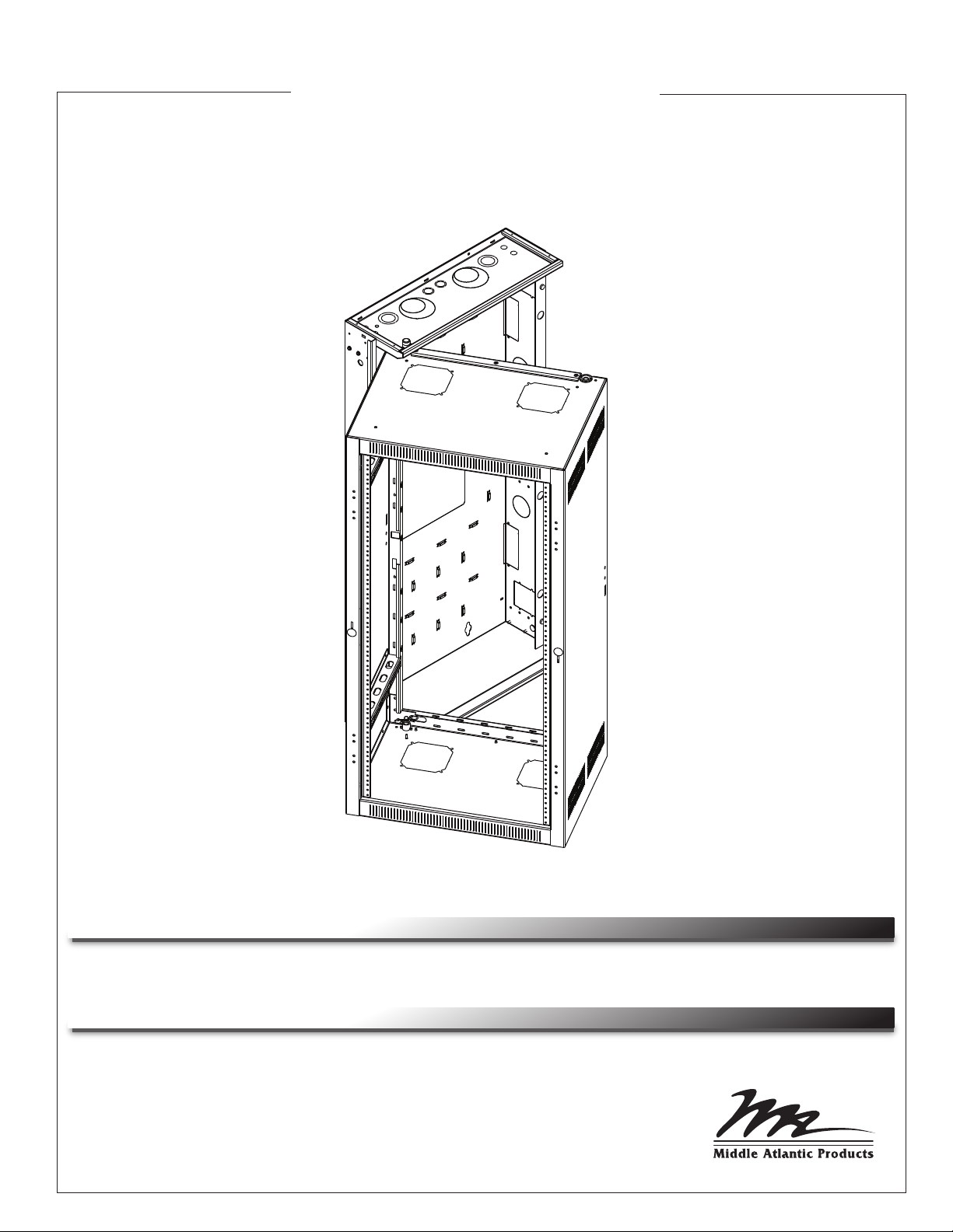
DWR SERIES
SECTIONAL WALL MOUNT RACK
THANK YOU
Thank you for purchasing the DWR Series Sectional Wall Rack. Please read these instructions
thoroughly before installing and assembling this product.
PRODUCT FEATURES
TM
• Tool-Free Quick-Mount
section to backpan
• Zero Clearance Latch (Optional) allows side-by-side or interior corner
mounting
• Wall mount sectional cabinet provides superior cable management
system allows easy, one person mounting of center
I-00065 Rev Q

IMPORTANT SAFETY INSTRUCTIONS
• Read these instructions.
• Keep these instructions.
• Heed all warnings.
• Follow all instructions.
• Clean only with dry cloth.
• Only use attachments/accessories specified by the manufacturer.
WARNING! Failure to read, understand and follow the following information can result in serious personal injury, damage to the
!
equipment or voiding of the warranty.
CAUTION: All installation and assembly steps must be performed by qualified personnel.
!
CAUTION: Ensure that the wall/floor has a structural load capacity that will support the weight of the cabinet fully loaded with
!
equipment.
CAUTION: Some parts of the enclosure system may not be effectively bonded to the Protective Earth Terminal (PET). If these parts
!
need to be bonded to the PET it should be done in accordance with Article 250 of the National Electrical Code.
CAUTION: Power cord(s), for fans or other accessories, need to be secured to ensure that they are routed away from pinch points
!
and moving parts.
CAUTION: Do not attempt to unload or move the enclosures alone. Make sure to have sufficient amount of personnel and
!
equipment to safely move this product.
DANGER HAZARDOUS VOLTAGE
The lightning flash with the arrowhead symbol, within an equilateral
triangle is intended to alert the user to the presence of uninsulated
dangerous voltage within the product’s enclosure that may be of
sufficient magnitude to constitute a risk of electric shock to persons.
CAUTION
The exclamation point within an equilateral triangle is intended to
alert the user to the presence of important operating and maintenance
(servicing) instructions in the literature accompanying the appliance.
CAUTION: The following parts are not effectively bonded to the protective earth terminal: Rackrails, lace bars, Lever Lock™,
!
shelving, baffles, blank panels, fan kits, and cable management equipment. If any part needs to be bonded to the protective earth
terminal it shall be done in accordance with Article 250 of the National Electrical Code.
SEISMIC COMPLIANCE: AN ENGINEERED SYSTEM IS VITAL TO ACHIEVE SEISMIC RATING REQUIREMENTS.
!
A LICENSED PROFESSIONAL ENGINEER MUST APPROVE THE TYPE OF FASTENERS FOR THE WALL
WHERE THE RACK WILL BE MOUNTED. BRACED ACCORDING TO SPECIFICATIONS SET FORTH BY
!
LICENSED ARCHITECTS AND ENGINEERS, THE MIDDLE ATLANTIC PRODUCTS RACK/ENCLOSURE YOU
PURCHASED IS CAPABLE OF SUSTAINING A PHENOMENAL LATERAL LOAD OF HIGH IMPORTANCE
EQUIPMENT WITH THE FRONT RAILS FILLED TO A MAXIMUM CAPACITY OF 140 LBS.
CAUTION: TO REDUCE THE RISK OF PERSONAL INJURY AND CONFORM TO THE UL LISTING THESE
!
MOUNTING INSTRUCTIONS MUST BE FOLLOWED AND PROPER WEIGHT CAPACITY MUST BE
OBSERVED (SEE CHART BELOW). AS A GENERAL RULE, HEAVIER EQUIPMENT SHOULD BE PLACED
TOWARDS THE BOTTOM OF THE RACK.
MAXIMUM WEIGHT CAPACITY# OF MOUNTING HOLESPART NUMBER
DWR-10-17/22
DWR-12-17/22/26/32
DWR-16-17/22
DWR-18-17/22/26/32
DWR-21-17/22
DWR-24-17/22/26/32
DWR-35-17/22/26
4
4
4
4
5
5
6
200 lbs.
200 lbs.
200 lbs.
250 lbs.
250 lbs.
300 lbs.
300 lbs.
Page 2
INSTRUCTIONS IMPORTAANTES SUR LA SÉCURITÉ
• Lisez ces instructions.
• Conservez ces instructions.
• Respectez tous les avertissements.
• Suivez toutes les instructions.
• Nettoyer avec un chiffon sec.
• Ne utilisez que des fixations / accessoires spécifiés par le fabricant.
ATTENTION! Ne pas lire, comprendre et suivre les informations suivantes peut entraîner des blessures graves, des dommages à la
!
l'équipement ou de la nullité de la garantie.
ATTENTION: Toutes installation et de montage étapes doivent être effectuées par du personnel qualifié.
!
ATTENTION: Se assurer que le mur / sol a une capacité de charge structurelle qui pourra supporter le poids de l'armoire
!
pleine charge avec équipement.
ATTENTION: Certaines parties du système d'enceinte ne peuvent pas être efficacement liés à la Terre de protection Terminal
!
(PET). Si ces pièces besoin d'être lié à l'animal, il doit être fait conformément à l'article 250 du Code national de l'électricité.
ATTENTION: Le cordon d'alimentation (s), pour les fans ou autres accessoires, doivent être fixés pour se assurer qu'ils sont
!
acheminés loin des points de pincement et des pièces en mouvement.
ATTENTION: Ne essayez pas de décharger ou déplacer les enceintes seul. Assurez-vous d'avoir suffisamment de
!
personnel et équipements pour déplacer ce produit en toute sécurité.
DANGER HAUTE TENSION
L'éclair avec le symbole de flèche dans un triangle équilatéral est
destiné à alerter l'utilisateur de la présence d'une tension dangereuse
non isolée dans l'enceinte du produit qui peut être d'une ampleur
suffisante pour constituer un risque de choc électrique pour les
personnes.
ATTENTION
Le point d'exclamation dans un triangle équilatéral est destiné à
alerter l'utilisateur de la présence d'importants instructions d’opération
et de maintenance (entretien) dans la documentation accompagnant
l'appareil.
ATTENTION: Les pièces suivantes ne sont pas effectivement liés à la borne de terre de protection: crémaillères, aiguilles,
!
barres de dentelle, Lever Lock™, étagères, des chicanes, des panneaux vierges, kits de ventilateur, et l'équipement de gestion
des câbles. Si une partie doit être lié à la borne de terre de protection il doit être fait conformément à l'article 250 du Code
national de l'électricité.
RESPECT SISMIQUE: UN SYSTÈME CONÇU EST INDISPENSABLE POUR ATTEINDRE EXIGENCES DE
!
NOTATION SISMIQUES. UN INGÉNIEUR AGRÉÉ DOIT APPROUVER LE TYPE D'ATTACHES POUR LE MUR
OÙ LA GRILLE SERA MONTÉ. HAUBANÉE SELON LES SPÉCIFICATIONS ÉNONCÉES PAR ARCHITECTES
!
AGRÉÉS ET DES INGÉNIEURS, LA MIDDLE ATLANTIC PRODUCTS RACK / ENCEINTE VOUS AVEZ ACHETÉ
EST CAPABLE DE SOUTENIR UNE CHARGE LATÉRALE PHÉNOMÉNALE DE ÉQUIPEMENT DE HAUTE
IMPORTANCE AVEC LES RAILS DE FRONT REMPLIS À UNE CAPACITÉ MAXIMALE DE 63.5 KG (140 LBS).
ATTENTION: POUR RÉDUIRE LE RISQUE DE BLESSURES ET CONFORME AU UL INSCRIPTION DE CES
!
INSTRUCTIONS DE MONTAGE DOIVENT SUIVRE ET BONNE POIDS CAPACITÉ DOIT ÊTRE OBSERVÉE
(VOIR TABLEAU CI-DESSOUS ) . EN REGLE GENERALE , ÉQUIPEMENT PLACER LES PLUS LOURDS VERS
LE BAS DE LA GRILLE.
CAPACITÉ DE CHARGE MAXIMALE# MONTAGE DE TROUSNUMÉRO DE PARTIE
DWR-10-17/22
DWR-12-17/22/26/32
DWR-16-17/22
DWR-18-17/22/26/32
DWR-21-17/22
DWR-24-17/22/26/32
DWR-35-17/22/26
4
4
4
4
5
5
6
90.7 kg (200 lbs.)
90.7 kg (200 lbs.)
90.7 kg (200 lbs.)
113.3 kg (250 lbs.)
113.3 kg (250 lbs.)
136 kg (300 lbs.)
136 kg (300 lbs.)
Page 3
OVERALL DIMENSIONS
Width: 23.4"
Height: 10 RU - 35 RU
Depths: 17", 22", 26"* and 32"*
* Available for certain heights only
INSTALLATION
1. Separate backpan from center section and determine hinge side.
NOTE: DWR center section can be opened from left-to-right or vice versa depending on how backpan
is installed.
THE BACKPAN MUST BE INSTALLED PLUMB AND LEVEL FOR PROPER OPERATION.
!
LA PLAQUE PROFILÉE DOIT ETRE APLOMB ET DE NIVEAU POUR UN FONCTIONNEMENT
!
NOTE: Ensure the backpan is screwed to the studs. All DWRs may be mounted using the method
outlined in step 2, and DWRs up to 26” overall depth may also be mounted on concrete walls. You
can install 32” overall depth DWRs as outlined in step 2 only.
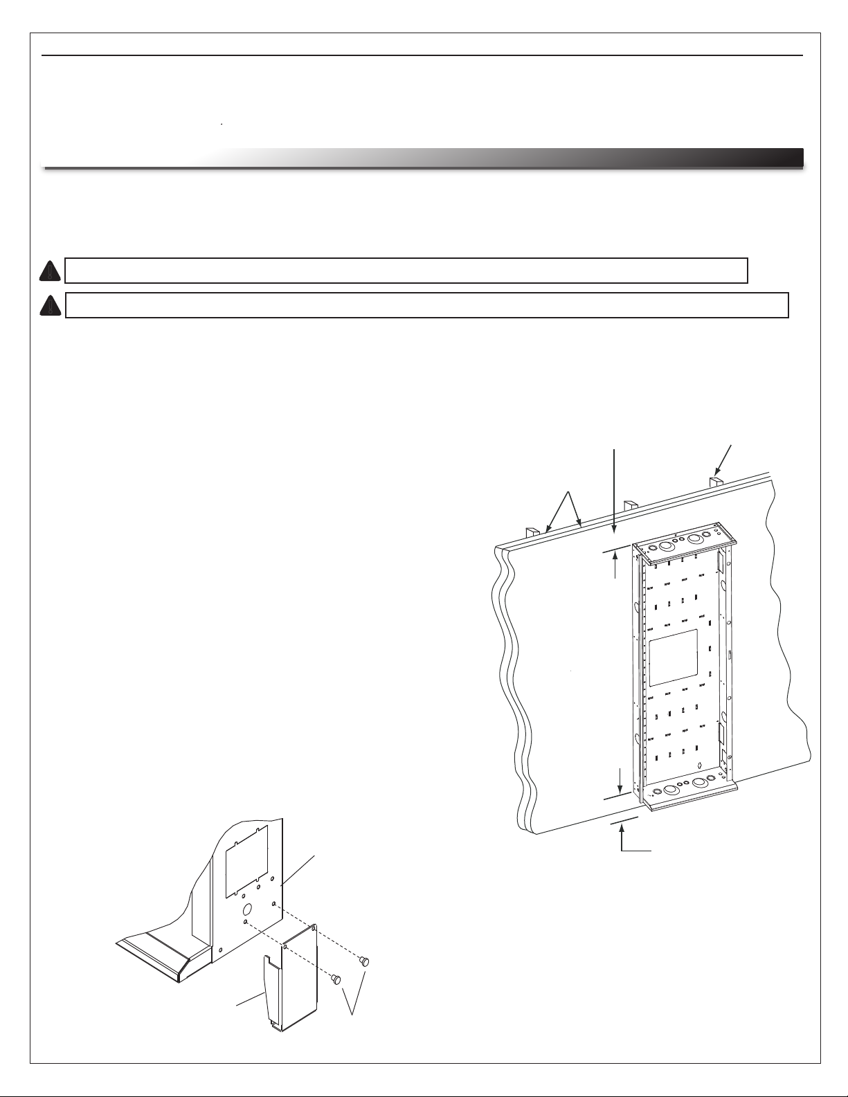
2. Mount backpan to wall (a minimum of 4" clearance
top and bottom is required) using 3/8" dia. lag bolts with
a minimum length of 2" and standard flat washers.
(FIGURE A)
NOTE:
• The standard flat washers must be installed under
the lag bolt heads. Refer to the chart on the previous
page for the number of mounting holes required. All
mounting holes must be used.
• Feet are included with the 24 and 35 rackspace
DWRs only. These feet are to be used when
mounting in close proximity to the floor (4”). The
feet help reduce the shear weight off of the mounting
hardware that is used to hold the rack to the wall
when a significant amount of weight is loaded in the
rack.
3. To install feet, remove screws on bottom of backpan
(both sides) and reattach with feet in position. (FIGURE B)
MIN. 4” CLEARANCE
REQUIRED
1/2” DRYWALL
STUD
FIGURE B
FOOT
BACKPAN
SCREWS
MIN. 4” CLEARANCE
REQUIRED
FIGURE A
Page 4
 Loading...