

Middle Atlantic Products DWR, DWR-16-17/22, DWR-10-17/22, DWR-18-17/22/26/32, DWR-24-17/22/26/32 Instruction Sheet
...
Instruction Sheet
DWR SERIES
SECTIONAL WALL MOUNT RACK
U
R
C US
LISTED
L
THANK YOU
Thank you for purchasing the DWR Series Sectional Wall Rack. Please read these instructions
thoroughly before installing / assembling this product.
PRODUCT FEATURES
- Tool-Free Quick-Mount
section to backpan
- Zero Clearance Latch (Optional) allows side-by-side or interior corner
mounting
- Wall mount sectional cabinet provides superior cable management
TM
system allows easy, one person mounting of center
I-00065 Rev M

IMPORTANT SAFETY INSTRUCTIONS
• Read these instructions.
• Keep these instructions.
• Heed all warnings.
• Follow all instructions.
• Clean only with dry cloth.
• Only use attachments/accessories specified by the manufacturer.
WARNING: A WARNING ALERTS YOU TO A SITUATION
!
THAT COULD RESULT IN SERIOUS PERSONAL INJURY
OR DEATH.
CAUTION: A CAUTION ALERTS YOU TO A SITUATION
!
THAT MAY RESULT IN MINOR PERSONAL INJURY OR
DAMAGE TO THE PRODUCT AND / OR PROPERTY.
NOTE: A NOTE IS USED TO HIGHLIGHT PROCEDURES
PERTAINING TO THE INSTALLATION, OPERATION OR
MAINTENANCE OF THE PRODUCT.
IMPORTANT WARNINGS AND CAUTIONS!
WARNING! Failure to read, understand and follow the following information can result in serious personal injury, damage to the
!
equipment or voiding of the warranty.
CAUTION: All installation and assembly steps must be performed by qualified personnel.
!
CAUTION: Ensure that the wall/floor has a structural load capacity that will support the weight of the cabinet fully loaded with
!
equipment.
CAUTION: Some parts of the enclosure system may not be effectively bonded to the Protective Earth Terminal (PET). If these parts
!
need to be bonded to the PET it should be done in accordance with Article 250 of the National Electrical Code.
CAUTION: Power cord(s), for fans or other accessories, need to be secured to ensure that they are routed away from pinch points
!
and moving parts.
CAUTION: Do not attempt to unload or move the enclosures alone. Make sure to have sufficient amount of personnel and
!
equipment to safely move this product.
CAUTION: The following parts are not effectively bonded to the protective earth terminal: Rackrails, lace bars, Lever Lock™,
!
shelving, baffles, blank panels, and cable management equipment. If any part needs to be bonded to the protective earth terminal
it shall be done in accordance with Article 250 of the National Electrical Code.
SEISMIC COMPLIANCE: AN ENGINEERED SYSTEM IS VITAL TO ACHIEVE SEISMIC RATING REQUIREMENTS.
!
A LICENSED PROFESSIONAL ENGINEER MUST APPROVE THE TYPE OF FASTENERS FOR THE WALL
WHERE THE RACK WILL BE MOUNTED. BRACED ACCORDING TO SPECIFICATIONS SET FORTH BY
LICENSED ARCHITECTS AND ENGINEERS, THE MIDDLE ATLANTIC PRODUCTS RACK/ENCLOSURE YOU
PURCHASED IS CAPABLE OF SUSTAINING A PHENOMENAL LATERAL LOAD OF HIGH IMPORTANCE
EQUIPMENT WITH THE FRONT RAILS FILLED TO A MAXIMUM CAPACITY OF 140 LBS.
CAUTION: TO REDUCE THE RISK OF PERSONAL INJURY AND CONFORM TO THE UL LISTING THESE
!
MOUNTING INSTRUCTIONS MUST BE FOLLOWED AND PROPER WEIGHT CAPACITY MUST BE
OBSERVED (SEE CHART BELOW). AS A GENERAL RULE, HEAVIER EQUIPMENT SHOULD BE PLACED
TOWARDS THE BOTTOM OF THE RACK.
MAXIMUM WEIGHT CAPACITY# OF MOUNTING HOLESPART NUMBER
DWR-10-17/22
DWR-12-17/22/26/32
DWR-16-17/22
DWR-18-17/22/26/32
DWR-21-17/22
DWR-24-17/22/26/32
DWR-35-17/22/26
4
4
4
4
5
5
6
200 lbs.
200 lbs.
200 lbs.
250 lbs.
250 lbs.
300 lbs.
300 lbs.
OVERALL DIMENSIONS
Width: 23.4"
Height: 10 RU - 35 RU
Depths: 17", 22", 26"* and 32"*
* Available for certain heights only
Page 2
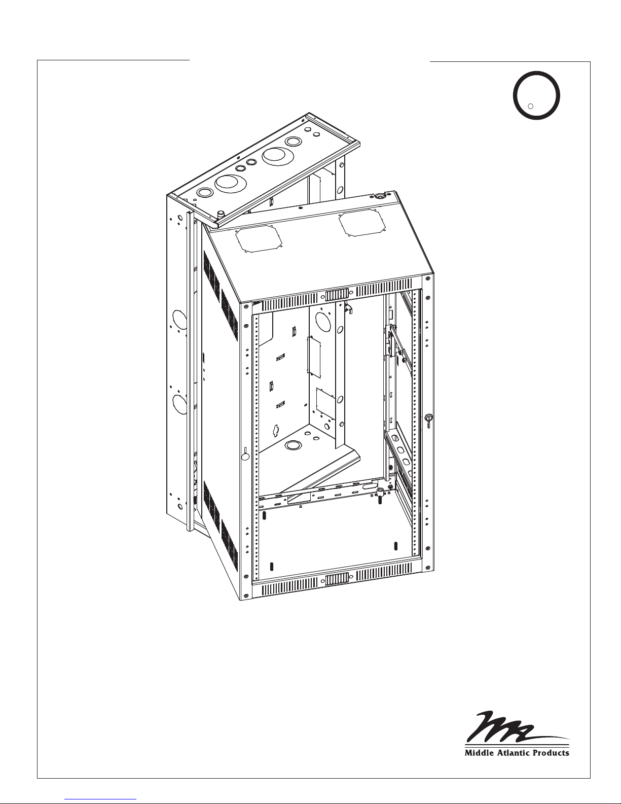
INSTALLATION
1) Separate backpan from center section and determine hinge side.
NOTE: DWR center section can be opened from left-to-right or vice versa depending on how backpan
is installed.
THE BACKPAN MUST BE INSTALLED PLUMB AND LEVEL FOR PROPER OPERATION.
!
NOTE: Ensure the wall to which the backpan will be mounted, consists of two (2) 3/4" plywood
screwed to the studs. All DWR’s may be mounted using the method outlined in step 2, and DWR’s
up to 26” overall depth may also be mounted on concrete walls. You can install 32” overall depth
DWR’s as outlined in step 2 only.
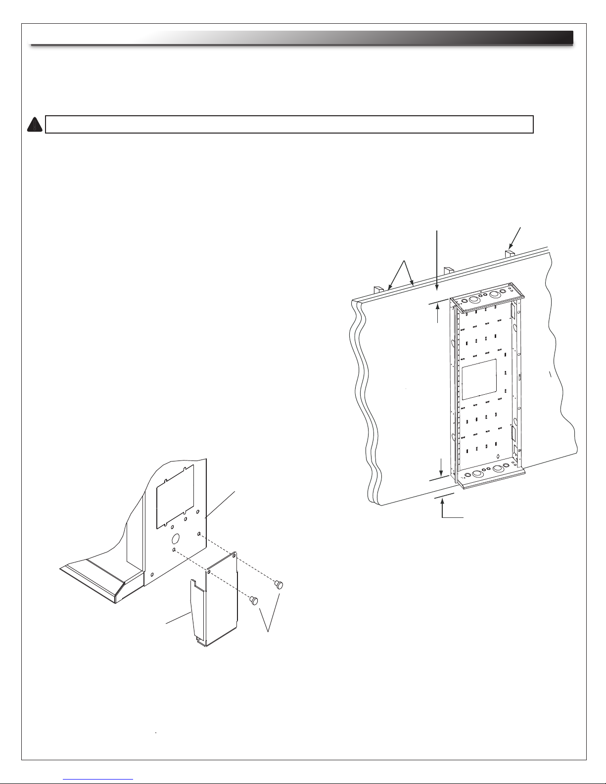
2) Mount backpan to wall (a minimum of 4" clearance
top and bottom is required) using 3/8" dia. lag bolts with
a minimum length of 1 1/2" and standard flat washers.
(FIGURE A)
NOTE: The standard flat washers must be installed under
the lag bolt heads. Refer to the chart on the previous
page for the number of mounting holes required. All
mounting holes must be used.
NOTE: Feet are included with the 24 and 35 rackspace
DWR’s only. These feet are to be used when
mounting in close proximity to the floor (4”). The
feet help reduce the shear weight off of the mounting
hardware that is used to hold the rack to the wall
when a significant amount of weight is loaded in the
rack.
3) To install feet, remove screws on bottom of backpan
(both sides) and reattach with feet in position. (FIGURE B)
BACKPAN
MIN. 4” CLEARANCE
REQUIRED
TWO (2)
3/4” PLYWOOD
STUD
FOOT
FIGURE B
MIN. 4” CLEARANCE
REQUIRED
FIGURE A
SCREWS
Page 3
 Loading...