

Page 1
Instruction Sheet
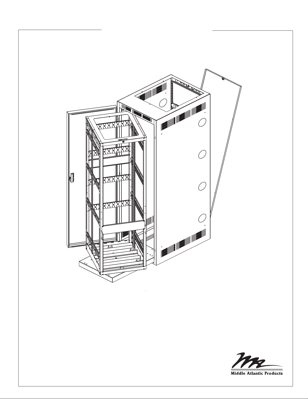
WR SERIES
Roll Out Rotating System In Steel
Host Enclosure
THANK YOU
Thank you for purchasing the WR Series. Please read these instructions thoroughly before
installing / assembling this product.
PRODUCT FEATURES
- Roll out, rotating system provides unrestricted access to equipment and cabling
- Rack rolls out without the need for tracks and stands
- Top options available to facilitate either Passive (Convection) or Active
(Forced Air Flow) thermal management
I-00099 Rev J
Page 2

IMPORTANT SAFETY INSTRUCTIONS / INSTRUCTIONS IMPORTAANTES SUR LA SÉCURITÉ
SAVE ALL INSTRUCTIONS / CONSERVER CES INSTRUCTIONS
DANGER HAZARDOUS VOLTAGE/DANGER HAUTE TENSION
The lightning flash with the arrowhead symbol, within an equilateral
triangle is intended to alert the user to the presence of uninsulated
dangerous voltage within the product’s enclosure that may be of
sufficient magnitude to constitute a risk of electric shock to persons.
L'éclair avec le symbole de flèche dans un triangle équilatéral est
destiné à alerter l'utilisateur de la présence d'une tension dangereuse
non isolée dans l'enceinte du produit qui peut être d'une ampleur
suffisante pour constituer un risque de choc électrique pour les
personnes.
WARNING: Failure to read, understand and follow the following information can result in
serious personal injury, damage to the equipment or voiding of the warranty.
AVERTISSEMENT: Ne pas lire, comprendre et suivre les informations
suivantes peut entraîner des blessures graves, des dommages à l'équipement
ou de la nullité de la garantie.
CAUTION: To avoid an unstable condition, place heavier components at the bottom of the
enclosure. When more than one component is placed in the enclosure, begin at the bottom
of the enclosure and place equipment at the lowest available point, evenly distribute weight
(horizontally) within the enclosure.
CAUTION/ATTENTION The exclamation point within an equilateral
triangle is intended to alert the user to the presence of important
operating and maintenance (servicing) instructions in the literature
accompanying the appliance.
Le point d'exclamation dans un triangle équilatéral est destiné à
alerter l'utilisateur de la présence d'importants instructions d’opération
et de maintenance (entretien) dans la documentation accompagnant
l'appareil.
Component weight should be distributed as follows:
• 1/2 of the total component weight (at a minimum) placed in the bottom third of the cabinet
• 1/4 of the total component weight (at a maximum) placed in the middle third of the cabinet
• 1/4 of the total component weight (at a maximum) placed in the top third of the cabinet
ATTENTION: Pour éviter un état instable, placez composants les plus lourds au
fond de l'enceinte. Lorsque plus d'un composant est placé dans la enceinte,
commencer par le bas de l'enceinte et placer l'équipement à la point le plus bas
disponible, de distribuer uniformément le poids (horizontalement) dans le enceinte.
Le poids des composants devrait être réparti comme suit:
• 1/2 du poids total de la composante (au minimum) placé dans le tiers inférieur de l'armoire
• 1/4 du poids total de la composante (au maximum) placé dans le tiers médian de l'armoire
• 1/4 du poids total de la composante (au maximum) placé dans le tiers supérieur de l'armoire
Page 2
Page 3
IMPORTANT SAFETY INSTRUCTIONS / INSTRUCTIONS IMPORTAANTES SUR LA SÉCURITÉ
CAUTION: All installation and assembly steps must be performed by qualified personnel.
ATTENTION: Toutes installation et de montage étapes doivent être effectuées par du
personnel qualifié.
CAUTION: Ensure that the floor has a structural load capacity that will support the weight of
the cabinet fully loaded with equipment.
ATTENTION: Veiller à ce que le sol a une capacité de charge structurelle qui supporter le
poids de le cabinet entièrement chargé avec l'équipement .
CAUTION: Some parts of the enclosure system may not be effectively bonded to the
Protective Earth Terminal (PET). If these parts need to be bonded to the PET it should be
done in accordance with Article 250 of the National Electrical Code.
ATTENTION: Certaines parties du système d'enceinte ne peut être efficacement liée à la
Terre de protection Terminal (PET). Si ces pièces doivent être collées au PET, il devrait
être fait conformément à l'article 250 du Code national de l'électricité.
CAUTION: Power cord(s), for fans or other accessories, need to be secured to ensure that
they are routed away from pinch points and moving parts.
ATTENTION: Le cordon d'alimentation (s), pour les fans ou autres accessoires, doivent être
fixé à veiller à ce que ils sont acheminés loin des points de pincement et des pièces mobiles.
Page 3
Page 4

IMPORTANT SAFETY INSTRUCTIONS / INSTRUCTIONS IMPORTAANTES SUR LA SÉCURITÉ
CAUTION: Use caution when moving the cabinets with casters installed. There is a
possibility of tilting. Always move cabinet over smooth floor surfaces and a short distance
only. The enclosure should only be moved by pushing on the front or rear of the cabinet. DO
NOT push from the side.
ATTENTION: Soyez prudent lors du déplacement des armoires à roulettes installées. Il se
agit d'un possibilité de basculement. Toujours déplacer l'armoire sur les surfaces lisses et à
une courte distance seulement. L'enceinte ne doit être déplacé en poussant sur le devant ou
à l'arrière de l'armoire. FAIRE PAS pousser de côté.
CAUTION: Do not attempt to unload or move the enclosures alone. Make sure to have
sufficient amount of personnel and equipment to safely move this product.
ATTENTION: Ne essayez pas de décharger ou déplacer les enceintes seul. Assurez-vous
d'avoir quantité suffisante de personnel et de matériel pour déplacer ce produit en toute
sécurité.
WARNING: When rotated and in the service position, do not push rack.
Rack must be returned to non-rotated position before pushing rack back into host
enclosure or death or serious injury can occur.
AVERTISSEMENT: Lorsque tourné et dans la position de service, ne pas pousser rack.
Rack doit être retourné à la position non-rotation avant de pousser en fond de rack hôte
ou la mort ou des blessures graves peuvent se produire.
SPECIFICATIONS
Heights: 24 RU to 44 RU (each RU = 1.75”)
Width: 24”
Depths: 26” and 36”
Max. Rollout: 25” and 35”
Load Ratings: 750 lbs. load rating
Added Weight (Loading): Total added weight should be distributed as follows:
• 1/2 of the total added weight (at a minimum) placed in the bottom third of the enclosure
• 1/4 of the total added weight (at a maximum) palced in the middle third of the enclosure
• 1/4 of the total added weight (at a maximum) placed in the top third of the enclosur
Page 4
Page 5

ASSEMBLY
Tools Needed: #2 Phillips Driver
NOTE: Use caution when opening and closing rack.
NOTE: Ensure the green Grounding/Bonding
cable has been disconnected at the quick
connect/disconnect before removing the
rack from the host enclosure.
1) Remove rack frame from host enclosure.
(See FIGURE A) To remove rack frame, first install
handles in the desired mounting hole locations.
2) Slide out the rack frame to end of track
(See FIGURE B).
3) Using handles and with foot placed at bottom of rack
frame, carefully tilt rack frame slightly forward and
remove from host enclosure (See FIGURE B)
HOST
ENCLOSURE
RACK
FRAME
KEYLOCK
LACER
BARS
4) Mount equipment into rack frame.
5) For proper cable management, adjust lacer bars on
HANDLES
FIGURE A
rack frame and host enclosure as needed.
NOTE: 1/2 of total equipment weight must be
NOTE: Floor must be level before mounting host
mounted in lower 1/3 of the rack.
enclosure.
6) Mount host enclosure to floor using the 4 mounting holes on bottom of enclosure. (See FIGURE C)
NOTE: Connect the green Grounding/Bonding cables to
each other at the quick connect/disconnect before installing
the rack into the host enclosure.
7) Once equipment is installed, guide rack and position
rear casters by aligning with guides of host enclosure.
Slide rack completely into the host enclosure and lock.
(See FIGURE B)
8) Lock rack in the closed position
using the keylock at top of the rack
MOUNTING
HOLES
frame. (See FIGURE A)
FIGURE B
Page 5
FIGURE C
Page 6

CABLE MANAGEMENT
PROPER METHOD OF FASTENING CABLES USING WIRE TIES
AND HOOK AND LOOP STRAPS (HINT - LEAVE THIS LOOSE)
NOTE: Determine in which direction the rack
frame will rotate before beginning cable management.
When lacing cables into the back of the host
enclosure, dressing should be done
while the rack frame is removed.
LACER
BAR
1) Remove the rack frame from the host enclosure.
2) Bring all wiring into the host enclosure rear
through either the bottom or top.
(See FIGURE D)
TIP: It is recommended that you leave about
8 to 10 extra feet of cable to allow rack
frame to fully extend and rotate.
3) Stand inside host enclosure and begin
fastening cables to the lacer bars on the rear
of the host enclosure.
4) At the rear of the host enclosure, select one
side of the lacer bars for signal cables,
and the opposite side for power cables
(See FIGURE E for reference). Lace the
cables vertically to the lacer bars starting
from either the top or the bottom of the host
enclosure.
FIGURE D
REAR OF
RACK FRAME
FASTEN CABLES
APPROXIMATELY
3” FROM END
REAR OF HOST
ENCLOSURE
5) Determine at which host enclosure lacer bar the cable
bundle will go to the rack frame from and fasten the cable
bundle to this point. (The extra 8 to 10 feet should start at
where the bundle is fastened to the host enclosure lacer
bar at the point where it will go to the rack frame)
6) Bring the rack frame to the front of the host enclosure
and pull the cable bundles into the rack frame. Slide the
rack frame into the host enclosure. Make sure that the
cables are free and clear when doing so.
7) Extend the rack frame and rotate as shown. (rotate the rack
frame in the predetermined direction)
8) Criscross the cable bundles from the host enclosure to the
rack frame and fasten to the lacer bars at the rear of the rack
frame. (See FIGURE E)
9) Ensure cable bundles that go from the host enclosure to the
rack frame are pulled tight.
Cable Management Tip: Tie cable bundles at least every 6" - 8".
This allows cable bundles to lay neatly together when the rack
frame is in the closed position.
SIGNAL
CABLES
FIGURE E
(TOP VIEW)
REAR
POWER CABLES
HOST ENCLOSURE
CRISSCROSS
CABLE BUNDLES
REAR
RACK FRAME
SHOWN ROTATED
GANGING CABINETS - REQUIRES MIDDLE ATLANTIC PRODUCTS MODEL # GANG-10 (SOLD SEPARATELY)
Page 6
Page 7

WARRANTY
Middle Atlantic Products (the "Company") warrants the WR Series Enclosure to be free from defects
in material or workmanship under normal use and conditions for the lifetime of the product.
The Company's entire liability to the purchaser, and the purchaser's (or any other party's) sole and
exclusive remedy, under this warranty shall be limited, at the Company's option, to either (a) return of
and refund of the price paid for, or (b) repair or replacement at the Company's factory of the products
purchased, or any part or parts thereof, which the Company has determined to be defective after
inspection thereof at the Company's factory.
This warranty does not cover damage due to acts of God, accident, misuse, abuse or negligence by
parties other than the Company, or any modification or alteration of the products. In addition, this
warranty does not cover damage due to improper handling, assembly, installation or maintenance.
THIS WARRANTY IS IN LIEU OF ALL OTHER WARRANTIES OF ANY KIND, EITHER EXPRESSED OR
IMPLIED, INCLUDING, BUT NOT LIMITED TO, IMPLIED WARRANTIES OF MERCHANTABILITY AND
FITNESS FOR A PARTICULAR PURPOSE.
TO THE MAXIMUM EXTENT PERMITTED BY APPLICABLE LAW, IN NO EVENT SHALL THE COMPANY
BE LIABLE FOR ANY SPECIAL, INCIDENTAL, INDIRECT, OR CONSEQUENTIAL DAMAGES
WHATSOEVER (INCLUDING, WITHOUT LIMITATION, DAMAGES FOR LOSS OF BUSINESS PROFITS,
BUSINESS INTERRUPTION OR ANY OTHER PECUNIARY LOSS) ARISING OUT OF THE USE OF THE
PRODUCTS PURCHASED, EVEN IF THE COMPANY HAS BEEN ADVISED OF THE POSSIBILITY OF
SUCH DAMAGES. THE COMPANY'S LIABILITY TO THE PURCHASER (OR ANY OTHER PARTY)
HEREUNDER, IF ANY, SHALL IN NO EVENT EXCEED THE PURCHASE PRICE OF THE PRODUCTS
PAID TO THE COMPANY.
Corporate Headquarters
Corporate Voice 973-839-1011 - Fax 973-839-1976
International Voice +1 973-839-8821 - Fax +1 973-839-4982
middleatlantic.com - info@middleatlantic.com
Middle Atlantic Canada
Voice 613-836-2501 - Fax 613-836-2690
middleatlantic.ca - customerservicecanada@middleatlantic.ca
Factory Distribution
USA: NJ - CA - IL Canada: ON - BC
At Middle Atlantic Products we are always listening. Your comments are welcome.
Middle Atlantic Products is an ISO 9001 and ISO 14001 Registered Company.
Page 7
30% Recycled Paper
 Loading...