

Page 1
Instruction Sheet
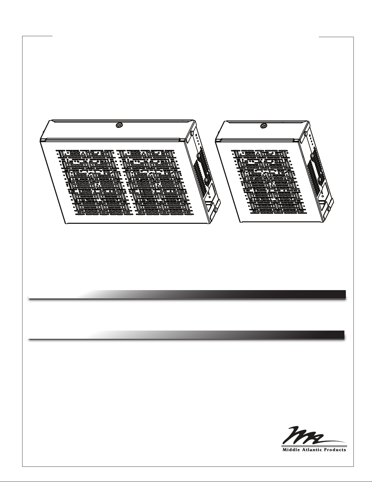
Universal TechBox™ Series
UTB-A2-14 / UTB-HR-A2-14
THANK YOU
Thank you for purchasing a Universal TechBox™ UTB-A2-14 / UTB-HR-A2-14. Please read
these instructions thoroughly before installing this product.
PRODUCT FEATURES
• Convenient system protects equipment and may be mounted underneath table.
• Accommodates both 1 and 2 RU configurations.
• Available in full- and half-rack models.
• Lock mechanism for added security.
• Universal mounting system cutout on the bottom designed to accommodate small devices.
• Weight rated to 35 lbs. of maximum capacity.
NOTE: These instructions apply to both UTB-A2-14 (full-rack) and UTB-HR-A2-14 (half-rack
models).
I-00772 Rev -
Page 2
IMPORTANT SAFETY INSTRUCTIONS / INSTRUCTIONS IMPORTAANTES SUR LA SÉCURITÉ
WARNING! Middle Atlantic Products, Inc. electrical
!
systems conform to and should be properly grounded in
compliance with requirements of the current National
Electrical Code or codes administered by local
authorities.
All electrical products may present a possible shock or fire
hazard if improperly installed or used. Middle Atlantic
Products, Inc. electrical products may bear the mark of a
Nationally Recognized Testing Laboratory (NRTL) and
should be installed in conformance with current local and/or
the National Electrical Code.
WARNING! Failure to read, understand and follow the
!
following information can result in serious personal injury,
damage to the equipment or voiding of the warranty. It is
the responsibility of the Installer/User to ensure
that this product is loaded according to specifications.
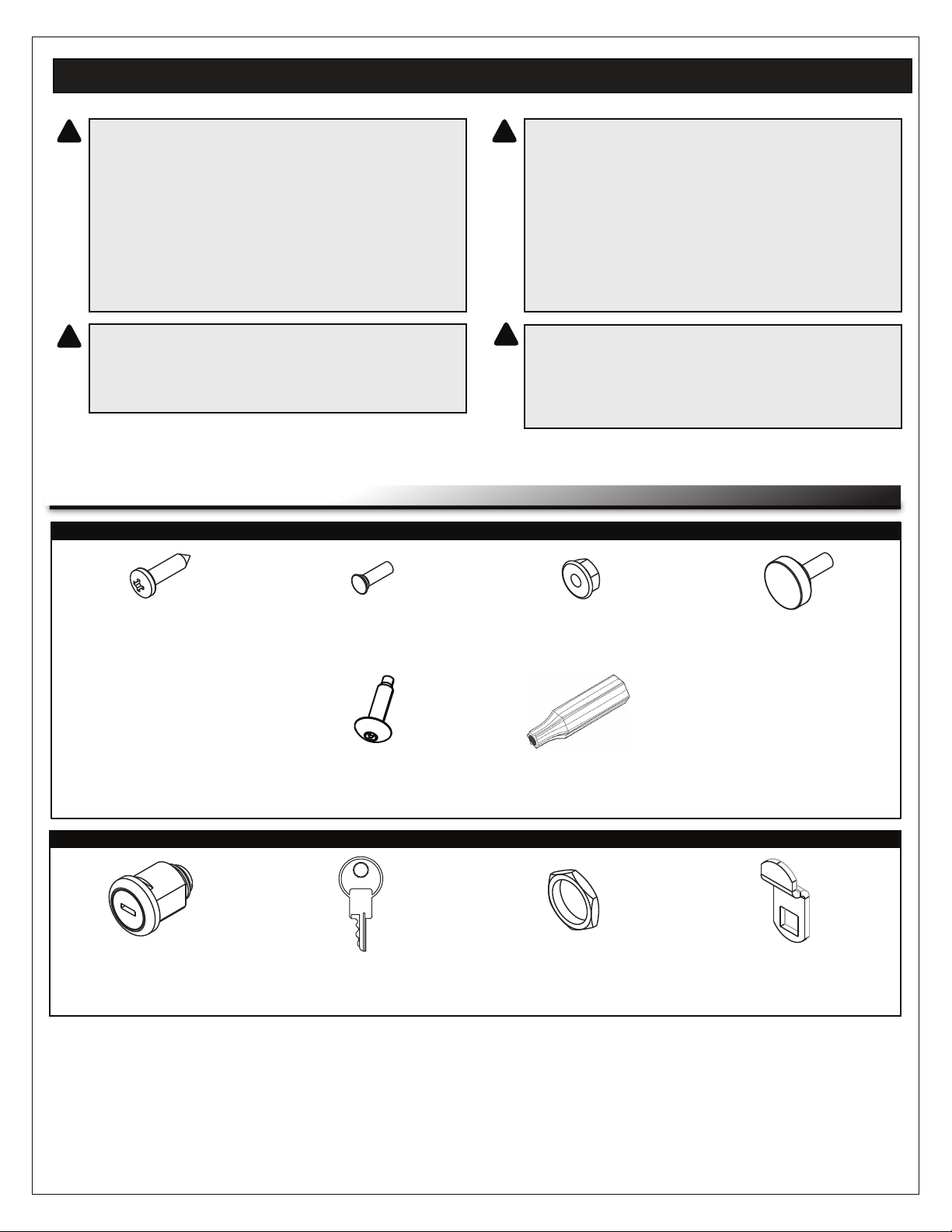
HARDWARE/ITEMS SUPPLIED
RACKRAIL AND BOX
AVERTISSEMENT! Middle Atlantic Products, Inc.
!
électrique systèmes conformes à devraient être mis à la
terre dans conformité avec les exigences de la National
actuelle ou comme les codes électrique administré par les
autorités locales autorités.
Tous les produits électriques peuvent présenter un choc ou
un incendie danger si elle est mal installé ou utilisé. Middle
Atlantic Products, Inc. produits électriques peuvent porter
la marque d'un Nationally Recognized Testing Laboratory
(NRTL) et doit être installé en conformité avec courant local
et/ou le National Electrical Code.
AVERTISSEMENT! Refus de lire, comprendre et suivre
!
la renseignements suivants peut traduire par de graves
blessures, des dommages à l'équipement ou invalider la
garantie. Il est la responsabilité de l'installateur / utilisateur
de s'assurer que ce produit est chargé conformément aux
spécifications.
10 x 3/4 Phil. Pan
Wood Screws (10x)
FACEPLATE LOCK
Faceplate Lock
Cylinder (2x)
10-32 x 5 PEM
Studs (5x)
10-32 x 3/4 Security
Screws (HTX, 4x)
Keys
(B399A-FD, 4x)
10-32 Hex Flange
Nuts (5x)
Security Screw Bit
(TBIT)
3/4-24 Faceplate Lock Nut
(7/8” Socket Req’d, 2x)
10-32 x 3/4 Thumb
Screws (8x)
Faceplate Lock
Cam (2x)
Page 2
Page 3
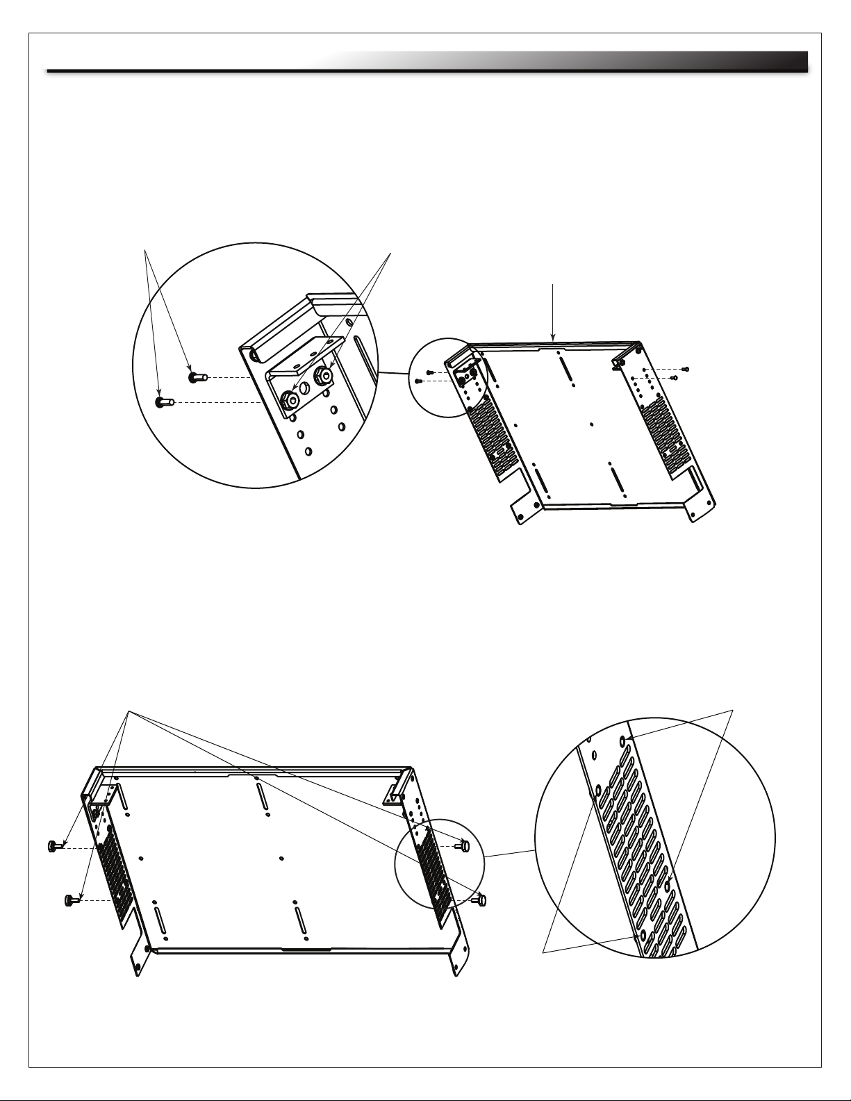
RACKRAIL AND THUMBSCREW INSTALLATION
Before you begin, determine whether you will configure your Universal TechBox for 1 RU or 2 RU
assembly.
1) Based on your 1 RU or 2 RU selection, mount the corresponding sized rackrails using 4 PEM studs
from the outside of the box top through the smaller holes of the rackrail into 4 flange nuts.
(FIGURE A)
PEM Studs
Flange Nuts
Box Top
FIGURE A
2) Based on your 1 RU or 2 RU selection, partially tighten 2 thumb screws on each side into the
upper (for 1 RU) or lower (for 2 RU) threaded holes in the middle of the box top. (FIGURE B)
NOTE: For added security, partially tighten 2 security screws on each side instead of the thumb
screws.
Thumb or Security Screws
1 RU Installation
2 RU Installation
FIGURE B
Page 3
Page 4

BOX TOP INSTALLATION
1) Loosely screw two pan head wood screws into diagonal slots in the box top and into the underside of
your table. (FIGURE C)
NOTE: Verify your table thickness prior to screwing the 10 x 3/4 Phil. pan head wood screws.
Consider your seating accommodations when positioning the box top under your table as a 19”
depth from the edge of the table may be necessary for leg clearance.
Pan Head
Wood Screws
FIGURE C
2) Tighten the two pan head wood screws when you have adjusted your box top as desired.
3) On the full-rack model, screw 4 additional pan head wood screws through the fixed and slotted holes
of the box top and into the underside of your table. (FIGURE D)
For the half-rack model, screw 2 additional pan head wood screws through the fixed and slotted holes
of the box top and into the underside of your table.
Pan Head
Wood Screws
4) Install your equipment onto the rackrail.
FIGURE D
Page 4
Page 5

BOX BOTTOM INSTALLATION
1) Move the box bottom up (FIGURE E) and backward (FIGURE F) to hook the slots onto the two
thumb/security screws on each side of the middle of the box top.
FIGURE E
FIGURE F
2) Tighten the 4 thumb screws. If you used security screws instead of the thumb screws, tighten them
now using the security bit provided.
LOCK AND FACEPLATE INSTALLATION
1) If you are using the lock, knock out the
perforated lock hole on one of the
faceplates for your 1 RU or 2 RU
2) Insert the lock cylinder into the faceplate and
remove the key in the vertical position.
(FIGURE J)
configuration. (FIGURE H)
Lock Hole
Faceplate
Remove Key With Lock
In Vertical Position
Knockout
FIGURE J
FIGURE H
Page 5
Page 6

LOCK AND FACEPLATE INSTALLATION (CONTINUED)
3) Attach the lock nut on the lock cylinder
as shown using a 7/8” socket.
(FIGURE K)
FIGURE K
4) Use the key to turn the lock into the horizontal
(open) position. Attach the cam to the lock
cylinder and secure with the lock washer and
screw as shown. (FIGURE L)
Cam
Lock Washer
and Screw
FIGURE L
5) Attach the flange on the lower side of the faceplate inside the lip of the box bottom, and then push
the faceplate into place. (FIGURE M)
FIGURE M
Page 6
Page 7

LOCK AND FACEPLATE INSTALLATION (CONTINUED)
6) Screw 2 thumbscrews thruough the corner threads on each side of the faceplate into the box bottom
and top. (FIGURE N)
Thumb Screws
FIGURE N
NOTE: If you are using the lock, these 2 thumbscrews are not necessary.
7) Repeat steps 5 and 6 to attach the rear faceplate.
WARRANTY
Middle Atlantic Products (the "Company") warrants the Universal TechBox series enclosure to be free from defects in material or
workmanship under normal use and conditions for the lifetime of the product.
The Company's entire liability to the purchaser, and the purchaser's (or any other party's) sole and exclusive remedy, under this warranty
shall be limited, at the Company's option, to either (a) return of and refund of the price paid for, or (b) repair or replacement at the
Company's factory of the products purchased, or any part or parts thereof, which the Company has determined to be defective after
inspection thereof at the Company's factory.
This warranty does not cover damage due to acts of God, accident, misuse, abuse or negligence by parties other than the Company, or
any modification or alteration of the products. In addition, this warranty does not cover damage due to improper handling, assembly,
installation or maintenance.
THIS WARRANTY IS IN LIEU OF ALL OTHER WARRANTIES OF ANY KIND, EITHER EXPRESSED OR IMPLIED, INCLUDING, BUT
NOT LIMITED TO, IMPLIED WARRANTIES OF MERCHANTABILITY AND FITNESS FOR A PARTICULAR PURPOSE.
TO THE MAXIMUM EXTENT PERMITTED BY APPLICABLE LAW, IN NO EVENT SHALL THE COMPANY BE LIABLE FOR ANY
SPECIAL, INCIDENTAL, INDIRECT, OR CONSEQUENTIAL DAMAGES WHATSOEVER (INCLUDING, WITHOUT LIMITATION,
DAMAGES FOR LOSS OF BUSINESS PROFITS, BUSINESS INTERRUPTION OR ANY OTHER PECUNIARY LOSS) ARISING OUT OF
THE USE OF THE PRODUCTS PURCHASED, EVEN IF THE COMPANY HAS BEEN ADVISED OF THE POSSIBILITY OF SUCH
DAMAGES. THE COMPANY'S LIABILITY TO THE PURCHASER (OR ANY OTHER PARTY) HEREUNDER, IF ANY, SHALL IN NO
EVENT EXCEED THE PURCHASE PRICE OF THE PRODUCTS PAID TO THE COMPANY.
Corporate Headquarters
Corporate Voice 973-839-1011 - Fax 973-839-1976 / International Voice +1 973-839-8821 - Fax +1 973-839-4982
middleatlantic.com - info@middleatlantic.com
Middle Atlantic Canada
Voice 613-836-2501 - Fax 613-836-2690 / middleatlantic.ca - customerservicecanada@middleatlantic.ca
Factory Distribution
USA: NJ - CA - IL Canada: ON - BC
At Middle Atlantic Products we are always listening. Your comments are welcome.
Middle Atlantic Products is an ISO 9001 and ISO 14001 Registered Company.
Page 7
 Loading...