

Page 1
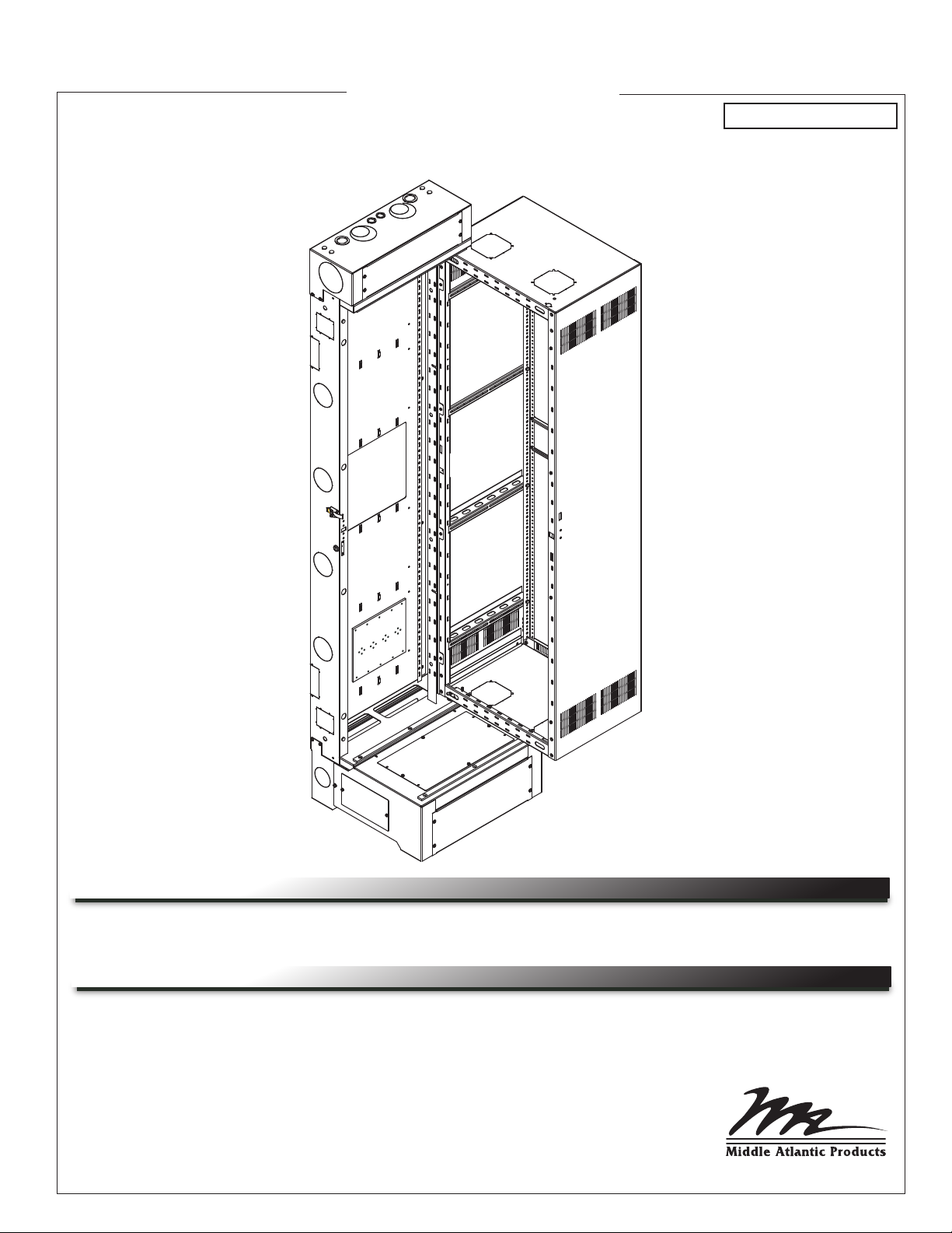
Instruction Sheet
SR SERIES
PIVOTING RACK
U.S. PATENT 7,278,183
THANK YOU
Thank you for purchasing the SR Series Pivoting Rack. Please read these instructions thoroughly
before installing or assembling this product.
PRODUCT FEATURES
• Available in 23.5” and 29” widths.
• The 29” width includes front vertical cable management.
• Tool-Free Quick-Mount™ system for easy mounting of the center section to the backpan on the
job site.
• Pivots 90º on floor base for access to rear connections.
• Zero Clearance Latch option allows side-by-side or corner mounting.
I-00143 Rev P
Page 2

IMPORTANT SAFETY INSTRUCTIONS
• Read these instructions.
• Keep these instructions.
DANGER HAZARDOUS VOLTAGE: The lightning flash with the arrowhead symbol, within an equilateral triangle is intended to alert the user to the
presence of uninsulated dangerous voltage within the product’s enclosure that may be of sufficient magnitude to constitute a risk of electric shock to
persons.
WARNING: A warning alerts you to a situation that could result in serious personal injury or death.
CAUTION: A caution alerts you to a situation that may result in minor personal injury or damage to the product and/or property.
NOTE: A note is used to highlight procedures pertaining to the installation, operation, or maintenance of the product.
WARNING: Failure to read, understand and follow the following information can result in serious personal injury, damage to the
equipment or voiding of the warranty.
CAUTION: To avoid an unstable condition, place heavier components at the bottom of the enclosure. When more than one component
is placed in the enclosure, begin at the bottom of the enclosure and place equipment at the lowest available point, evenly distribute
weight (horizontally) within the enclosure.
Component weight should be distributed as follows:
• 1/2 of the total component weight (at a minimum) placed in the bottom third of the cabinet.
• 1/4 of the total component weight (at a maximum) placed in the middle third of the cabinet.
• 1/4 of the total component weight (at a maximum) placed in the top third of the cabinet.
CAUTION: All installation and assembly steps must be performed by qualified personnel.
• Heed all warnings.
• Follow all instructions.
• Clean only with dry cloth.
• Only use attachments/accessories specified by the manufacturer.
CAUTION: Ensure that the wall has a structural load capacity that will support the weight of the cabinet fully loaded with
equipment.
CAUTION: The following parts are not effectively bonded to the protective earth terminal: Rack rails, lace bars, Lever Lock™, shelves,
baffle, blanking panels, fans, and cable management. If any part needs to be bonded to the protective earth terminal it shall be done in
accordance with Article 250 of the National Electrical Code.
CAUTION: To reduce the risk of personal injury and conform to the UL listing, the system must be grounded and bonded in accor-
dance with Article 250 of the National Electrical Code.
CAUTION: Power cord, for fans or other accessories, need to be secured to ensure that they are routed away from pinch points
and moving parts.
CAUTION: Do not attempt to unload or move the enclosures alone. Make sure to have sufficient amount of personnel and equipment to safely move this product.
CAUTION: Watch hands and fingers around pinch points.
CAUTION: Individual components mounted inside of the wall mount rack must have their own fire enclosure.
SEISMIC COMPLIANCE: An engineered system is vital to achieve seismic rating requirements. A licensed professional engineer must
approve the type of fasteners for the wall where the rack will be mounted. Braced according to speicifications set forth by licensed
architects and engineers, the Middle Atlantic Products rack you purchased is capable of sustaining a phenominal lateral load of high
importance equipment with the frontrails filled to a maximum capacity of 277 lbs. (125.65 kg).
Page 2
Page 3
INSTRUCTIONS IMPORTANTES SUR LA SÉCURITÉ
• Lire ces instructions.
• Conservez ces instructions.
DANGER TENSION DANGEREUSE: Le symbole de la pointe de flèche, dans un triangle équilatéral, est destiné à alerter l'utilisateur sur la
présence de tension dangereuse non isolée dans l'enceinte du produit qui peut être d'une ampleur suffisante pour constituer un risque
d'électrocution.
AVERTISSEMENT: Un avertissement vous avertit d'une situation pouvant entraîner des blessures graves ou la mort.
ATTENTION: Une attention vous avertit d'une situation pouvant entraîner des blessures mineures ou des dommages au produit et/ou à la
REMARQUE: Une remarque est utilisée pour mettre en évidence les procédures relatives à l'installation, au fonctionnement ou à l'entretien du
produit.
AVERTISSEMENT: Ne pas lire, comprendre et suivre les informations suivantes peut entraîner des blessures graves, des
dommages à l'équipement ou de la nullité de la garantie.
ATTENTION: Pour éviter un état instable, placez composants les plus lourds au fond de l'enceinte. Lorsque plus d'un composant est
placé dans la enceinte, commencer par le bas de l'enceinte et placer l'équipement à la point le plus bas disponible, de distribuer
uniformément le poids (horizontalement) dans le enceinte.
Le poids des composants devrait être réparti comme suit:
• 1/2 du poids total de la composante (au minimum) placé dans le tiers inférieur de l'armoire.
• 1/4 du poids total de la composante (au maximum) placé dans le tiers médian de l'armoire.
• 1/4 du poids total de la composante (au maximum) placé dans le tiers supérieur de l'armoire.
ATTENTION: Toutes installation et de montage étapes doivent être effectuées par du personnel qualifié.
• Respectez tous les avertissements.
• Suivez toutes les instructions.
• Nettoyer uniquement avec un chiffon sec.
• N'utilisez que des accessoires spécifiés par le fabricant.
ATTENTION: Veiller à ce que le mur a une capacité de charge structurelle qui supporter le poids de le cabinet entièrement
chargé avec l'équipement.
ATTENTION: Les pièces suivantes ne sont pas correctement liés à la borne de terre de protection: rails de rack, des bars de dentelle,
Lever Lock™, des étagères, des chicanes, des panneaux d'obturation, ventilateurs, et la gestion des câbles. Si une partie doit être lié
à la borne de terre de protection, il doit être fait conformément à l'article 250 du Code national de l'électricité.
ATTENTION: Pour réduire le risque de blessure et se conformer à la liste UL, le système doit être mis à la terre et collé
conformément à l'article 250 du Code national de l'électricité.
ATTENTION: Le cordon d'alimentation, pour les fans ou autres accessoires, doivent être fixé à veiller à ce que ils sont acheminés loin des points de pincement et des pièces mobiles.
ATTENTION: Ne essayez pas de décharger ou déplacer les enceintes seul. Assurez-vous d'avoir quantité suffisante de personnel
et de matériel pour déplacer ce produit en toute sécurité.
ATTENTION: Observez les mains et les doigts autour des points de pincement.
ATTENTION: Les composants individuels montés à l'intérieur de montage mural doivent avoir leur propre armoire à incendie.
CONFORMITÉ SISMIQUE: Un système d'ingénierie est essentiel pour atteindre les exigences d'évaluation sismique. Un ingénieur
professionnel agréé doit approuver le type de fixations pour le mur où le rack sera monté. Conçue selon les spécifications d'architectes
et d'ingénieurs agréés, l'enceinte Middle Atlantic Products que vous avez achetée est capable de supporter une charge latérale
phénoménale d'équipement de grande importance avec les chutes de charge remplies jusqu'à une capacité maximale de 277 lbs.
(125.65 kg).
Page 3
Page 4

WEIGHT RATINGS
Model Weight Rating
All 500 lbs. Maximum Total Rated Load
WARNING: This product is intended for use only with the products and maximum weights indicated. Use with other products or
products heavier than the maximum weights indicated may result in instability causing possible injury. Total equipment weight must
not exceed 500 lbs. (226.8 kg).
AVERTISSEMENT: Cette produit est conçu pour être utilisé uniquement avec les produits et les poids maximum indiqué. unique-
ment avec les produits et les poids maximaux indiqués. En cas d'utilisation avec d'autres produits ou des produits plus lourds que
le poids maximal indiqué, le chariot peut devenir instable et causer des blessures. Le poids total de l'équipement ne doit pas
dépasser 226.8 kg (500 lbs).
SUPPLIED COMPONENTS AND HARDWARE
Support Base
C
Backpan
A
REQUIRED TOOLS
• Power Driver
• 1/2” Socket
• 3/8” Socket
• 5/16” Deep Socket
(2x)
Center Section
B
Key
D
WARNING: Use tools with caution and follow all necessary safety
protocols.
AVERTISSEMENT: Utiliser des outils avec prudence et suivre
tous les protocoles de sécurité nécessaires.
Trim
E
• 3/16” Drill Bit
• Level
• 3’ Step Ladder (Optional)
• No. 2 Phillips Driver
INTRODUCTION
NOTE:
• Enclosures shown in this instruction sheet include show the zero clearance latch (DWRSR-ZL) and
sub plate (SR-SUB) options, which may or may not be a part of your configuration.
• Not all options available for the enclosure are included in these instructions and separate instruction
sheets are available for the individual options.
• Topics in this guide indicate that the zero clearance latch and sub plate options must be installed
prior to the enclosure assembly as do their separate instruction sheets.
Page 4
Page 5
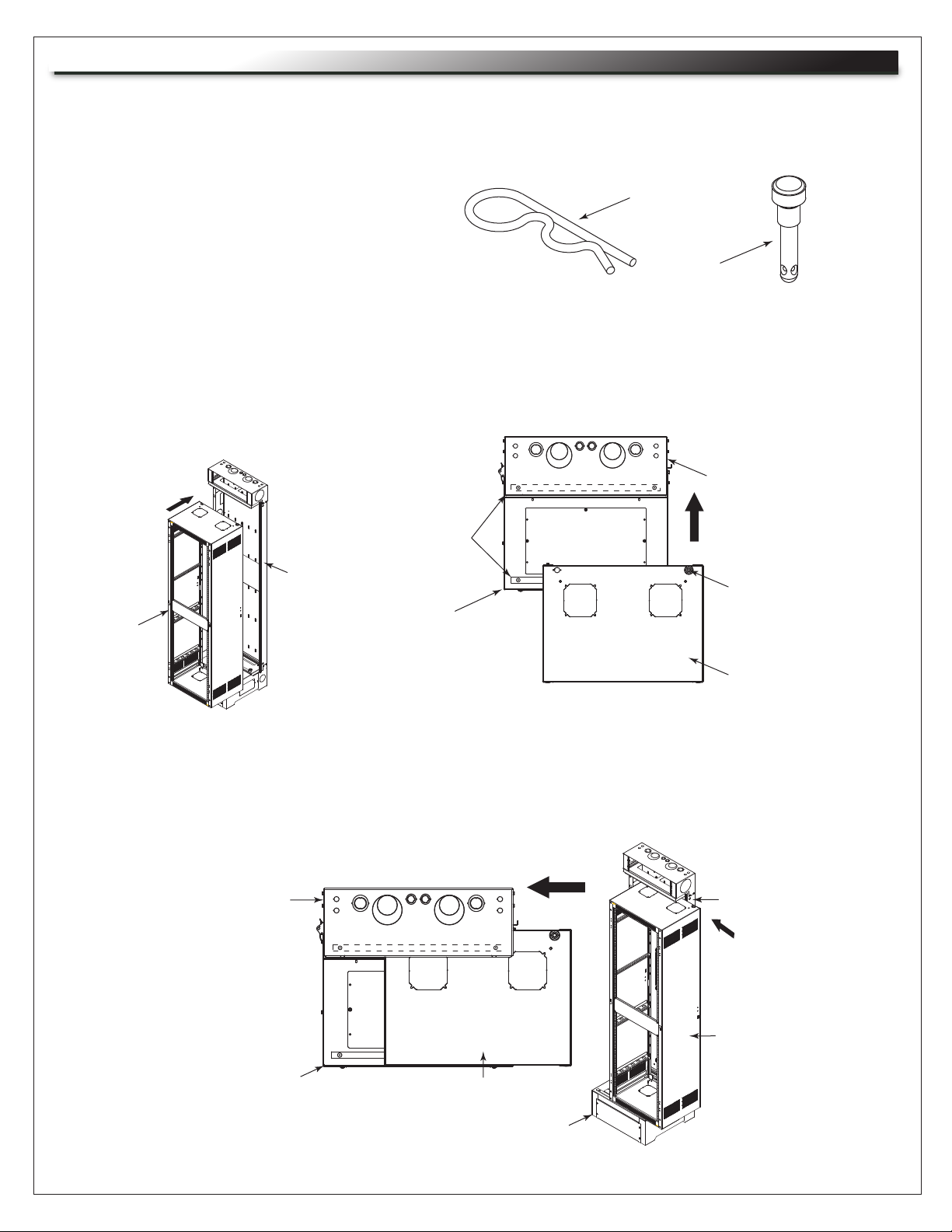
REVERSING THE PIVOT DIRECTION
This rack is factory configured for a right-hand pivot
and may be reversed using the following procedure:
1. If upper wire chamber is already installed, use a
5/16” socket to remove (4x) screws to remove it
from the backpan. (FIGURE A)
2. Use 5/16” socket to remove (4x) screws to remove
the backpan foot from the backpan.
3. Carefully rotate backpan (A) 180º.
4. Replace the upper wire chamber using previously
removed hardware.
5. Replace the backpan foot using previously
removed hardware.
NOTE: Holes are provided on both sides of center section
so bushing can be moved if rack is loaded and backpan
is mounted with pivot on wrong side. Top and bottom may
need to be removed for access to bushings.
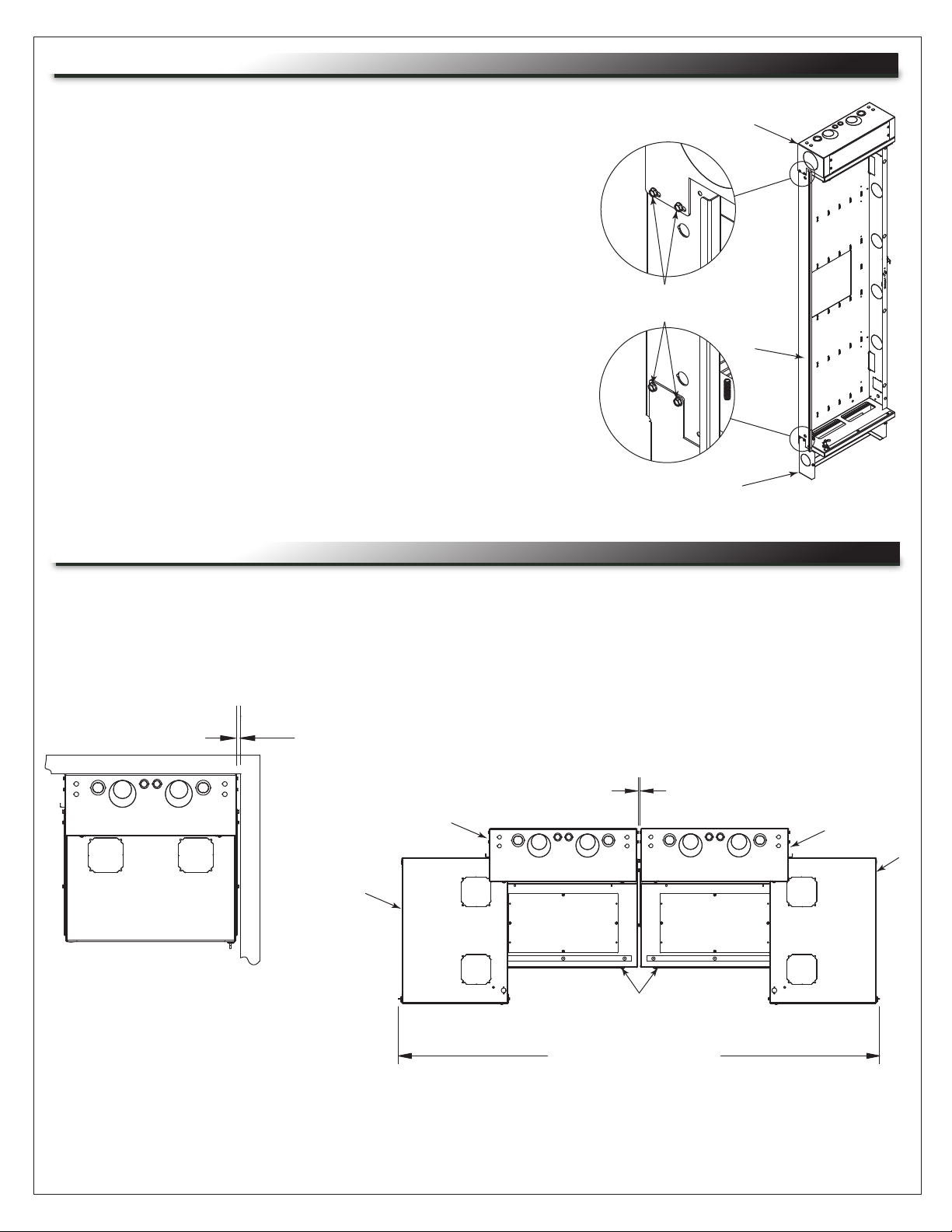
ZERO CLEARANCE LATCH OPTION (DWRSR-ZL)
Upper Wire
Chamber
NOTE: Screws secure wire chamber
and foot on both sides of rack.
A
Backpan
Foot
FIGURE A
NOTE:
• Install the zero clearance latch option before mounting the backpan (A) to the wall and loading
equipment into the rack.
• For installation instructions, refer to the DWRSR-ZL Zero Clearance Latch instruction sheet (I-00142).
• The DWRSR-ZL must be installed for seismic compliance.
.57" min. distance required
between SR and wall or other
SR using Zero Clearance Latch.
.57" minimum distance
A
B
C
74.53" (SR-XX-22)
86.53" (SR-XX-28)
94.53" (SR-XX-32)
A
B
Page 5
Page 6

ZERO CLEARANCE LATCH OPTION (DWRSR-ZL, CONTINUED)
The zero clearance latch option saves
valuable wall space by allowing wall
B
racks to be placed side-by-side, in a
corner, or wherever side clearance is
an issue. This easy to install option
upgrades new SR Series racks to allow
the center section (B) to lock closed
without the need for side latches.
To open, simply pull the convenient
front-mounted handle. (FIGURE B)
Unlike time-consuming threaded rods,
the unique latch provides keylocked
security from the front (keyed
differently from optional front door).
FIGURE B
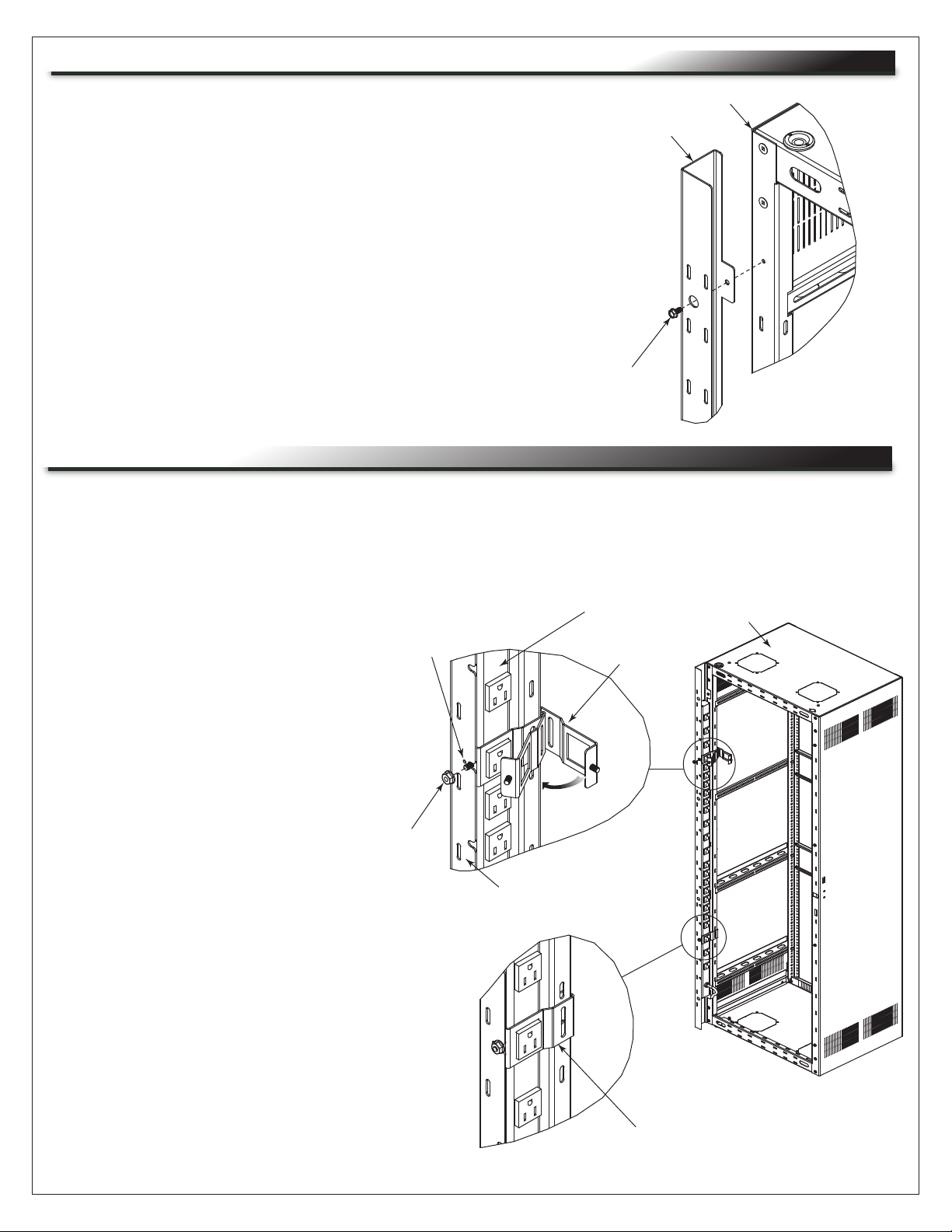
INSTALLING THE SUB PLATE MOUNTING OPTION (SR-SUB)
NOTE: Install the sub plate mounting option before mounting the backpan to the wall and loading
equipment into the rack.
• Insert self-clinching stud through
A
mounting holes in backpan (A),
89-D Bracket
(Not Included)
through SR-SUB, and then tighten
flange nuts on self-clinching studs.
(FIGURE C)
Hardware included with option.
• Each SR-SUB
allows for the
mounting of up
to (4x) 89-D type
brackets, (4x) 1900
boxes or (1x) Raco
3 gang box.
Self-Clinching
Stud
FIGURE C
Flange
Nut
SR-SUB
FIGURE D
(FIGURE D)
Hardware included
with option.
NOTE: Install the sub plate nounting option before mounting the backpan
(A) to the wall and loading equipment into the rack.
FIGURE E
• Mount up to (4x) SR-SUB sub plates to each backpan (depending on
model) using mounting holes and included hardware. (FIGURE E)
NOTE: Shown with center section (B) of enclosure removed for clarity.
Page 6
Page 7

PRIOR TO MOUNTING BACKPAN TO WALL
NOTE:
• When installing next to another SR or wall using the zero clearance latch option, perform the support
base (C) installation for access to the base screws before mounting the backpan (A). For more
information, see “Installing the Base” on page 8.
• On 46 space SR enclosures, you may install either a dust cover or upper wire chamber option on top
of the rack. For more information, refer to the Dust Cover and Upper Wire Chamber Options instruction
sheet (I-00155).
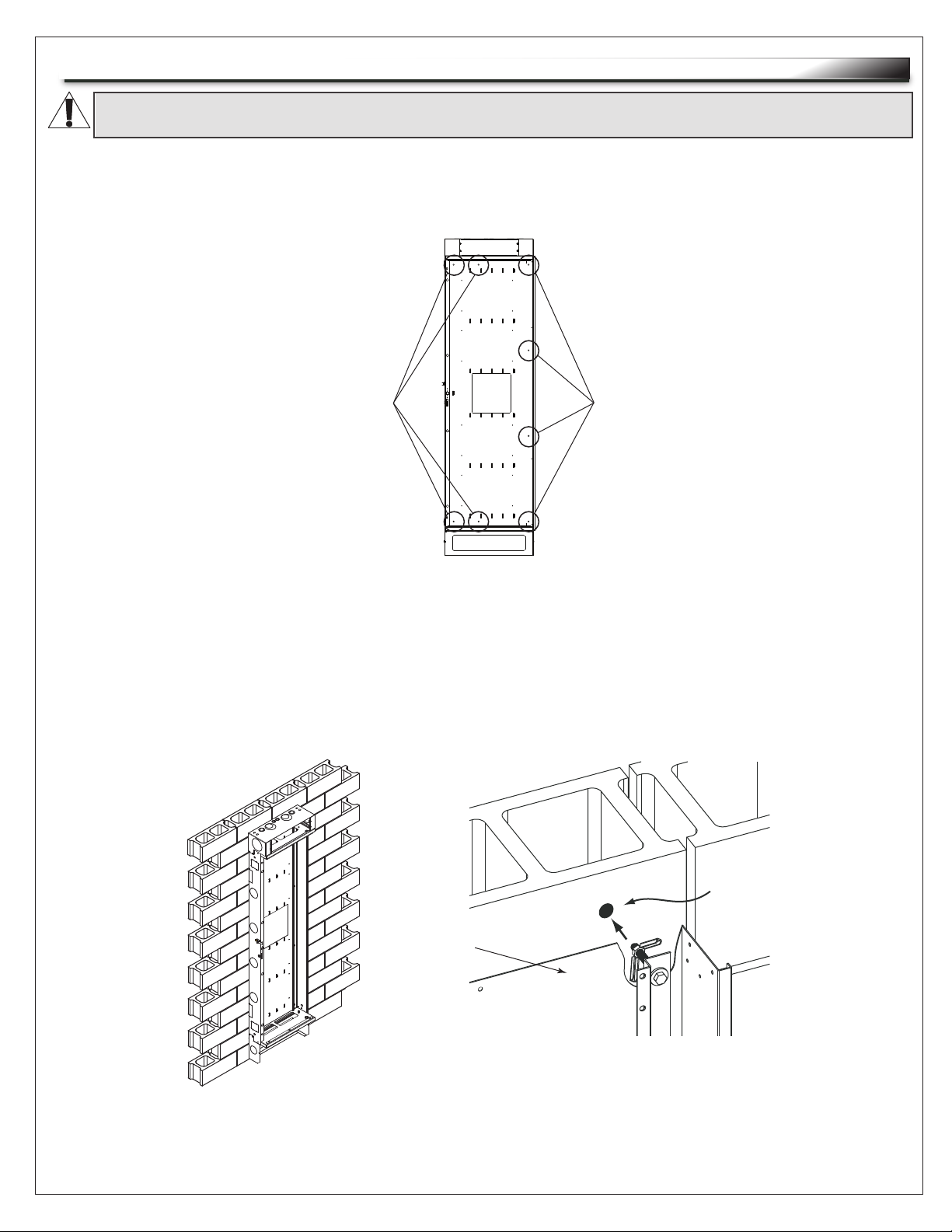
MOUNTING THE BACKPAN TO STUDS
CAUTION: The backpan must be installed plumb and level for proper operation.
ATTENTION: La plaque profilée doit etre aplomb et de niveau pour un fonctionnement.
NOTE:
• Ensure the backpan (A) is screwed to the
Wall Mounting Points
(Latch Side) for 16” Studs
studs. (FIGURE G)
• Use 5/16" diameter lag bolts with a
minimum length of 2" and standard flat
washers for hardware (not provided).
• The standard flat washers must be installed
under the lag bolt heads.
Wall
1. Align backpan (A) to selected wall location
and mark pilot holes through wall
mounting points as shown. (FIGURE F)
Mounting
Points
(Latch Side)
for 24” Studs
Wall Mounting Points
(Pivot Side)
FIGURE F
2. User power driver and 3/16” bit to drill pilot holes on stud center markings. (FIGURE F)
3. Use 1/2” socket, 5/16" lag bolts and washers (not provided) in 6 places: (4x) on pivot side and (2x)
on latch side. (FIGURE F)
1/2” Drywall
A
Stud
Lag bolt must protrude 2"
into the stud.
Drill 3/16"
pilot hole on
stud center.
FIGURE G
Page 7
Page 8
MOUNTING THE BACKPAN TO CONCRETE BLOCK (INSTALL NOT EVALUATED BY UL)
CAUTION: The backpan must be installed plumb and level for proper operation.
ATTENTION: La plaque profilée doit etre aplomb et de niveau pour un fonctionnement.
1. Align backpan (A) to selected wall location and mark pilot holes through wall mounting points as
shown. (FIGURE H)
Wall Mounting Points
(Latch Side)
NOTE: Only 1 column
necessary on latch
side.
Wall Mounting Points
(Pivot Side)
FIGURE H
2. Drill at least 1” into concrete block for your selected hardware (not provided). (FIGURE J)
3. Use toggle bolts and washers (or other appropriate hardware, not provided) in 6 places: (4x) on pivot
side and (2x) on latch side. (FIGURE H)
A
Page 8
1” Hole
in Block
FIGURE J
Page 9

INSTALLING THE BASE
1. Use 3/8” socket to remove (2x) 3/8” screws pre-installed on the bottom foot of the backpan (A).
(FIGURE K)
2. Position the support base (C) to the outside of the
backpan foot (A).
A
3. Use hardware from
previous step to attach
Base mounts to
outside of foot.
the base (C) to the
backpan foot (A).
Pivoting support base
compensates for
variations in floor.
PREPARING TO MOUNT CENTER SECTION
1. Use No. 2 Phillips driver to remove (4x)
screws and remove top access panel
from the upper wire chamber. (FIGURE L)
2. FOR 46 SPACE SR ENCLOSURES
ONLY: Remove dust cover, if installed,
before proceeding. For more
information, refer to the Dust Cover and
Upper Wire Chamber Options instruction
sheet (I-00155).
Access
Panel
FIGURE K
C
Panel removes
for wire access.
Upper
Wire
Chamber
FIGURE L
3. Use 5/16” socket to remove (2x) screws and bottom access panel on the pivot side of the base (C)
only. (FIGURE M)
C
FIGURE M
A
Access
Panel
Page 9
Page 10
MOUNTING THE CENTER SECTION TO THE BACKPAN
NOTE: The pivot pins and security clips needed to mount the center section (B) to the backpan (A) are
pre-installed in the bushings on the backpan top and bottom. (FIGURE N)
1. Remove the clips and unscrew the pins.
Security Clip
FIGURE N
Pivot Pin
2. Remove wire-tied trim inside of center section and set aside for installation.
3. Place center section (B) up on support base (C) with pivot bushing hanging over side of support base
approximately 3” to 6". (FIGURE P)
4. Push center section (B) back. (FIGURE R)
Wear Strip
A
C
B
Top View
A
Pivot
Bushings
B
FIGURE P
FIGURE R
5. Once pivot has passed lower and upper wear strips located on backpan (A), slide center section (B)
over to engage the pivot bushing. (FIGURE S)
Top View
A
A
FIGURE S
B
C
B
C
Page 10
Page 11

MOUNTING THE CENTER SECTION TO THE BACKPAN (CONTINUED)
6. Keeping the center section (B) in the closed position,
insert a pivot pin through the bottom access hole into
bushing, hand tighten fully, and then back out one
turn. (FIGURE T)
Upper
Wire
Chamber
7. Open center section (B) slightly for top pin alignment.
8. Going through the upper wire chamber, drop the
pivot pin into the top bushing (use tip of pin to find
NOTE: Center section
(B) removed for clarity.
alignment) and insert, hand tighten fully, and then back
out one turn.
Bottom
Access
Hole
FIGURE T
Engagement
Area
9. As a final security measure, open the
center section (B) and install security
clips through hole in the pivot pin. (This
prevents removal of the pivot pins from
Handle
the exterior of the enclosure.) (FIGURE U)
FIGURE U
NOTE:
• Slide security clip into engagement area. Do not push pin in all the way. (FIGURE U)
• The center section (B) may be secured to the backpan (A) using the latch.
• The keys (D) may be used for additional security when securing your enclosure in the closed position.
10. Re-install access panels by reversing the steps in “Preparing to Mount Center Section” on page 9.
11. FOR 46 SPACE SR ENCLOSURES ONLY: Install dust cover or upper wire chamber option.
For more information, refer to the Dust Cover and Upper Wire Chamber Options instruction sheet
(I-00155).
Page 11
Page 12
INSTALLING THE TRIM TO THE BACK, PIVOT SIDE OF THE CENTER SECTION
1. Pivot center section (B) into fully open position.
E
B
2. Use power driver and 5/16” deep socket to remove (4x)
pre-installed screws on the back, pivot side of the center
section (B).
3. Use hardware from previous step to attach trim (E) to the
center section’s (B) back, pivot side. (FIGURE W)
NOTE:
• Screws are supplied on both sides for your convenience.
• Leave unused screws in place on opposite side.
Pre-Installed
Thread Cutting
Screw
MOUNTING A POWER STRIP TO THE TRIM
Middle Atlantic Products power strips (PD-815SC, PD-815SC-NS, PD-2415SC,PD-2415SC-NS and
FIGURE W
PD-2420SC-NS only) can be mounted inside the center section trim (E) with the included hardware.
This simplifies cable management with no additional accessories required.
NOTE:
• PD-2415SC, PD-2415SC-NS,
and PD-2420SC-NS power
strips only fit in the 40 and 46
space wall racks and require
the use of 2 clips. Install clips
only to trim notches with a
hole.
• Power strips PD-815SC and
PD-815SC-NS fit in all SR
Series wall racks and require
only 1 clip. Clip can be
installed on any trim notch.
1. Place the power strip in the trim (E),
positioned so the clip mounts over an
outlet and aligns with the notch as
shown. (FIGURE X)
Notch With
Hole
Flange Nut
Power Strip
Clip
E
B
2. Install clip and tighten flange nut as
shown.
NOTE: Installation using a PD-24XX power
strip installed with 2 clips shown.
Page 12
Clip Shown Installed
FIGURE X
Page 13
GROUNDING AND BONDING
Protective Earth Terminals (PET) are located in backpan of the wall rack. These terminals are marked with the symbol
Wall rack parts, center section and door, contain or are provided with bonding points for connection to the backpan / PET.
Protective earth and bonding connections shall be in accordance with Article 250 of the National Electric Code.
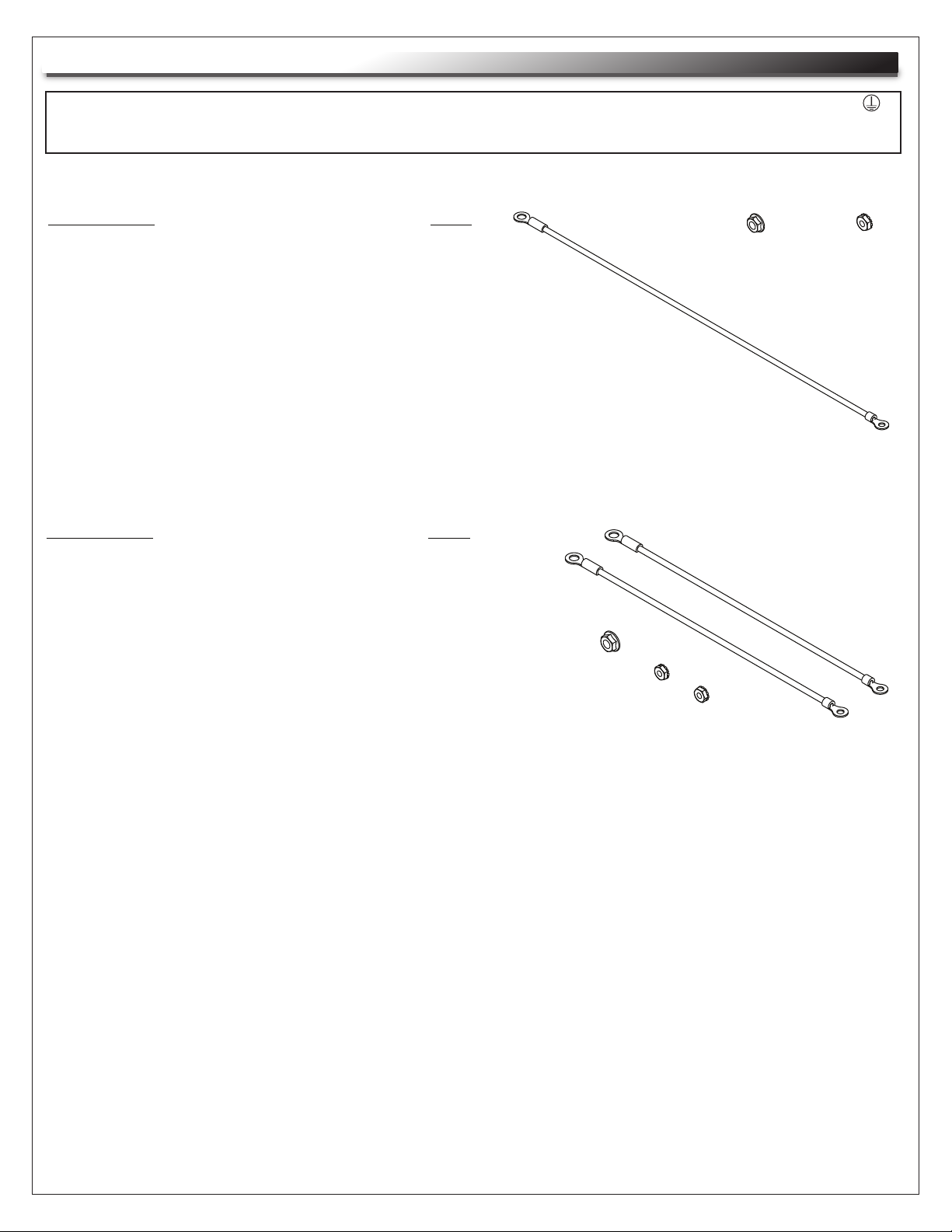
OPTIONAL PROTECTIVE EARTH TERMINAL KIT: #PET-K-D/EWR
PARTS LIST
• Backpan bonding wire [12 Gauge Wire
QTY
(1)
(#10 ring terminal to 1/4” ring terminal) 14”]
• Flange Nut 1/4-20
• Locking Nut 10-32
(1)
(1)
OPTIONAL PROTECTIVE EARTH TERMINAL KIT: #PET-K-SR
PARTS LIST
• Door bonding wire [12 Gauge Wire
QTY
(2)
(#10 ring terminal to 1/4” ring terminal) 9”]
• Flange Nut 1/4-20
• Locking Nut 10-32
(1)
(2)
(1)
(1)
(1)
Page 13
Page 14

GROUNDING AND BONDING (CONTINUED)
1. Attach backpan bonding wire from 1/4”-20 backpan protective earth terminal (PET) to nearest
center section (B) bonding stud (10-32) using hardware provided. (FIGURE Y)
NOTE: The main protective earth ground needs to be the first terminal placed on the PET and this
terminal needs to be secured on its own with a nut. The bonding wire for the center section (B) can
be added to the PET after securing the nut for the main ground.
2. Attach cable entry bonding wire from upper wire chamber to nearest 10-32
center section (B) bonding stud using hardware provided.
3. Attach base bonding wire from support base (C) to nearest
center section (B) bonding stud (10-32) using hardware provided.
B
(2x) 10-32 Upper Wire Chamber
(4x Upper, 4x Lower) 10-32
Center Section Bonding Studs
Upper Wire Chamber
Bonding Studs
(2x) 10-32 Base
Bonding Studs
(2x Upper, 2x Lower)
Backpan PET Studs
A
Top View
C
(2x Upper, 2x Lower)
Backpan PET Studs
FIGURE Y
Page 14
Page 15

WARRANTY
For warranty information, refer to http://www.middleatlantic.com/company/about-us.aspx#warranty
Corporate Headquarters
Corporate Voice: 973-839-1011 - Fax: 973-839-1976 / International Voice: +1 973-839-8821 Fax: +1 973-839-4982
www.middleatlantic.com - info@middleatlantic.com
Middle Atlantic Canada
Voice: 613-836-2501 - Fax: 613-836-2690 / ca.middleatlantic.com customerservicecanada@middleatlantic.ca
Factory Distribution
USA: NJ - CA - IL Canada: ON - BC
At Middle Atlantic Products we are always listening. Your comments are welcome.
Middle Atlantic Products is an ISO 9001 and ISO 14001 Registered Company.
Page 15
Page 16

 Loading...