

Page 1

Instruction Sheet
SR SERIES
PIVOTING RACK
US PATENT 7, 278,183
THANK YOU
Thank you for purchasing the SR Series Pivoting Rack.
Please read these instructions thoroughly before installing and assembling this product.
PRODUCT FEATURES
• Tool-Free Quick-Mount™ system for easy mounting of the center
section to the backpan on the job site.
• Zero Clearance Latch option allows side-by-side or corner mounting.
• Pivots 90º on floor base for access to rear connections.
I-00143 Rev L
Page 2

IMPORTANT SAFETY INSTRUCTIONS / INSTRUCTIONS IMPORTAANTES SUR LA SÉCURITÉ
SAVE ALL INSTRUCTIONS / CONSERVER CES INSTRUCTIONS
DANGER HAZARDOUS VOLTAGE/DANGER HAUTE TENSION
The lightning flash with the arrowhead symbol, within an equilateral
triangle is intended to alert the user to the presence of uninsulated
dangerous voltage within the product’s enclosure that may be of
sufficient magnitude to constitute a risk of electric shock to persons.
L'éclair avec le symbole de flèche dans un triangle équilatéral est
destiné à alerter l'utilisateur de la présence d'une tension dangereuse
non isolée dans l'enceinte du produit qui peut être d'une ampleur
suffisante pour constituer un risque de choc électrique pour les
personnes.
CAUTION/ATTENTION The exclamation point within an equilateral
triangle is intended to alert the user to the presence of important
operating and maintenance (servicing) instructions in the literature
accompanying the appliance.
Le point d'exclamation dans un triangle équilatéral est destiné à
alerter l'utilisateur de la présence d'importants instructions d’opération
et de maintenance (entretien) dans la documentation accompagnant
l'appareil.
WARNING: Failure to read, understand and follow the following information can result in
serious personal injury, damage to the equipment or voiding of the warranty.
AVERTISSEMENT: Ne pas lire, comprendre et suivre les informations
suivantes peut entraîner des blessures graves, des dommages à l'équipement
ou de la nullité de la garantie.
CAUTION: To avoid an unstable condition, place heavier components at the bottom of the
enclosure. When more than one component is placed in the enclosure, begin at the bottom
of the enclosure and place equipment at the lowest available point, evenly distribute weight
(horizontally) within the enclosure.
Component weight should be distributed as follows:
• 1/2 of the total component weight (at a minimum) placed in the bottom third of the cabinet
• 1/4 of the total component weight (at a maximum) placed in the middle third of the cabinet
• 1/4 of the total component weight (at a maximum) placed in the top third of the cabinet
ATTENTION: Pour éviter un état instable, placez composants les plus lourds au
fond de l'enceinte. Lorsque plus d'un composant est placé dans la enceinte,
commencer par le bas de l'enceinte et placer l'équipement à la point le plus bas
disponible, de distribuer uniformément le poids (horizontalement) dans le enceinte.
Le poids des composants devrait être réparti comme suit:
• 1/2 du poids total de la composante (au minimum) placé dans le tiers inférieur de l'armoire
• 1/4 du poids total de la composante (au maximum) placé dans le tiers médian de l'armoire
• 1/4 du poids total de la composante (au maximum) placé dans le tiers supérieur de l'armoire
CAUTION: All installation and assembly steps must be performed by qualified personnel.
ATTENTION: Toutes installation et de montage étapes doivent être effectuées par du
personnel qualifié.
CAUTION: Ensure that the wall has a structural load capacity that will support the weight of
the cabinet fully loaded with equipment.
ATTENTION: Veiller à ce que le mur a une capacité de charge structurelle qui supporter le
poids de le cabinet entièrement chargé avec l'équipement.
Page 2
Page 3

IMPORTANT SAFETY INSTRUCTIONS / INSTRUCTIONS IMPORTAANTES SUR LA SÉCURITÉ
CAUTION: The following parts are not effectively bonded to the protective earth terminal:
Rack rails, lace bars, Lever Lock™, shelves, baffle, blanking panels, and cable management.
If any part needs to be bonded to the protective earth terminal it shall be done in accordance
with Article 250 of the National Electrical Code.
ATTENTION: Les pièces suivantes ne sont pas correctement liés à la borne de terre de
protection: rails de rack, des bars de dentelle, Lever Lock ™, des étagères, des chicanes,
des panneaux d'obturation, et la gestion des câbles. Si une partie doit être lié à la borne de
terre de protection, il doit être fait conformément à l'article 250 du Code national de l'électricité.
CAUTION: Power cord(s), for fans or other accessories, need to be secured to ensure that
they are routed away from pinch points and moving parts.
ATTENTION: Le cordon d'alimentation (s), pour les fans ou autres accessoires, doivent être
fixé à veiller à ce que ils sont acheminés loin des points de pincement et des pièces mobiles.
CAUTION: Do not attempt to unload or move the enclosures alone. Make sure to have
sufficient amount of personnel and equipment to safely move this product.
ATTENTION: Ne essayez pas de décharger ou déplacer les enceintes seul. Assurez-vous
d'avoir quantité suffisante de personnel et de matériel pour déplacer ce produit en toute
sécurité.
CAUTION: To reduce the risk of personal injury, these mounting instructions must be followed
and proper weight capacities must be observed.
ATTENTION: Pour réduire le risque de blessures, ces instructions de montage doivent être
respectées et les capacités de poids appropriées doivent être respectées.
SEISMIC COMPLIANCE: An engineered system is vital to achieve seismic rating
requirements. A licensed professional engineer must approve the type of fasteners for the
wall where the rack will be mounted. Braced according to speicifications set forth by licensed
architects and engineers, the Middle Atlantic Products rack/enclosure you purchased is
capable of sustaining a phenominal lateral load of high importance equipment with the front
rails filled to a maximum capacity of 277 lbs.
WEIGHT RATINGS
Model Weight Rating
All 500 lbs.
Page 3
Page 4

REQUIRED TOOLS
• 5/16" socket / nut driver
• 3/8" socket / nut driver
• 3' step ladder (optional)
• Level
• Drill
Zero Clearance Latch
Front mounted Zero Clearance Latch saves
valuable wall space by allowing wall racks to
be placed side-by-side, in a corner, or wherever
side clearance is an issue. This easy to install
option upgrades new SR Series racks to allow
the center section to lock closed without the
need for side latches - to open, simply pull the
convenient front-mounted handle. Unlike
time-consuming threaded rods, the unique
latch provides keylocked security from the
front (keyed differently from optional front
door). Part # DWRSR-ZL
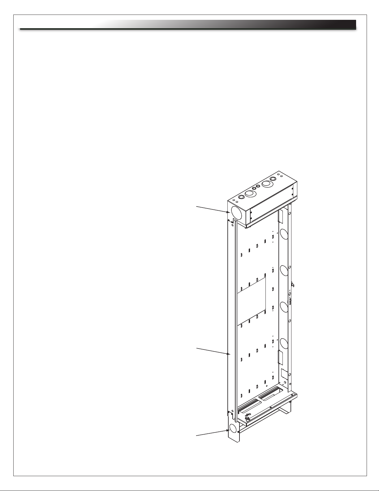
Backpan
(Page 5)
Optional SR-SUB
sub-plate mounting
kits available
(Page 11)
Removable
access panel
Upper Wire
Chamber
Pivoting equipment
rack (Page 7)
NOTE:
• It is recommended that this option is installed
before the rack is loaded.
• The DWRSR-ZL MUST be installed for
the rack to be seismic compliant.
Support base
(Page 6)
Page 4
Page 5

WOOD STUD WALL INSTALLATION
NOTE:
• When assembling the SR-46-28, refer to instruction sheet # I-00155, supplied with the upper wire
chamber to be attached after completing this assembly.
• When installing next to another SR or a wall using the DWRSR-ZL zero clearance latch, perform
step 3 prior to step 1 for access to base screws.
• For proper operation this unit must be installed plumb and level.
1. Rack ships with hinge on right. To reverse pivot, refer to page 10. To mount SR-SUB sub plate,
refer to page 11 before moving to step 2.
2. Mount backpan to wall.
STUD WALL INSTALLATION
Lag bolt must protrude 2" into the 2 X 4
Use 5/16" lag bolt
and washer
(customer supplied)
6 places: 4 in hinge side and
2 in latch side
BLOCK WALL INSTALLATION (INSTALLATION NOT EVALUATED BY UL)
Drill 3/16"
pilot hole on
stud center
Use toggle bolt
and washer
(customer supplied)
in 6 places: 4 in hinge
side and 2 in latch side
Page 5
1” Hole
in hollow
Page 6

INSTALLATION (CONTINUED)
3. Support base attachment: position the support base to the outside of the Backpan foot and attach with
preinstalled hardware located in the bottom foot of Backpan.
Mounts to
outside of foot
Pivoting support base
compensates for
variations in floor
Panel removes
for wire access
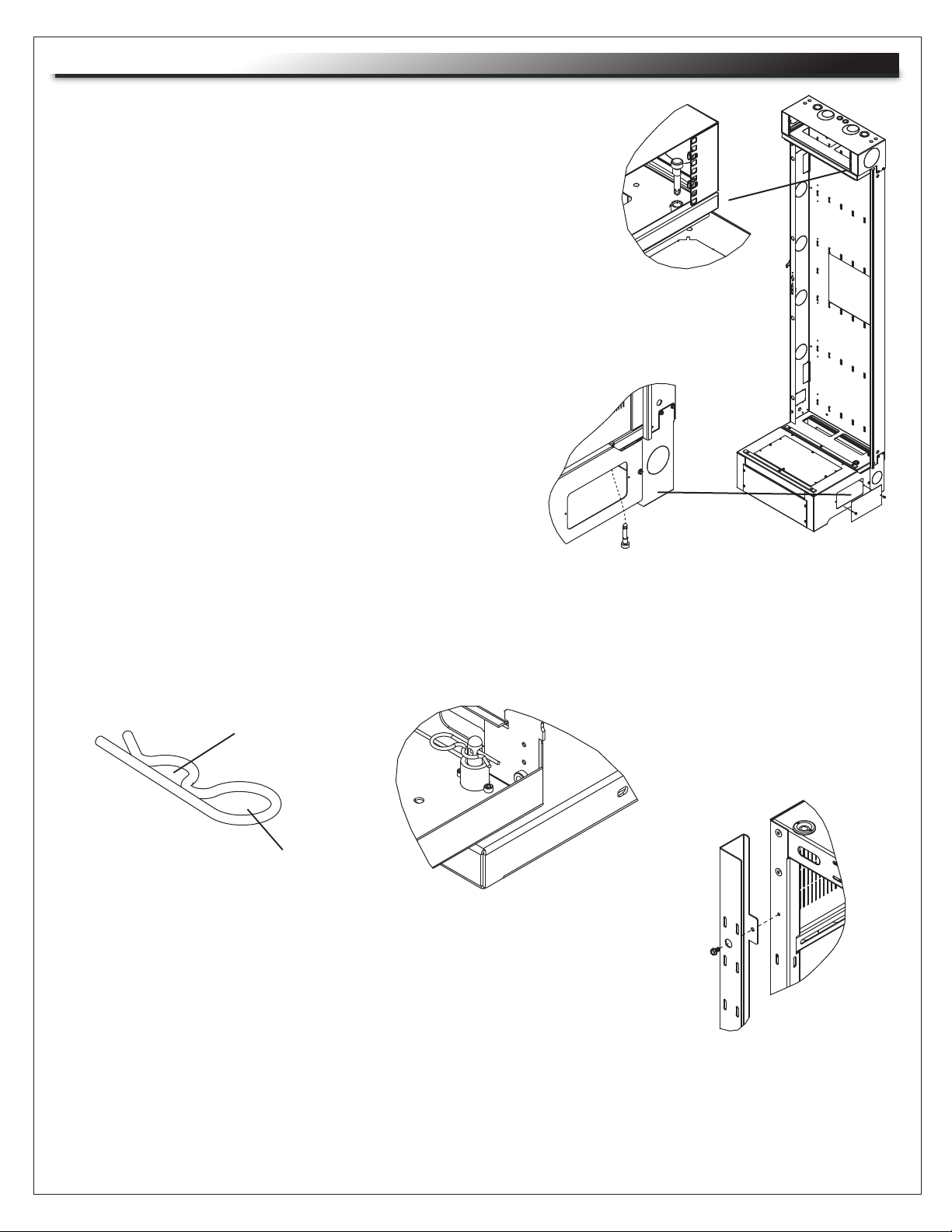
4a. Remove top access panel.
ACCESS
PANEL
4b. Remove bottom access panel on the pivot side of the riser base only.
Page 6
ACCESS
PANEL
Page 7

INSTALLATION (CONTINUED)
5. The pivot pins and security clips needed to mount the Center Section to the Backpan are preinstalled
in the bushings on the Backpan top and bottom. Please remove the clips and unscrew the pins.
SECURITY CLIP PIVOT PIN
NOTE: Remove trim which is wire-tied inside center section. (set aside for later installation)
6. Place Center Section up on support base with pivot bushing hanging over side of support base by
3" to 6".
7a. Push center section back.
WEAR STRIP
PIVOT
BUSHINGS
7b. Once pivot has passed lower and upper wear strips located on back pan, slide center section over
to engage the pivot bushing.
Page 7
Page 8
INSTALLATION (CONTINUED)
8. Keeping the center section in the closed position insert a pivot
pin through the bottom access hole into bushing and hand tighten
fully, then back out one turn.
OPEN CENTER SECTION
SLIGHTLY FOR TOP PIN
ALIGNMENT
9. Going through the upper wire chamber drop the
pivot pin into the top bushing (use tip of pin to find
alignment) and insert, hand tighten fully, then back
out one turn.
SHOWN WITH CENTER
SECTION REMOVED FOR
CLARITY
10. As a final security measure open the center section and install security clips through hole.
(Prevents removal of the pivot pins from the exterior of the enclosure)
NOTE: Slide security clip into engagement area. Do not push pin all the way in.
ENGAGEMENT
AREA
HANDLE
11. Install trim on the pivot side with 5/16" socket / nut driver using screws
preinstalled on the back of the center section.
NOTE: Self tapping screws supplied on both sides for your convenience.
Leave unused self-tapping screws in place on opposite side.
12. Reinstall access panels.
13. SR-46-28 ONLY: refer to instruction sheet I-00155 included with the
upper wire chamber and dust cover to complete assembly.
Page 8
Page 9

MOUNT POWER STRIP
Middle Atlantic Products power strips (PD-815SC, PD-815SC-NS, PD-2415SC,PD-2415SC-NS and
PD-2420SC-NS only) can be mounted inside the center section trim with the included hardware. Simplifies
cable management with no additional accessories required.
NOTE:
• PD-2415SC, PD-2415SC-NS,
and PD-2420SC-NS power strips
only fit in the 40 and 46 space wall
racks and require the use of 2 clips.
NOTCH WITH
HOLE
POWER STRIP
CLIP
Install clips only to trim notches with
a hole.
• Power strips PD-815SC and
PD-815SC-NS fit in all SR Series wall
racks and require only 1 clip. Clip can
be installed on any trim notch.
FLANGE NUT
1. Place the power strip in the trim,
positioned so the clip mounts over an
TRIM
outlet and clip aligns with the notch as
shown.
2. Install clip and tighten flange nut as
shown.
NOTE: Installation using a PD-24XX power
strip installed with 2 clips is shown.
CLIP SHOWN INSTALLED
DECORA® STYLE LASER KNOCKOUT
The face of the top and bottom of the SR wall rack has a knockout for the mounting of the RPS
Series remote power switch from Middle Atlantic Products or any low voltage Decora
®
device.
(visit middleatlantic.com for more details)
DECORA® STYLE LKO
Page 9
Page 10
CHANGING PIVOT DIRECTION (PRIOR TO INSTALLATION)
This rack is factory set up for right hand pivot. To change this product to left hand pivot.
1. Remove the Wire Chamber. (top)
2. Remove the Backpan Foot. (bottom)
3. Rotate Backpan 180º to provide pivot to the left side.
4. Replace the Wire Chamber (top) using previously removed hardware.
5. Replace the Backpan Feet (bottom) using previously removed hardware.
The above procedure has now provided you with a left hand pivoting rack.
Follow the previous pages of instructions to complete the assembly.
WIRE CHAMBER
NOTE: Holes are supplied on both sides of center
section so bushing can be moved if rack is loaded
and backpan is mounted with pivot on wrong side.
Top and bottom may need to be removed for access
to bushings.
BACKPAN
FOOT
Page 10
Page 11

SR-SUB SUB PLATE MOUNTING KIT
NOTE:
The SR-SUB must be installed prior
to mounting the Backpan to the wall
Insert self clinching stud through
mounting holes in backpan of SR
Series pivoting rack and through
SR-SUB, then tighten flange nuts
on self clinching studs. Hardware
included.
SELF-CLINCHING
STUD
89-D BRACKET
(NOT INCLUDED)
SR-SUB
FLANGE
NUT
Each SR-SUB allows for the
mounting of up to (4) 89-D type
brackets, (4) 1900 boxes or
(1) Raco 3 gang box. Hardware
included.
Mount up to 4
SR-SUB sub plates
(depending on model)
to each SR Series
Backpan using
mounting holes and
included hardware.
(Shown with main
body of enclosure
removed from
Backpan for clarity)
DWRSR-ZL ZERO CLEARANCE LATCH
NOTE: When utilizing the DWRSR-ZL Latch for side-by-side mounting, mounting in a corner, or wherever
clearance is an issue, it is important to install the latch before mounting equipment. Refer to instruction
sheet I-00142 (included with DWRSR-ZL) for installation instructions.
.57" min. distance required
between SR and wall or other
SR using Zero Clearance Latch.
.57" minimum distance
74.53" (SR-XX-22)
86.53" (SR-XX-28)
94.53" (SR-XX-32)
Page 11
Page 12

GROUNDING AND BONDING
Protective Earth Terminals (PET) are located in backpan of the wall rack. These terminals are marked with the symbol
Wall rack parts, center section and door, contain or are provided with bonding points for connection to the backpan / PET.
Protective earth and bonding connections shall be in accordance with Article 250 of the National Electric Code.
OPTIONAL PROTECTIVE EARTH TERMINAL KIT: #PET-K-D/EWR
PARTS LIST
• Backpan bonding wire [12 Gauge Wire
QTY
(1)
(#10 ring terminal to 1/4” ring terminal) 14”]
• Flange Nut 1/4-20
• Locking Nut 10-32
(1)
(1)
OPTIONAL PROTECTIVE EARTH TERMINAL KIT: #PET-K-SR
PARTS LIST
• Door bonding wire [12 Gauge Wire
QTY
(2)
(#10 ring terminal to 1/4” ring terminal) 9”]
• Flange Nut 1/4-20
• Locking Nut 10-32
(1)
(2)
(1)
(1)
(1)
Page 12
Page 13

GROUNDING AND BONDING (CONTINUED)
1. Attach backpan bonding wire from 1/4”-20 backpan protective earth terminal (PET) to nearest
center section bonding stud (10-32) using hardware provided.
NOTE: The main protective earth ground needs to be the first terminal placed on the PET and this
terminal needs to be secured on its own with a nut. The bonding wire for the center section can
be added to the PET after securing the nut for the main ground.
Backpan PET Studs
2. Attach cable entry bonding wire from cable entry box to nearest 10-32
(2 Upper / 2 Lower)
center section bonding stud using hardware provided.
3. Attach base bonding wire from base to nearest center section
bonding stud (10-32) using hardware provided.
Center Section
Center Section Bonding Studs
10-32 (4 Upper/ 4 Lower)
TOP VIEW
Base Box
Cable Entry Box
Cable Entry Bonding
Studs 10-32 (2)
Base Bonding
Studs 10-32 (2)
Page 13
Backpan PET Studs
(2 Upper / 2 Lower)
Page 14

WARRANTY
Middle Atlantic Products (the "Company") warrants the product to be free from defects in material or workmanship under normal use and
conditions for the lifetime of the product.
The Company's entire liability to the purchaser, and the purchaser's (or any other party's) sole and exclusive remedy, under this warranty
shall be limited, at the Company's option, to either (a) return of and refund of the price paid for, or (b) repair or replacement at the
Company's factory of the products purchased, or any part or parts thereof, which the Company has determined to be defective after
inspection thereof at the Company's factory.
This warranty does not cover damage due to acts of God, accident, misuse, abuse or negligence by parties other than the Company, or
any modification or alteration of the products. In addition, this warranty does not cover damage due to improper handling, assembly,
installation or maintenance.
THIS WARRANTY IS IN LIEU OF ALL OTHER WARRANTIES OF ANY KIND, EITHER EXPRESSED OR IMPLIED, INCLUDING, BUT
NOT LIMITED TO, IMPLIED WARRANTIES OF MERCHANTABILITY AND FITNESS FOR A PARTICULAR PURPOSE.
TO THE MAXIMUM EXTENT PERMITTED BY APPLICABLE LAW, IN NO EVENT SHALL THE COMPANY BE LIABLE FOR ANY
SPECIAL, INCIDENTAL, INDIRECT, OR CONSEQUENTIAL DAMAGES WHATSOEVER (INCLUDING, WITHOUT LIMITATION,
DAMAGES FOR LOSS OF BUSINESS PROFITS, BUSINESS INTERRUPTION OR ANY OTHER PECUNIARY LOSS) ARISING OUT OF
THE USE OF THE PRODUCTS PURCHASED, EVEN IF THE COMPANY HAS BEEN ADVISED OF THE POSSIBILITY OF SUCH
DAMAGES. THE COMPANY'S LIABILITY TO THE PURCHASER (OR ANY OTHER PARTY) HEREUNDER, IF ANY, SHALL IN NO
EVENT EXCEED THE PURCHASE PRICE OF THE PRODUCTS PAID TO THE COMPANY.
Corporate Headquarters
Corporate Voice 973-839-1011 - Fax 973-839-1976 / International Voice +1 973-839-8821 - Fax +1 973-839-4982
middleatlantic.com - info@middleatlantic.com
Middle Atlantic Canada
Voice 613-836-2501 - Fax 613-836-2690 / middleatlantic.ca - customerservicecanada@middleatlantic.ca
Factory Distribution
USA: NJ - CA - IL Canada: ON - BC
At Middle Atlantic Products we are always listening. Your comments are welcome.
Middle Atlantic Products is an ISO 9001 and ISO 14001 Registered Company.
Page 14
 Loading...