

Page 1
User Manual
Select Series PDU with RackLink®
Monitor | Control | Alert | Report | Analyze
THANK YOU
Thank you for purchasing a Select Series PDU with RackLink® product. Please read these
instructions thoroughly before installing this product.
I-00768 Rev B
Page 2

TABLE OF CONTENTS
IMPORTANT SAFETY INSTRUCTIONS .............................................................................................. 5
REGULATORY COMPLIANCE ......................................................................................................... 7
Federal Communications Commission (FCC) Compliance Statement .......................................... 7
Industry Canada (IC)...................................................................................................................... 7
INSTRUCTIONS IMPORTANTES SUR LA SÉCURITÉ ....................................................................... 8
CONFORMITÉ RÉGLEMENTAIRE ................................................................................................. 10
Déclaration de conformité de la Federal Communications Commission (FCC) ........................... 10
Industrie Canada (IC)................................................................................................................... 10
INTRODUCTION ................................................................................................................................ 11
Key Features ................................................................................................................................... 11
SYSTEM REQUIREMENTS ............................................................................................................... 12
INSTALLING THE DEVICE DISCOVERY SO F TWARE AND ACCESSING A CONNECTED
RACKLINK’S BROWSER-BASED INTERFACE ................................................................................. 13
Installing the RackLink Device Discovery software on a PC:........................................................... 13
Installing the RackLink Device Discovery software on a MAC: ........................................................ 15
Using Device Discovery................................................................................................................... 18
SETTING UP YOUR RACKLINK DEVICE FOR THE FIRST TIME .................................................... 20
Configuring TCP/IP on Your PC ...................................................................................................... 20
Configuring TCP/IP in RackLink via Browser-Based Interface ........................................................ 24
Configuring TCP/IP via Device Discovery ....................................................................................... 25
DOWNLOADING AND USING THE MOBILE APP ............................................................................. 29
USING THE BROWSER-BASED INTERFACE .................................................................................. 30
Logging in to the Browser-Based Interface...................................................................................... 30
Understanding System Confirmations ............................................................................................. 32
Viewing Help Information................................................................................................................. 34
Viewing and Configuring Information on the Dashboard ................................................................. 34
Initiating a Sequence ................................................................................................................... 34
Configuring Outlet Controls .......................................................................................................... 35
Page ii
Page 3

TABLE OF CONTENTS
Viewing Status Log Information ................................................................................................... 40
Configuring Administrator Settings .................................................................................................. 42
Logging in to the Administrator Settings Menu ............................................................................ 42
Configuring Date/T ime Settings ................................................................................................... 43
Configuring Device Settings ......................................................................................................... 45
Configuring Email Settings ........................................................................................................... 47
Restoring Factory Defaults .......................................................................................................... 49
Updating Device Firmware ........................................................................................................... 51
Configuring Network Settings ...................................................................................................... 53
Passwords ................................................................................................................................... 55
UNDERSTANDING AN AUTOPING CO NFIGURATION .................................................................... 57
Connecting Your Equipment ............................................................................................................ 57
Measuring Modem/Router Start-Up Time ........................................................................................ 58
Calculating Frequency, Failures, and Cycles .................................................................................. 58
Configuring AutoPing in Your RackLink .......................................................................................... 59
FREQUENTLY ASKED QUESTIONS ................................................................................................. 62
General Questions .......................................................................................................................... 62
Connectivity Questions .................................................................................................................... 62
Control System Questions ............................................................................................................... 63
Outlet LED States ............................................................................................................................ 63
RACKLINK SELECT MODEL DIAGRAMS ......................................................................................... 64
RLNK-215 Diagrams ....................................................................................................................... 64
RLNK-215 Front View .................................................................................................................. 64
RLNK-215 Rear View................................................................................................................... 65
RLNK-415R Diagrams ..................................................................................................................... 65
RLNK-415R Front View ............................................................................................................... 66
RLNK-415R Rear View ................................................................................................................ 66
RLNK-915R Diagrams ..................................................................................................................... 67
RLNK-915R Front View ............................................................................................................... 67
RLNK-915R Rear View ................................................................................................................ 67
Page iii
Page 4

TABLE OF CONTENTS
RLNK-1015V Diagrams ................................................................................................................... 68
RLNK-1015V Bottom View ........................................................................................................... 68
RLNK-1015V Front View .............................................................................................................. 68
RLNK-1615V Diagrams ................................................................................................................... 69
RLNK-1615V Bottom View ........................................................................................................... 69
RLNK-1615V Front View .............................................................................................................. 70
WARRANTY ....................................................................................................................................... 71
Page iv
Page 5
DANGER HAZARDOUS VOLTAGE: The lightning flash with the arrowhead symbol, within an equilateral triangle is
WARNING: A warning alerts you to a situation that could result in serious personal injury or death.
CAUTION: A caution alerts you to a situation that may result in minor personal injury or damage to the product and/or
WARNING: Failure to read, understand and follow the following information can result in serious personal injury, damage
WARNING: The apparatus shall not be exposed to dripping or splashing and that no objec ts filled with liquids, such as
CAUTION: The socket-outlet shall be installed near the equipment and shall be easily accessible.
CAUTION: Use indoor in dry locations only.
IMPORTANT SAFETY INSTRUCTIONS
• Read these instructions.
• Keep these instructions.
intended to alert the user to the presence of uninsulated dangerous voltage within the product’s enclosure that may be of
sufficient magnitude to constitute a risk of electric shock to persons.
property.
NOTE: A note is used to highlight procedures pertaining to the installation, operation, or maintenance of the product.
DANGER HAZARDOUS VOLTAGE: To reduce the risk of electrical shock: Always unplug this device from the electrical
outlet before cleaning.
to the equipment or voiding of the warranty. It is the responsibility of the Installer/User to ensure that this product is loaded
according to specifications .
WARNING: Risk of Electric Shock: Connect the device to a properly grounded outlet only. Do not defeat the safety
purpose of the polarized or grounding-type plug. A polarized plug has two blades with one wider than the other. A
grounding type plug has two blades and a third grounding prong. The wide blade or the third prong is provided for your
safety. If the provided plug does not fit into your outlet, consult an electrician for replacement of the obsolete outlet.
• Heed all warnings.
• Follow all instructions.
• Clean only with dry cloth.
• Only use attachments/accessories specified by the
manufacturer.
vases, shall be placed on the apparatus.
WARNING: To reduce the risk of burns, fire, electric shock, or injury to persons:
• Unplug from outlet before putting on or taking off parts.
• Close supervision is necessary when this device is used by, or near children, invalids, or disabled persons.
• Use this device only for its intended use as described in these instructions. Do not use attachments not
recommended by the manufacturer.
• Never operate the device if it has a damaged cord or plug, if it is not working properly, if it has been dropped or
damaged, or dropped into water. Return the device to a service center for examination and repair.
• Protect the power cord from being walked on or pinched particularly at plugs, convenience receptacles, and the point
where they exit from the apparatus.
• Keep the cord away from heated surfaces.
• Never drop or insert any object into any opening.
• Do not use outdoors.
• Do not operate where aerosol (spray) products are being used or where oxygen is being administered.
• To disconnect, turn all controls to the off position, then remove plug from outlet.
Page 5
Page 6

IMPORTANT SAFETY INSTRUCTIONS
Safety Instructions: Rack Mount
Elevated Operating Ambient: If installed in a closed or multi-unit rack assembly, the operating ambient temperature of
the rack environment may be greater than room ambient. Therefore, consideration should be given to installing the
equipment in an environment compatible with the maximum ambient temperature (Tma) specified by the manufacturer.
Reduced Air Flow: Installation of the equipment in a rack should be such that the amount of air flow required for safe
operation of the equipment is not compromised.
Mechanical Loading: Mounting of the equipment in the rack should be such that a hazardous condition is not achieved
due to uneven mechanical loading.
Circuit Overloading: Consideration should be given to the connection of the equipment to the supply circuit and the
effect that overloading of the circuit might have on overcurrent protection and supply wiring. Appropriate consideration of
equipment nameplate ratings should be used when addressing this concern.
Reliable Earthing: Reliable earthing of rack-mounting equipment should be maintained. Particular attention should be
given to supply connections other than direct connections to the branch circuit (e.g. use of power strips).
Disconnect Device (Pluggable Equipment): The socket-outlet shall be installed near the equipment and shall be easily
accessible.
When using electrical products, basic precautions should always be followed, including the following:
• Read and follow all instructions before using.
• There are no user-serviceable components within this device. Removal of the cover from this device may present
a shock hazard, and void the warranty.
• The mains plug is used as your disconnect device. This device shall remain readily operable.
• Unplug this apparatus during lightning storms or when unused for long periods of time.
• Do not overload the wall outlet where this device is bei ng connec ted . Do not over l oad this dev ice. Ens ur e the total
load to this device does not exceed that which is listed in the specifications section of this manual.
• Ensure this device is connected to a properly grounded AC power source. Ensure the device is plugged into a
source providing the required 120V. Do not use a plug adapter that defeats the ground pin of the AC plug.
Page 6
Page 7

IMPORTANT SAFETY INSTRUCTIONS
REGULATORY COMPLIANCE
Federal Communications Com mi s sion ( FCC) Compliance Statement
CAUTION: Any changes or modifications not expressly approved by the party responsible for compliance could void the
user's authority to operate the equipment.
NOTE: This equipment has been tested and found to comply with the limits for a Class B digital device, pursuant to part 15 of the FCC
Rules. These limits are designed to provide reasonable protection against harmful interference in a residential installation. This
equipment generates, uses and can radiate radio frequency energy and, if not installed and used in accordance with the instructions,
may cause harmful interference to radio communications. However, there is no guarantee that interference will not occur in a particular
installation. If this equipment does cause harmful interference to radio or television reception, which can be determined by turning the
equipment off and on, the user is encouraged to try to correct the interference by one or more of the following measures:
• Reorient or relocate the receiving antenna.
• Increase the separation between the equipment and receiver.
• Connect the equipment into an outlet on a circuit different from that to which the receiver is connected.
• Consult the dealer or an experienced radio/TV technician for help.
Industry Canada (IC)
ICES-003 Class B Notice. This Class B digital apparatus complies with Canadian ICES-003.
Page 7
Page 8
DANGER TENSION DANGEREUSE: Le symbole de la pointe de flèche, dans un triangle équilatéral, est destiné à alerter
AVERTISSEMENT: Un avertissement vous avertit d'une situation pouvant entraîner des blessures graves ou la mort.
ATTENTION: Une attention vous avertit d'une situation pouvant entraîner des blessures mineures ou des dommages au
AVERTISSEMENT: Ne pas lire, comprendre et suivre les informations suivantes peut entraîner des blessures graves, des
AVERTISSEMENT: Risque de choc électrique: Brancher le meuble uni quement à une prise correctement mise à la terre.
AVERTISSEMENT: L'appareil ne doit pas être exposé à des éclaboussures et aucun objet rempli de liquide, comme des
AVERTISSEMENT: Pour réduire les risques de brûlures, d'incendie, de choc électrique ou de blessures:
ATTENTION: La prise de courant doit être installée près de l'équipement et doit être facilement accessible.
ATTENTION: Pour être utilisé en intérieur dans un endroit sec seulement.
INSTRUCTIONS IMPORTANTES SUR LA SÉCURITÉ
• Lire ces instructions.
• Conservez ces
instructions.
l'utilisateur sur la présence de tension dangereuse non isolée dans l'enc einte du produit qui peut être d'une ampleur
suffisante pour constituer un risque d'électrocution.
produit et/ou à la propriété.
REMARQUE: Une remarque est utilisée pour mettre en évidence les procédures relatives à l'installation, au fonctionnement
ou à l'entretien du produit.
DANGER TENSION DANGEREUSE: Pour réduire le risque de choc électrique: Toujours débrancher le meuble de la
prise électrique avant de le nettoyer.
dommages à l'équipement ou de la nullité de la garantie. Il incombe à l'installateur/utilisateur de s'assurer que ce produit
est chargé conformément aux spécifications.
• Respectez tous les
avertissements.
• Suivez toutes les instructions.
• Nettoyer uniquement avec un chiffon sec.
• N'utilisez que des accessoires spécifiés par le fabricant.
Ne pas détériorer le dispositif de sécurité de la fiche polarisée ou de la fiche de terre. Une fiche polarisée possède deux
broches, dont l'une plus l arge que l'autre. Une fiche de type terre possède deux broches et une troisième de mise à la
terre. La broche large ou la troisième fiche sont fournies pour des raisons de sécurité. Si la fiche fournie n'entre pas dans
votre prise de courant, veuillez faire appel à un électricien pour remplacer la prise obsolète.
vases, ne doit être placé sur l'appareil.
• Débrancher de la prise électrique avant d'installer ou de retirer des pièces.
• Surveiller étroitement ce meuble s'il est utilisé par ou à proximité d'un enfant, d'une personne invalide ou handicapée.
• N'utiliser ce meuble que pour l'usage auquel il est destiné, tel que décrit dans la présente fiche d'instructions. Ne pas
utiliser d'accessoires non recommandés par le fabricant.
• Ne jamais utiliser ce meuble si le cordon ou la prise est endommagé, s'il ne fonctionne pas correctement, s'il est
tombé ou est endommagé, ou s'il est tombé dans l'eau. Renvoyer le meuble à un centre de service après-vente pour
qu'il soit examiné et réparé.
• Le cordon d'alimentation doit être placé de manière à éviter qu'il soit piétiné ou pincé, notamment au niveau des
prises, des réceptacles et à la sortie de l'appareil.
• Garder le cordon d'alimentation loin des surfaces chauffées.
• Ne jamais faire tomber ou introduire un objet dans une ouverture.
• Ne pas utiliser en extérieur.
• Ne pas utiliser dans des lieux où des produits aérosols sont utilisés ou à proximité d'une source d'oxygène.
• Pour débrancher, placer tous les boutons en position off, puis retirer la fiche de la prise élec trique.
Page 8
Page 9

INSTRUCTIONS IMPORTANTES SUR LA SÉCURITÉ
Consignes de sécurité: montage en rack
Température de fonctionnement: Si installé dans un rack fermé ou à unités multiples , la température ambiante de
fonctionnement de l'environnement du rack peut être supérieure à ambiante de la pièce. Par conséquent, il faudrait
envisager d'installer l'équipement dans un environnement compatible avec la température ambiante maximale (Tma)
spécifiée par le constructeur.
Réduction Air accréditives: Installation de l'équipement dans un rack doit être telle que la quantité de flux d'air
nécessaire au bon fonctionnement de l'équipement ne soit pas compromise.
Chargement mécanique: Le montage de l'équipement dans le rack doit être telle qu'une condition dangereuse ne lié à
un chargement mécanique irrégulier.
Surcharge des circuits: Il faudrait envisager à la connexion de l'équipement au circuit d'alimentation et l' effet que la
surcharge du circuit pourrait avoir sur la protection contre les surintensités et le câblage d'alimentation. Examen approprié
des équipements évaluations de la plaque signalétique doit être utilisée pour traiter de cette préoccupation.
Mise à la terre fiable: Fiable mise à la terre de l'équipement de montage en rack doit être maintenue. Une attention
particulière devrait être accordée aux connexions d'alimentation autres que les connexions directes vers le circuit de
dérivation (par exemple de l'utilisation de bandes de puissance).
Appareil Disconnect (Équipement Pluggable): La prise de courant doit être installée à proximité du matériel et doit être
facilement accessible.
Lors de l'utilisation des produits électriques, des précautions de base doivent toujours être respectées, y compris les
suivantes:
• Lire et suivre toutes les instructions avant l'utilisation du matériel.
• Il n'ya pas de composants réparables par l'utilisateur au sein de cet appareil. Retrait de la couverture de cet
appareil peut présenter un dangerd'électrocution et annuler la garantie.
• La fiche secteur est utilisée comme sectionneur de courant. Ce dispositif doit rester en état de marche.
• Débrancher cet appareil pendant les orages ou s'il n'est pas utilisé pendant de longues périodes.
• Ne surchargez pas le réceptacle de mur ou le circuit qui fournit l'énergie à ce appareil. Ne pas surcharger cette
appareil. S'assurer que la charge totale à cet appareil ne dépasse pas celle qui est répertoriée dans la section
desspécifictions de ce manuel.
• Assurez-vous cet appareil est connecté à une source d'alimentation C/A avecmise à la terre. Assurez-vous cet
appareil est branché sur une sourced’alimentation fournissant les nécessaires 120V. Ne pas utiliser un
adaptateurqui contrecarre la broche de terre de la prise du cordon d’alimentation.
Page 9
Page 10

INSTRUCTIONS IMPORTANTES SUR LA SÉCURITÉ
CONFORMITÉ RÉGLEMENTAIRE
Déclaration de conform ité de la Federal Communications Comm ission (FCC)
ATTENTION: Les changements ou modifications non expressément approuvés par le fabricant peuvent annuler le droit
de l'utilisateur à utiliser l'équipement.
REMARQUE: Cet équipement a été testé et jugé conforme aux limi tes d' un dispositif numérique de classe B, conformément à la partie
15 des règles de la FCC. Ces limites sont conçues pour fournir une protection raisonnable contre les interférences nuisibles dans une
installation résidentielle. Cet équipement génère, utilise et peut émettre de l'énergie radiofréquence et, si non installé et utilisé
conformément aux instructions, peut provoquer des interférences dans les communications radio. Cependant, il n'y a aucune garantie
que des interférences ne se produiront pas dans une installation particulière. Si cet équipement provoque des interférences nuisibles à
la réception radio ou de télévision, ce qui peut être déterminé en allumant et éteignant l'équipement, l'utilisateur est encouragé à
essayer de corriger l'interférence par une ou plusieur s de s mesures suiv ant es:
• Réorienter ou déplacer l' antenne de réception.
• Augmenter La distance entre l'équipement et le récepteur.
• Brancher l'équipement dans une prise sur un circuit différent de celui sur lequel est branché le récepteur.
• Consulter le revendeur ou un technicien radio/TV expérimenté.
Industrie Canada (IC)
ICES-003 Avis NMB-003, Classe B. Cet appareil numérique de la classe B est conforme à la norme NMB-003 du Canada.
Page 10
Page 11

INTRODUCTION
Thank you for purchasing a Select Series PDU with RackLink® product (subsequent references as
RackLink or RackLink device). RackLink simplifies installation and reduces the cost of service and
support by providing intelligent power designed for AV systems. With its versatility in new vertical
PDU, traditional rackmount and compact form factors, RackLink allows control anywhere it’s needed.
All form factors are enabled with RackLink technology, creating a system for IP control of power
distribution locally or anywhere in the world. This system is a simple, cost effective method for adding
intelligent outlet control to applications with basic power distribution. It expands the range of
applications and systems that can become IP controlled.
Ensuring system reliability and uptime, it uses intuitive setup and op er ati on, pre-em ptive problem
notification and automatic problem resolution. RackLink is also designed to maximize productivity
through universal control via local network, third party control systems, or third party cloud partners.
Key Features
• Remotely reboot connected equipment.
• AutoPing feature provides the ability to reboot remote equipment and/or email status
notifications.
• Integrated sequencing.
• Individual outlet control supported locally and remotely via the web or connected control
system.
• Set email alerts.
• Open platform communications protocol provides seamless integration with any TCP/IP-based
control systems.
• RackLink device Mobile applications are avai l abl e for iOS® and And r oid™ .
Page 11
Page 12

SYSTEM REQUIREMENTS
• Windows® 7 32/64-bit or later with .Net 4.0 Framework or later.
• Macintosh® OS X® 10.8 or later.
• The latest version of Google Chrome™ is recommended.
• You must configure a port on your firewall to allow passthrough traffic to your RackLink device
whether you use DDNS or a static TCP/IP address. Please refer to your router’s instructions
regarding port configuration. If you do not have a static TCP/IP address, you must first setup a
method for handling the address changes, such as using a DDNS service. Once completed,
please follow the same instructions as if you had a static address, and then open a port on
your router to allow passthrough traffic to your RackLink device.
For information about setting your RackLink device to use a static TCP/IP address, see
“Setting Up Your RackLink Device for the First Time” on page 20.
Page 12
Page 13
INSTALLING THE DEVICE DISCOVERY SOFTWARE AND
ACCESSING A CONNECTED RACKLINK’S BROWSER-BASED
INTERFACE
Installing the RackLink Device Discovery software on a PC:
To install RackLink Device Discovery software on a PC:
1. Access http://www.middleatlantic.com/downloads.
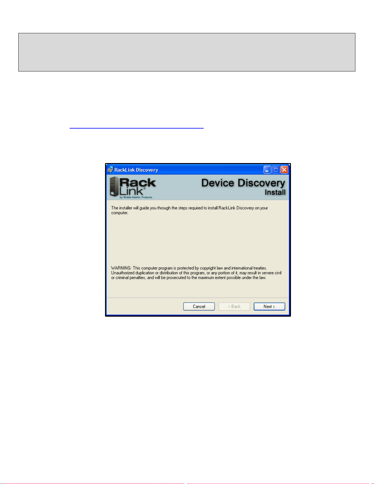
2. Download and run the RackLink Device Discovery setup.exe file.
The Device Discovery Setup dialog box appears.
3. Click Next.
Page 13
Page 14
INSTALLING THE DEVICE DISCOVERY SOFTWARE AND ACCESSING A CONNECTED RACKLINK’S BROWSER-
BASED INTERFACE
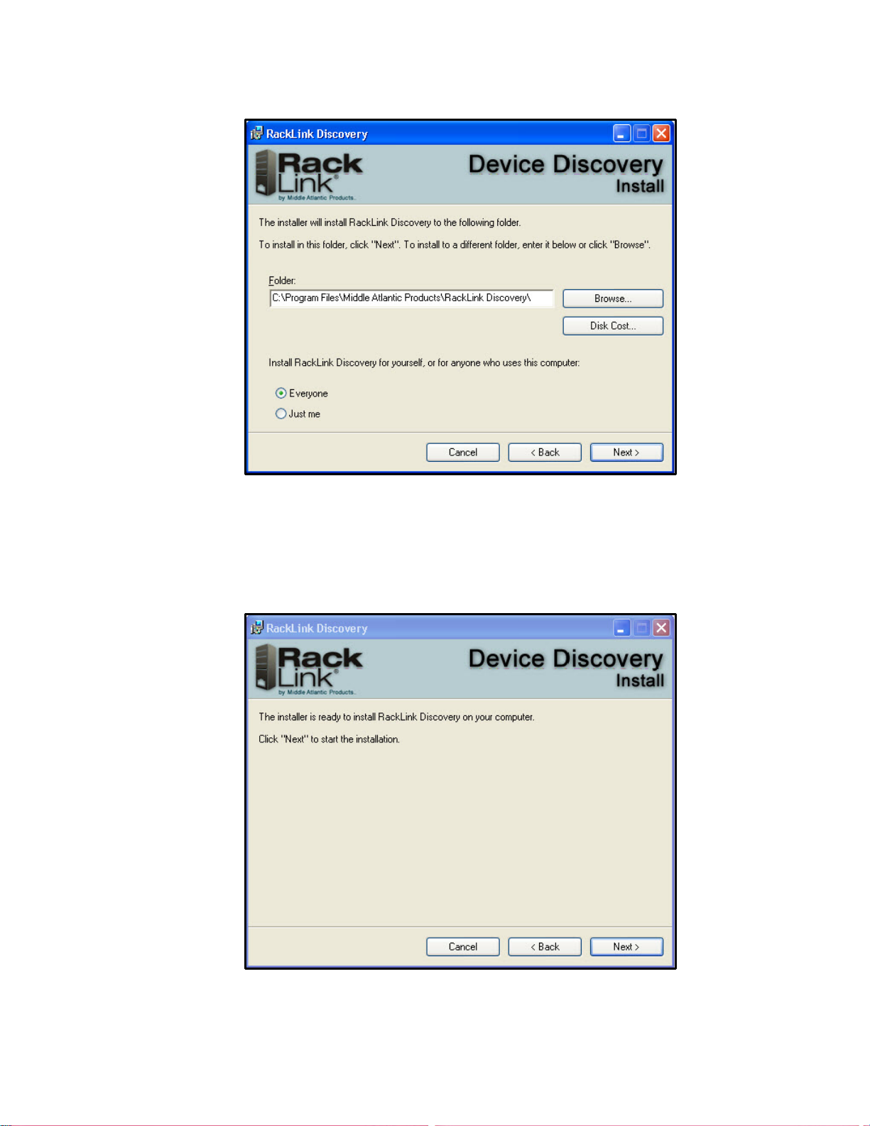
Additional instal l ati on opti ons appear.
4. Click Browse if you wish to change the software installa t ion f older .
If desired, select whether you want to install RackLink Discovery for everyone, or just the
current user.
5. Click Next.
The installer indicates that it’s ready to install RackLink Discovery on your computer.
Page 14
Page 15
INSTALLING THE DEVICE DISCOVERY SOFTWARE AND ACCESSING A CONNECTED RACKLINK’S BROWSER-
BASED INTERFACE
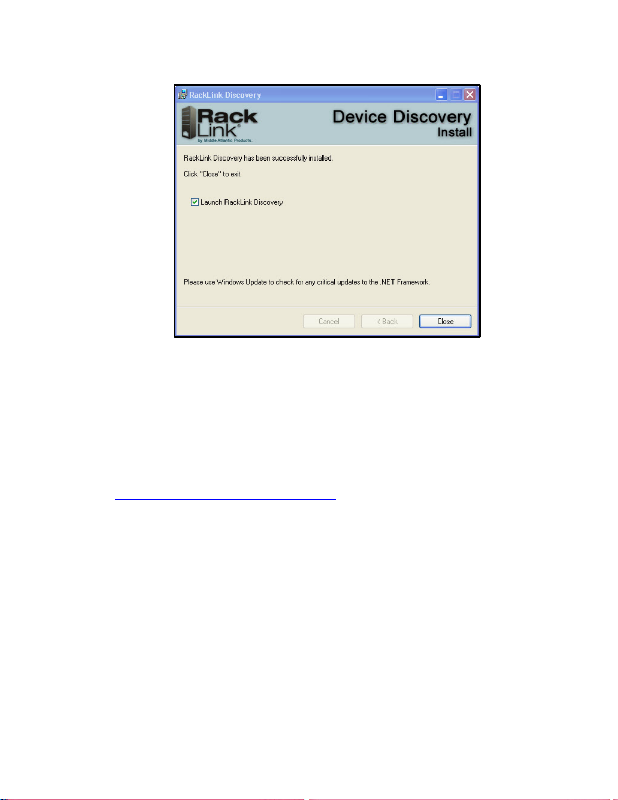
6. Click Next to begin the installation.
The installer indicates that RackLink Discovery has been successfully installed and provides a
default check box selection to Launch RackLink Discovery after closing the installer.
7. Click Close.
Installing the RackLink Device Discovery software on a MAC:
To install RackLink Device Discovery software on a MAC:
1. Access http://www.middleatlantic.com/downloads.
2. Download and run the RackLinkDiscovery.pkg file.
Page 15
Page 16
INSTALLING THE DEVICE DISCOVERY SOFTWARE AND ACCESSING A CONNECTED RACKLINK’S BROWSER-
BASED INTERFACE
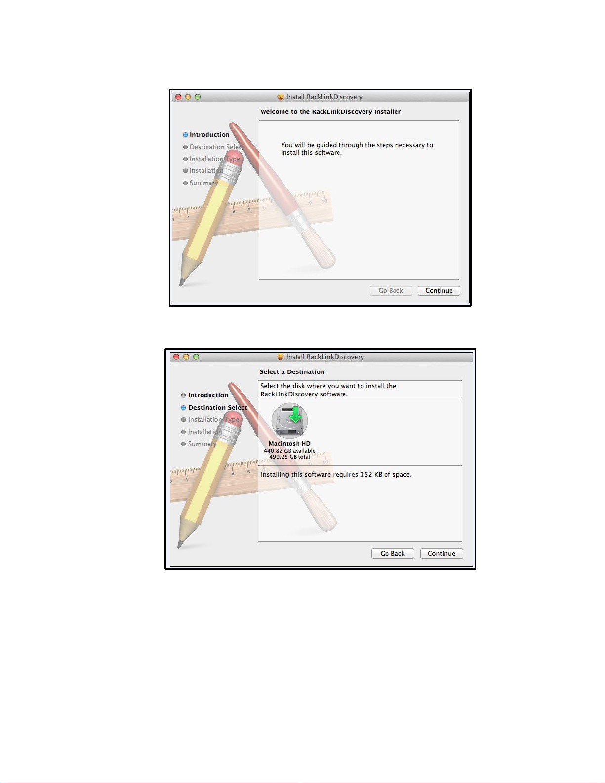
The Device Discovery Setup dialog box appears.
3. Click the disk and modify the location if you wish to change the software installation folder.
4. Click Continue.
Page 16
Page 17
INSTALLING THE DEVICE DISCOVERY SOFTWARE AND ACCESSING A CONNECTED RACKLINK’S BROWSER-
BASED INTERFACE
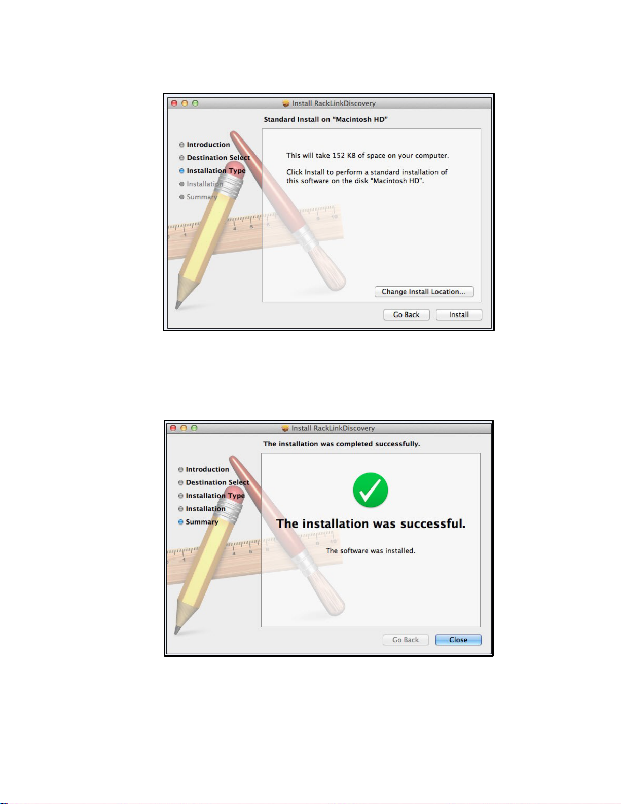
The Installation Type screen appears.
5. Click Change Install Location if you wish to change the software installation folder.
6. Click Install.
7. The installer indicates that the installation was completed successfully.
8. Click Close.
Page 17
Page 18
INSTALLING THE DEVICE DISCOVERY SOFTWARE AND ACCESSING A CONNECTED RACKLINK’S BROWSER-
BASED INTERFACE
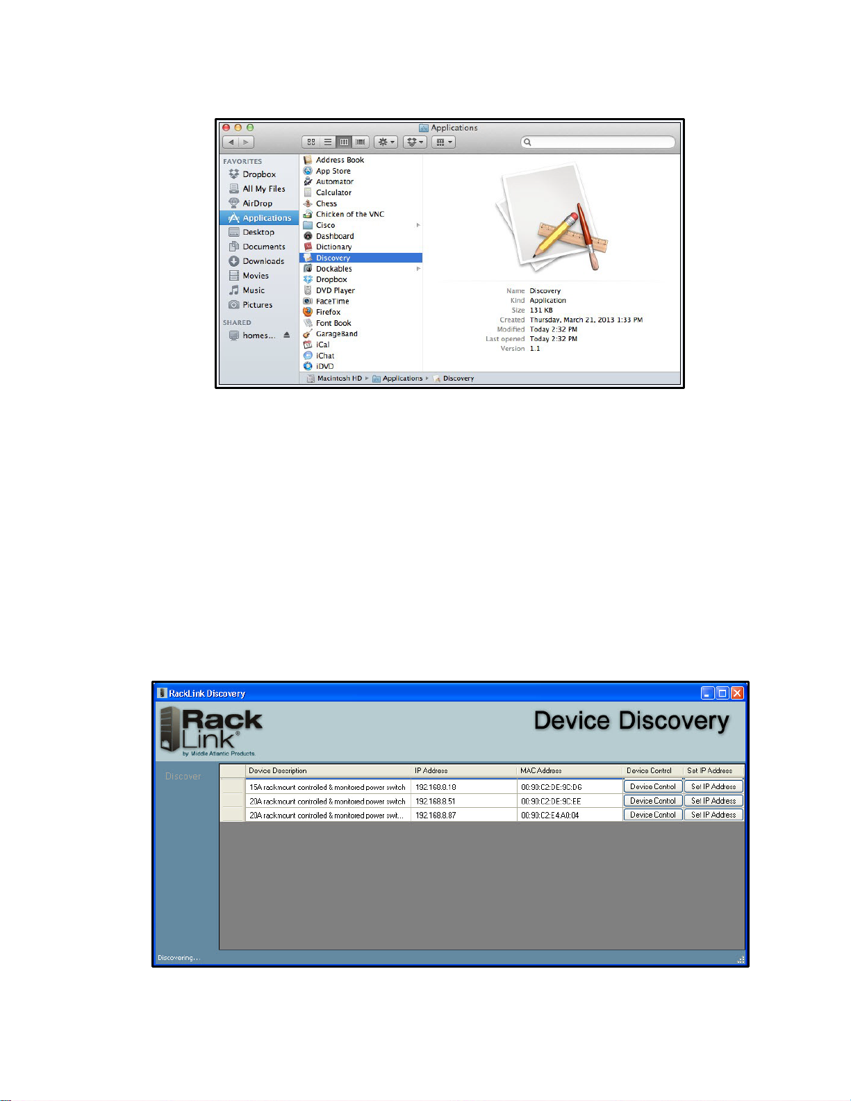
9. Click Applications in the Finder to locate the RackLink Discovery application.
Using Device Discovery
To use device discovery:
1. After launching your RackLink Device Discovery program, the tool automatically discovers all
RackLink devices on the subnet to which you are connected.
Use the Discover button to refresh the screen and discover any newly connected RackLink
devices. By default, the RackLink device is set for DHCP. You can identify each device by the
MAC address or IP address.
NOTE: You may need to disable your Windows firewall to discover your RackLink device.
2. Click Device Control to access the browser-based interface for a specific device.
Page 18
Page 19
INSTALLING THE DEVICE DISCOVERY SOFTWARE AND ACCESSING A CONNECTED RACKLINK’S BROWSER-
BASED INTERFACE
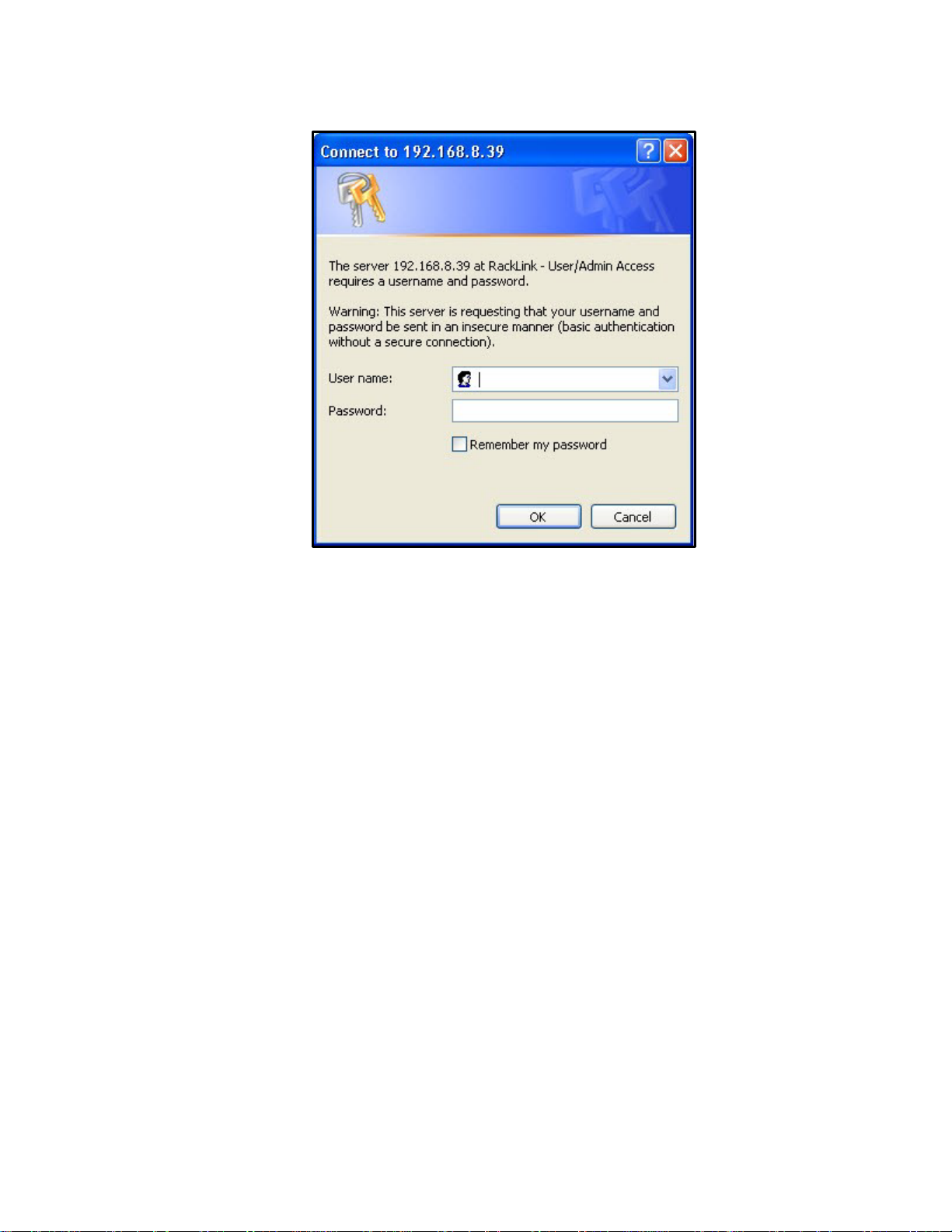
The system prompts you for a username and password.
NOTE:
• To log in with the administrator account, the default credentials are Username: admin
Password: admin.
• To log in with the user account, the default credentials are Username: user Password:
user.
Page 19
Page 20

SETTING UP YOUR RACKLINK DE V ICE FOR THE FIRST TIME
Out of the box, your RackLink device is configured to use DHCP. If you are using a DHCP server,
your RackLink device should work automatically and you can skip to “Using the Browser-Based
Interface” on page 29. If you are not using a DHCP server, use the following procedures to configure
your RackLink device using a static TCP/IP address.
The following items are requi r ed:
• A RackLink device.
• A network crossover cable (Cat 5 or better ) .
• A standard network cable (Cat 5 or better).
• A pen and paper.
NOTE: The following procedure show s steps usi ng Windows 7. The setup steps are similar in
other operating sys tem s.
Configuring TCP/IP on Your PC
First configure TCP/IP on your PC, and then configure TCP/IP on your RackLink device via either the
browser-based interface or Device Discovery. For more information, see “Configuring TCP/IP in
RackLink via Browser-Based Interface” on pag e 24 and “Configuring TCP/IP in Ra c k Link via Device
Discovery” on page 25.
To configure TCP/IP on your PC:
1. Disconnect the PC from any networks.
2. Click Start.
Page 20
Page 21
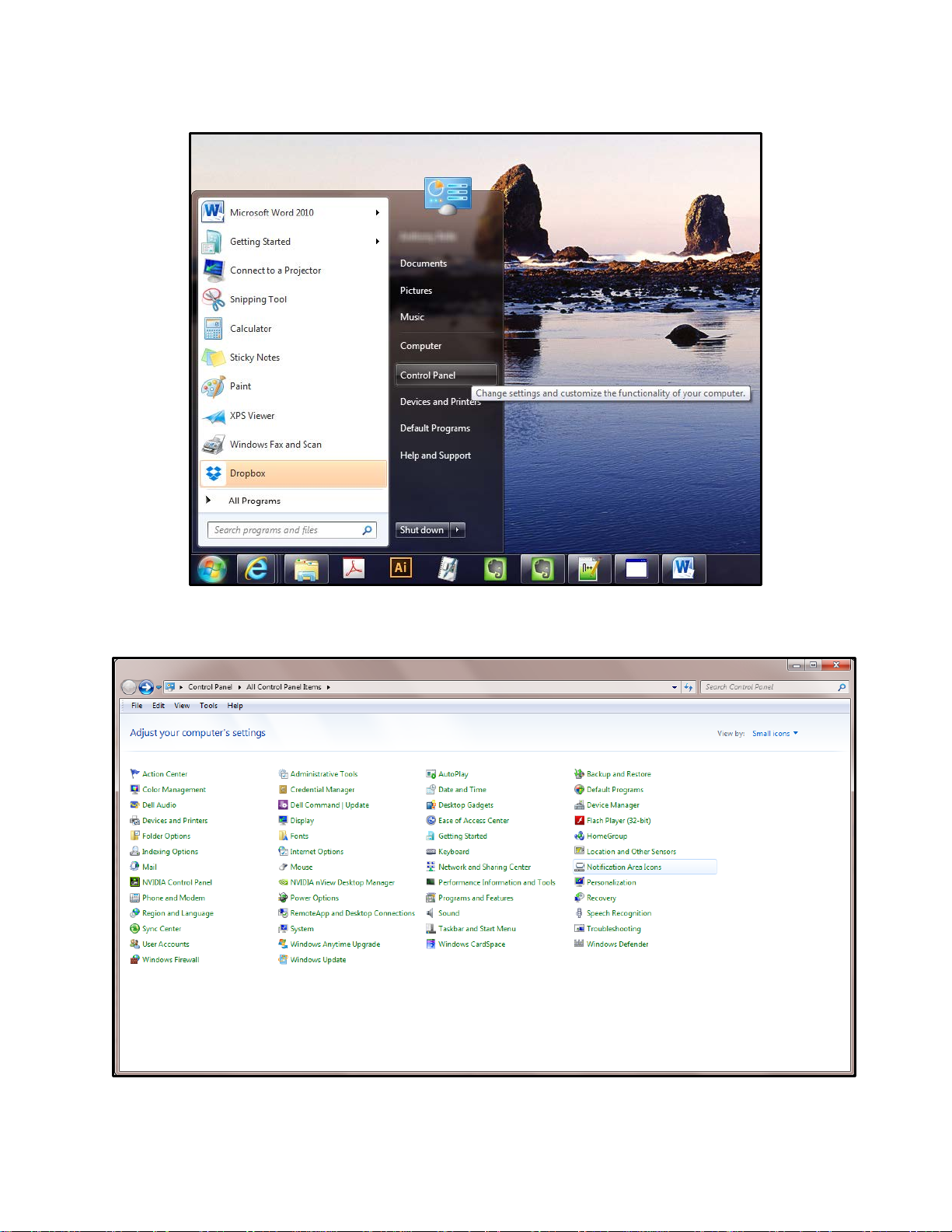
3. Click Control Panel.
SETTING UP YOUR RACKLINK DEVICE FOR THE FIRST TIME
The Control Panel appears.
4. Double click Network Shar i ng Center.
Page 21
Page 22
SETTING UP YOUR RACKLINK DEVICE FOR THE FIRST TIME
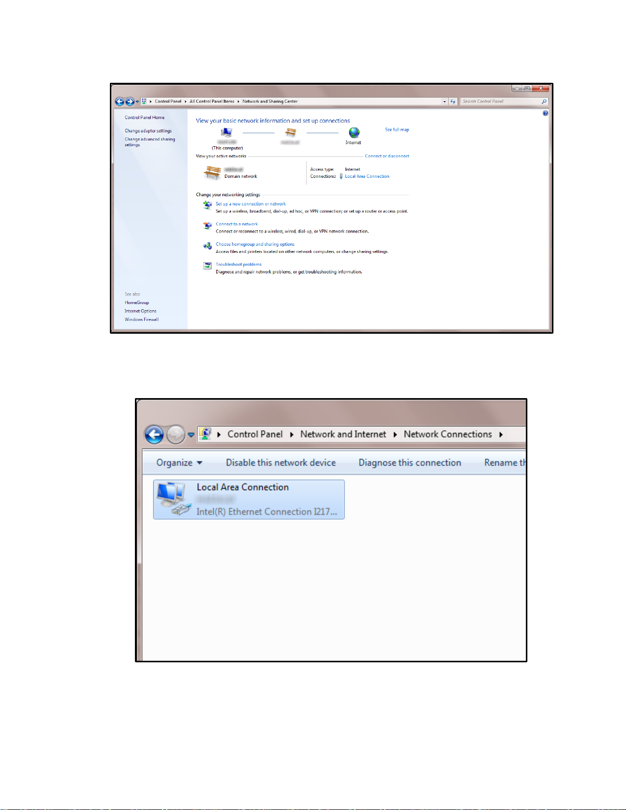
The Network Sharing Center screen appears.
5. Click Change adapter settings.
The Network Settings screen appears.
Locate the computer’s wired network connection, which should be listed in the LAN or HighSpeed Internet group and be named similar to “Local Area Connection.”
Page 22
Page 23

SETTING UP YOUR RACKLINK DEVICE FOR THE FIRST TIME
6. Right-click the wired network connection and select Properties.
The Local Area Connection Properties window appears.
7. Click Internet Protocol Version 4 (TCP/IPv4) to highlight the row.
Page 23
Page 24

8. Click Properties.
The Internet Protocol (IP) Properties window appears.
SETTING UP YOUR RACKLINK DEVICE FOR THE FIRST TIME
9. Write down the computer’s current TCP/IP settings.
NOTE: Save these settings. You will use them to restore the computer back to the original
configuration after your RackLink device is directly connected to your PC.
10. Select Use the following TCP/IP address and configure the fol l owing:
• In the IP address field, enter 192.168.1.201.
• In the Subnet mask field, enter 255.255.255.0.
• In the Default gateway field, enter 192.168.1.200.
11. Click OK.
NOTE: You may need to reboot your PC for the new settings to take effect.
Configuring TCP/IP in RackLink via Browser-Based Interface
First configure TCP/IP on your PC, and then configure TCP/IP on your RackLink device via either the
browser-based interface or Device Discovery. For more information, see “Configuring TCP/IP on Your
PC” on page 20 and “Configuring TCP/IP in RackLink via Device Discovery” on page 25.
Page 24
Page 25

SETTING UP YOUR RACKLINK DEVICE FOR THE FIRST TIME
To configure TCP/IP in RackLink via the brow ser-based interf ace:
1. With your RackLink device still powered off, plug one end of the network crossover cable into
the network jack on the rear of your RackLink device.
2. Plug the other end of the network crossover cable into the PC’s network jack.
3. Plug in and power on your RackLink device.
NOTE:
• After a few seconds, the computer and the RackLink unit should establish a netw or k
connection.
• The RackLink's alert light blinks red when it is attempting to acquire a network address.
The alert light stops blinking once it has a valid TCP/IP address.
4. Open a web browser on the PC (Microsoft Internet Explor er 9 or later is recommended) and
navigate to http://192.168.1.200.
5. Log in to the browser-based interface with the administrator account.
For more information, see “Logging in to the Administrator Settings Menu” on page 42.
6. Click Network.
7. Change the network information to your preferred values for IP Address, Subnet Mask,
Gateway, and DNS Server.
8. Click Save.
NOTE: After these settings have been changed, you no longer can access your RackLink
device from your PC connected via crossover cable.
9. Disconnect the network crossover cable connecting your RackLink device and your PC.
10. Restore the PC to the origi nal TCP/IP settings using the information you wrote down during
“Configuring TCP/IP on your PC” on page 20.
11. Put your RackLink device in its final location.
Configuring TCP/IP via Device Discovery
NOTE: This procedure also shows how to configure TCP/IP via DHCP.
First configure TCP/IP on your PC, and then configure TCP/IP on your RackLink device via either the
browser-based interface or Device Discovery. For more information, see “Configuring TCP/IP on Your
PC” on page 20 and “Configuring TCP/IP in RackLink via Browser-Based Interface” on page 24.
Page 25
Page 26

SETTING UP YOUR RACKLINK DEVICE FOR THE FIRST TIME
To configure TCP/IP in RackLink via D evice Discovery:
1. After launching your RackLink Device Discovery software, the tool automatically discovers all
RackLink devices on the subnet to which you are connected.
Use the Discover button to refresh the screen and discover any newly connected RackLink
devices. By default, the RackLink device is set for DHCP. You can identify each device by the
MAC address or IP address.
NOTE: You may need to disable your Windows firewall to discover your RackLink device.
2. Click Set IP Address.
The RackLink device prompts you for admin credentials.
3. Enter admin/admin.
4. Click Login.
Page 26
Page 27

SETTING UP YOUR RACKLINK DEVICE FOR THE FIRST TIME
The IP settings dialog box appears.
• If you use a DHCP server, leave the DHCP check box selected and continue with the
following steps:
a. Click Apply.
Your RackLink device then acquires an IP address from your DHCP server.
• If you don’t use a DHCP server, Clear the Use DHCP check box and continue with the
following steps:
The text fields on the dialog box change from read only to write.
Page 27
Page 28

SETTING UP YOUR RACKLINK DEVICE FOR THE FIRST TIME
a. Change the network information to your preferred values for IP Address,
Subnet Mask, Gateway, and DNS Server.
b. Click Apply.
5. You may now access the browser-based interface using any of the following ways:
• Click Refresh in the Device Discovery tool.
• Type the IP address into a browser and click Go.
• Click the De vice Control button of the corresponding row of your RackLink device
listed in Device Discovery.
• Double-click anywhere on the corresponding row of your RackLink device listed in
Device Discovery.
Page 28
Page 29

DOWNLOADING AND USING T HE M OBILE APP
The mobile application allows real-time control of any controllable outlet fro m your mo bi l e pho ne.
Download the RackLink app from the Google Play™ store or the App Store®.
Page 29
Page 30

Administrator Account
User Account
Control System Account
admin
admin
user
user
user
password
USING THE BROWSER-BASED INTERFACE
The browser-based interface allows you to control your RackLink device from a PC. You can access
it from the Device Discover y tool or by entering your RackLink device’s IP address in a browser.
Logging in to the Browser-Based Interface
To log in to the browser-based interface:
1. Install and launch your RackLink Discovery software and connect to a RackLink device.
For more information, see “Installing the Device Discovery Software and Accessing a
Connected RackLink’s Br owser-Based Interface” on page 13.
The RackLink device prompts you for credentials.
The defaul t account names and passwords for the Administrator, User, and Control Systems,
respectively, on your RackLink device are as follows:
Username:
Password:
NOTE: The Control System account is only used by control systems to access your RackLink
device. This account is not used to access the browser-based interface.
2. Enter the credentials for the account you wish to use.
3. Click Login.
The Dashboard appears.
Username:
Password:
Page 30
Username:
Password:
Page 31

USING THE BROWSER-BASED INTERFACE
Name and Model
Number
Firmware Version
Administrator
Settings Menu
Every screen of the browser-based interface includes your connected RackLink device’ s name
and model number, and firmware version with the facility code.
NOTE:
• The Administrator Settings menu only appears when logged in using the Admin
account. For more information, see “Configuring Administrator Settings” on page 42.
• Some screenshots have been slightly modified to improve legibility.
• The number of outlets appeari ng on the Dashboard is model specific. For more
information, see “RackLink Select Model Diagrams” on page 62.
• The device name can be modified in the Administrator Settings. For more information,
see “Configuring Administrator Settings” on page 42.
Page 31
Page 32

USING THE BROWSER-BASED INTERFACE
Understanding S ystem C onfi r m ati ons
You’ll notice the fol l owing types of system feedback while interacting with your device via the
Browser-Based Interface.
• Warnings appear as a prompt in the upper, center part of the screen.
• Error notifications appear in a bar that comes down from the top of the screen.
Page 32
Page 33

USING THE BROWSER-BASED INTERFACE
• Messages in a box on the upper-right corner of the screen indicate that an acti on y ou
performed was successful.
• Input validation is performed on all text input fields. The system highlights the field in red and
provides a warning indicating the requirements for submitting a proper text input field value.
Page 33
Page 34

USING THE BROWSER-BASED INTERFACE
Viewing Help Information
To view help information:
1. Install and launch your RackLink Discovery software and connect to a RackLink device.
For more information, see “Installing the Device Discovery Softw are and Accessing a
Connected RackLink’s Br owser-Based Interface” on page 13.
2. Enter the credentials for the account you wish to use. For more information, see “Logging in to
the Browser-Based Interface” on page 30.
3. Click an Information icon.
Corresponding help information appears.
4. Click OK.
Viewing and Configuring Information on the Dashboard
The Dashboard is the main interface and includes Sequence Control, Outlet Control, and Status Log
sections.
Initiating a Sequence
To initiate a sequence:
1. Install and launch your RackLink Discovery software and connect to a RackLink device.
For more information, see “Installing the Device Discovery Software and Accessing a
Connected RackLink’s Br owser-Based Interface” on page 13.
2. Enter the credentials for the account you wish to use. For more information, see “Logging in to
the Browser-Based Interface” on page 30.
3. View the sequence status information as follows:
Page 34
Page 35

USING THE BROWSER-BASED INTERFACE
• View the Status field to see the current sequence state. With sequencing disabled, the
field shows “Not Sequenced”. If sequencing has not been initiated or if any sequenced
outlet has changed state, the field shows “Not Sequenced”. Otherwise, one of the
following statuses appear in this field:
o Sequencing ON in Progress
o Sequencing ON Complete
o Sequencing OFF in Progress
o Sequencing OFF Complete
4. Use the Initiate Sequence buttons to start a sequence as follows:
• Click On or Off to initiate a sequence to activ ate or deact ivate the outlets (depending on
the initial state of the outlets on your RackLink unit).
After selecting On or Off, then adjust the delay.
• In the Delay field, enter a delay value (in seconds) for the amount of time you wish to
elapse between each controlled outlet in the sequence. The set delay time applies to all
sequenced outlets and can be set fro m 0 – seconds.
• Click Initiate after setting the delay.
Configuring Outlet Controls
To configure outlet controls:
1. Install and launch your RackLink Discovery software and connect to a RackLink device.
For more information, see “Installing the Device Discovery Software and Accessing a
Connected RackLink’s Br owser-Based Interface” on page 13.
2. Enter the credentials for the account you wish to use. For more information, see “Logging in to
the Browser-Based Interface” on page 30.
The Dashboard appears.
3. At the top of the Outlet Control section of the screen, the outlet drop-down provides the
following viewing choices:
• Show All Outlets
• Show In Sequence Outlets Only
• Show AutoPing Enabled Outlets Only
• Show Controlled Outlets Only
Page 35
Page 36

USING THE BROWSER-BASED INTERFACE
Controlled
Always On
Controlled
Always On
Controlled
Always On
Controlled
Always On
Always On
Always On
4. Click a controlled outlet under the outlet drop-down to access the following additional outlet
settings:
NOTE: Outlet, Cycle Option, and AutoPing settings all appear on a single outlet dialog. They
are broken into respective parts in this topic for clarity.
• The Number indicates the outlet number on your RackLink device.
• In the Device name field, m odify the device name, as desired.
NOTE: Number and Device name are shown for Always On outlets. Controlled outlets
have additional options as explained in the remainder of this topic.
• Use the On/Off switch to activate or deacti vate the controlled outlet, as desired.
NOTE: Vertical RackLink models (RLNK-1015V and RLNK-1615V) start with a
controlled outlet and then alternate with always on outlets down the unit. The dashboard
shows the alternating controlled outlets. On the RLNK-1015V model, shown below, the
last three outlets are always on .
Page 36
Page 37

USING THE BROWSER-BASED INTERFACE
Controlled
Controlled
Controlled
Controlled
Always On
Always On
Always On
Always On Always On Always On
• Select the Include in Sequence check box to include or exclude the specific controlled
outlet as part of the overall sequence. This option is selected by default.
5. The following cycle option settings appear in the Cycle Options section:
NOTE: Outlet, Cycle Options, and AutoPing settings all appear on a single outlet dialog.
They are broken into respective parts in this topic for clarity.
• In the Cycle Delay field, enter a cycle delay value (1 – 999 seconds with a 3 second
default), as desired.
• Click Start Cycle to cycle the outlet power one time only when the outlet is on.
NOTE: New commands received on a given outlet supersede the cycle command.
Page 37
Page 38

USING THE BROWSER-BASED INTERFACE
6. The following AutoPing settings appear in the AutoPing section:
NOTE:
• Outlet, Cycle Options, and AutoPing settings all appear on a single outlet dialog. They
are broken into respective parts in this topic for clarity.
• AutoPing settings may be used to configure your RackLink device to automatically Ping
another IP address and create actions in the event of a failure.
TIP: For an example AutoPing configuration, see “Understanding an AutoPing Configuration”
on page 56.
• In the Status display field, view the current status of communication between your Ping
device and your RackLink device outlet. You can see the status from the dashboard and
in the outlet details. The statuses and corresponding color indicators include the
following:
o AutoPing Replied (Green text appears.)
o AutoPing Failed (Red text appears.)
o AutoPing not started (White text appears.)
o Attempting communication... (White text appears.)
o Starting AutoPing... (White text appears.)
o Stopping AutoPing... (White text appears.)
o AutoPing Stopped (White text appears.)
o No status (White text appears.)
Page 38
Page 39

USING THE BROWSER-BASED INTERFACE
NOTE: The Alert LED is red if any outlet has a failed AutoPing, or green if all outlets
indicate AutoPing replied.
• In the Enabled field, select to turn AutoPing On or Off for the specific outlet.
• In the IP Address field, enter the IP address of the Ping device.
• In the Frequency field, enter how often (in seconds) your RackLink device initiates an
AutoPing. You can configur e 30 - 999 seconds and the default is 30.
• In the Retries field, enter the number of times your RackLink device will Ping the preset
address if no response is received. You can configure 2 - 200 retries and the default is 3.
For example, using the default settings with a Frequency of 30 seconds and three
Failures, the device being Pinged would need to be offline for 90 seconds before the
recovery action is executed.
• In the Email Enabled field, select to turn email notifications On or Off for the specific
AutoPing from your outlet.
For more information, see “Configuring Email Settings” on page 47.
• In the Recovery Action drop-down field, set a desired outlet action while the configured
Ping device does not reply. The actions cease whenever the Ping device does reply. The
actions include the following:
o Power-cycle Until Recovery
o Power-cycle Once
o Power Off Pending Recovery
o Power Off
o Power On Pending Recovery
o Power On
NOTE: Only one action per outlet can be performed at a time.
• In the Cycle Time field, enter a cycle time delay value (in seconds) for the specific
AutoPing recovery action. You can configure the delay to be between 1 - 999 (inclusive)
seconds and the default is 3.
7. Click Save.
TIP: To restore the default settings, see “Restoring Factory Defaults” on page 49.
NOTE: The Cycle Time option only appears when the Power-cycle Until Recovery action
is selected.
Page 39
Page 40

USING THE BROWSER-BASED INTERFACE
Horizontal Scroll
Circles
Viewing Status Log Infor m ation
To view status log information:
1. Install and launch your RackLink Discovery software and connect to a RackLink device.
For more information, see “Installing the Device Discovery Software and Accessing a
Connected RackLink’s Browser-Based Interface” on page 13.
2. Enter the credentials for the account you wish to use. For more information, see “Logging in to
the Browser-Based Interface” on page 30.
The Dashboard appears.
The Status Log section of the screen includes log entries for events taking place in your
RackLink device.
NOTE: Click the circles to scroll horizontally and access any additional logs.
3. Logs shown on the dashbo ar d provide the following data:
• Date, Time, and Status (of the log event).
Log entry statuses indicate the following reasons:
o Normal Event
o AutoPing Fault
o AutoPing Recovery
4. Click a log entry to view log entry details.
• The date, time and status appear on the details screen.
• The outlet that changed is listed and visually highlighted on the details screen.
• The Room Occupancy field shows the current occupancy status as set by the control
system.
Page 40
Page 41

5. Select the log details view from the following options:
• Select the Outlet Status option to show the state of each outlet at the time of the event.
The highlighted outlet is the one changed by the specific event.
USING THE BROWSER-BASED INTERFACE
The Outlet statuses are as follows:
o On
o Off
• Select the Power Management Status option to view the InfoComm™ Power
Management Statuses at the time o f the ev en t .
The InfoComm Power Management Statuses are as follows:
o On
o Off
Page 41
Page 42

USING THE BROWSER-BASED INTERFACE
Administrator Settings Menu
o Cycle/Standby
o Disconnected
o Unknown
NOTE: For more information about the InfoComm Audiovis ual Sy s tems Ener g y
Management Standard, refer to
http://www.infocomm.org/cps/rde/xchg/infocomm/hs.xsl/32933.htm.
Configuring Administrator Settings
The features on the Administrator Settings menu include Date/Time, Device Settings, Email, Factory
Defaults, Firmware Update, Network, and Passwords.
Logging in to the Administ ra t or S e t ti ngs Me nu
NOTE: The Administrator Settings menu is only accessible when logged in using the Admin account.
If you are logged into the User account, the Administrator Settings menu is shown in the upper-right
Page 42
Page 43

USING THE BROWSER-BASED INTERFACE
corner of the screen, however, you are prompted to log in using the Admin account when any of the
options are clicked.
To log in to the administrator settings menu:
1. Install and launch your RackLink Discovery software and connect to a RackLink device.
For more information, see “Installing the Device Discovery Software and Accessing a
Connected RackLink’s Br owser-Based Interface” on page 13.
2. Log in using the Adm in account to access the Administrator Settings menu. For more
information, see “Logging in to the Browser-Based I nt er fac e” on pag e 42.
The Dashboard appears.
3. You can now access the Administrator Settings menu on the upper-right side of the screen.
NOTE: When you select Administrator Setting menu items, corresponding screens fly-in from
the left side of the Dashboard.
Configuring Date/Tim e Sett ings
To configure date/time settings:
1. Install and launch your RackLink Discovery software and connect to a RackLink device.
For more information, see “Installing the Device Discovery Software and Accessing a
Connected RackLink’s Br owser-Based Interface” on page 13.
Page 43
Page 44

USING THE BROWSER-BASED INTERFACE
2. Log in using the Adm in account to access the Administrator Settings menu. For more
information, see “Logging in to the Browser-Based I nt er fac e” on pag e 42.
3. Click Date/Time on the Administrator Settings menu.
The Date/Time Settings screen appears.
4. The Local Date/Time section of the screen displays the current date and time.
5. Select the Enable Daylight Saving check box to enable daylight saving ti me, if desired .
6. The Configuration area of the screen includes the fol l owing:
a. In the Time Zone drop-down, select your desired North American time zone.
b. Selecting NTP or Manual produces different fields as follows:
• Select NTP and the NTP Server URL field rem ains. Specify an NTP server
address of your choice. (The default is pool.ntp.org).
Page 44
Page 45

USING THE BROWSER-BASED INTERFACE
• Select Manual and the Date and Time fields app ear while the NTP Server URL
field is removed. Specify a date and time as desired.
7. Click Save.
TIP: To restore the default settings, see “Restoring Factory Defaults” on page 49.
Configuring Device Settings
To configure device settings:
1. Install and launch your RackLink Discovery software and connect to a RackLink device.
For more information, see “Installing the Device Discovery Software and Accessing a
Connected RackLink’s Br owser-Based Interface” on page 13.
2. Log in using the Adm in account to access the Administrator Settings menu. For more
information, see “Logging in to the Browser-Based I nt er fac e” on pag e 42.
3. Click Device Settings on the Administrator Settings menu.
Page 45
Page 46

The Device Settings screen appears.
USING THE BROWSER-BASED INTERFACE
4. Configure the Device Settings screen as fol lows:
• In the Device Name field, enter your desired name for your RackLink device. This value
appears in the top of the brows er-based interface and is shown in the RackLink Discovery
Tool.
• In the Account Name/Number field you may enter a user-defined value for your own
reference.
• In the Device Description field, you may provide a description for your RackLink device.
• In the Location field, specify a particular location where your RackLink device is kept.
• In the Initial Outlet State drop down, select from the following values :
o Select Remember prior state to have the outlets remain in their prior state
o Select OFF to have the outlets Off during power up as their default setting.
o Select ON to have the outlets On during power up as their default setting.
NOTE: This setting is only applicable to outlets that are not included in sequencing or when
Sequence on Power Up is Off. On is the factory default setting for an outlet.
For more information about which outlets are included or excluded from sequencing, see
“Configuring Outlet Controls” on page 35.
• Turn Sequence on Power Up On or Off to determine whether or not your RackLink device
will perform a sequence while powering up. The default setting is On.
Page 46
Page 47

USING THE BROWSER-BASED INTERFACE
For more information about which outlets are included or excluded from sequencing, see
“Configuring Outlet Controls” on page 35.
5. Click Save.
TIP: To restore the default settings, see “Restoring Factory Defaults” on page 49.
Configuring Email Set ti ngs
NOTE: If you use Gmail and have two-step verification configured, you’ll need to create an app
password to give your RackLink device permission to access the account. For more information, refer
to Google at https://support.google.com/accounts/answer/185833?hl=en.
To configure email settings:
1. Install and launch your RackLink Discovery software and connect to a RackLink device.
For more information, see “Installing the Device Discovery Software and Accessing a
Connected RackLink’s Br owser-Based Interface” on page 13.
2. Log in using the Adm in account to access the Administrator Settings menu. For more
information, see “Logging in to the Browser-Based I nt er fac e” on pag e 42.
3. Click Email on the Administrator Settings menu.
The Email screen appears.
Page 47
Page 48

USING THE BROWSER-BASED INTERFACE
4. Configure the Server Settings section of the screen as follows:
• In the Server’s IP/Host Name field, enter the IP or host name of your mail server.
• In the Sender’s E-mail Address field, enter the em ail address to appear as the “from ”
address in emails sent by your RackLink device.
• In the Port field, enter the port you wish to use on your mail server. The default port is 25.
NOTE:
o Ensure that the server name you provide is a fully qualified domain name.
o Verify you are using the correct port number and verify that your network is not
blocking outbound traffic on the port.
• Select the SSL/TLS check box if you wish to use SSL/TLS encryption on your server.
5. Select the Authentication check box if you wish to require Authentication on your mail server.
This enables the follow ing fields:
• In the Username field, enter the user name on your mail server.
• In the Password field, enter the password on your mail server.
• In the Confirm Password field, confirm the password on your mail server.
• Select the Show Password check box to remove masking dots and show the password
characters as you type them.
6. Click Add A New Recipient beneath the Recipients section of the screen to show the
following fields:
• Provide Name and Email Address information for up to 5 email recipients.
• Click Remove to delete any of the email recipients you ent er ed.
• Edit Name and Email text and click Save as desired.
Page 48
Page 49

USING THE BROWSER-BASED INTERFACE
• Status information appears under corresponding email recipients for the following events:
PASS
o Success. Email Sent.
FAIL
o Failure code ###. SMTP Server could not be resolved.
o Failure code ###. The SMTP server connection failed or was
prematurely terminated.
o Failure. The SMTP return code was ###.
NOTE: Click the question mark to the right of each status to display its additional
information.
• Click Send Tes t Email to send a test email to each recipient you’ve saved in the system.
This is done to ensure your email alert system is working properly.
7. Click Save.
TIP: To restore the default settings, see “Restoring Factory Defaults” on page 49.
Restoring Factory Defaults
NOTE: The Factory Reset button on your RackLink unit resets to DHCP and default passwords. For
more information, see “RackLink Select Model Diagrams” on page 64.
You can restore the factory default settings for diff erent areas of your RackLink device as follow s :
• Restore Event Log
• Restore AutoPing Defaults
Page 49
Page 50

USING THE BROWSER-BASED INTERFACE
• Restore Date/Time Defaults
• Restore Device Setting Defaults
• Restore Email Defaults
• Restore Password Defaults
• Restore Sequencing Defaults
• Restore Network Defaults
To restore factory defaults:
1. Install and launch your RackLink Discovery software and connect to a RackLink device.
For more information, see “Installing the Device Discovery Software and Accessing a
Connected RackLink’s Br owser-Based Interface” on page 13.
2. Log in using the Adm in account to access the Administrator Settings menu. For more
information, see “Logging in to the Browser-Based I nt er fac e” on pag e 42.
3. Click Factory Defaults on the Administrator Settings menu.
The Load Default Settings screen appears.
4. Select the default setting check boxes for the items you wish to restore on your RackLink
device. Select the All check box to mark them all with a single click.
5. Click Save.
TIP: To restore the default settings, see “Restoring Factory Defaults” on page 49.
Page 50
Page 51

USING THE BROWSER-BASED INTERFACE
Updating Device Firmware
To update device firmware:
1. Install and launch your RackLink Discovery software and connect to a RackLink device.
For more information, see “Installing the Device Discovery Software and Accessing a
Connected RackLink’s Br owser-Based Interface” on page 13.
2. Log in using the Adm in account to access the Administrator Settings menu. For more
information, see “Logging in to the Br owser-Based Interface” on page 42.
3. Click Firmware on the Administrator Setti ng s men u.
The Firmware screen appears.
4. View the Current Firmware Version for the number of the latest firmware installation.
5. Click Choose File to locate a newer firmware version file you wish to upload to your RackLink
device.
6. After choosing a file, the file Name, Size, and a Transfer Status bar appear, and the Upload
button is enabled.
7. Click Upload.
8. The Transfer Status bar prog r es ses and indi cates a percentage. The status then changes to
Finalizing until indicating Transfer Successful.
Page 51
Page 52

USING THE BROWSER-BASED INTERFACE
9. After the transfer completes, the Restart button appears and the system indicates an upload
reminder that the “Unit will sequence down, install the new firmware, and return to the main
page.”
10. Click Restart.
A message then appears indicating “Sequencing down the device and updating its firmware.
This page will reload in: XX seconds…”
NOTE:
• The unit will sequence down, install the new firmware version, and then power back up.
• The Alert LED blinks green while the system restarts. Do not power down your unit during
the system restart.
Page 52
Page 53

USING THE BROWSER-BASED INTERFACE
11. When the dashboard appears, confirm that the firmware version is correct.
Configuring Network Settings
To configure network settings:
1. Install and launch your RackLink Discovery software and connect to a RackLink device.
For more information, see “Installing the Device Discovery Software and Accessing a
Connected RackLink’s Br owser-Based Interface” on page 13.
2. Log in using the Adm in account to access the Administrator Settings menu. For more
information, see “Logging in to the Browser-Based I nt er fac e” on pag e 42.
3. Click Network on the Administrator Settings menu.
Page 53
Page 54

The Network screen appears.
USING THE BROWSER-BASED INTERFACE
4. The MAC Address displays the unique MAC Address of your specific RackLink device.
5. Use DHCP or configure your IP settings manually as follows:
• Select the DHCP check box to use a DHCP server for configuring all IP address
settings.
• Clear the DHCP check box to configure the following IP settings manually:
o Device IP Address
o Subnet Mask
o Gateway
o DNS1 (Primary DNS)
o DNS2 (Secondary DNS, Optional)
6. In the HTTP Port field, provide your desired port value. Port 80 is set as the default. You may
not change value to a port that is already in use. Ports used by the system include 7
(ICMP/Ping), 443 (HTTPS), 54632 (Discovery), and 60000 (Contr ol Pr otoc ol) . If you choose
any of these ports, the system will not change the port of the HTTP Server.
7. Click Save.
Page 54
Page 55

USING THE BROWSER-BASED INTERFACE
NOTE: The Alert LED blinks green while acquiring an IP Address. If the device does not
receive a DHCP request after 30 seconds, it will default to 192.168.1.200 and the Alert LED
alternates between red and green.
TIP: To restore the default settings, see “Restoring Factory Defaults” on page 49.
Passwords
When logged in to the browser-based interface using the Admin account, you can change the
passwords for the User, Admin, and Control Systems accounts.
NOTE:
• For default account names and passwords, see “Logging in to the Browser-Based Interface”
on page 30.
• While passwords may be changed by the administrator, account names are fixed and cannot
be changed.
To configure new passwords:
1. Install and launch your RackLink Discovery software and connect to a RackLink device.
For more information, see “Installing the Device Discovery Software and Accessing a
Connected RackLink’s Br owser-Based Interface” on page 13.
2. Log in using the Adm in account to access the Administrator Settings menu. For more
information, see “Logging in to the Browser-Based I nt er fac e” on pag e 42.
3. Click Passwords on the Administrator Settings menu.
Page 55
Page 56

The Passwords screen appears.
USING THE BROWSER-BASED INTERFACE
4. Enter and confirm the passwords to change the Administrator, User, and Control System
accounts, as desired.
5. Select the Show Password check box to display the actual characters in corresponding text
boxes.
6. Click Save.
TIP: To restore the default settings, see “Restoring Factory Defaults” on page 49.
Page 56
Page 57

UNDERSTANDING AN AUTOP ING CONFIGURATION
This section takes you through an AutoPing configuration where your RackLi nk reb oots a
modem/router in the evet that its Internet connection stops working.
NOTE:
• A proper AutoPing configuration prevents cyclic outlet rebooting. Cyclic outlet rebooting is the
result of AutoPing settings not taking the modem/router’s start-up time into account. T hi s
results in your RackLink continuously turning the controlled outlet on and off.
• Understand that email notifications are not received in the event that your Internet connection
goes down. Instead, a recovery notification is sent when the connection is reestablished. Refer
to the log entry for more information about when the actual failure occurred. For more
information, see “Viewing Status Log Information” on page 40.
Connecting Your Equipment
This picture shows the following connections you should make to your equipment:
• Connect your modem/router’s (black box above the RackLink) power cable into a controlled
outlet on the RackLink.
• Connect your RackLink’s Ethernet cable (blue) into switch port 1 on the modem/router.
• Connect your modem/router to the Internet (yellow cable).
Page 57
Page 58

UNDERSTANDING AN AUTOPING CONFIGURATION
Measuring Modem/Router Start-Up Time
When conf iguring AutoPing, it’s important to know the start-up time of the modem/router. The start-up
time is the amount of time between when the modem/router is powered-up until it starts routing traffic
to the Internet.
NOTE: If your Internet connection is down from your Internet Service Provider (ISP) or your AutoPing
settings don’t take your modem/router’s start-up time into account, the result is referred to as Cyclic
Rebooting, where your RackLink continuously turns the controlled outlet on and off.
To measure your modem/router start-up time:
1. Leave your modem/router unplugged/powered off.
2. Open a command prompt and Ping an address on the internet using the –t option (Ping
continuously) as foll ows:
ping –t www.google.com
You should see replies indicating “Request timed out”.
3. Start a stopwatch while plugging in the modem/router’s power cable.
Once you see “Reply from…” as a response, stop the stopwatch.
This is your start-up time for the mod e m/r out er .
NOTE: It may be beneficial to add a few seconds to the start-up time just to be safe. For our
example, we will assume the modem/router boots up in about 2 minutes.
Calculating Frequency, Failures, and Cycles
Before configuring AutoPing in your RackLink device, it’s important to understand the relationship
between Frequency, Failures, and Cycles. It is good practice to keep the default values for Frequency
and Failures (30 and 3, respectively) and adjust your outlet recovery cycle time (Cycle-Time) to equal
your measured recovery time from “Measuring Modem/Router Start-Up Time” on page 58, plus at
least 1 frequency.
In our example, we set Frequency to 30 seconds, Failures to 3, which results in your Internet
connection being down for 90 seconds in order to trigger an AutoPing recovery. Finally, we set an
outlet Cycle-Time of 150 seconds (a modem/router reboot of 120 seconds + a Frequency of 30
seconds).
Page 58
Page 59

UNDERSTANDING AN AUTOPING CONFIGURATION
Configuring AutoPing in Your RackLink
For more general AutoPing information, see “Configuring Outlet Controls” on page 35; otherwise,
continue here with this example configuration.
To configure AutoPing in your RackLink:
1. Install and launch your RackLink Discovery software and connect to a RackLink device.
For more information, see “Installing the Device Discovery Software and Accessing a
Connected RackLink’s Br owser-Based Interface” on page 13.
2. Enter the credentials for the account you wish to use. For more information, see “Logging in to
the Browser-Based Interface” on page 30.
The Dashboard appears.
3. Make the following configurations on a controlled outlet.
Page 59
Page 60

UNDERSTANDING AN AUTOPING CONFIGURATION
• You can configure the IP Address to Ping Google’s DNS server at 8.8.8.8. However,
this address could be the outside interface of your router or your next hop to the
Internet. Find your next hop to the Internet by issuing the following at the command
prompt:
tracert www.google.com
The next hop is the first address that is not internal or private. In this screenshot, the
next hop is 65.122.56.65.
• Configure the Frequency.
This is the time (in seconds) between each Ping. You can set it as short as 30 seconds.
More frequent Pings mean that your RackLink device will respond to outages quicker.
However, more frequent Pings does increase your network traffic and may have an
adverse effect on your network throughput.
• Configure the Failures to 3. With a Frequency of 30 seconds and 3 Failures, the device
being Pinged would need to be offline for 90 seconds before the recovery action is
executed.
• Configure the Recovery to “Power-Cycle Until Recovery”. This results in the outlet
continuously cycling until an Internet connection is reestablished.
• Configure the Cycle-Time for your power cycle delay to 150 seconds.
NOTE: We are using 150 seconds because we assumed our start-up time to be 2
minutes and a Frequency of 30 seconds. For more information, see “Calculating
Frequency, Failures, and Cycles” on page 58.
Page 60
Page 61

UNDERSTANDING AN AUTOPING CONFIGURATION
Our configuration will begin cycling the controlled outlet after 90 seconds (Frequency is
30 seconds and Failures are 3) of no respon s e fro m addres s 65.122.56.65.
The following diagram shows each step of our example AutoPing.
Page 61
Page 62

FREQUENTLY ASKED QUESTIONS
General Questions
Question: What if I forget my password?
Answer: Press the Factory Reset button on the device. This defaults the permissions to
admin/admin. For more information, see “RackLink Select Model Diagrams” on page 64.
NOTE: If you have configured your RackLink to use TCP/IP, resetting the system restores it to using
DHCP. For more information, see “Setting Up Your RackLink Device for the First Time” on page 20.
Question: What if my RackLink device is inoperable after I perform a firmware upgrade?
Answer: Contact Middle Atlantic Products Technical Support at 1-800-266-7225.
Question: What if my RackLink device is not receiving power?
Answer: Ensure that the IEC connector on the line cord is fully inserted into the rear outlet and the
line cord retention clip is securely fastened. Confirm that the circuit breaker is in the ON position. Plug
another device into the exact same outlet your RackLink device was using and see if the other device
functions.
Connectivity Questions
Question: I connected RackLink to my network, but I can’t find it in the Device Discovery program.
What’s wron g?
Answers: The Device Discovery program can only find RackLink devices that are on the same
subnet as the computers accessing them.
• If you are using a DHCP connection, and your RackLink device is unable to obtain an IP
address from the DHCP server, set your computer’s IP address to 192.168.1.xxx. Where xxx
is any number between 1 and 199 or 201 to 254. Your RackLink will default its IP address to
192.168.1.200 and connect with your PC.
• If you are using a TCP/IP connection, consider the following scenario:
If your PC has an IP address of 192.168.1.50 and a subnet mask of 255.255.255.0, and your
RackLink has an IP address of 192.168.2.50 and a subnet mask of 255.255.255.0, the
RackLink will not be listed in the Device Discovery program. This is because the third octets of
the IP addresses (1 and 2, respectively) differ. With a subnet mask of 255.255.255.0, t he fir s t
three octets of the IP addresses on the PC an d Rack Link w ould have to match.
Page 62
Page 63

FREQUENTLY ASKED QUESTIONS
Alert LED State
What It Means
For more information regarding IP addresses, refer to Microsoft’s TechNet articles at
http://technet.microsoft.com/en-us/library/cc958829.aspx.
Question: What could be wrong if I can’t access the browser-based interface?
Answer: Check to see if you can access any webpage. Verify that the Ethernet port’s LEDs on the
back of your RackLink device are solid yellow and blinking green. Review the procedures in “Setting
Up Your RackLink Device for the First Time” on page 20.
Control System Questions
Question: I press the Factory Reset button and reset my RackLink to factory defaults, but I’m getting
a login denied response from RackLink when I sign in using the default Control Systems account and
password. Why is this happening?
Answer: Earlier versions of RackLink firmware did not reset the Control Systems account password
after pressing the Default Restoration button. Reset it manually by accessing the Passwords screen
and setting the Control Systems account password to match your Control System.
Question: Every time I send a command from my control system to my RackLink it responds with a
“Bad Length” error. Why is this happening?
Answer: The length byte is in Hexadecimal format. When you add up the total command length,
make sure you convert the length from decimal format to hexadecimal format.
Question: Every time I send a command from my control system to m y RackLink it responds with a
“Bad Checksum” error. Why is this happening?
Answer: Review the Checksum section of the Serial Communication Protocol document on the
website. Make sure to AND the sum with 127 (0x7F) or modulus the sum with 128 (0x80).
Alert LED States
Question: What are the different statuses for the Alert LED?
Answer:
Blinking Green Acquiring IP address (during startup).
Green Normal operation, IP acquired, and no alarms.
Blinking Green/Red No alarms, running on default IP (DHCP not acquired).
Blinking Red Lost IP connection.
Red Network is active, alarms present.
Page 63
Page 64

1
2
RACKLINK SELECT MODEL DIAGRAMS
RLNK-215 Diagrams
The following front and rear views of the RLNK-215 include callouts that correspond to numbered
descriptions.
RLNK-215 Front View
1. Two Controlled Outlets
2. Integrated Controlled Outlet ON/OFF LED: The LED illuminates green when outlet is
energized.
NOTE: Each controlled outlet has an associated LED. The LED number corresponds with the
numbered controlled outlet.
Page 64
Page 65

RLNK-215 Rear View
3 6 4
5
RACKLINK SELECT MO D EL DIAG RAMS
3. IEC C14 Power Input: 120V nominal, 12A (total load, all outlets), 60Hz input with cord retainer.
4. Factory Reset Button: Resets to DHCP and default passwords. For more information, see
“Configuring Network Settings” on page 47 and “Passwords” on page 55.
5. Alert LED: The LED illuminates red when an alarm condition occurs (any AutoPing failure). For
more information, see “Configuring SMTP Settings” on page 47.
6. Ethernet Port (10/100): Used to connect to a network, requires a Cat-5 (or better) cable.
RLNK-415R Diagrams
The following front and rear views of the RLNK-415R include callouts that correspond to numbered
descriptions.
Page 65
Page 66

RACKLINK SELECT MO D EL DIAG RAMS
4 1 3
8 5 6 2 7
RLNK-415R Front View
1. Controlled Outlet
2. Alert LED: The LED illuminates red when an alarm condition occurs (any AutoPing failure). For
more information, see “Configuring SMTP Settings” on page 47.
3. Integrated Controlled Outlet ON/OFF LEDs: The LED illuminates green when outlet is
energized.
NOTE: Each controlled outlet has an associated LED. The LED number corresponds with the
numbered controlled outlet.
4. Integrated Power Switch/Circuit Breaker
RLNK-415R Rear View
5. IEC C14 Power Input: 120V nominal, 12A (total load, all outlets), 60Hz input with cord retainer.
6. Three Controlled Outlets
7. Factory Reset Button: Resets to DHCP and default passwords. For more information, see
“Configuring Network Settings” on page 47 and “Passwords” on page 55.
8. Ethernet Port (10/100): Used to connect to a network, requires a Cat-5 (or better) cable.
Page 66
Page 67

RACKLINK SELECT MO D EL DIAG RAMS
4 1 8 5 6
3 2 7
RLNK-915R Diagrams
The following front and rear views of the RLNK-915R include callouts that correspond to numbered
descriptions.
RLNK-915R Front View
1. Switched Outlet: Controlled by the main power switch.
2. Alert LED: The LED illuminates red when an alarm condition occurs (any AutoPing failure). For
more information, see “Configuring SMTP Settings” on page 47.
3. Integrated Controlled Outlet ON/OFF LEDs: The LED illuminates green when outlet is
energized.
NOTE: Each controlled outlet has an associated LED. The LED number corresponds with the
numbered controlled outlet.
4. Integrated Power Switch/Circuit Breaker
RLNK-915R Rear View
5. IEC C14 Power Input: 120V nominal, 12A (total load, all outlets), 60Hz input with cord retainer.
6. Eight Controlled Outlets
7. Factory Reset Button: Resets to DHCP and default passwords. For more information, see
“Configuring Network Settings” on page 47 and “Passwords” on page 55.
8. Ethernet Port (10/100): Used to connect to a network, requires a Cat-5 (or better) cable.
Page 67
Page 68

RACKLINK SELECT MO D EL DIAG RAMS
2
1
4 3 5 6 7 9 8
RLNK-1015V Diagrams
The following bottom and top views of the RLNK-1015V include callouts that correspond to numbered
descriptions.
RLNK-1015V Bottom View
1. Ground/Bond Stud
2. Circuit Breaker
RLNK-1015V Front View
3. IEC C14 Power Input: 120V nominal, 12A (total load, all outlets ) , 60 H z input with cord retainer.
4. Integrated Controlled Outlet ON/OFF LEDs: The LED illuminates green when outlet is
energized.
NOTE: Each controlled outlet has an associated LED. The LED number corresponds with the
numbered controlled outlet.
5. Alert LED: The LED illuminates red when an alarm condition occurs (any AutoPing failure). For
more information, see “Configuring SMTP Settings” on page 47.
6. Ethernet Port (10/100): Used to connect to a network, requires a Cat-5 (or better) cable.
7. Controlled Outlets
8. Switched Outlets: Energized by the main power swit ch.
9. Factory Reset Button: Resets to DHCP and default passwords. For more information, see
“Configuring Network Settings” on page 47 and “Passwords” on page 55.
Page 68
Page 69

RACKLINK SELECT MO D EL DIAG RAMS
2
1
RLNK-1615V Diagrams
The following bottom a nd top views of the RLNK-1615V include callouts that correspond to numbered
descriptions.
RLNK-1615V Bottom View
1. Ground/Bond Stud
2. Circuit Breaker
Page 69
Page 70

RACKLINK SELECT MO D EL DIAG RAMS
4 7 6
3 8 5
RLNK-1615V Front View
3. Integrated Controlled Outlet ON/OFF LEDs: The LED illuminates green when
outlet is energized.
NOTE: Each controlled outlet has an associated LED. The LED number
corresponds with the numbered controlled outlet.
4. Sixteen outlets alternate upward from controlled to switched, respectively.
5. IEC C14 Power Input: 120V nominal, 12A (total load, all outlets ) , 60 H z input
with cord retainer.
6. Ethernet Port (10/100): Used to connect to a network, requires a Cat-5 (or
better) cable.
7. Factory Reset Button: Resets to DHCP and default passwords. For more
information, see “Configuring Network Settings” on page 47 and
“Passwords” on page 55.
8. Alert LED: The LED illuminates red when an alarm condition occ ur s (any
AutoPing failure). For more information, see “Configuring SMTP
Settings” on page 47.
Page 70
Page 71

WARRANTY
For warranty information, refer to http://www.middleatlantic.com/company/about-us.aspx#warranty.
Corporate Headquarters
Corporate Voice: 973-839-1011 – Fax: 973-839-1976 / International Voice: +1 973-839-8821 –
Fax: +1 973-839-4982
www.middleatlantic.com – info@middleatlantic.com
Middle Atlantic Canada
Voice: 6 13-836-2501 – Fax: 613-836-269 0 / ca.midd lea tlan ti c.co m – customerservicecanada@middleatlantic.ca
Factory Distribution
USA: NJ – CA – IL Canada: ON - BC
At Middle Atlantic Products we are always listening. Your comments are welcome.
Middle Atlantic Products is an ISO 9001 and ISO 14001 Registered Company.
Page 71
 Loading...