

Page 1
Instruction Sheet
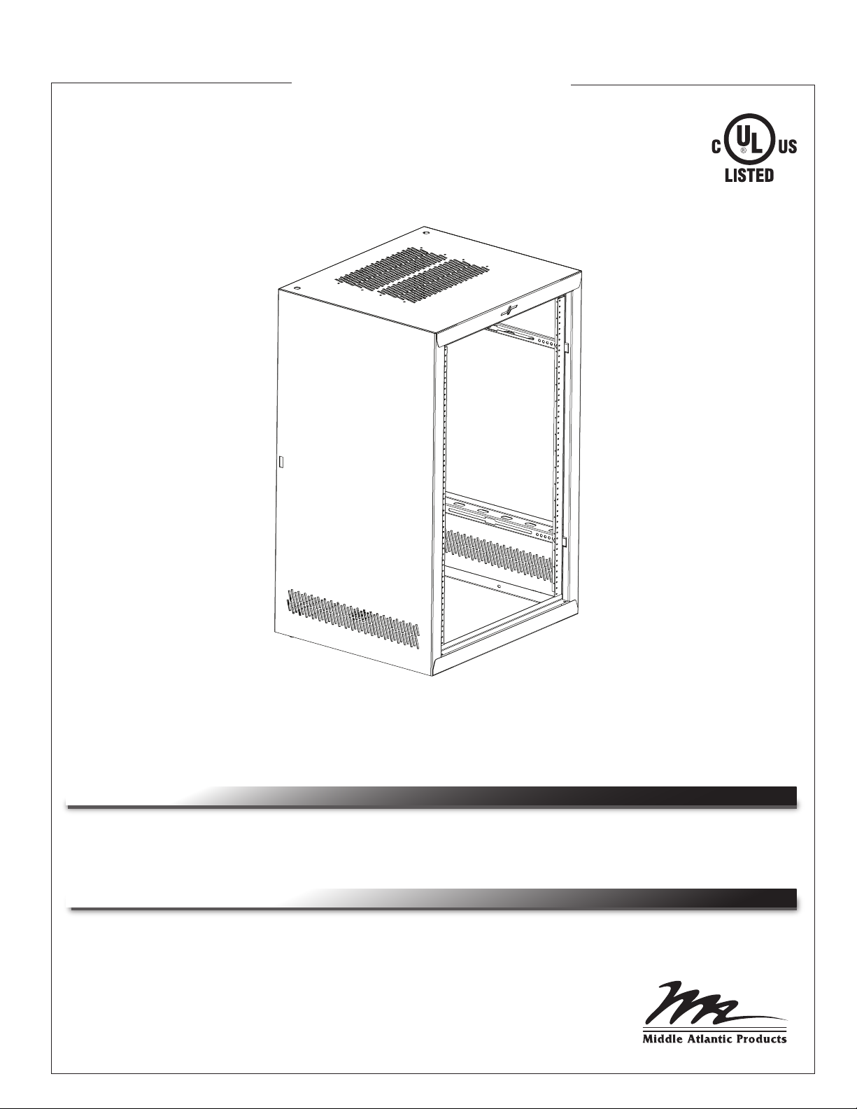
MMR Series
Essex Multi Mount Rack
THANK YOU
Thank you for purchasing the Essex MMR Series Multi Mount Rack.
Please read these instructions thoroughly before installing / assembling this product.
PRODUCT FEATURES
• Multi-purpose design allows for wall mount or floor standing
• Optional quick hang bracket or pivot backpan for easy access to rear of equipment
• Optional active cooling
• Optional locking casters
I-00676 Rev -
Page 2
IMPORTANT SAFETY INSTRUCTIONS
• Read these instructions.
• Keep these instructions.
• Heed all warnings.
• Follow all instructions.
• Clean only with dry cloth.
• Only use attachments/accessories specified by the manufacturer.
WARNING: WARNING INDICATES A POTENTIALLY
!
HAZARDOUS SITUATION WHICH, IF NOT AVOIDED,
COULD RESULT IN DEATH OR SERIOUS INJURY.
CAUTION: CAUTION INDICATES A POTENTIALLY
!
HAZARDOUS SITUATION WHICH, IF NOT AVOIDED,
MAY RESULT IN MINOR OR MODERATE INJURY.
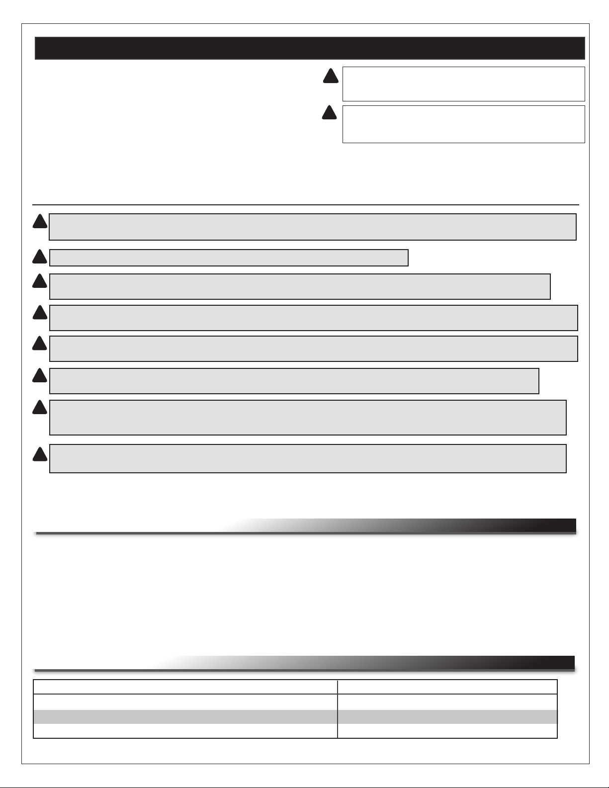
IMPORTANT WARNINGS AND CAUTIONS!
WARNING! Failure to read, understand and follow the following information can result in serious personal injury, damage to the
!
equipment or voiding of the warranty.
CAUTION: All installation and assembly steps must be performed by qualified personnel.
!
CAUTION: Ensure that the wall/floor has a structural load capacity that will support the weight of the cabinet fully loaded with
!
equipment.
CAUTION: Some parts of the enclosure system may not be effectively bonded to the Protective Earth Terminal (PET). If these parts
!
need to be bonded to the PET it should be done in accordance with Article 250 of the National Electrical Code.
CAUTION: Power cord(s), for fans or other accessories, need to be secured to ensure that they are routed away from pinch points
!
and moving parts.
CAUTION: Do not attempt to unload or move the enclosures alone. Make sure to have sufficient amount of personnel and
!
equipment to safely move this product.
CAUTION: The following parts are not effectively bonded to the protective earth terminal: Rackrails, lace bars, Lever Lock™,
!
shelving, baffles, blank panels, and cable management equipment. If any part needs to be bonded to the protective earth terminal
it shall be done in accordance with Article 250 of the National Electrical Code.
CAUTION: To reduce the risk of personal injury and conform to the ul listing these mounting instructions must be
!
followed and proper weight capacity must be observed.
REGULATORY COMPLIANCE
Conforms to applicable UL & CSA standards.
WEIGHT RATINGS
ITEM
WALL MOUNT / FLOOR INSTALLATION
BACKPAN INSTALLATION (OPTIONAL)
HANG BRACKET INSTALLATION (OPTIONAL)
Page 2
DETAILS
250 lbs.
150 lbs. Maximum
150 lbs. Maximum
Maximum
Page 3

CONSIGNES DE SÉCURITÉ IMPORTANTES
• Lisez attentivement ces instructions.
• Conservez ces instructions à portée de la main.
• Prêtez attention à tous les avertissements.
• Suivez toutes les instructions.
• N’utilisez pas cet appareil à proximité de l'eau.
• Utilisez uniquement les cordons et accessoires recommandés par le
fabricant.
AVERTISSEMENT: AVERTISSEMENT INDIQUE UNE
!
SITUATION POTENTIELLEMENT DANGEREUSE
SUSCEPTIBLE, SI ELLE N'EST PAS ÉVITÉE, DE
PROVOQUER LE DÉCÈS OU UNE BLESSURE GRAVE.
ATTENTION: ATTENTION indique une situation
!
potentiellement dangereuse susceptible, si elle n'est pas
évitée, de provoquer une blessure mineure ou modérée.
AVERTISSEMENTS IMPORTANTS ET PRÉCAUTIONS!
AVERTISSEMENT! Ne pas lire, comprendre et suivre les informations suivantes peut entraîner de graves blessures, des
!
dommages à l'équipement ou de la nullité de la garantie.
ATTENTION: Toutes les étapes d'installation et de montage doivent être effectués par du personnel qualifié.
!
ATTENTION: Assurez-vous que le mur / plancher a une capacité de charge de structure qui supporte le poids de l'armoire
!
entièrement chargé avec l'équipement.
ATTENTION: Certaines parties du système d'enceinte ne peuvent pas être efficacement collées à la terre de protection du terminal
!
(PET). Si ces pièces doivent être lié à l'animal, il doit être fait conformément à l'article 250 du Code national de l'électricité.
ATTENTION: Cordon (s), pour les fans ou d'autres accessoires, doivent être garantis afin de s'assurer qu'ils sont acheminés loin
!
des points de pincement et des pièces mobiles.
ATTENTION: N'essayez pas de décharger ou de déplacer les enceintes seules. Assurez-vous d'avoir suffisamment de
!
personnel et de matériel à déplacer en toute sécurité de ce produit.
ATTENTION: Les pièces suivantes ne sont pas effectivement liés à la borne de terre de protection: crémaillères, barres de
!
dentelle, Lever Lock™, étagères, cloisons, panneaux vierges, et des équipements de gestion des câbles. Si une partie doit être
lié à la borne de terre de protection, il doit être fait conformément à l'article 250 du Code national de l'électricité.
ATTENTION: Pour réduire le risque de blessures et sont conformes à la liste UL ces instructions de montage doivent
!
être respectées et la capacité de poids approprié doivent être respectées.
CONFORMITÉ
Le produit répond aux exigences des normes suivantes:
• UL 2416
• CSA C22.2 No.1-04
COTES DE POIDS
ARTICLE
WALL MOUNT / SOL INSTALLATION
PLAQUE PROFILÉE OPTION (OPTION) MURALE / SOL INSTALLATION
HANG SUPPORT INSTALLATION (OPTION)
Page 3
DÉTAILS
250 lbs.
150 lbs. Maximum
150 lbs. Maximum
Maximum
Page 4

TABLE OF CONTENTS
Important Safety Instructions Pages 2-3
Regulatory Compliance Pages 2-3
Weight Ratings Pages 2-3
Tools Required Page 5
Hardware / Items Supplied Page 5
Mounting Dimensions Page 6
Wall Mount Installation Page 7
Optional Hang Bracket Installation Page 8
Optional Hang Bracket Installation (Continued) Page 9
Optional Backpan Installation (Continued) Page 10
Optional Backpan Installation (Continued) Page 11
Grounding and Bonding Page 12
Page 4
Page 5

TOOLS REQUIRED
• #2 Phillips Screwdriver
• Adjustable Wrench
• 1/2” Socket
HARDWARE/ITEMS SUPPLIED
NOTE: Additional hardware may be included which may not be required for your installation.
Bolts
Washers
(Qty 2)
[Hang Bracket / Backpan Installation]
[Hang Bracket / Backpan Installation]
1/2”-13 x 3/4”
(Qty 2)
Security Screw
10-32 x 3/4” with washer
(Qty 1)
[Hang Bracket Installation]
Security Clips
(Qty 2)
[Backpan Installation]
Pivot Pins
(Qty 2)
[Backpan Installation]
Upper Pivot
Bushing
(Qty 1)
[Backpan Installation]
Page 5
Page 6

MOUNTING DIMENSIONS (WALL MOUNT INSTALLATION)
MMR-1820
MMR-1824
MMR-1620
MMR-1624
MMR-1220 MMR-1020
MOUNTING DIMENSIONS (HANG BRACKET INSTALLATION)
HANG-MMR18 HANG-MMR16 HANG-MMR12 HANG-MMR10
MOUNTING DIMENSIONS (BACKPAN INSTALLATION)
PIVOT-MMR-18 PIVOT-MMR-10PIVOT-MMR-12PIVOT-MMR-16
Page 6
Page 7

WALL MOUNT INSTALLATION
NOTE: THE CABINET MUST BE INSTALLED PLUMB AND LEVEL FOR PROPER OPERATION.
NOTE: A sheetrock wall mounted to wood studs on 16” centers is required for installation.
1) Locate studs behind sheetrock wall.
2) Align rear mounting holes in rack with studs. Refer to Mounting Dimensions on Page 6 for mounting
hole locations.
3) Secure rack to studs in wall using all mounting holes (mounting hardware not supplied). (FIGURE A)
NOTE: A minimum of 4” clearance above and below the cabinet is required.
Wood Studs
(16” Apart On Center)
Min. 4”
Clearance
Required
Above And
Below
Rack
Sheetrock
FIGURE A
Page 7
Page 8

OPTIONAL HANG BRACKET INSTALLATION (HANG-MMRXX)
NOTE: THE CABINET MUST BE INSTALLED PLUMB AND LEVEL FOR PROPER OPERATION.
NOTE: A sheetrock wall mounted to wood studs on 16” centers is required for installation.
1) Locate studs behind sheetrock wall.
Hang Bracket Slots
2) Align rear mounting holes in hang bracket with
studs. Refer to Mounting Dimensions on Page 6
for mounting hole locations.
3) Secure bracket to studs in wall using all mounting
holes (mounting hardware not supplied). (FIGURE B)
NOTE: A minimum of 6” clearance above cabinet is
required.
4) Carefully lift rack and place on hang bracket tabs.
(FIGURE C)
NOTE: Hang bracket tabs will align with tab holes in rack.
Sheetrock
Studs
Min. 6”
Clearance
Required
Above And
Below
Rack
Hang Bracket Tabs (2)
FIGURE B
FIGURE C
Hang Bracket
Page 8
Page 9

OPTIONAL HANG BRACKET INSTALLATION (CONTINUED)
5) Secure rack to hang bracket using (2) 1/2”-13 bolts with washers and (1) 10-32 x 3/4” security
screw with washer. (FIGURE D)
Washers
(Qty 2)
FIGURE D
Security Screw
10-32 x 3/4”
with Washer
(Qty 1)
Bolts
1/2”-13 x 3/4”
(Qty 2)
Page 9
Page 10

OPTIONAL BACKPAN INSTALLATION (PIVOT-MMR-XX)
NOTE: THE CABINET MUST BE INSTALLED PLUMB AND LEVEL FOR PROPER OPERATION.
NOTE: A sheetrock wall mounted to wood studs on 16” centers is required for installation.
1) Locate studs behind sheetrock wall.
2) Align rear mounting holes in backpan with studs. Refer to Mounting Dimensions on Page 6 for
mounting hole locations.
3) Secure backpan to studs in wall using all mounting holes (mounting hardware not supplied).
(FIGURE E)
NOTE: A minimum of 4” clearance above and below the cabinet is required.
Wood Studs
(16” Apart On Center)
Min. 4”
Clearance
Required
Above And
Below
Rack
Sheetrock
FIGURE E
Page 10
Page 11

OPTIONAL BACKPAN INSTALLATION (CONTINUED)
4) Insert bushing in upper pivot bushing hole on top of rack. (FIGURE F)
5) Lift rack and place bottom on the edge of backpan. Position
rack so as to engage the lower pivot bushing on backpan.
(FIGURE G)
6) Thread lower pivot pin into lower pivot bushing. Hand
tighten fully and then back out one turn. (FIGURE G)
Lower Pivot
Bushing
Backpan
Pivot
Bushing
FIGURE F
Upper Pivot Pin
Upper Pivot
Bushing
Security Clip
FIGURE G
FIGURE I
Pivot Pin
FIGURE H
Lower Pivot Pin
7) Pivot rack into backpan and align with upper pivot bushing.
(FIGURE H)
8) Thread upper pivot pin into upper pivot bushing. Hand
tighten fully and then back out one turn. (FIGURE H)
9) Install security clips in upper and lower pivot pins to
prevent removal of pivot pins from exterior of enclosure.
(FIGURE I)
Upper and Lower
Security Clips
Page 11
Page 12

GROUNDING AND BONDING
Protective Earth Terminals (PET) are located in the backpan, center section and hang bracket. These terminals are
marked with the symbol Wall rack parts, center section and door, contain or are provided with bonding points for
connection to the backpan / PET. Protective earth and bonding connections shall be in accordance with Article 250 of the
National Electric Code.
1) Attach bonding wire to bonding studs using hardware kit #PET-K-MMR-PH. (FIGURE J)
NOTE: The main protective earth ground needs to be the first terminal placed on the PET and this
terminal needs to be secured on its own with a nut. The bonding wire for the rack can be added to
the PET after securing the nut for the main ground.
Bonding Studs (4) 10-32
Backpan PET
Studs (2) 1/4-20
FIGURE J
Hang Bracket
PET Stud (1)
10-32
Page 12
Page 13

middleatlantic.com/essex
WARRANTY
Middle Atlantic Products (the "Company") warrants the ESSEX MMR SERIES MULTI MOUNT RACK to be free from defects in material or
workmanship for the lifetime of the product.
The Company's entire liability to the purchaser, and the purchaser's (or any other party's) sole and exclusive remedy, under this warranty
shall be limited, at the Company's option, to either (a) return of and refund of the price paid for, or (b) repair or replacement at the
Company's factory of the products purchased, or any part or parts thereof, which the Company has determined to be defective after
inspection thereof at the Company's factory.
This warranty does not cover damage due to acts of God, accident, misuse, abuse or negligence by parties other than the Company, or
any modification or alteration of the products. In addition, this warranty does not cover damage due to improper handling, assembly,
installation or maintenance.
THIS WARRANTY IS IN LIEU OF ALL OTHER WARRANTIES OF ANY KIND, EITHER EXPRESSED OR IMPLIED, INCLUDING, BUT
NOT LIMITED TO, IMPLIED WARRANTIES OF MERCHANTABILITY AND FITNESS FOR A PARTICULAR PURPOSE.
TO THE MAXIMUM EXTENT PERMITTED BY APPLICABLE LAW, IN NO EVENT SHALL THE COMPANY BE LIABLE FOR ANY
SPECIAL, INCIDENTAL, INDIRECT, OR CONSEQUENTIAL DAMAGES WHATSOEVER (INCLUDING, WITHOUT LIMITATION,
DAMAGES FOR LOSS OF BUSINESS PROFITS, BUSINESS INTERRUPTION OR ANY OTHER PECUNIARY LOSS) ARISING OUT OF
THE USE OF THE PRODUCTS PURCHASED, EVEN IF THE COMPANY HAS BEEN ADVISED OF THE POSSIBILITY OF SUCH
DAMAGES. THE COMPANY'S LIABILITY TO THE PURCHASER (OR ANY OTHER PARTY) HEREUNDER, IF ANY, SHALL IN NO
EVENT EXCEED THE PURCHASE PRICE OF THE PRODUCTS PAID TO THE COMPANY.
Corporate Headquarters
Corporate Voice 973-839-1011 - Fax 973-839-1976 / International Voice +1 973-839-8821 - Fax +1 973-839-4982
middleatlantic.com - info@middleatlantic.com
Middle Atlantic Canada
Voice 613-836-2501 - Fax 613-836-2690 / middleatlantic.ca - customerservicecanada@middleatlantic.ca
Factory Distribution
USA: NJ - CA - IL Canada: ON - BC
At Middle Atlantic Products we are always listening. Your comments are welcome.
Middle Atlantic Products is an ISO 9001 and ISO 14001 Registered Company.
 Loading...