

Page 1
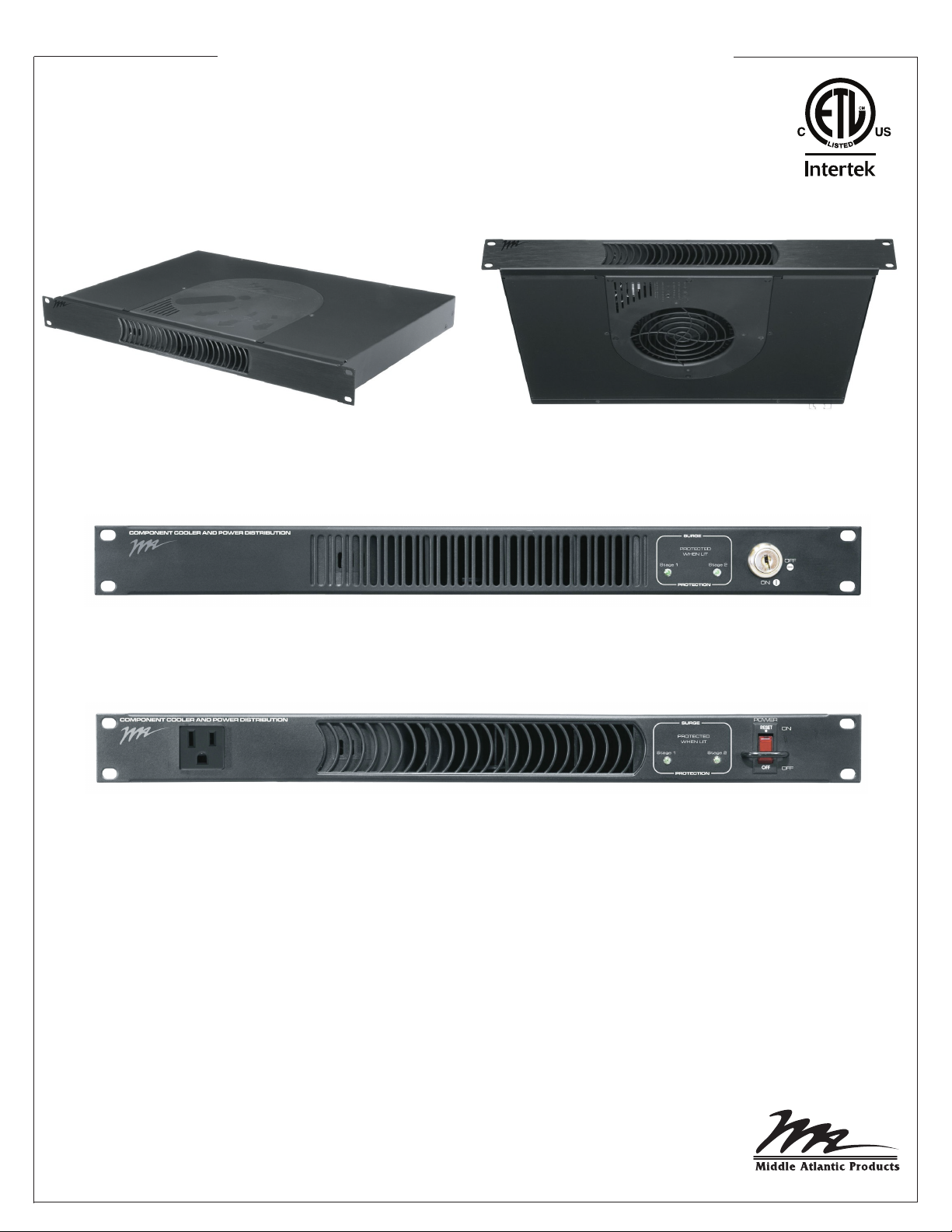
Operation Instructions
PowerCool™ Series
TOP VIEW
BOTTOM VIEW
PDCOOL-1015RA
PDCOOL-1020RK
PDCOOL-1115R
PDCOOL-1120R ALSO AVAILABLE
Thank you for purchasing the PowerCool Series component cooler and power distribution.
Please read these instructions thoroughly before installing/operating this product.
PRODUCT FEATURES
Integrated rackmount power distribution and cooling solution, in one convenient 1RU package:
- Blower exhausts 50CFM while providing high static pressure to maintain airflow.
- Multi-stage surge protection with surge status notification.
- Thermal sensing with proportional blower speed.
I-00572 Rev C
Page 2
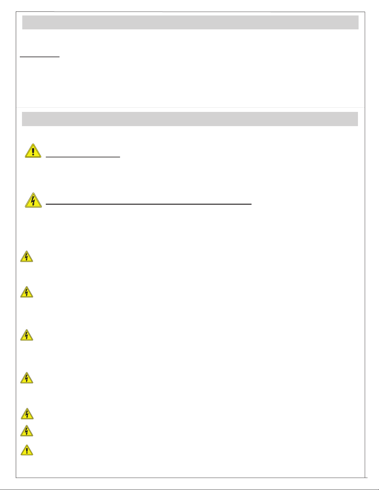
TABLE OF CONTENTS
WARNINGS.........................................................................................................................................2
APPLICATIONS...................................................................................................................................3
FEATURES
PDCOOL-1120R..................................................................................................................................4
PDCOOL-1115R..................................................................................................................................5
PDCOOL-1020RK................................................................................................................................6
PDCOOL-1015RA................................................................................................................................7
WARRANTY.........................................................................................................................................8
WARNINGS
READ AND SAVE THESE INSTRUCTIONS! CONSERVER CES INSTRUCTIONS!
CAUTION/ATTENTION
The exclamation point within an equilateral triangle is intended to alert the user to the presence of important
operating and maintenance (servicing) instructions in the literature accompanying the appliance.
Le point d'exclamation dans un triangle équilatéral est destiné à alerter l'utilisateur de la présence d'importants
instructions d’opération et de maintenance (entretien) dans la documentation accompagnant l'appareil.
DANGER HAZARDOUS VOLTAGE /DANGER HAUTE TENSION
The lightning flash with the arrowhead symbol, within an equilateral triangle is intended to alert the user to the
presence of uninsulated dangerous voltage within the product’s enclosure that may be of sufficient magnitude to
constitute a risk of electric shock to persons.
L'éclair avec le symbole de flèche dans un triangle équilatéral est destiné à alerter l'utilisateur de la présence
d'une tension dangereuse non isolée dans l'enceinte du produit qui peut être d'une ampleur suffisante pour
constituer un risque de choc électrique pour les personnes.
- Contains switched receptacle(s). To reduce risk of shock , disconnect the device from the power
source before servicing any connected equipment
- Contient de(s) receptacle(s) commuté(s). Pour réduire les risques d'électrocution, débran
de la source d'alimentation avant l'entretien de tout équipement connecté
- Do not overload the wall outlet where this device is being connected. Do not overload this device. Ensure the total
load to this device does not exceed that which is listed in the specifications section of this manual
- Ne surchargez pas le réceptacle de mur ou le circuit qui fournit l'énergie à ce appareil. Ne pas surcharger cette
appareil. S'assurer que la charge totale à cet appareil ne dépasse pas celle qui est répertoriée dans la section
des spécifications de ce manuel
- Ensure this device is connected to a properly grounded AC power source. Ensure the device is plugged into a
source providing the required 120V. Do not use a plug adapter that defeats the ground pin of the AC plug
- Assurez-vous cet appareil est
appareil est branché sur une source d’alimentation fournissant les nécessaires 120V. Ne pas utiliser un
adaptateur qui contrecarre la broche de terre de la prise du cordon d’alimentation
- There are no user-serviceable components within this device. Removal of the cover from this device may present
a shock hazard, and void the warranty
- Il n'ya pas de composants réparables par l'utilisateur au sein de cet appareil. Retrait de la couverture de cet
appareil peut présenter un danger d'électrocution et annuler la garantie
- To be used indoors in a dry location only
- Pour être utilisé en intérieur dans un endroit sec seulement
- Do not operate with a damaged cord or plug
- Ne pas faire fonctionner avec un cordon ou une prise endommagée
- Clean only with dry cloth
- Net
toyer avec un chiffon sec seulement
connecté à une source d'alimentation C/A avec mise à la terre. Assurez-vous cet
chez l'appareil
Page 2
Page 3
INSTALLATION NOTES: The MAINS plug or an appliance coupler is used as the disconnect device, the
disconnect device shall remain readily operable.
The socket-outlet shall be installed near the equipment and shall be easily accessible.
APPLICATIONS
- Extracts heat from a specific component within a rack; or the entire rack.
- Powers multiple devices within the rack enclosure.
TO EXTRACT HEAT FROM SINGLE COMPONENT
Install the PDCOOL above the heat producing component. Secure the temperature probe within the
hot air convection chimney, near where the heat is originating. The temperature probe is designed to
measure air temperature and should not be placed directly on the chassis of the unit.
If the equipment has a solid top, you must install a blank panel between the PDCOOL and the
component being cooled to ensure proper thermal management.
If the equipment being cooled is vented, no blank panel is required.
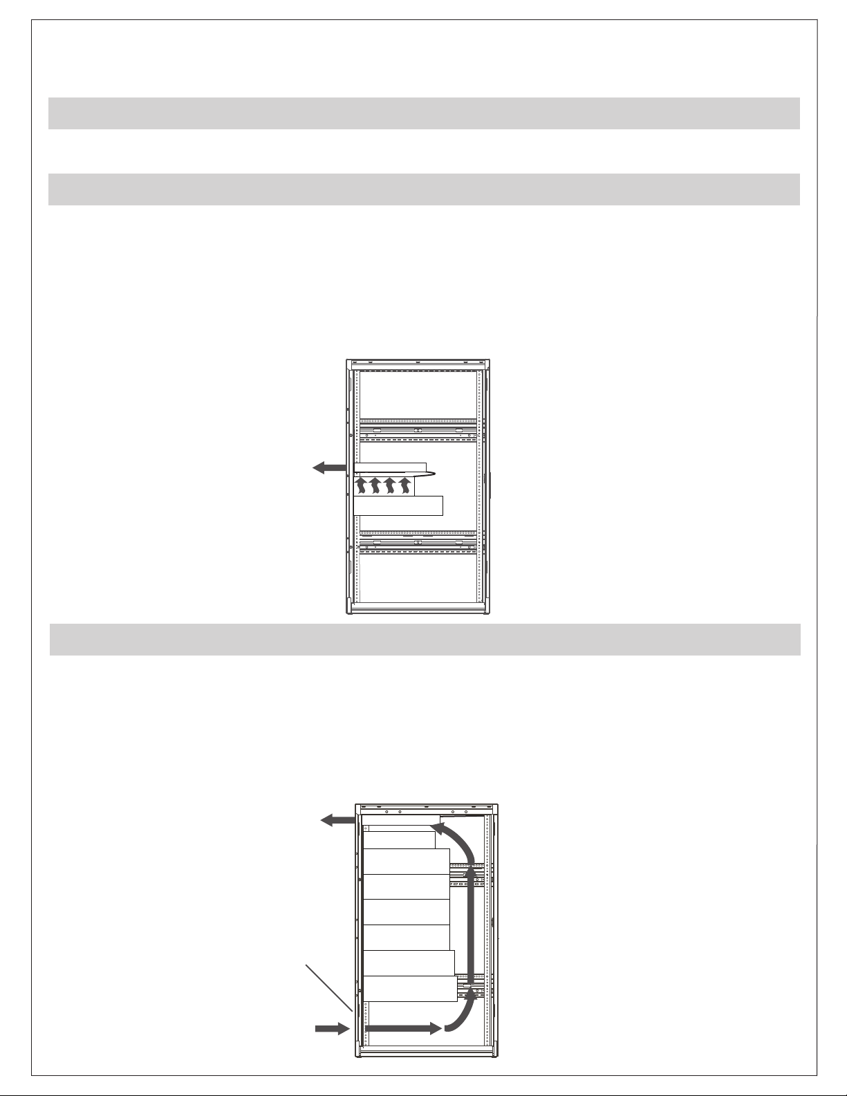
TO EXTRACT HEAT FROM A SMALL RACK
Install the PDCOOL at the top of the rack, and secure the temperature probe at the highest available
location. The PDCOOL is not designed for cooling a large rack.
NOTE: It is important to allow for air flow. If there is not at least one rackspace between the uppermost
component and the PDCOOL, then the PDCOOL should be inverted and installed with the blower
intake facing the top of the rack. Ensure there is a vent panel installed at the bottom of the rack
(or equivalent venting) to allow for air flow intake.
VENT PANEL
Page 3
Page 4

PDCOOL-1120R CONNECTIONS, CONTROLS AND INDICATORS
1
COMPONENT COOLER AND POWER DISTRIBUTION
120 VOLT
16 AMP
60 Hz
FRONT VIEW
1
50CFM BLOWER: This blower will turn on at 87° F (30.5° C) and run proportionately
2
SURGE
PROTECTION
POWER
34
ON
OFF
(speed increases with temperature) from 87° F (30.5° C) to 95° F (35° C). At 95° F and above, the
blower will run at full speed. The blower will stop running at 85° F (29.4° C).
A blue LED will illuminate when the blower is receiving power.
TWO STAGE SURGE SUPPRESSION STATUS INDICATORS:
2
Stage One Indicator Stage Two Indicator Status
On On Full Protection
Off On Stage One Compromised
Off Off Load Unprotected or Power Off
3
POWER SWITCH/20A CIRCUIT BREAKER WITH SWITCH GUARD.
4
NEMA 5-20R POWER OUTLET.
PDCOOL-1120R
65
120V - 60Hz - TOTAL 16A
7
8 9
REAR VIEW
5
C20 IEC POWER CORD INLET: 120V/60Hz power inlet. Plug supplied power cord from AC source
into this inlet.
6 GROUND/BOND STUD.
7 TEN NEMA 5-20R OUTLETS.
8 SURGE STATUS OUTPUT DRY CONTACT: This dry contact will close if both stage 1 and 2 surge is
compromised.
9 TEMPERATURE PROBE CONNECTION: 10 foot temperature probe provided.
Page 4
Page 5

PDCOOL-1115R CONNECTIONS, CONTROLS AND INDICATORS
1
COMPONENT COOLER AND POWER DISTRIBUTION
120 VOLT
12 AMP
60 Hz
FRONT VIEW
1
50CFM BLOWER: This blower will turn on at 87° F (30.5° C) and run proportionately
2
SURGE
PROTECTION
POWER
34
ON
OFF
(speed increases with temperature) from 87° F (30.5° C) to 95° F (35° C). At 95° F and above, the
blower will run at full speed. The blower will stop running at 85° F (29.4° C).
A blue LED will illuminate when the blower is receiving power.
TWO STAGE SURGE SUPPRESSION STATUS INDICATORS:
2
Stage One Indicator Stage Two Indicator Status
On On Full Protection
Off On Stage One Compromised
Off Off Load Unprotected or Power Off
3
POWER SWITCH/15A CIRCUIT BREAKER WITH SWITCH GUARD.
4
NEMA 5-15R POWER OUTLET.
PDCOOL-1115R
65
120V - 60Hz - TOTAL 12A
7
8 9
Tem p
Surge
Probe
Status
Closed if
Compromised
REAR VIEW
C14 IEC POWER CORD INLET: 120V/60Hz power inlet. Plug supplied power cord from AC source
5
into this inlet.
6
GROUND/BOND STUD.
7 TEN NEMA 5-15R OUTLETS.
8 SURGE STATUS OUTPUT DRY CONTACT: This dry contact will close if both stage 1 and 2 surge is
compromised.
9 TEMPERATURE PROBE CONNECTION: 10 foot temperature probe provided.
Page 5
Page 6

PDCOOL-1020RK CONNECTIONS, CONTROLS AND INDICATORS
1
COMPONENT COOLER AND POWER DISTRIBUTION
2
SURGE
PROTECTION
3
OFF
ON
FRONT VIEW
1
50CFM BLOWER: This blower will turn on at 87° F (30.5° C) and run proportionately
(speed increases with temperature) from 87° F (30.5° C) to 95° F (35° C). At 95° F and above, the
blower will run at full speed. The blower will stop running at 85° F (29.4° C).
A blue LED will illuminate when the blower is receiving power.
2
TWO STAGE SURGE SUPPRESSION STATUS INDICATORS:
Stage One Indicator Stage Two Indicator Status
On On Full Protection
Off On Stage One Compromised
Off Off Load Unprotected or Power Off
3
KEYED POWER SWITCH: Using provided key, you can turn the power on/off and remove the key
for security.
5
PDCOOL-1020RK
C20 IEC POWER CORD INLET: 120V/60Hz power inlet. Plug supplied power cord from AC source
5
6
Reset
10
7
120V - 60Hz - TOTAL 16A
REAR VIEW
8 9
into this inlet.
20 AMP CIRCUIT BREAKER: Provides protection for both front and rear outlets.
6
7 TEN NEMA 5-20R OUTLETS.
8 SURGE STATUS OUTPUT DRY CONTACT: This dry contact will close if both stage 1 and 2 surge is
compromised.
9 TEMPERATURE PROBE CONNECTION: 10 foot temperature probe provided.
10 GROUND/BOND STUD.
Page 6
Page 7

PDCOOL-1015RA CONNECTIONS, CONTROLS AND INDICATORS
1
FRONT VIEW
1
50CFM BLOWER: This blower will turn on at 87° F (30.5° C) and run proportionately
(speed increases with temperature) from 87° F (30.5° C) to 95° F (35° C). At 95° F and above, the
blower will run at full speed. The blower will stop running at 85° F (29.4° C).
A blue LED will illuminate when the blower is receiving power.
2
PDCOOL-1015RA
C14 IEC POWER CORD INLET: 120V/60Hz power inlet. Plug supplied power cord from AC source
2
3
Reset
7
4
120V - 60Hz - TOTAL 12A
REAR VIEW
5 6
into this inlet.
15 AMP CIRCUIT BREAKER: Provides protection for both front and rear outlets.
3
4 TEN NEMA 5-15R OUTLETS.
5 SURGE STATUS OUTPUT DRY CONTACT: This dry contact will close if both stage 1 and 2 surge is
compromised.
6 TEMPERATURE PROBE CONNECTION: 10 foot temperature probe provided.
7 GROUND/BOND STUD.
Page 7
Page 8

WARRANTY
Middle Atlantic Products, Inc. (the "Company") warrants the PowerCool Series to be free from defects in material or workmanship under normal use and
conditions for a period of (3) three years from the date of shipment by the company.
The Company's entire liability to the purchaser, and the purchaser's (or any other party's) sole and exclusive remedy, under this warranty shall be
limited, at the Company's option, to either (a) return of and refund of the price paid for, or (b) repair or replacement at the Company's factory of the
products purchased, or any part or parts thereof, which the Company has determined to be defective after inspection thereof at the Company's factory.
This warranty does not cover damage due to acts of God,accident, misuse, abuse or negligence by parties other than the Company, or any
modification or alteration of the products. In addition, this warranty does not cover damage due to improper handling, assembly, installation or
maintenance.
THIS WARRANTY IS IN LIEU OF ALL OTHER WARRANTIES OF ANY KIND, EITHER EXPRESSED OR IMPLIED, INCLUDING, BUT NOT LIMITED TO,
IMPLIED WARRANTIES OF MERCHANTABILITY AND FITNESS FOR A PARTICULAR PURPOSE.
TO THE MAXIMUM EXTENT PERMITTED BY APPLICABLE LAW, IN NO EVENT SHALL THE COMPANY BE LIABLE FOR ANY SPECIAL, INCIDENTAL,
INDIRECT, OR CONSEQUENTIAL DAMAGES WHATSOEVER (INCLUDING, WITHOUT LIMITATION, DAMAGES FOR LOSS OF BUSINESS PROFITS,
BUSINESS INTERRUPTION OR ANY OTHER PECUNIARY LOSS) ARISING OUT OF THE USE OF THE PRODUCTS PURCHASED, EVEN IF THE
COMPANY HAS BEEN ADVISED OF THE POSSIBILITY OF SUCH DAMAGES. THE COMPANY'S LIABILITY TO THE PURCHASER (OR ANY OTHER
PARTY) HEREUNDER, IF ANY, SHALL IN NO EVENT EXCEED THE PURCHASE PRICE OF THE PRODUCTS PAID TO THE COMPANY.
Corporate Headquarters
Corporate Voice 973-839-1011 - Fax 973-839-1976 / International Voice +1 973-839-8821 - Fax +1 973-839-4982
middleatlantic.com - info@middleatlantic.com
Middle Atlantic Canada
Voice 613-836-2501 - Fax 613-836-2690 / middleatlantic.ca - customerservicecanada@middleatlantic.ca
Factory Distribution
USA: NJ - CA - IL Canada: ON - BC
At Middle Atlantic Products we are always listening. Your comments are welcome.
Page 8
 Loading...