

Page 1

Instruction Sheet
L2 SERIES
Lectern
NOTE: L2 lectern
shown with a
flip-up side shelf
configuration.
THANK YOU
Thank you for purchasing the L2 Series lectern. Please read these instructions thoroughly before
installing or assembling this product.
PRODUCT FEATURES
• The only budget-friendly lectern solution that delivers support and security for AV systems,
complete with a patent-pending rack, power, thermal and cable management, and connectivity
• The 12RU removable rack boasts a tool-less experience with easy access to rear connections or
removal for simple servicing, yet locks in place for transportation
• Flip-up side shelf for extra surface space on certain models
I-00824 Rev -
Page 2

IMPORTANT SAFETY INSTRUCTIONS
• Read these instructions.
• Keep these instructions.
DANGER HAZARDOUS VOLTAGE: The lightning flash with the arrowhead symbol, within an equilateral triangle is intended to alert the user to the
presence of uninsulated dangerous voltage within the product’s enclosure that may be of sufficient magnitude to constitute a risk of electric shock to
persons.
WARNING: A warning alerts you to a situation that could result in serious personal injury or death.
CAUTION: A caution alerts you to a situation that may result in minor personal injury or damage to the product and/or property.
NOTE: A note is used to highlight procedures pertaining to the installation, operation, or maintenance of the product.
WARNING: Failure to read, understand and follow the following information can result in serious personal injury, damage to the
equipment or voiding of the warranty. It is the responsibility of the Installer/User to ensure that this product is loaded according to
specifications.
WARNING: Exceeding the weight ratings on page 4 can result in serious injury or damage to the equipment. It is the responsibility of
the Installer/User to ensure the components installed do not surpass the weight ratings as an unstable condition can occur which may
cause possible injury or damage.
CAUTION: If there is visible damage on the product, it must not be installed.
CAUTION: Safety measures must be practiced at all times during the assembly of this product. Use proper safety equipment and
tools for the assembly procedure to prevent personal injury.
• Heed all warnings.
• Follow all instructions.
• Clean only with dry cloth.
• Only use attachments/accessories specified by the manufacturer.
CAUTION: Note that during construction, there must be no possibility of personal injury, for example the squeezing of fingers or
arms.
CAUTION: For loading, always put heavier items at the bottom of the bays, not near the top, in order to help prevent the possibility
of the furnishing tipping over.
CAUTION: The appliance is not intended for use by young children or infirm persons without supervision.
Safety Instructions: Rack Mount
Elevated Operating Ambient: If installed in a closed or multi-unit rack assembly, the operating ambient temperature of the rack
environment may be greater than room ambient. Therefore, consideration should be given to installing the equipment in an environment
compatible with the maximum ambient temperature (Tma) specified by the manufacturer.
Reduced Air Flow: Installation of the equipment in a rack should be such that the amount of air flow required for safe operation of the
equipment is not compromised.
Mechanical Loading: Mounting of the equipment in the rack should be such that a hazardous condition is not achieved due to uneven
mechanical loading.
Circuit Overloading: Consideration should be given to the connection of the equipment to the supply circuit and the effect that
overloading of the circuit might have on overcurrent protection and supply wiring. Appropriate consideration of equipment nameplate
ratings should be used when addressing this concern.
Reliable Earthing: Reliable earthing of rack-mounting equipment should be maintained. Particular attention should be given to supply
connections other than direct connections to the branch circuit (e.g. use of power strips).
Disconnect Device (Pluggable Equipment): The socket-outlet shall be installed near the equipment and shall be easily accessible.
Page 2
Page 3
INSTRUCTIONS IMPORTANTES SUR LA SÉCURITÉ
• Lire ces instructions.
• Conservez ces instructions.
DANGER TENSION DANGEREUSE: Le symbole de la pointe de flèche, dans un triangle équilatéral, est destiné à alerter l'utilisateur sur la
présence de tension dangereuse non isolée dans l'enceinte du produit qui peut être d'une ampleur suffisante pour constituer un risque d'électrocution.
AVERTISSEMENT: Un avertissement vous avertit d'une situation pouvant entraîner des blessures graves ou la mort.
ATTENTION: Une attention vous avertit d'une situation pouvant entraîner des blessures mineures ou des dommages au produit et/ou à la
REMARQUE: Une remarque est utilisée pour mettre en évidence les procédures relatives à l'installation, au fonctionnement ou à l'entretien du
produit.
AVERTISSEMENT: Refus de lire, comprendre et suivre la renseignements suivants peut traduire par de graves blessures, des
dommages à l'équipement ou invalider la garantie. Il est la responsabilité de l'installateur/utilisateur de s'assurer que ce produit
est chargé conformément aux spécifications.
AVERTISSEMENT: Le dépassement des notes de poids à la page 4 peut entraîner des blessures graves ou des dommages à
l'équipement. C'est l'responsabilité de l'installateur/utilisateur de s'assurer que les composants installé ne dépassent pas les notes
de poids comme un instable condition peut se produire qui peut causer des blessures ou dommages.
ATTENTION: S'il ya des dommages visibles sur le produit, il ne doit pas être installé.
ATTENTION: Des mesures de sécurité doivent être mises en œuvre en tout temps lors de l'assemblage de ce produit. Utiliser un
équipement et des outils de sécurité appropriés pour la procédures de afin d'éviter les blessures.
• Respectez tous les avertissements.
• Suivez toutes les instructions.
• Nettoyer uniquement avec un chiffon sec.
• N'utilisez que des accessoires spécifiés par le fabricant.
ATTENTION: Notez que pendant la construction, il ne doit pas y avoir de risque de blessure, comme par exemple le écraser des
doigts ou des bras.
ATTENTION: Pour le chargement, placez toujours des articles plus lourds au bas des baies, pas près du sommet, afin d'éviter la
possibilité de basculement de l'ameublement.
ATTENTION: L'appareil n'est pas destiné à être utilisé par des enfants en bas âge ou des personnes infirmes sans surveillance.
Consignes de sécurité: montage en rack
Température de fonctionnement élevée: Si installé dans un rack fermé ou à unités multiples , la température ambiante de fonctionne-
ment de l'environnement du rack peut être supérieure à ambiante de la pièce. Par conséquent, il faudrait envisager d'installer l'équipement dans un environnement compatible avec la température ambiante maximale (Tma) spécifiée par le constructeur.
Réduction Air accréditives: Installation de l'équipement dans un rack doit être telle que la quantité de flux d'air nécessaire au bon
fonctionnement de l'équipement ne soit pas compromise.
Chargement mécanique: Le montage de l'équipement dans le rack doit être telle qu'une condition dangereuse ne lié à un chargement
mécanique irrégulier.
Surcharge des circuits: Il faudrait envisager à la connexion de l'équipement au circuit d'alimentation et l' effet que la surcharge du
circuit pourrait avoir sur la protection contre les surintensités et le câblage d'alimentation. Examen approprié des équipements évaluations de la plaque signalétique doit être utilisée pour traiter de cette préoccupation.
Mise à la terre fiable: Fiable mise à la terre de l'équipement de montage en rack doit être maintenue. Une attention particulière devrait
être accordée aux connexions d'alimentation autres que les connexions directes vers le circuit de dérivation (par exemple de l'utilisation
de bandes de puissance).
Appareil Disconnect (Équipement Pluggable): La prise de courant doit être installée à proximité du matériel et doit être facilement
accessible.
Page 3
Page 4
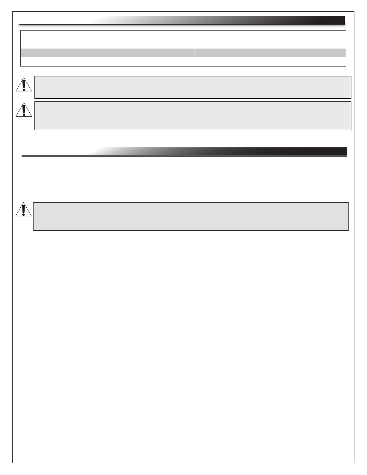
WEIGHT RATINGS
Model Number Weight Rating
Rack Inside L2 Lectern
Flip-Up Side Shelf
Lectern, Rack, and Flip-Up Side Shelf
WARNING: This product is intended for use only with the products and maximum weights indicated. Use with other products or
products heavier than the maximum weights indicated may result in instability causing possible injury. Total equipment weight must
not exceed 150 lbs. (68.04 kg).
AVERTISSEMENT: Cette produit est conçu pour être utilisé uniquement avec les produits et les poids maximum indiqué. uniquement avec les produits et les poids maximaux indiqués. En cas d'utilisation avec d'autres produits ou des produits plus lourds que
le poids maximal indiqué, le chariot peut devenir instable et causer des blessures. Le poids total de l'équipement ne doit pas
dépasser 68.04 kg (150 lbs).
75 lbs. Maximum Total Rated Load
20 lbs. Maximum Total Rated Load
150 lbs. Maximum Total Rated Load
REQUIRED TOOLS
• Power Driver
• 1/4” Drill Bit
• Power Driver With 6“ Long Phillips Bit or 6” Long #2 Phillips Screwdriver
• Hammer
WARNING: Use tools with caution and follow all necessary safety protocols.
AVERTISSEMENT: Utiliser des outils avec prudence et suivre tous les protocoles de sécurité
nécessaires.
Page 4
Page 5
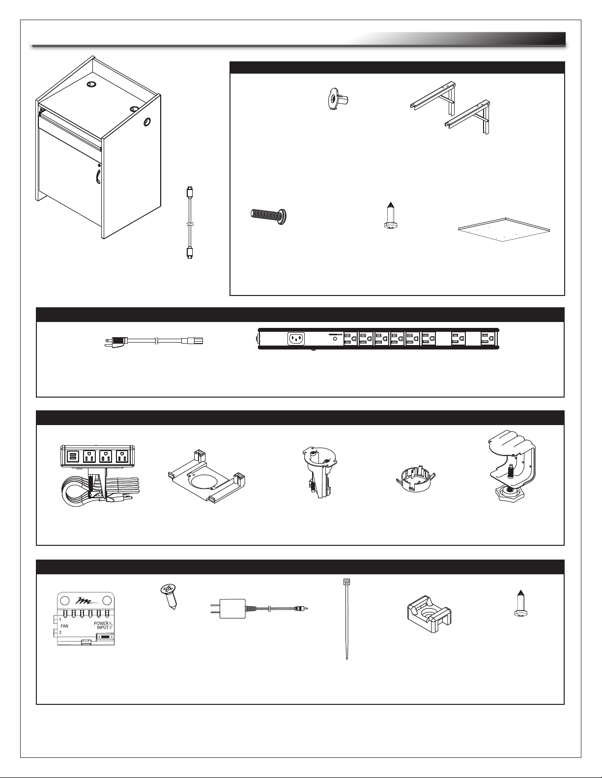
SUPPLIED COMPONENTS AND HARDWARE
FLIP-UP SIDE SHELF (IF ORDERED)
(6x)
8-32 x 1”
T-nuts
B
Side Shelf
Brackets
C
L2 Lectern
HDMI Cable
(6’ Length)
A
POWER STRIP
Power Cable
(10’ Length, Pre-Installed)
G
DESKTOP POWER CENTER (WSC320-S)
Power Unit
J
Mounting Plate
K
(6x)
8-32 x 1 1/4”
Machine
Screw
D
Hole Mount
L
(6x)
#8 Wood
Screw
E
Power Strip
(Pre-Installed)
H
Bushing
M
Side Shelf
F
Edge Mount
Clamp
(NOT USED)
FAN CONTROLLER
Fan Controller
N
NOTE: Additional hardware is included that may not be required for your installation.
(2x)
#6 x 1/2”
Wood
Screw
P
Fan Controller
Power Supply
R
Page 5
(12x)
Wire Tie
S
(6x)
Tie Saddle
T
(6x)
#10 x 5/8”
Tie Saddle
Screw
U
Page 6
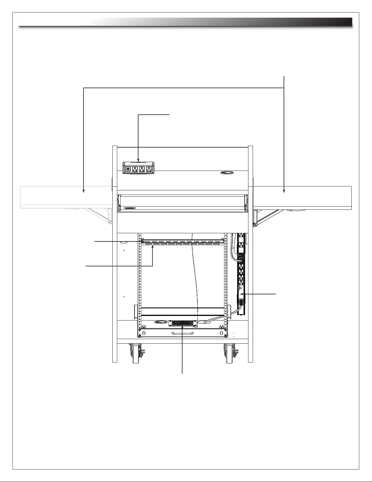
PRODUCT FEATURES (CONTINUED)
Offset Lacer Bar
on Back of Lectern
(May be installed on either side of lectern.)
Flip-Up Side Shelf
Desktop Power Center
(WSC320-S, may be installed in either top grommet hole.)
Lacer Bar
on Back of Rack
NOTE: Door removed for clarity.
Power Strip
Fan With Thermostatic Control
Page 6
Page 7

REMOVING THE RACK FROM THE GUIDE BRACKETS
1. Remove (2x) thumb screws. (FIGURE A)
2. Use handle on front of lower rack to pull the framework out of the lectern and off the guide brackets.
3. Reverse the procedure to re-install the rack.
NOTE: Carefully review all other topics in these instructions before loading equipment in the rack,
performing cable management, and re-installing the rack inside the lectern.
Guide
Brackets
Handle
Thumb
Screws
RELOCATING THE RACK
The rack comes pre-assembled
with the guide brackets in the center
position; however, they may be
moved to the right (facing) position, if
desired.
1. Use power driver or screwdriver to
remove the (4x) #10 x 5/8” screws
on the guide brackets to remove
them from the bottom of the lectern.
(FIGURE B)
2. Shift the guide brackets to the other
pre-drilled holes.
3. Use the screws to attach each
guide bracket to the bottom of the
lectern.
FIGURE A
FIGURE B
NOTE: Door removed for clarity.
(4x)
#10 x 5/8”
Screws
Pre-Drilled
Holes
for Right
Alignment
Page 7
Page 8

INSTALLING THE FLIP-UP SIDE SHELF
Use the following topic if your lectern configuration includes a flip-up side shelf.
1. Locate pilot mounting holes on the inside of the lectern on the side you wish to install the shelf.
(FIGURE C)
NOTE: The figure shows a right panel shelf installation, but the procedure is typical for either side.
2. Use power driver and 1/4” bit to enlarge
and drill through the 6 mounting holes
from the inside surface of the side
C
panel.
3. Make sure both side shelf brackets (C)
are in the open position as shown.
NOTE: Press long end of the bracket
underside to adjust position.
4. Use (6x) 8-32 x 1 1/4” machine screws
(D, 3 per bracket) and (6x) T-nuts (B)
to attach brackets to the side panel as
shown. Do not fully tighten screws at
this point. (FIGURE C)
B
Mounting
Holes
D
5. Use (6x) #8 wood screws (E, 3 per
bracket) to attach the side shelf (F) to
FIGURE C
the brackets. Do not fully tighten screws
at this point. (FIGURE D)
6. Press the long ends of the brackets to
move the side shelf into the up
and down positions and make fine
adjustments to the screws as necessary.
7. Tighten all screws. Do not overtighten.
NOTE: Make sure T-nuts (B) are fully
seated on the inside of the side panel
when tightening the machine screws (D)
at this point.
F
E
FIGURE D
Page 8
Page 9

CONNECTING THE POWER STRIP TO A POWER SOURCE
The lectern comes with a power strip pre-installed in the right (facing) position; however, you must
connect the power cord to your desired power source.
1. The power cable (G) should already be plugged into the receptacle on the power strip (H) and secured
in place with the power cable retainer. (FIGURE E)
NOTE: Different IEC cables may be used; however, the length must be a minimum of 5ft. (1.5M) and a
maximum of 15ft. (4.5M).
G
Power Cable
Retainer
H
FIGURE E
2. Run the power cable (H) through one of the grommet holes on the bottom of the lectern and into your
desired receptacle. (FIGURE F)
NOTE: Right
side of lectern
removed for
clarity.
H
FIGURE F
Page 9
Page 10

RELOCATING THE POWER STRIP
The lectern comes with a power strip pre-installed in the right (facing) position; however, it may be moved
to the left position, if desired.
1. Remove the power cable (G) from the power strip (H).
2. Pull the power strip (H) from the power mounting clips. (FIGURE G)
NOTE: Different IEC cables may be used; however, the length must be a minimum of 5ft. (1.5M) and a
maximum of 15ft. (4.5M).
TIP: To remove the power strip
(H) from the power mounting
Screwdriver Tip
clips, wedge a flat head screwdriver between the side of the
power strip and clip, and gently
H
FIGURE G
pry them from each other as
shown. (FIGURE G)
Power
Mounting
Clip
3. Use power driver to remove wood screw on each power mounting clip to remove them from the back
of the lectern.
4. Locate pilot mounting holes on the left side (inside) of the lectern. (FIGURE H)
5. Reverse the steps to install the power strip on the left side.
Pilot mounting
holes on left side
of lectern.
NOTE: Right
side of lectern
removed for
clarity.
FIGURE H
Page 10
Page 11

INSTALLING THE DESKTOP POWER CENTER (WSC320-S)
1. Decide which lectern top grommet hole you wish to
install the desktop power center in and remove
that grommet from the lectern. (FIGURE J)
2. Press tabs on rear of power unit (J) to
remove it from the mounting plate (K).
J
(FIGURE K)
Lectern Top
Grommets
FIGURE J
Tabs
K
FIGURE K
3. Insert hole mount (L) through mounting plate (K),
bushing (M), and into selected top grommet hole.
(FIGURE L)
L
K
M
Page 11
FIGURE L
Page 12

INSTALLING THE DESKTOP POWER CENTER (WSC320-S, CONTINUED)
4. Tighten (2x) screws on the hole mount (L) to secure the assembly to the top grommet hole as shown.
(FIGURE M)
Tighten (2x) Screws
L
K
FIGURE M
5. Run the power unit’s (J) power cable through the top grommet hole and connect it to the power strip (H).
Hook the front slots on the power unit (J) to the clips on the mounting plate (K) as shown. (FIGURE N)
NOTE: Other cables may be run up and/or down the opening during this step. The recessed opening on
the back of the power unit (J) accommodates additional cables, such as the included 6’ HDMI cable (A).
J
Recessed
Opening
Front
Slot
A
K
Clip
FIGURE N
Page 12
Page 13

INSTALLING THE DESKTOP POWER CENTER (WSC320-S, CONTINUED)
6. Insert 2 tabs on the back of the power unit (J) into the slots on the back of the mounting plate (K) until
it clicks into place. (FIGURE P)
Tabs on Back of
Power Unit
Slots on Back of
Mounting Plate
FIGURE P
WIRING THE PRE-INSTALLED FAN
1. Use the jumper on the inline fan controller (N) for
N
Jumper
the following functions:
• Jumper on two center pins (pre-installed location)
turns the fan on at 87º and off at 85º. (FIGURE R)
• Jumper on two left pins, fan will remain off.
• Jumper on two right pins, fan will remain on.
Side View of Inline Fan Controller
FIGURE R
2. Use (2x) wood screws (P) to mount the inline fan controller (N) into the pre-drilled holes on the inside
back of the lectern. (FIGURE S)
NOTE: Door and right side of
lectern removed for clarity.
P
FIGURE S
N
Pre-Drilled
Holes
Page 13
Page 14

WIRING THE PRE-INSTALLED FAN (CONTINUED)
3. Run the cable from the fan to the inline fan controller (N). (Inputs 1 and 2 are interchangeable.)
(FIGURE T)
4. Connect the fan controller power supply (R) to the input on inline fan controller (N).
5. Connect power supply to power strip (H).
NOTE: Wire ties (S), tie saddles (T), and tie saddle screws (U) are provided for cable management.
N
Jumper Pins
Cable
From Fan
FIGURE T
ADJUSTING THE FRONT DOOR (IF NECESSARY)
• If necessary, use a screwdriver to adjust the door hinges as shown. (FIGURE U)
R
FIGURE U
Side Adjustment Depth AdjustmentHeight Adjustment
Page 14
Page 15

RELOCATING THE LACER BAR INSIDE THE BACK OF THE LECTERN
If desired, you may relocate the lacer bar that is pre-installed inside the back of the lectern into any of the
pre-drilled screw locations. (FIGURE V)
NOTE: Leaving the lacer bar in the pre-installed top position is best for forming a proper service loop as
shown in the next topic.
1. Use power driver or screwdriver to remove (2x) #10 x 5/8” screws from the lacer bar.
2. Find the pre-drilled holes on the inside of the lectern in the position you wish to relocate the
lacer bar. (FIGURE V)
3. Re-attach the lacer bar using the screws.
(2x)
#10 x 5/8”
Screws
LOCATION 1
LOCATION 2
LOCATION 3
NOTE: Back of lectern isolated
for clarity.
FIGURE V
Page 15
Page 16

CABLE MANAGEMENT
This topic shows you how to create a proper service loop when running cables to equipment installed in
the rack inside your lectern.
1. Load your equipment into the rack and form a service loop by using wire ties (S) to attach the cables
to the lacer bars on the back of the rack and lectern as shown. (FIGURE W)
NOTE: The length of the service loop should be a minimum of 2’ for proper clearance when removing the
rack from the lectern and servicing equipment.
2. Run the equipment cables through one of the grommet holes on the bottom of the lectern and into
your desired receptacle.
3. Re-install the rack on the guide brackets inside the lectern. For more information, see “Removing the
Rack From the Guide Brackets” on page 7.
2’ Minimum Service
Loop Length
S
Run Cables
to Desired
Connections
Inside
of
Lectern
NOTE: Side and back of lectern
removed for clarity.
FIGURE W
Page 16
Page 17

WARRANTY
For warranty information, refer to http://www.middleatlantic.com/company/about-us.aspx#warranty
Corporate Headquarters
Corporate Voice: 973-839-1011 - Fax: 973-839-1976 / International Voice: +1 973-839-8821 Fax: +1 973-839-4982
www.middleatlantic.com - info@middleatlantic.com
Middle Atlantic Canada
Voice: 613-836-2501 - Fax: 613-836-2690 / ca.middleatlantic.com customerservicecanada@middleatlantic.ca
Factory Distribution
USA: NJ - CA - IL Canada: ON - BC
At Middle Atlantic Products we are always listening. Your comments are welcome.
Middle Atlantic Products is an ISO 9001 and ISO 14001 Registered Company.
Page 17
Page 18

 Loading...