

Page 1
Instruction Sheet
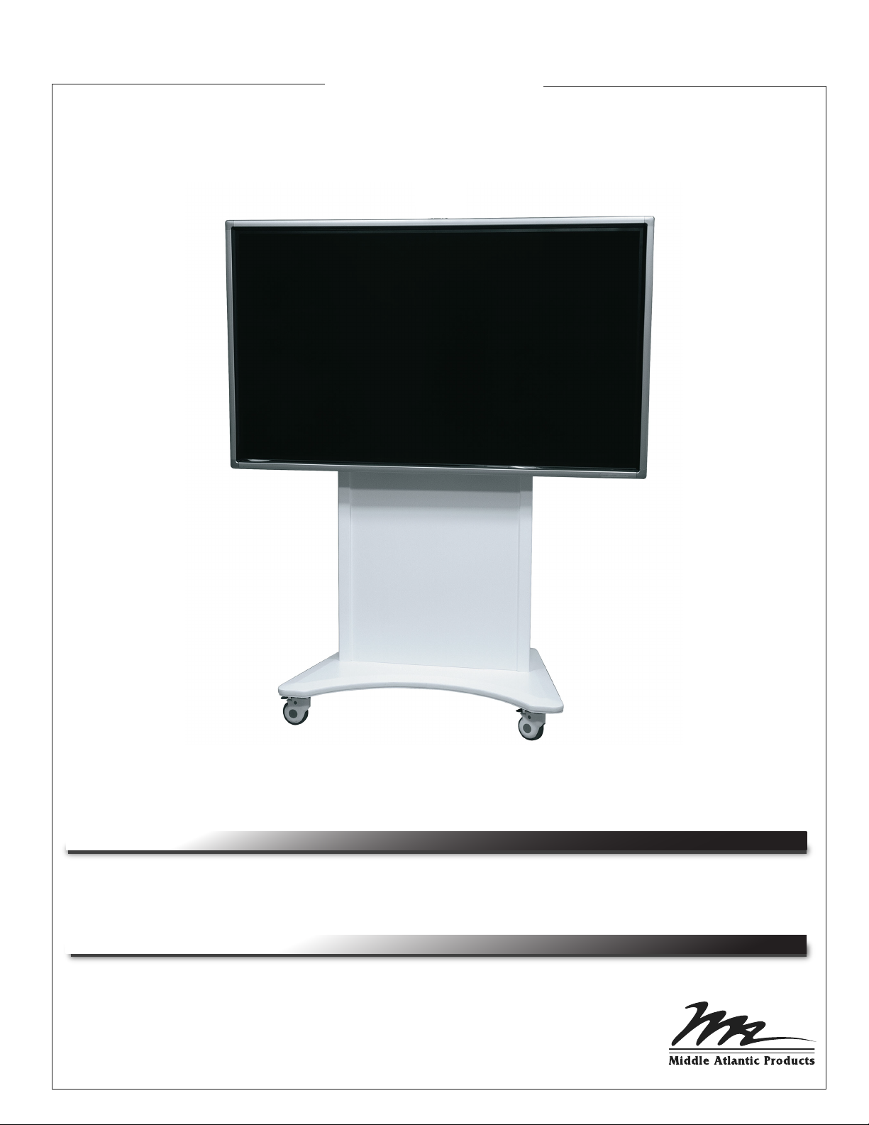
FlexView
FVS Series
THANK YOU
Thank you for purchasing the FlexView FVS Series. Please read these instructions thoroughly
before installing this product.
PRODUCT FEATURES
• Middle Atlantic PD-815SC (8) outlet, 15 amp power strip with surge and circuit breaker
• Simple display mounting with choice of monitor height
• Lever Lock™ for easy mounting of Codecs and smaller components
• Adjustable cable management included
I-00668 Rev -
Page 2
IMPORTANT SAFETY INSTRUCTIONS
WARNING/CAUTION! The exclamation point within an
!
equilateral triangle is intended to alert the user to the
presence of important operating and maintenance
(servicing) instructions in the literature accompanying the
appliance
!
AVERTISSEMENT/ATTENTION! Le point d'exclamation
dans un triangle équilatéral est destiné à alerter l'utilisateur
de la présence d'importants instructions d’opération et de
maintenance (entretien) dans la documentation
accompagnant l'appareil.
WARNING! Failure to read, understand and follow the
!
following information can result in serious personal injury,
damage to the equipment or voiding of the warranty. It is
the responsibility of the Installer/User to ensure
that this product is loaded according to specifications.
CAUTION! To avoid an unstable condition, place heavier
!
components at the bottom of the cabinet. When more than
one component is placed in the cabinet, begin at the
bottom of the cabinet and place equipment at the lowest
available point, evenly distribute weight (vertically) within
the cabinet.
ATTENTION! Pour éviter une condition instable, placer
!
des composants plus lourds dans le bas de l'armoire.
Lorsque plus d'un composant sera placé dans l'armoire,
commencez en bas de l'armoire, placent l'équipement sur
le point le plus bas disponible, distribuant uniformément le
poids (verticalement) dans l l'armoire.
WARNING! For use with televisions weighing 190lbs
!
(86 Kg) or less. Use with heavier televisions may
result in instability causing tip over resulting in death
or serious injury.
AVERTISSEMENT! Refus de lire, comprendre et suivre
!
la renseignements suivants peut traduire par de graves
blessures, des dommages à l'équipement ou invalider la
garantie. Il est la responsabilité de l'installateur / utilisateur
de s'assurer que ce produit est chargé conformément aux
spécifications.
WARNING! The weight ratings of this product can be
!
found on the product. Exceeding these weight ratings can
result in serious injury or damage to the equipment. It is the
responsibility of the Installer/User to ensure the components
installed do not surpass the weight ratings as an unstable
condition can occur which may cause possible injury or
damage.
AVERTISSEMENT! Les caractéristiques de poids de ce
!
produit peuvent être trouvées sur le produit. Le
dépassement de ces caractéristiques de poids peut
entraîner des blessures graves ou des dommages
à l'équipement. C'est l'responsabilité de l'installateur /
utilisateur de s'assurer que les composants installé ne
dépassent pas les notes de poids comme un instable
condition peut se produire qui peut causer des blessures
ou dommages.
WARNING! Relocating audio and/or video equipment to furniture
!
not specifically designed to support audio and/or
video equipment may result in death or serious injury due to
the furnishing collapsing or over turning onto a child.
AVERTISSEMENT - Pour utilisation avec des téléviseurs
!
pesant 190 lbs (86.2 kg) ou moins. Utilisation avec des
téléviseurs plus lourds peut provoquer une instabilité
entraînant l’unité a basculer, que peut causer la mort ou
des blessures graves.
WARNING! Death or serious injury may occur when children
!
climb on audio and/or video equipment furniture. A remote control
or toys placed on the furnishing may encourage a child to climb
on the furnishing and as a result the furnishing may tip over on to
the child.
AVERTISSEMENT - Mort ou blessures graves peuvent se
!
produire lorsque les enfants montent sur des meubles pour
l'audio et / ou vidéo. Une télécommande ou des jouets mis sur
le mobilier peuvent encourager un enfant à grimper sur le
meuble, provoquant une instabilité et entraînant l’unité a basculer
sur l'enfant.
AVERTISSEMENT - Déplacement de l’équipements audio et /
!
ou vidéo sur des meubles pas conçu spécifiquement à soutenir
l'équipement audio et / ou vidéo peuvent entraîner la mort ou
des blessures graves cause par l’effondrement du meuble ou
en basculant sur un enfant.
• Clean only with dry cloth
Nettoyer avec un chiffon sec seulemen
Page 2
Page 3

TABLE OF CONTENTS
Important Safety Instructions Page 2
Weight Ratings Page 4
Mobility Features Page 4
Tools Required Page 4
Hardware / Items Supplied Page 5
Flat Panel Installation Page 6
Flat Panel Installation (Continued) Page 7
Vesa 800 Extension Bracket Installation (If Required) Page 8
Flat Panel Installation (Continued) Page 8
Flat Panel Installation (Continued) Page 9
Door Reversal Procedure Page 10
Lever Lock
Cable Management / Equipment Mounting Page 12
™ Tool Free Internal Management System Page 11
Page 3
Page 4
WEIGHT RATINGS
ITEM
Screen
Screen (Including Camera Mount and Soundbar Mount)
Internal
Total Rated Load
DETAILS
175 lbs. (79.4 kg) Maximum
190 lbs. (86.2 kg)
50 lbs. (23 kg) Maximum
240 lbs. (109 kg) Maximum
Maximum
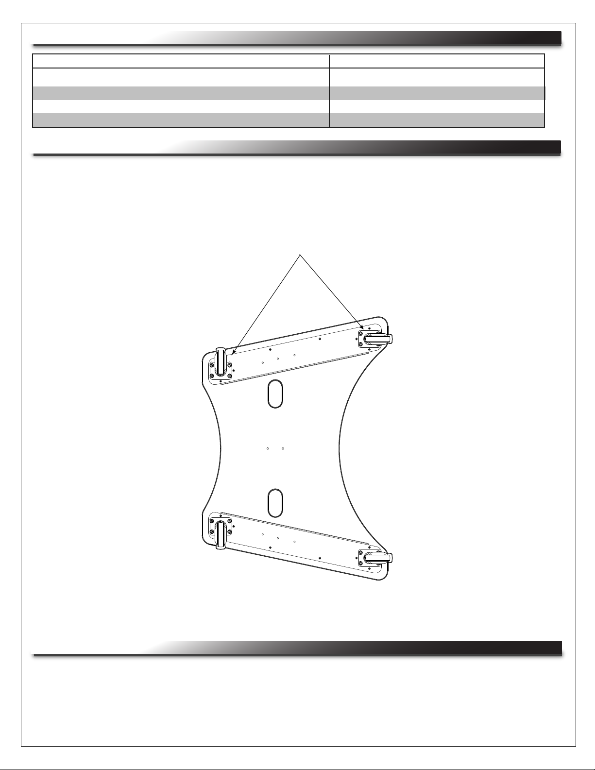
MOBILITY FEATURES
• (4) Directional locking casters are provided to allow easy “steering” of unit in locked direction.
NOTE: Push levers to lock, lift levers to unlock.
To prevent FlexView from moving, lock casters
perpendicular to each other as shown:
TOOLS REQUIRED
• #2 Phillips Screwdriver
• Protective Eyewear
• Adjustable Wrench
• 1/2” Socket
• 7/16” Socket
Page 4
Page 5

HARDWARE/ITEMS SUPPLIED
NOTE: Additional hardware is included
that may not be required for your installation.
#6 Washers For Mounting
Small-Screw Components
To Lever Lock™ (Qty 20)
Plastic Lever Lock™
Locking Rivets (Qty 3)
Cable Management
Clips (Qty 8)
Pan Head Screws 8-32 x 3/8”
(Qty 8)
FLAT PANEL MOUNTING HARDWARE
M4 x 16
M4 x 25
M5 x 12
M5 x 16
M5 x 20
M5 x 25
M5 x 50
M6 x 12
M6 x 20
M8 x 20
(Qty 8)
(Qty 4)
(Qty 8)
(Qty 6)
(Qty 6)
(Qty 4)
(Qty 8)
(Qty 8)
(Qty 6)
(Qty 6)
5/16” Flat Washers
(Qty 10)
5/16”-18 Hex Head
Monitor Mount Bolts
(1/2” Socket Req’d)
(Qty 4)
Thread Depth Indicator
(Qty 1)
Keys (Qty 2)
Vertical Monitor
Mounting Brackets
(Qty 2)
Flange Nuts 5/16” - 18
(Qty 8)
VESA 800 Monitor
Adapter Brackets
(Qty 2)
M8 x 25
M8 x 30
M8 x 35
M8 x 70
1/4” Small Nylon Spacers
(Qty 6)
1/2” Small Nylon Spacers
(Qty 6)
(Qty 6)
(Qty 6)
(Qty 4)
Universal Washers
(Qty 8)
(Qty 4)
1/4” Large Nylon Spacers
(Qty 6)
1/2” Large Nylon Spacers
(Qty 12)
Wire Ties (Qty 12)
Vertical Mounting
Bracket Locking Screws
10-32 x 3/4”
(Qty 2)
1” Nylon Spacers
Page 5
(Qty 6)
Nylon Spacers
(Qty 4)
Level
(Qty 1)
Page 6

FLAT PANEL INSTALLATION
NOTE: Horizontal mounting bracket
is pre-installed on FlexView at top
height. Perform the following steps
to adjust height of horizontal
mounting bracket.
Outer Screws
1/4-20 x 1”
(Qty 2)
1) Remove (2) 1/4”-20 x 1” outer screws and
(2) 1/4”-20 x 1/2” inner screws securing
horizontal mounting bracket to
FlexView. (FIGURE A)
2) Determine appropriate display height
and secure horizontal mounting bracket
to FlexView with (2) 1/4”-20 x 1” outer
screw and (2) 1/4”-20 x 1/2” inner
screws using the available holes for
mounting. (FIGURE A, B)
WARNING! Do not adjust height of
!
horizontal mounting bracket with
display attached.
Inner Screws
1/4”-20 x 1/2”
(Qty 2)
Vertical
Mounting
Brackets
Vertical Mounting
Bracket Locking Screws
10-32 x 3/4” (Qty 2)
Outer Screws (2) 1/4”-20 x 1”
Inner Screws (2)
1/4”-20 x 1/2”
Horizontal
FIGURE A
Mounting Bracket
Vertical Mounting Bracket
Locking Screws (2) 10-32 x 3/4”
Grommets (2)
(Reposition as needed)
FIGURE B
(REAR DOOR REMOVED)
Page 6
Page 7

FLAT PANEL INSTALLATION (CONTINUED)
Selecting The Mounting Hardware To Attach Brackets To Flat Panel
1) Identify the correct diameter screw for the flat
panel threaded inserts. The correct screws
should thread easily and not pull out when
tension is applied.
2) To determine proper screw length, insert thread
depth indicator into a threaded insert on the flat panel.
3) Mark the thread depth indicator 1/8” above the
depth of the threaded insert. (FIGURE C)
4) Select a screw that is shorter than the 1/8” mark
made on the thread depth indicator.
CAUTION! Do not use any screw longer than the 1/8”
!
mark or damage to the flat panel may occur.
Mark 1/8” Above Depth
Threaded Insert
Thread Depth Indicator
FIGURE C
Small Straw
or toothpick
Depth Plus 1/8”
Allowance Mark
Small Straw
or toothpick
Depth Plus 1/8”
Mark Allowance
Universal Washers
Universal washers are designed to accommodate the various M4, M5, M6 and M8 hole sizes found in
flat panels.
Page 7
Page 8

VESA 800 EXTENSION BRACKET INSTALLATION (IF REQUIRED)
1) For monitors that require VESA 800 spacing, the VESA 800 monitor adapter bracket must be
used (not required for VESA 600 or less spacing).
2) Place vertical monitor mounting brackets over VESA 800 adapter bracket studs and secure using
(4) 5/16” -18 flange nuts. (FIGURE D)
VESA 800 Monitor
Adapter Bracket (1)
Vertical Monitor
Mounting Bracket (1)
Flange Nuts
5/16”-18 (4)
FIGURE D
FLAT PANEL INSTALLATION (CONTINUED)
NOTES:
• Place flat panel on soft, flat surface while working.
• Do not place excessive pressure on back of the flat panel.
• Universal washers must be installed between the head of the
mounting screw and the vertical mounting bracket as shown.
(FIGURE E)
Nylon Spacers (FIGURE F, PAGE 9)
Nylon spacers add distance between vertical
mounting bracket and flat panel. They will fit
all supplied screw sizes. The spacers must be
used only when attaching flat panels which have:
• Recessed mount points
• Uneven mount points
Universal
Washers (4)
• Any obstruction near the mount points
• A curved back
Dimples (Face Up)
Universal
Washer
Mounting Screws (4)
M8
M6
M5
M4
NOTES:
• Nylon Spacers must be stacked and oriented as shown.
• Nylon Spacers must only be installed between the
vertical mounting bracket and the flat panel.
Page 8
Vertical Mounting Brackets (2)
FIGURE E
Page 9

FLAT PANEL INSTALLATION (CONTINUED)
Attaching Vertical Mounting Brackets to Flat Panel
NOTE: The brackets are indicated (L) Left and (R) Right.
1) Place the flat panel face down on a soft, flat surface and
identify the number and location of screws.
2) Align the holes on each vertical mounting bracket with the
Mounting Screw
Universal
Washer
Vertical
Mounting
Bracket
threaded inserts on the flat panel. (FIGURE F)
NOTE: To ensure a neat appearance, center vertical
mounting brackets on flat panel. Do not extend
Nylon Spacer
brackets past top or bottom of flat panel.
Flat Panel
3) Secure each vertical mounting bracket with the
FIGURE F
screws and hardware identified in previous
steps. Use a minimum of (2) mounting screws per
vertical mounting bracket.
WARNING! This operation requires two people. Do not release your flat panel until you are certain
!
that the top hook of each vertical mounting bracket is securely seated on the upper rail of the
horizontal mounting bracket.
Hanging the Flat Panel
Vertical Mounting
Bracket
1) Raise the flat panel slightly above the top and
bottom rails on the horizontal mounting bracket.
(FIGURE G)
FIGURE G
Horizontal
Mounting
Bracket
Flat Panel
2) Place the flat panel down slowly, ensuring that
the top and bottom hooks on the vertical
mounting brackets properly engage the horizontal
mounting bracket. (FIGURE G)
3) Check for proper height.
NOTE: Achieving desired height may require
repositioning of horizontal mounting bracket
and / or removal and re-installation of vertical
mounting brackets.
4) Secure vertical mounting bracket to cart using
(2) 10-32 x 3/4” locking screws.
(FIGURE A, PAGE 6)
Page 9
Page 10

DOOR REVERSAL PROCEDURE
1) Lift and twist door hinges to remove door. (FIGURE H)
FIGURE H
2) Remove and reinstall hinge on opposite side. (FIGURE I)
FIGURE I
Page 10
Page 11

Page 11
LEVER LOCK™ TOOL FREE INTERNAL MANAGEMENT SYSTEM
The FlexView comes equipped with the following Lever Lock™ items: (6) LL receptacle brackets,
(2) LL-HC21 horizontal channels, and (1) LL-VP2110 vertical 10” deep plate. Additionally, a “Knobs up
or ”Knobs down” 2-space rail is provided.
Use Receptacle
Brackets To Lace
Cable Bundles
From Top To Bottom
2-Space Rail
Lever Lock™ Plate Installation / Configuration
Use Vertical
Plate To Mount
Small Devices
Use Horizontal
Channels To
Manage Cables
1) Insert the Lever Lock™ plate into the
mating slots in the upper horizontal channel.
(FIGURE J)
2) Secure lock mechanism into the mating slots
in the lower horizontal channel. (FIGURE J)
NOTE: Position the flanges to the outside of
the rack to maximize usability.
Horizontal Channel Installation / Configuration
1) Insert horizontal channels into the mating slots in
the side receptacle brackets. Ensure the lock
mechanism is facing the bottom of the rack.
(FIGURE K)
2) Push horizontal channels into place until
locking mechanism ‘clicks’.
Locking Rivet Installation
FIGURE J
Locking Rivet
1) Install plastic locking rivet into the inner
holes as shown to prevent locking
mechanism from disengaging. (FIGURE L)
Lock Mechanism
FIGURE K
FIGURE L
Page 12

CABLE MANAGEMENT / EQUIPMENT MOUNTING
Cables can be secured to movable clips (provided) using wire ties. Position and secure clips in
channels as necessary using screws. (FIGURE M)
Clip
Cable
Screw
(Knobs Up) 2 Space Rackrail
Middle Atlantic PD-815SC
(8) outlet, 15 amp power strip
Accessory / Storage Trough
with surge and circuit breaker
FIGURE M
WARRANTY
Middle Atlantic Products (the "Company") warrants the FlexView FVS Series for a period of (7) seven years from date of shipment by the
Company.
The Company's entire liability to the purchaser, and the purchaser's (or any other party's) sole and exclusive remedy, under this warranty
shall be limited, at the Company's option, to either (a) return of and refund of the price paid for, or (b) repair or replacement at the
Company's factory of the products purchased, or any part or parts thereof, which the Company has determined to be defective after
inspection thereof at the Company's factory.
This warranty does not cover damage due to acts of God, accident, misuse, abuse or negligence by parties other than the Company, or
any modification or alteration of the products. In addition, this warranty does not cover damage due to improper handling, assembly,
installation or maintenance.
THIS WARRANTY IS IN LIEU OF ALL OTHER WARRANTIES OF ANY KIND, EITHER EXPRESSED OR IMPLIED, INCLUDING, BUT
NOT LIMITED TO, IMPLIED WARRANTIES OF MERCHANTABILITY AND FITNESS FOR A PARTICULAR PURPOSE.
TO THE MAXIMUM EXTENT PERMITTED BY APPLICABLE LAW, IN NO EVENT SHALL THE COMPANY BE LIABLE FOR ANY
SPECIAL, INCIDENTAL, INDIRECT, OR CONSEQUENTIAL DAMAGES WHATSOEVER (INCLUDING, WITHOUT LIMITATION,
DAMAGES FOR LOSS OF BUSINESS PROFITS, BUSINESS INTERRUPTION OR ANY OTHER PECUNIARY LOSS) ARISING OUT OF
THE USE OF THE PRODUCTS PURCHASED, EVEN IF THE COMPANY HAS BEEN ADVISED OF THE POSSIBILITY OF SUCH
DAMAGES. THE COMPANY'S LIABILITY TO THE PURCHASER (OR ANY OTHER PARTY) HEREUNDER, IF ANY, SHALL IN NO
EVENT EXCEED THE PURCHASE PRICE OF THE PRODUCTS PAID TO THE COMPANY.
Corporate Headquarters
Corporate Voice 973-839-1011 - Fax 973-839-1976 / International Voice +1 973-839-8821 - Fax +1 973-839-4982
middleatlantic.com - info@middleatlantic.com
Middle Atlantic Canada
Voice 613-836-2501 - Fax 613-836-2690 / middleatlantic.ca - customerservicecanada@middleatlantic.ca
Factory Distribution
USA: NJ - CA - IL Canada: ON - BC
At Middle Atlantic Products we are always listening. Your comments are welcome.
Middle Atlantic Products is an ISO 9001 and ISO 14001 Registered Company.
Page 12
 Loading...