

Page 1
Instruction Sheet
CWR SERIES
CABLESAFETM WALL CABINET
U
R
C US
LISTED
L
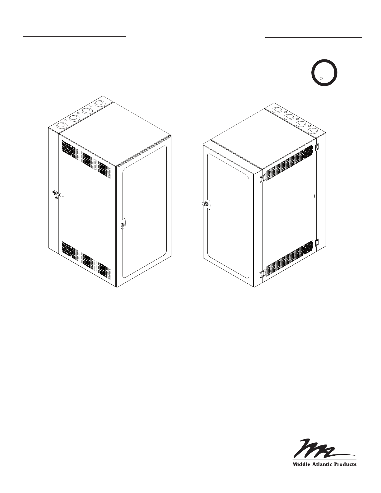
CABLESAFE WALL CABINET WITH
STANDARD DOOR
THANK YOU
Thank you for purchasing the CWR Series CableSafe Cabling Wall Cabinet. Please read these
instructions thoroughly before installing/assembling this product.
PRODUCT FEATURES
- 26” width provides abundant space for patching
- Ships with front rackrail at a 4” setback to accomodate cable managers
- Swing open center section allows for easy front and rear access to equipment and cabling
- Available with vented, plexiglass or solid doors
CABLESAFE WALL CABINET WITH
4” DEEP DOOR
I-00347 Rev B
Page 2
IMPORTANT SAFETY INSTRUCTIONS
• Read these instructions.
• Keep these instructions.
• Heed all warnings.
• Follow all instructions.
• Clean only with dry cloth.
• Only use attachments/accessories specified by the manufacturer.
WARNING: A WARNING ALERTS YOU TO A SITUATION
!
THAT COULD RESULT IN SERIOUS PERSONAL INJURY
OR DEATH.
CAUTION: A CAUTION ALERTS YOU TO A SITUATION
!
THAT MAY RESULT IN MINOR PERSONAL INJURY OR
DAMAGE TO THE PRODUCT AND / OR PROPERTY.
NOTE: A NOTE IS USED TO HIGHLIGHT PROCEDURES
PERTAINING TO THE INSTALLATION, OPERATION OR
MAINTENANCE OF THE PRODUCT.
IMPORTANT WARNINGS AND CAUTIONS!
WARNING! Failure to read, understand and follow the following information can result in serious personal injury, damage to the
!
equipment or voiding of the warranty.
CAUTION: All installation and assembly steps must be performed by qualified personnel.
!
CAUTION: Ensure that the wall/floor has a structural load capacity that will support the weight of the cabinet fully loaded with
!
equipment.
CAUTION: Some parts of the enclosure system may not be effectively bonded to the Protective Earth Terminal (PET). If these parts
!
need to be bonded to the PET it should be done in accordance with Article 250 of the National Electrical Code.
CAUTION: Power cord(s), for fans or other accessories, need to be secured to ensure that they are routed away from pinch points
!
and moving parts.
CAUTION: Do not attempt to unload or move the enclosures alone. Make sure to have sufficient amount of personnel and
!
equipment to safely move this product.
CAUTION: The following parts are not effectively bonded to the protective earth terminal: Rackrails, lace bars, Lever Lock™,
!
shelving, baffles, blank panels, and cable management equipment. If any part needs to be bonded to the protective earth terminal
it shall be done in accordance with Article 250 of the National Electrical Code.
!
CAUTION: Maximum weight capacity is 200 lbs. As a general rule, heavier equipment should be placed towards the bottom of the
!
rack.
TOOLS REQUIRED
• 5/16” Wrench
• 5/16” Socket
• 5/32” Hex Key
SUPPLIED HARDWARE
STANDARD D-RING 8-32 ACORN NUT 8-32 STUD
12-24 RACKSCREW
12 SPACE
18 SPACE
26 SPACE
QTY QTY QTY QTY
4 4 4 50
6 6 6 50
8 8 8 50
Page 3
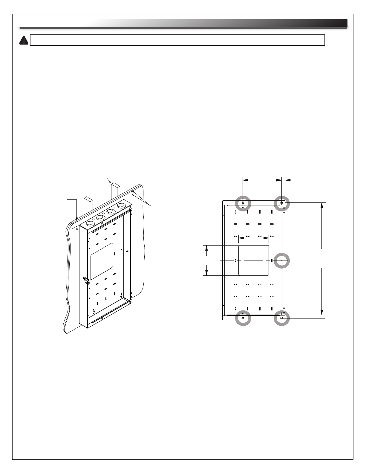
CABINET INSTALLATION
THE CABINET MUST BE INSTALLED PLUMB AND LEVEL FOR PROPER OPERATION.
!
1) Separate backpan from center section and determine hinge side.
NOTE: CWR center section can be opened from left-to-right or vice versa depending on how backpan
is installed.
NOTE: Ensure the wall to which the backpan will be mounted, consists of two (2) 3/4" plywood
screwed to the studs.
2) Locate the studs in the wall behind the two (2) ¾” plywood. Align the mounting holes in the cabinet
with the studs. Using 3/8” diameter lag bolts with a minimum length of 2” and flat washers in each
mounting hole, secure the cabinet to the wall.
NOTE: A minimum of 1” clearance on the top and bottom of the cabinet is required. (FIGURE A)
5 MOUNTING HOLES CIRCLED
STUD
16” 1 ½”
MIN. 1”
CLEARANCE
REQUIRED
TOP AND
BOTTOM
TWO 3/4”
PLYWOOD
NOTE: Center section removed for clarity
FIGURE A
12 ½”
12 ½”
21 ⅞”
32 ⅜”
46 ⅜”
CWR-12
CWR-18
CWR-26
Page 3
Page 4

GROUNDING AND BONDING
Protective Earth Terminals (PET) are located in backpan of the wall rack. These terminals are marked with the symbol
Wall rack parts, center section and door, contain or are provided with bonding points for connection to the backpan / PET.
Protective earth and bonding connections shall be in accordance with Article 250 of the National Electric Code.
OPTIONAL PROTECTIVE EARTH TERMINAL KIT: #PET-K-CWR
PARTS LIST
• Backpan bonding wire [12 Gauge Wire
(#10 ring terminal to 1/4” ring terminal] 9”]
• Door bonding wire [12 Gauge Wire
(#10 ring terminal to #10 ring terminal) 9”]
• Thread forming screw M4 x .7
• Locking Nut 10-32
• Flange Nut 1/4-20
QTY
(1)
(1)
(1)
(3)
(1)
(1) (1)
(3)
(1) (1)
Page 4
Page 5

GROUNDING AND BONDING (Continued)
1) Attach backpan bonding wire from 1/4”-20 backpan protective earth terminal (PET) to nearest
center section bonding stud (10-32) using hardware provided. (FIGURE G)
NOTE: The main protective earth ground needs to be the first terminal placed on the PET and this
terminal needs to be secured on its own with a nut. The bonding wire for the center section can
be added to the PET after securing the nut for the main ground. (FIGURE G)
2) Attach door bonding wire (with male or female disconnect end) to door bonding stud with
nut (included). (FIGURE G)
3) Attach remaining door bonding wire to nearest center section bonding stud (10-32) using hardware
provided. (FIGURE G)
4) Connect male and female ends of door bonding wire set.
Center Section
SIDE VIEW
Center Section Bonding Studs
10-32 (2 Per Side)
Backpan
FIGURE G
Backpan
PET Stud
Door
FRONT VIEW
Door
Bonding
Stud
Page 4
Page 6

D-RING INSTALLATION
1) Install the supplied D-Rings to the pre-installed rackrail on both sides of the rack as shown with the
supplied hardware. (FIGURE B)
8-32 STUD
8-32 ACORN
NUT
D-RING RACKRAIL
STANDARD DOOR SWING REVERSAL
FIGURE B
1) Remove the two (2) 10-32 screws from both top and bottom hinges to remove the door (remove 4 screws total).
(FIGURE C)
2) Reverse the door to install to the opposite side of the rack. Install the two (2) 10-32 screws to the top and
bottom hinges.
HINGE
10-32
SCREWS
FIGURE C
Page 5
Page 7

4” DEEP DOOR SWING REVERSAL
1) Remove the 1/4-20 panhead screws and flange nuts from the top and bottom hinges to remove
the door. (FIGURE D)
FLANGE NUT
HINGE
1/4-20 PANHEAD
FIGURE D
SCREWS
2) Remove the extended latch by removing the (2) two 10-32 screws. Install the latch to the opposite side of the
rack. (FIGURE E)
10-32
SCREWS
LATCH
EXTENDER
FIGURE E
Page 6
Page 8

NYLON PUSH RIVET 20
4” DEEP DOOR SWING REVERSAL (Continued)
3) Reverse the door to install it to the opposite side of the rack using (2) two 1/4-20 panhead screws and (2) two
1/4-20 flange nuts per hinge (top and bottom). (FIGURE F)
FLANGE NUT
1/4-20
PANHEAD
SCREWS
HINGE
FIGURE F
OPTIONAL COOLING KIT
CWR FAN KIT
PART NO. DESCRIPTION QTY
CWR-FKIT FANS (95 CFM per fan) 2
CORDS 2
GUARDS 2
VENT BLOCKER 1
Page 7
Page 9

WARRANTY
Middle Atlantic Products (the "Company") warrants the CWR Series Cabling Wall Rack to be free
from defects in material or workmanship under normal use and conditions for the lifetime of the
product.
The Company's entire liability to the purchaser, and the purchaser's (or any other party's) sole and
exclusive remedy, under this warranty shall be limited, at the Company's option, to either (a) return of
and refund of the price paid for, or (b) repair or replacement at the Company's factory of the products
purchased, or any part or parts thereof, which the Company has determined to be defective after
inspection thereof at the Company's factory.
This warranty does not cover damage due to acts of God, accident, misuse, abuse or negligence by
parties other than the Company, or any modification or alteration of the products. In addition, this
warranty does not cover damage due to improper handling, assembly, installation or maintenance.
THIS WARRANTY IS IN LIEU OF ALL OTHER WARRANTIES OF ANY KIND, EITHER EXPRESSED OR
IMPLIED, INCLUDING, BUT NOT LIMITED TO, IMPLIED WARRANTIES OF MERCHANTABILITY AND
FITNESS FOR A PARTICULAR PURPOSE.
TO THE MAXIMUM EXTENT PERMITTED BY APPLICABLE LAW, IN NO EVENT SHALL THE COMPANY
BE LIABLE FOR ANY SPECIAL, INCIDENTAL, INDIRECT, OR CONSEQUENTIAL DAMAGES
WHATSOEVER (INCLUDING, WITHOUT LIMITATION, DAMAGES FOR LOSS OF BUSINESS PROFITS,
BUSINESS INTERRUPTION OR ANY OTHER PECUNIARY LOSS) ARISING OUT OF THE USE OF THE
PRODUCTS PURCHASED, EVEN IF THE COMPANY HAS BEEN ADVISED OF THE POSSIBILITY OF
SUCH DAMAGES. THE COMPANY'S LIABILITY TO THE PURCHASER (OR ANY OTHER PARTY)
HEREUNDER, IF ANY, SHALL IN NO EVENT EXCEED THE PURCHASE PRICE OF THE PRODUCTS
PAID TO THE COMPANY.
Corporate Headquarters
Corporate Voice 973-839-1011 - Fax 973-839-1976
International Voice +1 973-839-8821 - Fax +1 973-839-4982
middleatlantic.com - info@middleatlantic.com
Middle Atlantic Canada
Voice 613-836-2501 - Fax 613-836-2690
middleatlantic.ca - customerservicecanada@middleatlantic.ca
Factory Distribution
USA: NJ - CA - IL Canada: ON - BC
At Middle Atlantic Products we are always listening. Your comments are welcome.
Middle Atlantic Products is an ISO 9001 and ISO 14001 Registered Company.
 Loading...