

Page 1
assembly instructions
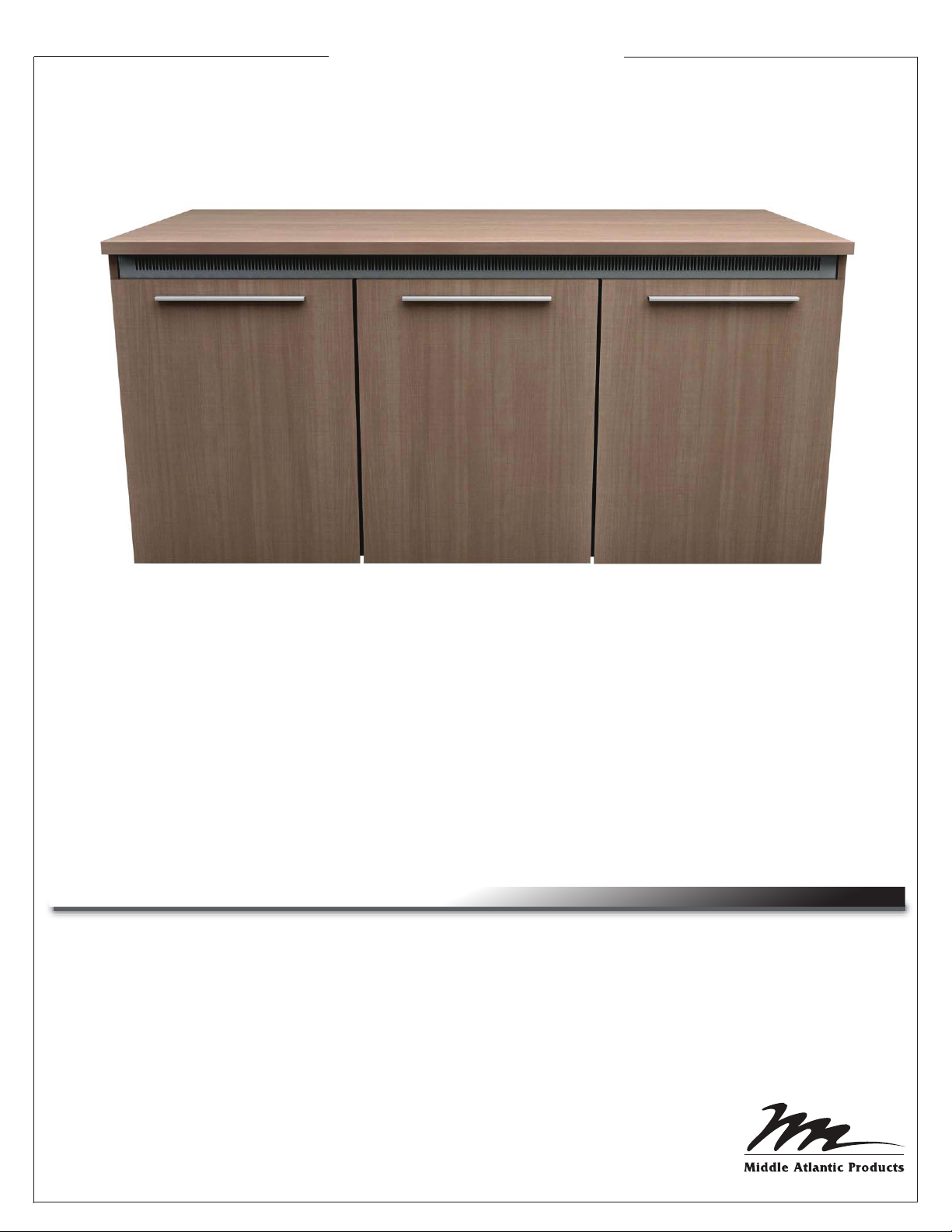
C5 SERIES
CREDENZA RACK
Thank you for purchasing the C5 Series Credenza Rack. Please read all instructions thoroughly
before assembling this product.
PRODUCT FEATURES
- Built-in thermostatically controlled cooling.
- Heavy duty frame ships separate to allow for equipment integration before finished surfaces are
attached.
- 14 rackspaces per bay.
- Factory installed casters.
- Weight rating of 800 pounds, including finishing kit*, with maximum 350 pounds located on
top surface. (*Middle Atlantic Products supplied finishing kit is 200 pounds complete)
I-00661 Rev E
Page 2
WARNINGS
WARNING - Death or serious injury may occur when children climb on audio and/or video equipment urniture. A remote control or
!
toys placed on the furnishing may encourage a child to climb on the furnishing and as a result the furnishing may tip over on to the child.
AVERTISSEMENT - La mort ou la blessure sérieuse peut se produire quand les enfants s'élèvent sur des meubles d'audio et/ou de
!
matériel vidéo. Un à télécommande ou les jouets placés sur la fourniture peut encourager un enfant à s'élever sur la fourniture et en
conséquence la fourniture peut incliner plus de dessus à l'enfant.
!
WARNING - Relocating audio and/or video equipment to furniture not specifically designed to support audio and/or video equipment
may result in death or serious injury due to the furnishing collapsing or over turning onto a child.
!
AVERTISSEMENT - Replacer l'audio et/ou le matériel vidéo aux meubles pas spécifiquement conçus pour soutenir l'audio et/ou le
matériel vidéo peut avoir comme conséquence la mort ou la blessure sérieuse due à s'effondrer de fourniture ou au-dessus de la
rotation sur un enfant.
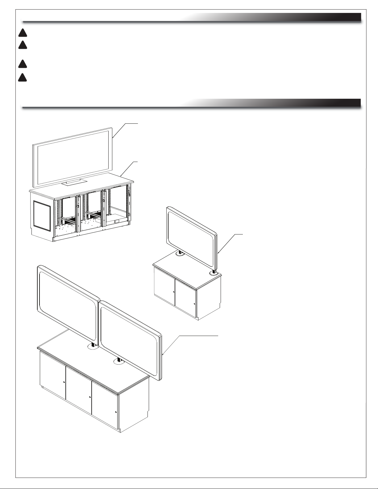
WEIGHT DISTRIBUTION/MONITOR SIZING
Monitor may be free standing for 1, 2 or 3 bay units.
When using free standing monitors, monitors must not
extend beyond the width of work surface:
1 Bay = 23.50 “ [596.9mm]
2 Bay = 45.88” [1165.35mm]
3 Bay = 68.25“ [1733.55mm]
All units (1,2 or 3 bay) have a total maximum
equipment weight capacity of 600 lbs [272.15 Kg]
with a top work surface maximum weight
capacity of 350 lbs [158.76 Kg]
For 2 Bay using optional monitor mount kit:
Largest single monitor size: 80” [2032mm] diagnal
225 LB [102.06 Kg] Max weight
For 3 Bay using optional monitor mount kit:
Largest single monitor size: 80” [2032mm] diagnal
225 lbs [102.06 Kg] Max weight
Largest dual monitors: 65” [1651mm] diagnal
320 lbs [145.15 Kg] Max Weight
WARNING - Risk of Collapse and Instability. This enclosure is intended for use only with the equipment and maximum weights indicated.
Use with other equipment or equipment heavier than the maximum weights indicated may result in instability causing possible injury.
AVERTISSEMENT - Risque d'effondrement et d'instabilité. Ce enceinte est prévu pour l'usage seulement avec l'équipement et
les poids maximum indiqués. L'utilisation avec l'autre équipement ou l'équipement plus lourd que les poids maximum indiqués peut avoir
comme conséquence l'instabilité causant la blessure possible.
Page 2
Page 3

FAN NOTES
TURN ON TEMPERATURE: The blower will turn on at 87° F (30.5° C) and run proportionately.
Speed increases with temperature from 87° F (30.5° C) to 95° F (35° C). At 95° F (35° C) and above,
the blower will run at full speed. The blower will stop running at 85° F (29.4° C).
A) TEMPERATURE PROBE: Temperature detection probe (A).
(A)
NOTE: Locate probe near hottest equipment.
NOTE: Blue LED in exhaust area illuminates when the unit is receiving power.
Use obrounds for cable tie points
Page 3
Page 4

VENT INSTALLATION
1) Place vent underneath the flange. (FIGURE A)
2) Using a #2 Phillips driver, install the 10-32 screws into the top of the vent (FIGURE A).
Use hardware kit #91-00507.
FIGURE A
Page 4
Page 5

SIDE PANEL INSTALLATION
NOTE: For accessories related to the Side Panels, please read those instructions thoroughly before
continuing with the installation below
1) Install side panels by placing the four pre-installed hooks into the four slots on the frame. (FIGURE B)
NOTE: When installing side panels, ensure door hinge plates are located at the front of the frame.
Door Hinge Plate
FIGURE B
Page 5
Page 6

HARDWARE KIT QTY
Qty (All models get one
Configuration Hardware Kit
1-Bay 91-00514
2-Bay 91-00515
3-Bay 91-00516
Sub-Hardware Kits
91-00508/91-00518
91-00508/91-00518
91-00508/91-00518
91-00517)
1
2
3
TOP SURFACE INSTALLATION
NOTE: For accessories related to the Top Surface, please read those instructions thoroughly before
continuing with the installation below
NOTE: If installing a monitor mount, please read the instructions with the monitor mount prior to
installing.
1) Align the top using wooden dowels in the side panels as a guide. Attach top surface to the frame
using provided wood screws (HW Kit #91-00517), extra screws provided. (FIGURE C)
FIGURE C
Number of #10 x 5/8” Screws Used Per Credenza Top
Configuration Screws
3-Bay 12
2-Bay 8
1-Bay 4
Page 6
Page 7

DOOR INSTALLATION
1) Install doors using provided wood screws (two places per door) as shown (HW Kit #91-00518).
(FIGURE D)
(NOTE:
Factory Installed Bumpers
(3) Three replacement bumpers supplied)
FIGURE D
Page 7
Page 8

DOOR INSTALLATION ONTO MULLION
1) Door to be installed onto credenza frame using provided screws (two places per door) as shown
(HW Kit #91-00518). (FIGURE E)
FIGURE E
Page 8
Page 9

LOCK/KNOB INSTALLATION
1) Install lock/knob into pre-drilled pilot holes. (FIGURE F)
FIGURE F
HINGE ADJUSTMENTS
1
3
1
2
3
2
1
Door in open position
FIGURE G
Directional adjustments apply to the door in the closed position. Hinge adjustment is done with door in
open position. Refer to (FIGURE G) for appropriate adjustments.
1
Side Adjustment: Adjusts horizontal placement of door. Adjusts door-to-door gap.
Height Adjustment: Adjusts vertical height of door.
2
Depth Adjustment: Adjusts the space between the door and the face of the frame of credenza.
3
Page 9
Page 10

SPRING LATCH INSTALLATION
1) Install latch using provided screws (two places per latch) as shown (HW Kit #91-00508). (FIGURE H)
NOTE: When installing a latch into the mullion, use the provided machine screws. If installing into wood,
use provided wood screws.
FIGURE H
WARRANTY
Middle Atlantic Products, Inc. (the "Company") warrants the C5 Credenza Frame to be free from defects in material or workmanship under normal use and conditions for the lifetime
of the product, the Cladding for (7) seven years, and the Fans for (3) three years from the date of shipment by the Company.
The Company's entire liability to the purchaser, and the purchaser's (or any other party's) sole and exclusive remedy, under this warranty shall be limited, at the Company's option, to either (a) return of and
refund of the price paid for, or (b) repair or replacement at the Company's factory of the products purchased, or any part or parts thereof, which the Company has determined to be defective after inspection
thereof at the Company's factory.
This warranty does not cover damage due to acts of God, accident, misuse, abuse or negligence by parties other than the Company, or any modification or alteration of the products. In addition, this warranty
does not cover damage due to improper handling, assembly, installation or maintenance.
THIS WARRANTY IS IN LIEU OF ALL OTHER WARRANTIES OF ANY KIND, EITHER EXPRESSED OR IMPLIED, INCLUDING, BUT NOT LIMITED TO, IMPLIED WARRANTIES OF MERCHANTABILITY
AND FITNESS FOR A PARTICULAR PURPOSE.
TO THE MAXIMUM EXTENT PERMITTED BY APPLICABLE LAW, IN NO EVENT SHALL THE COMPANY BE LIABLE FOR ANY SPECIAL, INCIDENTAL, INDIRECT, OR CONSEQUENTIAL DAMAGES
WHATSOEVER (INCLUDING, WITHOUT LIMITATION, DAMAGES FOR LOSS OF BUSINESS PROFITS, BUSINESS INTERRUPTION OR ANY OTHER PECUNIARY LOSS) ARISING OUT OF THE USE
OF THE PRODUCTS PURCHASED, EVEN IF THE COMPANY HAS BEEN ADVISED OF THE POSSIBILITY OF SUCH DAMAGES. THE COMPANY'S LIABILITY TO THE PURCHASER (OR ANY OTHER
PARTY) HEREUNDER, IF ANY, SHALL IN NO EVENT EXCEED THE PURCHASE PRICE OF THE PRODUCTS PAID TO THE COMPANY.
International Voice +1 973-839-8821 - Fax +1 973-839-4982 middleatlantic.ca - customerservicecanada@middleatlantic.ca
middleatlantic.com - info@middleatlantic.com
Page 10
noitubirtsiD yrotcaF adanaC citnaltA elddiM sretrauqdaeH etaroproC
CB - NO :adanaC LI - AC - JN :ASU 0962-638-316 xaF - 1052-638-316 ecioV 6791-938-379 xaF - 1101-938-379 ecioV etaroproC
 Loading...