

Page 1
Instruction Sheet
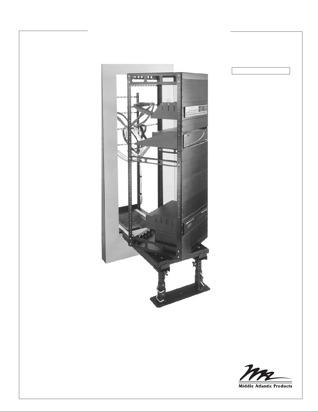
AX-SXR SERIES
Rotating Equipment Access System
PATENT 5,443,312
THANK YOU
Thank you for purchasing the AX-SXR Series Rotating Equipment Access System. Please read these
instructions thoroughly before installing / assembling this product.
PRODUCT FEATURES
- Slides out and rotates for access to cables and rear equipment connections
- Allows installation of equipment flush into a wall or cabinet
- Removable rack frame can be integrated off-site to save time
I-00073 Rev E
Page 2

Page 3

IMPORTANT SAFETY INSTRUCTIONS
• Read these instructions.
• Keep these instructions.
• Heed all warnings.
• Follow all instructions.
• Clean only with dry cloth.
• Only use attachments/accessories specified by the manufacturer.
IMPORTANT WARNINGS AND CAUTIONS!
WARNING! FAILURE TO READ, UNDERSTAND AND
!
FOLLOW THE FOLLOWING INFORMATION CAN
RESULT IN SERIOUS PERSONAL INJURY, DAMAGE TO
THE EQUIPMENT OR VOIDING OF THE WARRANTY. IT
IS THE RESPONSIBILITY OF THE INSTALLER/USER TO
ENSURE THAT THIS PRODUCT IS LOADED
ACCORDING TO SPECIFICATIONS.
WARNING! THE WEIGHT RATINGS OF THIS PRODUCT
!
CAN BE FOUND ON THE PRODUCT. EXCEEDING
THESE WEIGHT RATINGS CAN RESULT IN SERIOUS
INJURY OR DAMAGE TO THE EQUIPMENT. IT IS
THE RESPONSIBILITY OF THE INSTALLER/USER TO
ENSURE ALL COMPONENTS INSTALLED DO NOT
SURPASS THE WEIGHT RATINGS AS AN UNSTABLE
CONDITION CAN OCCUR WHICH MAY CAUSE
POSSIBLE INJURY OR DAMAGE.
CAUTION! IF THERE IS VISIBLE DAMAGE ON THE
!
PRODUCT IT MUST NOT BE INSTALLED.
WARNING: A WARNING ALERTS YOU TO A SITUATION
!
THAT COULD RESULT IN SERIOUS PERSONAL INJURY
OR DEATH.
CAUTION: A CAUTION ALERTS YOU TO A SITUATION
!
THAT MAY RESULT IN MINOR PERSONAL INJURY OR
DAMAGE TO THE PRODUCT AND / OR PROPERTY.
NOTE: A NOTE is used to highlight procedures pertaining
to the installation, operation or maintenance of the product.
CAUTION! SAFETY MEASURES MUST BE PRACTICED
!
AT ALL TIMES DURING THE ASSEMBLY OF THIS
PRODUCT. USE PROPER SAFETY EQUIPMENT
AND TOOLS FOR THE ASSEMBLY PROCEDURE TO
PREVENT PERSONAL INJURY.
CAUTION! NOTE THAT DURING CONSTRUCTION OF
!
THE CONSOLE, THERE MUST BE NO POSSIBILITY OF
PERSONAL INJURY, FOR EXAMPLE THE SQUEEZING
OF FINGERS OR ARMS.
CAUTION! FOR LOADING, ALWAYS PUT HEAVIER
!
ITEMS AT THE BOTTOM OF THE BAYS, NOT NEAR THE
TOP, IN ORDER TO HELP PREVENT THE POSSIBILITY
OF THE FURNISHING TIPPING OVER.
CAUTION! THE APPLIANCE IS NOT INTENDED FOR
!
USE BY YOUNG CHILDREN OR INFIRM PERSONS
WITHOUT SUPERVISION.
Page 3
Page 4

TABLE OF CONTENTS
Important Safety Instructions....................................................................................... 3
Rough-In / Site Preparation
Millwork Requirements
Rack Assembly
Rack Assembly (Continued)
Rack Assembly (Continued)
Service Stand / Service Track Assembly
Rack and Cable Carrier Installation / Cable Management
Securing Rack Assembly In Millwork
Warranty
............................................................................................................. 13
...................................................................................................... 7
......................................................................................... 5
.............................................................................................. 6
........................................................................................ 8
........................................................................................ 9
........................................................................... 10
............................................................................... 12
......................................................... 11
Page 4
Page 5

ROUGH-IN / SITE PREPARATION
1) Rough-in millwork must be plumb, square and completed before beginning assembly. Refer to
millwork mounting requirements below.
WIDTH
MINIMUM
MAXIMUM
9 1/4”
9 1/4”
2" [51 mm] Minimum
Recommended
Cable Clearance
25.50" [648 mm]
Minimum Depth
With .50” [13 mm]
Setback
or
27.50" [649 mm]
Minimum Depth With
2.50" [64 mm] Setback
DEPTH
25 1/2”
27 1/2’
SETBACK
1/2”
2 1/2”
20" [508 mm]
19.25" [489 mm]
Minimum Rough
Opening
In Millwork
A* B*
23”
[584 mm]
3" [76 mm]
Minimum
40" [1016 mm]
Maximum
.50" [13 mm] Minimum
2.50" [66 mm] Maximum
Setback
Track
31”-31" [787 mm]
* Refer to following page for specific model height requirements.
NOTE: The millwork must be constructed in such a manner as to provide a weight capacity greater than
the total assembled weight.
Page 5
Page 6

MILLWORK REQUIREMENTS
AX-SXR-15
AX-SXR-16
AX-SXR-17
AX-SXR-18
AX-SXR-19
AX-SXR-20
AX-SXR-21
AX-SXR-22
AX-SXR-23
AX-SXR-24
AX-SXR-25
AX-SXR-26
AX-SXR-27
AX-SXR-28
AX-SXR-29
AX-SXR-30
AX-SXR-31
AX-SXR-32
AX-SXR-33
AX-SXR-34
AX-SXR-35
AX-SXR-36
AX-SXR-37
AX-SXR-38
AX-SXR-39
AX-SXR-40
AX-SXR-41
AX-SXR-42
AX-SXR-43
NUMBER OF
USABLE
RACKSPACES
15
16
17
18
19
20
21
22
23
24
25
26
27
28
29
30
31
32
33
34
35
36
37
38
39
40
41
42
43
“A”
USABLE
RACK HEIGHT
26-1/4 [667]
28 [711]
29-3/4 [756]
31-1/2 [800]
33-1/4 [845]
35 [889]
36-3/4 [933]
38-1/2 [978]
40-1/4 [1022]
42 [1067]
43-3/4 [1111]
45-1/2 [1156]
47-1/4 [1200]
49 [1245]
50-3/4 [1289]
52-1/2 [1334]
54-1/4 [1378]
56 [1422]
57-3/4 [1467]
59-1/2 [1511]
61-1/4 [1556]
63 [1600]
64-3/4 [1645]
66-1/2 [1689]
68-1/4 [1734]
70 [1778]
71-3/4 [1822]
73-1/2 [1867]
75-1/4 [1911]
“B”
ROUGH
OPENING HEIGHT
33 [838]
34-3/4 [883
]36-1/2 [927]
38-1/4 [972]
40 [1016]
41-3/4 [1060]
43-1/2 [1105]
45-1/4 [1149]
47 [1194]
48-3/4 [1238]
50-1/2 [1283]
52-1/4 [1327]
54 [1372]
55-3/4 [1416]
57-1/2 [1461]
59-1/4 [1505]
61 [1549]
62-3/4 [1594]
64-1/2 [1638]
66-1/4 [1683]
68 [1727]
69-3/4 [1772]
71-1/2 [1816]
73-1/4 [1861]
75 [1905]
76-3/4 [1949]
78-1/2 [1994]
80-1/4 [2038]
82 [2083]
NOTE: Total rack height including rough-in pan is the usable rack height ("A") plus 4-9/16."
Page 6
Page 7

RACK ASSEMBLY
1) Align the (4) pre-installed mounting studs on each rackrail with mounting holes in top and bottom
frames. (FIGURE A)
2) Loosely secure each rackrail to top and bottom frame using (2) 5/16” flange nuts per frame.
(FIGURE A)
Top Frame
Rackrail
Mounting Studs
(4 Per Rackrail)
5/16 Flange Nuts
(4 Per Rackrail)
Bottom Frame
FIGURE A
Page 7
Page 8

RACK ASSEMBLY (Continued)
3) Install (4) 10-32 Hex Head screws through top and bottom frames into each rackrail. (FIGURE B)
4) Install (2) squaring panels on front and rear of assembly using (4) 10-32 x 1/4” screws. Locate
squaring panels at the mid-point of rackrail assembly. (FIGURE B)
5) If supplied, install (2) support brackets on pre-installed rackrail mounting studs using (2) 10-32 hex
head screws per bracket. (FIGURE B)
6) Lay assembly on a flat, level surface and square frame on all four corners. (FIGURE C)
7) Tighten all flange nuts.
Top Frame
Hex Head
Screws 10-32
(2 Per Support
Bracket)
Support
Brackets
(2)
Squaring
Panels
(2)
(INCORRECT)
8) Attach the bottom of the rack to the roller
base using the 1/2” shoulder screw provided
and tighten. (FIGURE D)
Hex Head
Screws 10-32
(4 Per Rackrail)
SHOULDER
SCREW
(CORRECT)
FIGURE C
FIGURE D
Screws 10-32
(4 Per Squaring
Panel)
Rackrail
Bottom Frame
FRONT
NOTE: The stud on the bottom of the rack needs
to fall into the slot on the roller base before
inserting the shoulder screw.
EQUIPMENT LOADING AND SQUARING PANELS
To eliminate the possibility of a center bow in the
frame, Middle Atlantic Products suggests that the
squaring panels be left in place until some of your
components have been mounted.
FIGURE B
Page 8
Page 9

RACK ASSEMBLY (Continued)
8) Install top trim panel using (2) 10-32 x 1/4” screws. (FIGURE E)
NOTE: Top trim panel contains only two screw holes.
9) If equipped, align the edge of the lacer bars with the
outside edge of the rackrail and ensure that the flat
side of the lacer bar is on top. Install the lacer bars
as shown using 10-32 Phillips head screws. (FIGURE F)
NOTE: The lacer bars should not be placed in the
bottom 8 rackspaces. The lacer bars on
the rack should be 2 rackspace above or below
the corresponding lacer bars on the rough-in pan.
TIP: When installing the lacer bars on the rough-in
pan, place the rack with the roller base on the
Screws (2)
10-32 x 1/4”
rough-in pan and mount the equipment in the rack
and position the lacer bars as needed. This will
simplify cable management once the rough-in pan
is mounted into the millwork. (FIGURE G)
Lacer Bars
Top Trim Panel
FIGURE E
Lacer BarRackrail
FIGURE F
Rough-In Pan
FIGURE G
Page 9
Page 10

SERVICE STAND / SERVICE TRACK ASSEMBLY
1) Assemble service stand as per instructions
included with unit.
2) Adjust stand to approximate height of
rough-in pan. (FIGURE H)
3) Position notched end of each service track on
service stand saddles. (FIGURE H)
CAUTION! Be sure notched ends are
!
fully seated in service stand saddles
to prevent tracks from falling out.
Notches
Service
Tracks
4) Position opposite end of each service
track on millwork. (FIGURE H)
5) Secure each service track to rough-in
pan using (2) 10-32 hex head
screws (included in service
track hardware kit). (FIGURE I)
Hex Head
Screws
(2 Per Track)
10-32
FIGURE I
Saddle
Service
Stand
Rough-in
Pan
Saddle
FIGURE H
Slide Support Screws
(2 Per Track)
6) Fine adjust the service stand with
the aid of the level installed in the
Support
service tracks.
FIGURE J
7) Extend slide supports on each service
track to meet millwork using slide
support screws (2 per service track).
(FIGURE J)
NOTE: This adjustment strengthens track when extending heavy equipment for servicing.
Page 10
Slide
Page 11

RACK INSTALLATION / CABLE MANAGEMENT
1) Place rack on service track assembly (observe proper front/rear orientation). (FIGURE K)
CAUTION! Do not allow the frame to roll off end of tracks.
NOTE: Determine which direction the rack will rotate before beginning cable management.
2) Select one side of the rack for signal cables, and the opposite side for power cables. Extend the
rack and rotate 60º as shown. Lace the cables as shown, ensuring that the cables are taut. This
ensures that the service loop will be the correct length and not be pinched when closing the rack.
(FIGURE L)
FIGURE K
Page 11
FIGURE L
Page 12

SECURING RACK ASSEMBLY IN MILLWORK
1) Roll loaded rack into millwork.
2) Install bottom trim panel using (4) 10-32 Phillips head screws (included in hardware kit). (FIGURE M)
WARNING! The trim panel is integral to the safe operation of this product and is required to
prevent the rack from sliding out. Failure to install trim panel can result in serious damage to
equipment and/or risk of injury.
3) Remove tracks and service stand.
Bottom
Trim Panel
Phillips Head
Screws (4)
10 -32 x 1/4”
FIGURE M
NOTE: If the loaded rack frame springs outward during installation,
it can be secured directly to the millwork wherever a blank panel is
located. With rack closed, remove blank panel and install
customer-supplied screws through each side of front rackrail
into millwork. (FIGURE N)
Screws (2)
FIGURE N
Page 12
Page 13

WARRANTY
Middle Atlantic Products (the "Company") warrants the AX-SXR Rotating Equipment Access System
to be free from defects in material or workmanship under normal use and conditions for a period of (3)
years from the date of shipment by the company.
The Company's entire liability to the purchaser, and the purchaser's (or any other party's) sole and
exclusive remedy, under this warranty shall be limited, at the Company's option, to either (a) return of
and refund of the price paid for, or (b) repair or replacement at the Company's factory of the products
purchased, or any part or parts thereof, which the Company has determined to be defective after
inspection thereof at the Company's factory.
This warranty does not cover damage due to acts of God, accident, misuse, abuse or negligence by
parties other than the Company, or any modification or alteration of the products. In addition, this
warranty does not cover damage due to improper handling, assembly, installation or maintenance.
THIS WARRANTY IS IN LIEU OF ALL OTHER WARRANTIES OF ANY KIND, EITHER EXPRESSED OR
IMPLIED, INCLUDING, BUT NOT LIMITED TO, IMPLIED WARRANTIES OF MERCHANTABILITY AND
FITNESS FOR A PARTICULAR PURPOSE.
TO THE MAXIMUM EXTENT PERMITTED BY APPLICABLE LAW, IN NO EVENT SHALL THE COMPANY
BE LIABLE FOR ANY SPECIAL, INCIDENTAL, INDIRECT, OR CONSEQUENTIAL DAMAGES
WHATSOEVER (INCLUDING, WITHOUT LIMITATION, DAMAGES FOR LOSS OF BUSINESS PROFITS,
BUSINESS INTERRUPTION OR ANY OTHER PECUNIARY LOSS) ARISING OUT OF THE USE OF THE
PRODUCTS PURCHASED, EVEN IF THE COMPANY HAS BEEN ADVISED OF THE POSSIBILITY OF
SUCH DAMAGES. THE COMPANY'S LIABILITY TO THE PURCHASER (OR ANY OTHER PARTY)
HEREUNDER, IF ANY, SHALL IN NO EVENT EXCEED THE PURCHASE PRICE OF THE PRODUCTS
PAID TO THE COMPANY.
Corporate Headquarters
Corporate Voice 973-839-1011 - Fax 973-839-1976
International Voice +1 973-839-8821 - Fax +1 973-839-4982
middleatlantic.com - info@middleatlantic.com
Middle Atlantic Canada
Voice 613-836-2501 - Fax 613-836-2690
middleatlantic.ca - customerservicecanada@middleatlantic.ca
Factory Distribution
USA: NJ - CA - IL Canada: ON - BC
At Middle Atlantic Products we are always listening. Your comments are welcome.
Middle Atlantic Products is an ISO 9001 and ISO 14001 Registered Company.
 Loading...