

Page 1
Instruction Sheet
Series Protection
™
POWER DISTRIBUTION WITH SERIES
CIRCUIT PROTECTION
U.S. Patent No. 8,947,844
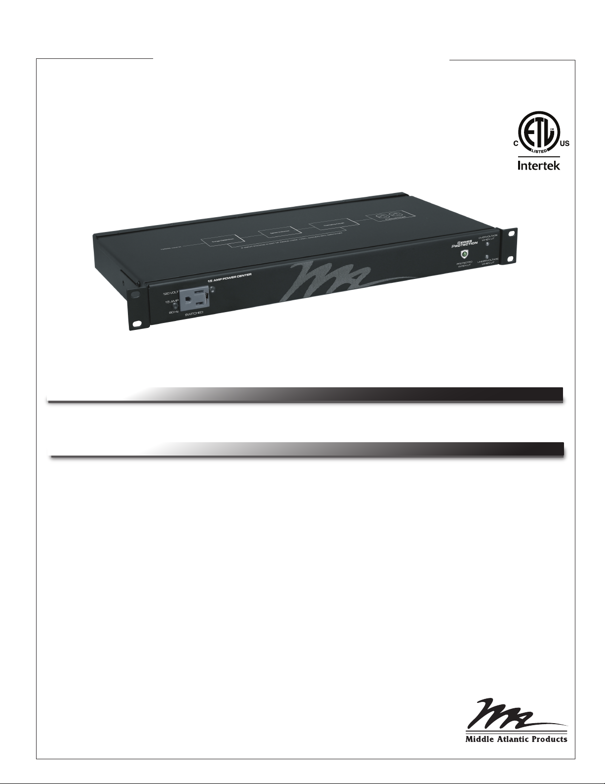
(PD-915R-SP Shown)
THANK YOU
Thank you for purchasing this Series Protection™ Product.
PRODUCT FEATURES
- Non-sacrificial surge technology protects equipment without compromising system ground.
- No MOVs or other degrading parts
- Voltage protection automatically powers outlets off during over/under voltage conditions and
automatically restores power when voltage returns to normal
- Thermal circuit breaker overload protection
- Advanced EMI / RFI filtering
- Automatic self-test circuit with front panel indicators
- Universal mounting brackets
I-00537 Rev D
Page 2

Page 3
IMPORTANT SAFETY INSTRUCTIONS
READ AND SAVE THESE INSTRUCTIONS!
CONSERVER CES INSTRUCTIONS!
• Contains switched receptacle(s). To reduce risk of shock , disconnect the
device from the power source before servicing any connected
equipment
Contient de(s) receptacle(s) commuté(s). Pour réduire les risques
d'électrocution, débranchez l'appareil de la source d'alimentation
avant l'entretien de tout équipement connecté
• Do not overload the wall outlet where this device is being connected. Do not
overload this device. Ensure the total load to this device does not exceed that
which is listed in the specifications section of this manual
Ne surchargez pas le réceptacle de mur ou le circuit qui fournit l'énergie à ce
appareil. Ne pas surcharger cette appareil. S'assurer que la charge totale à cet
appareil ne dépasse pas celle qui est répertoriée dans la section des
spécifictions de ce manuel
• Ensure this device is connected to a properly grounded AC power source.
Ensure the device is plugged into a source providing the required 120V. Do not
use a plug adapter that defeats the ground pin of the AC plug
Assurez-vous cet appareil est connecté à une source d'alimentation C/A avec
mise à la terre. Assurez-vous cet appareil est branché sur une source
d’alimentation fournissant les nécessaires 120V. Ne pas utiliser un adaptateur
qui contrecarre la broche de terre de la prise du cordon d’alimentation
• There are no user-serviceable components within this device. Removal of the
cover from this device may present a shock hazard, and void the warranty
Il n'ya pas de composants réparables par l'utilisateur au sein de cet appareil.
Retrait de la couverture de cet appareil peut présenter un danger
d'électrocution et annuler la garantie
DANGER HAZARDOUS VOLTAGE/DANGER HAUTE
TENSION
The lightning flash with the arrowhead symbol, within an
equilateral triangle is intended to alert the user to the
presence of uninsulated dangerous voltage within the
product’s enclosure that may be of sufficient magnitude to
constitute a risk of electric shock to persons.
L'éclair avec le symbole de flèche dans un triangle
équilatéral est destiné à alerter l'utilisateur de la présence
d'une tension dangereuse non isolée dans l'enceinte du
produit qui peut être d'une ampleur suffisante pour constituer
un risque de choc électrique pour les personnes.
CAUTION/ATTENTION
The exclamation point within an equilateral triangle is
intended to alert the user to the presence of important
operating and maintenance (servicing) instructions in the
literature accompanying the appliance.
Le point d'exclamation dans un triangle équilatéral est
destiné à alerter l'utilisateur de la présence d'importants
instructions d’opération et de maintenance (entretien) dans la
documentation accompagnant l'appareil.
• To be used indoors in a dry location only
Pour être utilisé en intérieur dans un endroit sec seulement
• Do not operate with a damaged cord or plug
Ne pas faire fonctionner avec un cordon ou une prise endommagée
• Clean only with dry cloth
Nettoyer avec un chiffon sec seulement
WARNING! Failure to read, understand and follow the following information can result in serious personal injury, damage to the
!
equipment or voiding of the warranty.
WARNING! This equipment is not intended to be used in conjunction with life support systems or life saving devices.
!
WARNING! Do not install a 3-to-2 prong adapter or defeat the grounding capability of the three-wire grounded-type AC plug.
!
WARNING! Do not place power cord in high traffic areas (e.g. hallways, doorways, etc) or where placement would create a trip hazard.
!
!
CAUTION - Do not install this device near high heat sources such as stoves, radiators, wall heaters or inside any enclosed space
without adequate ventilation.
CAUTION - Ungrounded power systems are inherently unstable and can produce excessively high line-to-ground voltages during
!
certain fault conditions. During these fault conditions any electrical equipment, including an SPD, may be subjected to voltages
which exceed their designed ratings. This information is being provided to the user so that an informed decision can be made before
installing any electrical equipment on an ungrounded power system.
For all models except PD-HW15-SP:
CAUTION: Do not install this device if there is not at least 10 meters (30 feet) or more of wire between the electrical outlet and the
!
electrical service panel.
Page 3
Page 4

REGULATORY COMPLIANCE
The product meets the requirements of the following standards:
• UL 1283 and UL 1449, 3rd Ed.
• CSA C22.2 No.8-M1986, R2000
Federal Communications Commission (FCC) Compliance Statement
NOTE: This equipment has been tested and found to comply with the limits for a Class B digital device,
pursuant to Part 15 of the FCC Rules. These limits are designed to provide reasonable protection
against harmful interference in a residential installation. This equipment generates uses and can radiate
radio frequency energy and, if not installed and used in accordance with the instructions, may cause
harmful interference to radio communications. However, there is no guarantee that interference will not
occur in a particular installation. If this equipment does cause harmful interference to radio or television
reception, which can be determined by turning the equipment off and on, the user is encouraged to try to
correct the interference by one or more of the following measures:
-- Reorient or relocate the receiving antenna.
-- Increase the separation between the equipment and receiver.
-- Connect the equipment into an outlet on a circuit different from that to which the receiver is connected.
-- Consult the dealer or an experienced radio/TV technician for help.
Industry Canada (IC) Compliance Statement
This Class B digital apparatus complies with Canadian ICES-003.
Cet appareil numérique de la classe B est conforme à la norme NMB-003 du Canada.
Page 4
Page 5

TABLE OF CONTENTS
Product Features Page 1
Before You Begin Page 3
Important Safety Instructions Page 3
Regulatory Compliance Page 4
Introduction Page 5
Connections, Controls and Indicators Page 6
Models Page 7
Installation Pages 8 - 9
Specifications Page 10
Warranty Page 11
INTRODUCTION
Available in 15A or 20A models, and in rackmount, half-rack or hard-wired form factors (15A only),
Series Protection™ products provide instantaneous protection of AV systems against damaging
surges without contaminating system ground, while also providing automatic recovery after both
over- and under-voltage events.
All models are 100% MOV-free and utilize all non-degrading and no sacrificial components.
Page 5
Page 6
CONNECTIONS, CONTROLS AND INDICATORS
PD-915R-SP
7
PD-920R-SP
1
4
5
POWER
ON
6
ON
OFF
2
3
PD-915R-SP
1
RESET
5
POWER
6
ON
OFF
4
2
3
3
OVERV OLTAGE
WHEN LIT
UNDERVO LTAGE
WHEN LIT
4
PD-415R-SP
PD-920R-SP
3
OVERV OLTAGE
WHEN LIT
UNDERVO LTAGE
WHEN LIT
4
RESET
8
5
POWER
ON
OFF
2
20 AMP POWER CENTER
PROTECTED
WHEN LIT
6
7
PD-420R-SP
2
PROTECTED
WHEN LIT
7
15 AMP POWER CENTER
8
5
POWER
ON
OFF
6
120V - TOTAL 15A - 60Hz
SWITCHED
7
PD-415R-SP
3
7
Input Output
PD-HW15-SP
Junction Box
120VAC
60Hz 15A
2
9
PD-HW15-SP
10
Page 6
Page 7
CONNECTIONS, CONTROLS AND INDICATORS (CONTINUED)
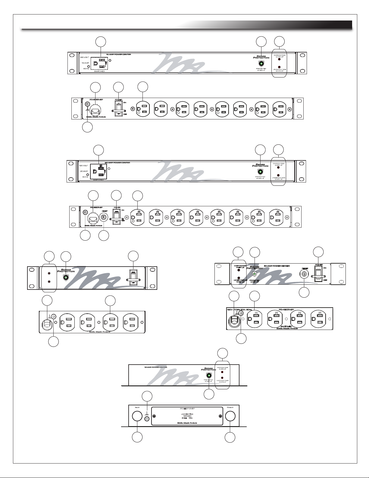
DESCRIPTION
FRONT CONVENIENCE POWER OUTLET (REFER TO MODELS FOR AMPERAGE RATING)
1
2
POWER LED: Illuminates green to indicate operational status.
OVERVOLTAGE / UNDERVOLTAGE LEDS Overvoltage LED indicates red when overvoltage
3
condition is present. Undervoltage LED indicates red when undervoltage condition is present.
9FT POWER CORD (EXCEPT PD-HW15-SP)
4
POWER SWITCH (INTEGRATED CIRCUIT BREAKER INCLUDED ON PD-915R-SP and
5
PD-415R-SP ONLY)
6
REAR POWER OUTLET (REFER TO MODELS FOR AMPERAGE RATING)
7
SUPPLEMENTAL GROUNDING AND BONDING STUD
8
RESETABLE 20 AMP CIRCUIT BREAKER (PD-420R-SP and PD-920R-SP ONLY)
9
ELECTRICAL FITTING OPENING INPUT (PD-HW15-SP ONLY)
10
ELECTRICAL FITTING OPENING OUTPUT (PD-HW15-SP ONLY)
MODELS
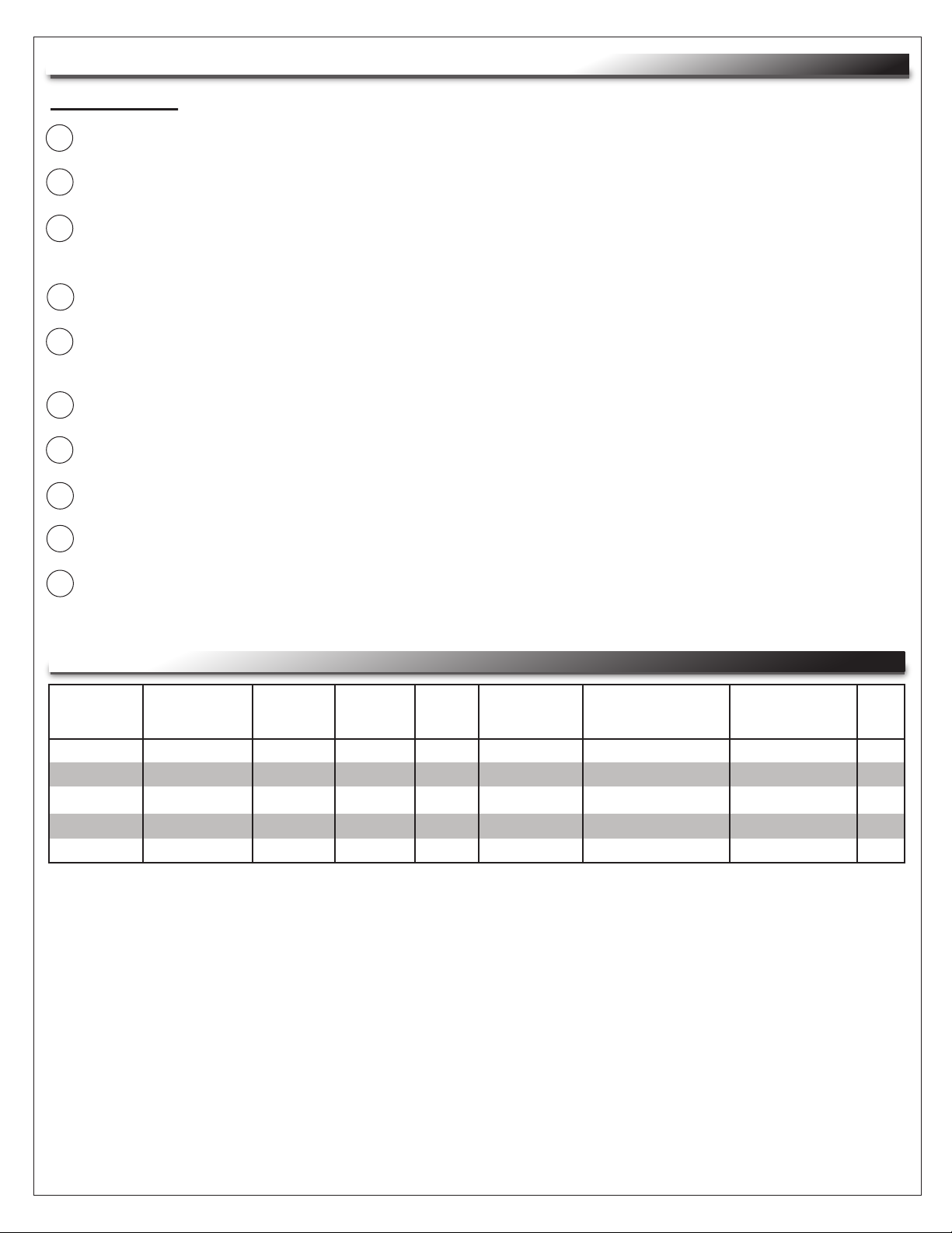
MODEL
NUMBER
PD-915R-SP
PD-920R-SP
PD-415R-SP
PD-420R-SP
PD-HW15-SP
CHASSIS OUTLETS
RACKMOUNT
RACKMOUNT
HALF RACK
HALF-RACK
STAND ALONE
INPUT
9ft CORD
9ft CORD
9ft CORD
9ft CORD
INT. J-BOX
9
9
4
4
INT. J-BOX
RATING
15A
20A
15A
20A
15A
OVER/UNDER
VAC
PROTECTION
YES
YES
YES
YES
YES
SURGE
MODE
DIFFERENTIAL (L-N)
DIFFERENTIAL (L-N)
DIFFERENTIAL (L-N)
DIFFERENTIAL (L-N)
DIFFERENTIAL (L-N)
SUPPLEMENTAL
OVERCURRENT
PROTECTION
YES
YES
YES
YES
NO
SPD
TYPE
3
3
3
3
2
Page 7
Page 8
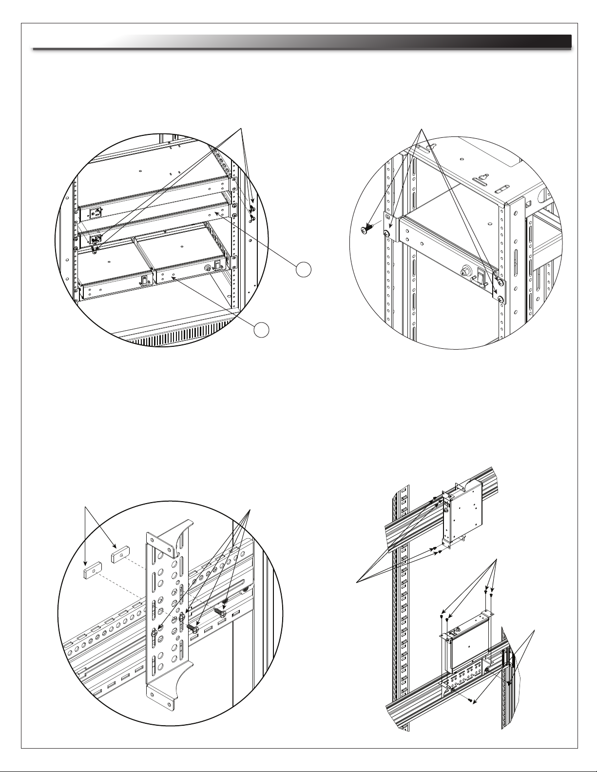
INSTALLATION
NOTE: Any attachment-plug receptacles in the vicinity of Series Protection™ products are to be of a
grounding type, and ground conductors serving these receptacles are to be connected to earth
ground at the service entrance or other acceptable building earth ground.
Rack Mount Screws (4)
1
2
1) PD-915R-SP / PD-920R-SP MOUNTED IN A STANDARD 19” RACK
2) PD-415R-SP / PD-420R-SP MOUNTED SIDE-BY-SIDE WITH RACK EARS
REMOVED
NOTE: RACK EAR SCREWS MUST BE RE-INSTALLED IN CHASSIS AFTER
RACK EAR REMOVAL
Rack Mount Screws (4)
PD-415R-SP / PD-420R-SP
MOUNTED IN A HALF RACK
10-32 Sliding Nut (2)
Rack Mount Screws (4)
Rack Mount
Screws (4)
Rack Mount
Screws (4)
Rack Mount
Screws (2)
PD-415R-SP / PD-420R-SP
BRACKET MOUNTING
Page 8
Page 9
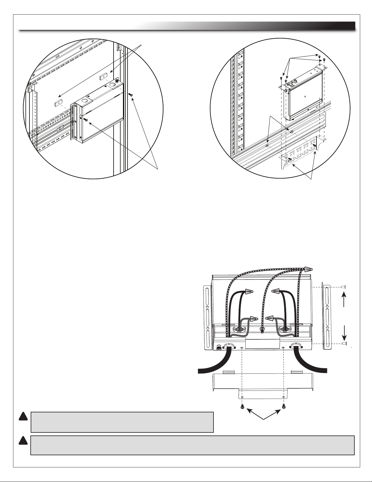
INSTALLATION (CONTINUED)
Rack Mount Screws (4)
Threaded
Clips (2)
Must be installed by Qualified Electrical Personnel (Licensed Electrical Contractor)
PD-HW15-SP MOUNTED
IN A STANDARD 19” RACK
10-32 Sliding Nuts (2)
Rack Mount Screws (2)
Rack Mount Screws (2)
PD-415R-SP / PD-420R-SP MOUNTED
TO VISIONFRAME™ MONITOR WALL
PD-HW15-SP COVER REMOVAL AND WIRING
1) Remove two (2) cover screws to access wiring. (FIGURE A)
2) Wire the device though electrical fitting openings as shown. (FIGURE A)
• The input (line) of the PD-HW15-SP must be
hardwired directly to an electrical
distribution panel.
BLACK
• The output (load) of the PD-HW15-SP must be
hardwired directly to an electrical junction
WHITE
box or other AHJ-approved connection.
• Cord and plug type connections to the
PD-HW15-SP are explicitly prohibited.
• Ground conductor must be green with
or without yellow stripe(s) and must be
connected to earth ground at the
service equipment or other
INPUT
(LINE)
acceptable building earth ground.
GROUND WIRES
BLACK
WHITE
Bracket
Mounting
Screws
OUTPUT
(LOAD)
3) Replace cover prior to restoring power.
!
!
CAUTION: Conductors used to connect device should
be as short as possible.
Cover Screws (2)
CAUTION: To be installed with a minimum of 14 AWG (2.5 mm2) wire that complies
FIGURE A
with local electrical codes.
Page 9
Page 10
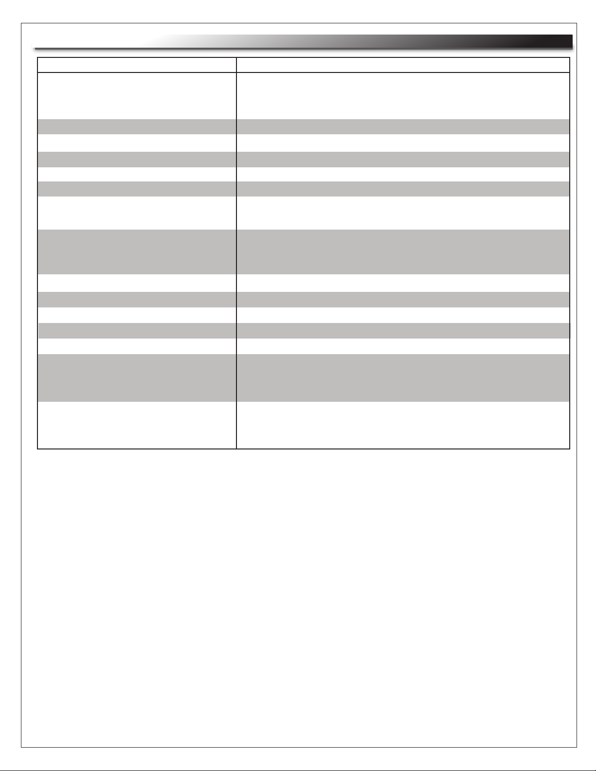
SPECIFICATIONS
SPECIFICATION
Load rating @ 120 VAC
PD-915-SP, PD-415R-SP, PD-HW15-SP
PD-920-SP, PD-420R-SP
Operating Voltage Range
Power Requirement (no load)
Maximum Ambient Temperature
Voltage Protection Rating
Clamping Voltage
UL 1449 Adjunct Classification Test Results
DETAILS
15 Amp RMS load @ 120 VAC
20 Amp RMS load @ 120 VAC
90-150V
5 watts
35ºC
330V
186V for a nominal line voltage of 132V
1000 surges, 6000 volts, 3000 amps, B3 pulse.
Measured suppressed voltage: 170V, no failures
EMI/RFI Filter
Normal Mode (50-ohm load)
Common Mode (50-ohm load)
SCCR Rating
Maximum Applied Surge Voltage
Maximum Applied Surge Current
Maximum Applied Surge Energy
Endurance (662.41-1991 Category B3 pulses)
40 dB @ 100 kHz; 50 dB @ 300 kHz; 50 dB @ 3 MHz; 50 dB @ 30 MHz
18 dB @ 300 kHz; 30 dB @ 1 MHz; 50 dB @ 5 MHz; 50 dB @ 20 MHz
5000 amps
6000 volts
Unlimited, due to current limiting
Unlimited, due to current limiting
1
2
2
2
3 kV > 10,000; 6kV > 1000
Overvoltage Threshold (Outlets only)
Upper Limit Cutoff
Upper Limit Restore
135V RMS
126V RMS
3
3
Undervoltage Threshold (Outlets only)
Lower Limit Cutoff
Lower Limit Restore
100V RMS
105V RMS
3
3
1
SCCR rating of 5000 amps when protected by a circuit breaker rated: 15 Amps and 120 Volts
2
1.2 x 50 µs pulse, industry standard combination wave surge, as per IEEE C62.41
3
All measurements taken with 0.8 power factor load
Page 10
Page 11

WARRANTY
Middle Atlantic Products (the "Company") warrants the Series Protection Power Distribution with
Series Circuit Protection to be free from defects in material or workmanship under normal use and
conditions for a period of (12) twelve years from date of shipment by the Company.
The Company's entire liability to the purchaser, and the purchaser's (or any other party's) sole and
exclusive remedy, under this warranty shall be limited, at the Company's option, to either (a) return of
and refund of the price paid for, or (b) repair or replacement at the Company's factory of the products
purchased, or any part or parts thereof, which the Company has determined to be defective after
inspection thereof at the Company's factory.
This warranty does not cover damage due to acts of God, accident, misuse, abuse or negligence by
parties other than the Company, or any modification or alteration of the products. In addition, this
warranty does not cover damage due to improper handling, assembly, installation or maintenance.
THIS WARRANTY IS IN LIEU OF ALL OTHER WARRANTIES OF ANY KIND, EITHER EXPRESSED OR
IMPLIED, INCLUDING, BUT NOT LIMITED TO, IMPLIED WARRANTIES OF MERCHANTABILITY AND
FITNESS FOR A PARTICULAR PURPOSE.
TO THE MAXIMUM EXTENT PERMITTED BY APPLICABLE LAW, IN NO EVENT SHALL THE COMPANY
BE LIABLE FOR ANY SPECIAL, INCIDENTAL, INDIRECT, OR CONSEQUENTIAL DAMAGES
WHATSOEVER (INCLUDING, WITHOUT LIMITATION, DAMAGES FOR LOSS OF BUSINESS PROFITS,
BUSINESS INTERRUPTION OR ANY OTHER PECUNIARY LOSS) ARISING OUT OF THE USE OF THE
PRODUCTS PURCHASED, EVEN IF THE COMPANY HAS BEEN ADVISED OF THE POSSIBILITY OF
SUCH DAMAGES. THE COMPANY'S LIABILITY TO THE PURCHASER (OR ANY OTHER PARTY)
HEREUNDER, IF ANY, SHALL IN NO EVENT EXCEED THE PURCHASE PRICE OF THE PRODUCTS
PAID TO THE COMPANY.
Corporate Headquarters
Corporate Voice 973-839-1011 - Fax 973-839-1976
International Voice +1 973-839-8821 - Fax +1 973-839-4982
middleatlantic.com - [email protected]
Middle Atlantic Canada
Voice 613-836-2501 - Fax 613-836-2690
middleatlantic.ca - [email protected]
Factory Distribution
USA: NJ - CA - IL Canada: ON - BC
At Middle Atlantic Products we are always listening. Your comments are welcome.
Middle Atlantic Products is an ISO 9001 and ISO 14001 Registered Company.
Page 11
Page 12

 Loading...