

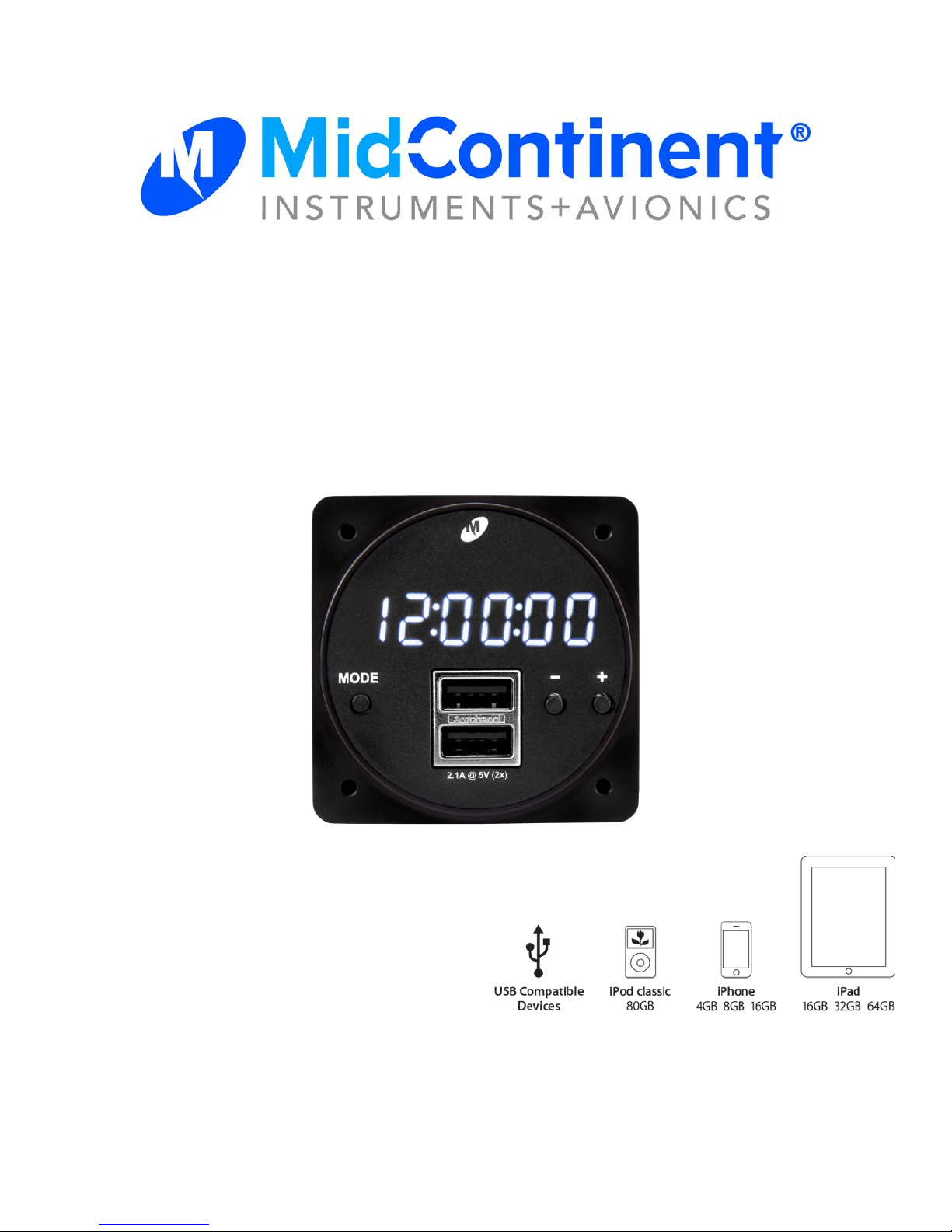
Installation Manual and Operating Instructions
MD93 Series
Digital Clock/USB Charger
Mid-Continent Instruments and Avionics
Mid-Continent Instrument Co., Inc.
dba Mid-Continent Instruments and Avionics
9400 E. 34th Street N.
Wichita, KS 67 22 6 USA Manual Number 9018205
PH (316) 630-0101 FX (316) 63 0-0723 Revision A, July 15, 2014

FOREWORD
This manual provides information intended for use by persons who, in accordance with current
regulatory requirements, are qualified to install this equipment. If further information is required,
please contact:
Mid-Continent Instruments and Avionics
Attn: Customer Service Dept.
9400 E. 34th Str eet N.
Wichita, KS 67 22 6 U SA
PH (316) 630-0101
FX (316) 63 0-0723
www.mcico.com
We welcome your comments concerning this manual. Although every effort has been made to
keep it free of errors, some may occur. When reporting a specific problem, please describe it
briefly and include the manual part number, the paragraph/figure/table reference and the page
number. Send your comm e nts to:
Mid-Continent Instruments and Avionics
Attn: Technical Pu bl i c ati o ns
9400 E. 34th Str eet N.
Wichita, KS 67 22 6 U SA
PH (316) 630-0101
FX (316) 63 0-0723
ks.customerservice@mcico.com
All products produced by Mid-Continent Instrument Co., Inc., including those identified as MidContinent Instruments and Avionics or True Blue Power, are designed and manufactured in
Wichita, KS, USA .
© Copyright 2014
Mid-Continent Instrument Co., Inc.

ECO
Revision
Date
Detail
A 07/15/2014
Initial release.
REVISION HISTORY

TABLE OF CONTENTS
SECTION 1 GENERAL DESCRIPTION 6
1.1 INTRODUCTION 6
1.2 PHYSICAL ATT RIBU TES 6
1.3 UNIT ARCHITECTURE 7
1.4 TECHNICAL SPECIFICATIONS 7
1.4.1 ELECTRICAL ATTRIBUTES 7
1.4.2 PHYSICAL ATTR IBUT ES 7
SECTION 2 PRE-INSTALLATION 8
2.1 COOLING 8
2.2 EQUIPMENT LOCATION 8
2.3 ROUTING OF CABLES 8
SECTION 3 INSTALLATION 9
3.1 GENERAL 9
3.2 PRE-INSTALLATION INSPECTION 9
3.3 PARTS 9
3.3.1 INCLUDED PARTS 9
3.3.2 OPTIONAL AVAILABLE PARTS 9
3.3.3 INSTALLER SUPPLIED PARTS 9
3.4 CABLE HARNESS 10
3.4.1 WIRE GAUGE SELECTION 10
3.4.2 PIN ASSIGNMENT INFORMATION 10
3.4.3 HARNESS VERIF ICATION 10
3.5 INSTALLATION 11

3.5.1 DIMMING FUNCTIONS 11
SECTION 4 USB CHARGER OPERATION 12
4.1 DESCRIPTION 12
4.2 OPERATIONAL MODES 12
4.3 PROTECTIVE FEATURES 12
4.3.1 SHORT CIRCUIT PROTECTION 12
4.3.2 OVER-CURRENT PROTECTION 12
4.3.3 LOW INPUT VOLTAGE SHUTDOWN 12
4.3.4 OVER-TEMPERATURE 12
SECTION 5 CLOCK / CHRONOMET ER OPERATION 13
5.1 DESCRIPTION 13
5.2 CONSTRUCTION 13
5.3 OPERATIONAL MODES 13
5.3.1 LOCAL TIME OPERATION / SETTING 14
5.3.2 UNIVERSAL TIME OPERAT ION / SETTING 15
5.3.3 FLIGHT TIMER 16
5.3.4 ELAPSED TIMER 17
5.3.5 DISPLAY TEST MODE 18
SECTION 6 CONFORMANCE 18
6.1 INSTRUCTIONS FOR CONTINUED AIR WORTHINESS 18

SECTION 1 GENERAL DESCRIPT ION
1.1 INTRODUCTION
The MD93 series, part number 6430093-( ) is a digital clock / chr onom eter with a Dedicated Charging
Port (DCP) for USB dev ic es (specifically 2 USB chargi ng ports) f itting into a standard 2 ¼” avionics panel
cutout. Power is drawn from the aircraft main bus to light a white, six digit, and seven segment LED clock.
The clock can display sev er al diff er ent modes: local time, universal time, flight timer and elapsed timer
functions. The MD93 LEDs are day light readable and can be dimmed duri ng r educ ed light conditions by
external voltage stimulus. W hen the external voltage is not present the c lock LED and annunciations are
dimmed by means of an internal phot oc ell. The MD93 clock has an internal batt er y to m aintain clock and
flight timer functions when the aircraft is not in use.
The Dual USB Charging Port i s designed as a DCP (Dedicated Charging P ort) to industry-standard
protocol per the USB Battery Char ging 1.2 Compliance Plan. Early-gener ation or smaller consumer
electronics ty pic ally accept one (1.0) amp during char ging. However, newer electr onic s, such as tablets
and larger devices can accept , and in some cases, require up to 2.1 amps to charge and operat e. As a
high power DCP, the MD93 can provide up to 2.1 amps to charge any USB device, including the higher
demand products. Unlike most dual USB chargers which provi de one ( 1.0) amp on one port and 2.1 amps
on the second port, t he MD93 can prov ide 2.1 amps to both ports simult aneousl y. Wit h feat ur es li k e short
circuit protec tion, over-current protection, low voltage shut-down and temperature monitoring, it can
handle abnormal conditions safely .
1.2 P HY SIC AL AT T R I B UTE S
The cutout i s a single, integrated component cont ained in a metal enclosure, fitting into a standard 2 ¼”
avionics instrument panel cutout. A 4-pin connector on the rear of t he unit is used for power input,
external dimmi ng c ontrol and flight timer operation. The front of the unit houses dual, USB Standard-A
receptacles. Thr ee butt ons on the front of the unit are used for changing modes of operation between
clocks and timers as well as setting/resetti ng cl ocks and timer s. Refer to Figure 1 below for unit
dimensions.
Figure 1
MD93 Outline Drawing
Mid-Continent Instrum ents and Avionics
Revision A, July 10, 2014 Manual Number 9018205
6

Input Voltage:
10 – 32 VDC
Input Power:
31 watts m ax; 2.2 amps @ 14 VDC / 1.1 amps @ 28 VDC
Output Voltage:
5 VDC ± 0.25 VDC per USB port
Output Power:
2.1 amps max per USB port
Efficiency:
≈ 85% nominal
Clock Accuracy:
Less than ± 1.0 seconds per 24 hour period
Weight:
0.25 pounds
Dimensions :
(not including connec tor)
2.385 inches wide x 2.385 inches high x 1.15 inches deep
Charging Ports Ty pe:
USB Standard-A
Clock Digits:
0.360” H x 0.138” W
Connector Kit:
MCIA P/N 9018178
Mounting:
Rear Panel Mount
1.3 UNIT ARCHITECT URE
The unit is comprised of two primary building blocks, a USB charger and digital clock. 10-32 VDC input
power is regulated, 5 VDC via DC-DC converter used to power the USB charger and all
clock/chronometer functions. A charging port controller m anages power out put for the dual USB charger
port. An internal batt er y mai ntains clock functions when air c r aft power is removed.
1.4 TECHNICAL SPECIFICATIONS
1.4.1 Electrical Attr ibutes
1.4.2 Physical Attributes
Tabl e 1
Electrical Attri bu t es
Table 2
Physical Attribu t es
Mid-Continent Instrum ents and Avionics
Revision A, July 10, 2014 Manual Number 9018205
7

SECTION 2 PRE-INSTALLATION
2.1 COOLING
The MD93 will become warm when in use; however no external cooling is required. This is normal and
within operational parameters. No special m ounting considerations are requi r ed, although mounting to a
metal surface can hel p dissipat e any heat generated and extend the life of t he pr oduc t.
2.2 EQUIPMENT LOCATION
The MD93 Digital Cloc k / Dual USB Charging Port is designed for a circular rear panel mount
configuration, allowing for installation in a cockpit or cabin. Clearance should be provided for the input
mating connector which may require an additional inch of clearance bey ond the rear of the unit.
2.3 ROUTING OF CABLES
Avoid sharp bends in cabli ng and r outing near aircraft control cables. Avoid close proximity and contact
with aircraft str uctur es, av ionics equipment or other obstr uc tions that could chafe wir es during flight and
cause undesirable effects.
Mid-Continent Instrum ents and Avionics
Revision A, July 10, 2014 Manual Number 9018205
8

SECTION 3 INSTALLATION
3.1 GENERAL
This section contains interconnect diagrams, mounting dimensions and other information pertaining to the
install ation of the MD93 Digital Clock / Dual USB Charging Port. Aft er i nstallation of cabling and bef or e
install ation of the equipment, ensure that power and ground are applied to the proper pins specified in
Section 3.4.2, Pin Assignment Inf ormation.
3.2 PRE-INSTALLATION INSPECTION
When unpacking thi s equi pm ent, m ak e a vi sual i nspecti on for evidence of any damage that may have
occurred during shi pm ent.
3.3 PARTS
3.3.1 Included Parts
The following parts are included:
• Digital Cloc k / Dual USB Charging P or t MCIA P/N 6420093-( )
• Installation Manual MCIA P/N 9018205
• Installation Kit MCIA P/N 9018178
o M ating Connector, 4-pin
o P ins (6) (4 required, 2 spares)
o Screws (5), #6-32 x 3/8” Flat Head (4 required, 1 spare)
3.3.2 Optional Available Parts
No additional par ts or components are available.
3.3.3 Installer Supp lied Parts
• Cable Harness Wire, See Section 3.4.1 for specif ic ations
• Circuit Breaker Recommendation 2.5 amp (1.5 amp may be suffi ci ent f or 28V airc r aft)
(as needed per system requir em ents)
Mid-Continent Instrum ents and Avionics
Revision A, July 10, 2014 Manual Number 9018205
9

Wire Gauge
Wire Length
20 AWG stranded wire
>35 ft.
22 AWG stranded wire
>14 ft.
24 AWG stranded wire
<14 ft.
Pin Number
Signal
1
Aircraft Power
2
Ground
3
Aircraft Lighting Bus
4
Flight Timer Input
3.4 CABLE HAR NESS
Construct the cable harness following the instr uc tions outlined below and per Tables 3 and 4. Refer to
Section 2: Pre-Installation Considerations for r outing precautions.
3.4.1 Wire Gauge Selection
Use of PTFE, ETFE, TFE, Teflon or Tefzel insulated wire is recommended f or ai rcr af t use. The wire
harness should util iz e 20-24 AWG stranded wir e. Refer to Table 3 below for suggested minimum wire size.
Table 3
Wire Gauge and Length
Note: Pins should be crimped using M olex Hand Crimp Tool 63819-0000 (prefer r ed) , 63811-2800
(obsolete) or 11-01-0200 (obsolete). See the Molex Hand Crimp Tool User Manual for crimp procedur es.
3.4.2 Pin Assignment Information
See Table 4 for pinout definition and Figure 2 for pin locations.
Table 4 Figure 2
Power Input Connector Pinout MD93 Rear View
3.4.3 Harness Verification
*** WARNING ***
Failure to install aircraft power and ground wires in t he proper mating connector locati ons could
damage the unit.
Once the cable harness is prepared, pr ior to connecti ng the MD93, activate the aircraft power bus
and use a multimeter to verify that aircraft power and ground are supplied with appropriate v oltage on
the proper pins within the mating harness.
The MD93 must not be installed with input t erminals reversed as this coul d dam age the unit. Verify
the correct polari ty of any harness or equipment prior to connecting to the MD93.
Mid-Continent Instrum ents and Avionics
Revision A, July 10, 2014 Manual Number 9018205
10

3.5 INSTALLATION
The MD93 is rear mounted usi ng a standar d 2 ¼” panel cutout. Prepare t he panel c utout as shown in
Figure 3 below. Prior to installing the unit, the di spl ay dimming should be adjusted accordi ng to section
3.5.1, Dimming Functions. Mount the MD93 wit h #6-32 flat head screws (provided with installation ki t).
NOTE: The maximum screw length used to mount the unit is 9/32” (0. 280” ) + panel thickness.
*** WARNING ***
Using screws longer than the recommended maximum length may damage the MD93 unit!
Figure 3
Rear Panel Mount Installation
3.5.1 Dimming Functions
The MD93 will accept a power input from the aircraft bus between 10 to 32 volts on pin 1. The
unit brightness can be manually controll ed by supplying a lighting input volt age on pin 3. T he
lighting input voltage will be compared to the power input and will control the lighting when it is
between 10-100% of the power input . A voltage equal to the aircraft bus v oltage (100%)
corresponds to maximum brightness. If the lighting voltage is less than 10% of the power input
voltage, dimming will be automatically contr olled by the ambient light sensed by the phot oc ell built
into the unit.
To adjust the brightness range of the clock for optimal daytime and night-time viewing, as well as
balance amongst other panel instruments, use the two adjustments on the rear of the unit as
shown in Figure 2. Set the input voltage/lighting bus to m aximum and turn the “Aircraft dim adjust”
screw to raise or lower the bri ghtness. Next, turn the input voltage/lighting bus off in dar k
conditions and tur n the “Photocell dim adjust” screw to raise or lower the brightness.
NOTE: the adjustment screw has a single 360° r ange of rotation. Exceeding its limi ts past the
stops will damage the unit .
The brightness of the unit can be automatically cont r olled based on ambient light conditi ons using
the internal photocell at all times simply by not installing the lighting input v oltage on pin 3. To
adjust the desired brightness range, follow the “P hotocell dim adjust” method in the previous
paragraph in dark conditions.
Mid-Continent Instrum ents and Avionics
Revision A, July 10, 2014 Manual Number 9018205
11

SECTION 4 USB CHARGER OPERATION
4.1 DESCRIPTION
The MD93 Dual USB Charging Port conv er ts aircraft DC input voltage within the range specified to a 5V
DC output. This output power is appl ied to a dual USB-A connector in accordanc e with the USB
Implementers Forum ’s Dedicated Charging Port Compliance Plan.
4.2 OPERATIONAL MODES
The USB D+ and D- data lines communicate with the USB portable device to tell the device it is a
dedicated charging port (DCP), capab le of a higher current than a standard USB port. Each USB port on
the MD93 can provide up to 2.1 amps (simultaneously) at 5 VDC.
4.3 PROTECTIVE FEATURES
4.3.1 Short Circuit Protection
The MD93 is capable of surviving a short circuit event without permanent damage. The unit enters an
over-c ur r ent condition so that the average c urrent is signif icantly reduced and the device is protected.
4.3.2 Over-Current Protection
The MD93 monitors current draw individually on each port. During an over-current condition the
output is turned off until the over-current condition is remov ed. Once the overcurrent condition is
removed, the unit returns to normal operation.
4.3.3 Low Input Voltage Shutdown
If the input voltage applied to the MD93 drops below 10 VDC the unit will shut down until the applied
voltage ret ur ns to a lev el within operating range.
4.3.4 Over-Temperature
If the tem per ature of the MD93 becomes elevated, the unit communicates with the USB port able
device to reduce the c har ge c urrent output to a 1.0 amp limit. When temperature returns to an
acceptable level the unit automaticall y ret ur ns to a higher charge c ur r ent as required (up to 2.1
amps).
Mid-Continent Instrum ents and Avionics
Revision A, July 10, 2014 Manual Number 9018205
12

LOCAL TIME
‘FLIGHT
’ a nnunciation is display ed. F light timer is display ed (alway s in tenths of
hours – e.g . 5.9 or 258.7).
No a nnunciations for time mode are dis played. Local time is displaye d.
FLIG HT TIMER
ELAPSED TIMER
(STOPWATCH)
UNIVE RSAL TIME
‘TIMER
’ annunciation is displaye d. The ela psed time r is display ed in hour s,
minutes, and s econds.
‘UTC’
annunciation is display ed. Univer sa l time is displaye d (alway s in 24 hour
for mat)
Press MODE
Press MODE
Press MODE
Press MODE
SECTION 5 CLOCK / CHRONOMETER OPERATION
5.1 DESCRIPTION
The clock/chronometer portion of the MD93 has 4 modes of operati on, including local tim e, univer sal
time, flight tim er and elapsed timer. Specific operation instructions are covered in Section 5.3
(Operational M odes).
5.2 CONSTRUCTION
The clock has six di gits that are 0.360” tall and 0.138” wide. Three user interf ace buttons (MODE, , and
+) are utilized to switch bet ween m odes of oper ation, set clock tim e, and manage timer functions for the
MD93. Backlit annunciations on the front bezel are included whi c h indicate current mode of operation.
When aircraft power is removed, the display clock and all annunc iations will be tur ned off . T he M D93
contains a batter y that maintains clock functions (local time, universal time, flight tim er) when airc r aft
power is removed for well ov er ten year s.
5.3 OP ERATIONAL MODES
The MD93 modes of operation f or clock functions are, in order: local time, universal time, flight timer, and
elapsed timer. Note: When the clock is in local time function, there ar e no annunci ations to indicate as
this is the default mode of operation. The mode button (MODE) is used to alternate between four different
operational modes; specific ally , local time > universal time > flight timer > elapsed timer > (and back to)
local time, etc. This is performed by pressing the MODE button. Refer to Figure 5 - Modes of Operation
for changing modes of operation.
Mid-Continent Instrum ents and Avionics
Revision A, July 10, 2014 Manual Number 9018205
Figure 4
Modes of Operation
13

LOCAL TIME D isplay
Time is displayed with hours flashing. Pressing the -/+ buttons
decrements/increments hours.
Current time is displayed. Pressing the -/+ buttons have no function.
HOURS Set
MINUTES Set
12/24 HR Select
Time is displayed with minutes flashing. Pressing the -/+ buttons
decrements/increments minutes. Note: Setting local time minutes also sets
universal time minutes.
Displays current mode, 12 (flashing) or 24 (flashing) in seconds location. ‘Hr’ shown
in minutes location. Pressing either – or + buttons toggles between 12 and 24 hour
modes.
Press & Hold
MODE
for 2 sec
Press MODE
Press MODE
Press MODE
SECONDS Display
Displays current mode: ‘SEC on’ (seconds on) or ‘SECoFF’ (seconds off). Pressing
either – or + buttons toggles between seconds on and off modes. Note: Turning
seconds on/off for local time also changes setting for universal time.
SECONDS Set
Time is displayed with seconds flashing. Pressing either – or + button resets
seconds to zero. Note: Resetting local time seconds also resets universal time
seconds.
Press MODE
Press MODE
5.3.1 Local Time Operation / Setting
When power is applied t o the MD93, t he system defaults to local time mode (there i s no indication
or annunciation showing “LOCAL” time). To set time and preferences (e.g. 12/24 hour, display or
hide seconds) refer to Figure 7. Note: As minutes and seconds can also be set in universal time
mode, it is not necessary to set minutes or seconds when setting local time (refer to universal
time operation/setting). Howev er, if minutes and/or seconds are set for local time, the system will
update the minutes and seconds in universal time as well.
Mid-Continent Instrum ents and Avionics
Revision A, July 10, 2014 Manual Number 9018205
Figure 5
Local Tim e Clock Mode
Figure 6
Setting / C onfiguring Loca l Tim e
14

UNIVERSAL TIME Display
Time is displayed with hours flashing. Pressing the - /+ buttons
decrements/increments hours.
Current universal time is displayed.
‘UTC’
is annunciated. Pressi ng the -/+
buttons have no function.
HOURS Set
MINUTES Set
Time is displayed with minutes flashing. Pressing the -/+ buttons
decreme nts/increme nts minutes. Note: Setti ng universal ti me minute s also se ts
local time minute s.
Press &Hold MODE
fo r 2 se c
Press MODE
Press MODE
SEC ONDS Display
Displays current mode : ‘SEC on’ (seconds on) or ‘SECoFF ’ (seconds off). Pressi ng
either – or + buttons toggles be tween seconds on and off modes. Note: Turni ng
seconds on/off for universal time also changes setting for local time.
SECONDS Set
Time is displayed with seconds flashing. Pressing either – or + button resets
seconds to zero. Note
: Resetti ng universal time seconds also resets local time
seconds.
Press MODE
Press MODE
5.3.2 Un iversal Time Operation / Setting
When operational mode is changed to universal time, UTC will be backlit (refer to Figure 8). To
set UTC time, refer to Figure 9 - Set ting Universal Time. Setting minutes and seconds in UTC
time also sets minutes and seconds for local time.
Mid-Continent Instrum ents and Avionics
Revision A, July 10, 2014 Manual Number 9018205
Figure 7
Universal Time Clock Mode
Setting Universal Time
Figure 8
15

RESETTABLE FLIGHT TIMER
Flight timer is displayed ( in tenths of hours). Flight
timer is enabled if input signal is pulled high or low.
The decimal point w ill blink off for approximately
1/10thof a second every two seconds to indicate that
the flight time r is currently enabled.
RESETTABLE FLIGHT
TIMER
is res et
Press &Hold
MODE for 2 s ec
NON-RESETTABLE FLIGHT
TIMER
The Non-Re settable Flight time r is viewe d by holding
either the – or + button. When the (- or +) button is
released, flight timer displays the resettable flight
timer. The non-resettable flight timer can only be
reset at the factory.
Press & Hold +
or - button
Release + or button
5.3.3 Flight Timer
When operational m ode is changed t o flight timer, FLIGHT will be backlit (refer to Figure 10). In
order for the fli ght timer to be active, a ground or aircraft power signal m ust be suppl ied to pin 4 of
the connector. This can be provided from an event-based relay ( such as engine star t or weighton-wheels). Or it can sim ply be connect ed v ia jumper to the power or ground pins of the unit to
activate on unit power. The decimal point will blink briefly every 2 seconds to indicate that the
flight timer is active. Flight tim e is displayed in hours and tenths of hours up to 99999.9 hours.
The flight timer maintains the accumulated time (but does not run) when power is off.
Two flight tim ers are enabl ed on the MD93. The default flight timer shown (normall y in FLIG HT
mode) is a resettable timer. Pressing and holding either – or + button will display the nonresettable flight timer. Upon releasing the – or + button, the resettable flight timer will be
displayed. For more detailed operation of flight tim er , refer to Figure 11 below.
Figure 9
Flight Tim e r Mode
Mid-Continent Instrum ents and Avionics
Revision A, July 10, 2014 Manual Number 9018205
Figure 10
Flight Tim e r Ope r a tion
16

TIMER RUNNING
TIMER RESETS TO 0:00
AND RESTARTS COUNTING
Press -
Press -
Press +
TIMER RESETS TO 0:00
TIMER STOPPED
Press +
5.3.4 El apsed Timer
When operational m ode is changed t o elapsed timer, TIMER will be backlit (ref er to Figure 12).
The timer counts up to a maximum of 99 hours, 59 minutes, 59 seconds and then starts again at
zero time. Pressing the + button will start and stop the timer. Pressing the – button resets the
timer. If the timer is counting and the – button is pressed, the timer will reset t o z er o and begin
counting immediately. Note: If the timer is active, the user can change modes (e.g. to local time)
and timer will still r em ain active, but only when power is maintained to the clock. For detailed
timer operation, refer to Figure 13.
Figure 11
Elapsed Timer Mode
Figure 12
Elapsed Timer Operation
Mid-Continent Instrum ents and Avionics
Revision A, July 10, 2014 Manual Number 9018205
17

5.3.5 Display Test Mode
To test the MD93 display, press and hold both +/- buttons for 2 seconds. After 2 seconds all cl oc k
digits shall display 8’s (e.g. 88:88:8. 8) and all annunc iators shall be activated until the +/- buttons
are released.
Figure 13
Te st Mod e
SECTION 6 CONFORMANCE
6.1 INSTRUCTIONS FOR CONTI N UE D AIR WORTHINESS
No periodic scheduled maintenance or calibration is necessary for continued airworthiness of the MD93
Digital Cloc k / Dual USB Char ging P or t. If the unit fails to perform to specificati ons, the unit must be
removed and servi c ed by Mid-Conti nent Instruments and Avionics or t heir authorized designee.
Mid-Continent Instrum ents and Avionics
Revision A, July 10, 2014 Manual Number 9018205
18
 Loading...