

Mid-Continent Instrument MD215 Installation Manual And Operating Instructions
Installation Manual and Operating Instructions
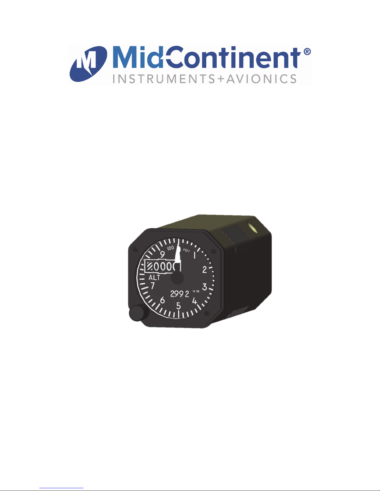
Model MD215 Series
Hybrid Counterdrum Altimeter
Mid-Continent Instrument Co., Inc.
dba Mid-Continent Instruments and Avionics
9400 E. 34th Street N.
Wichita, KS 67226 Manual Number 9018501
ph (800) 821-1212 fx (316) 630-0723 Revision C, October 11, 2017
®

FOREWORD
This manual provides information intended for use by persons who, in accordance with current regulatory
requirements, are qualified to install this equipment. If further information is required, please contact:
Mid-Continent Instruments and Avionics
Attn: Customer Service Dept.
9400 E. 34th Street N.
Wichita, KS 67226 USA
PH (316) 630-0101
FX (316) 630-0723
www.mcico.com
We welcome your comments concerning this manual. Although every effort has been made to keep it free
of errors, some may occur. When reporting a specific problem, please describe it briefly and include the
manual part number, the paragraph/figure/table reference and the page number. Send your comments to:
Mid-Continent Instruments and Avionics
Attn: Technical Publications
9400 E. 34th Street N.
Wichita, KS 67226 USA
PH (316) 630-0101
FX (316) 630-0723
ks.customerservice@mcico.com
All products produced by Mid-Continent Instrument Co., Inc., including those identified as Mid-Continent
Instruments and Avionics or True Blue Power, are designed and manufactured in Wichita, KS, USA.
Manual Number 9018501
© Copyright 2016
Mid-Continent Instrument Co., Inc.
2 Revision C, October 11, 2017

REVISION HISTORY
Revision Date Approved Detail
A 10/30/2015 BAW Initial Release.
B 01/19/2016 BAW Updates for TSO application.
C 10/11/2017 MKN Updated Figure 3.1 with notch.
Manual Number 9018501
3 Revision C, October 11, 2017
TABLE OF CONTENTS
SECTION 1 GENERAL DESCRIPTION .................................................................................. 6
1.1Introduction ...................................................................................................................................... 6
1.2Technical specifications ................................................................................................................... 7
Electrical Attributes ............................................................................................................... 7
Physical Attributes ................................................................................................................. 7
Qualifications ......................................................................................................................... 7
ARINC data labels ................................................................................................................. 8
Gillham Code (Encoding Altimeter output) ............................................................................ 9
SECTION 2 PRE-INSTALLATION ......................................................................................... 10
2.1General Information ....................................................................................................................... 10
2.2Unpacking and inspecting equipment ............................................................................................ 10
2.3Equipment Location ....................................................................................................................... 10
2.4Cable Harness ............................................................................................................................... 10
Wire Gauge Selection ......................................................................................................... 11
Cable Harness Assembly .................................................................................................... 11
2.5Limitations ...................................................................................................................................... 13
SECTION 3 INSTALLATION ................................................................................................. 14
3.1General .......................................................................................................................................... 14
3.2mounting ........................................................................................................................................ 14
Rear Mount Installation ....................................................................................................... 15
Front Mount Installation ....................................................................................................... 16
3.3installation completion .................................................................................................................... 16
SECTION 4 OPERATION ...................................................................................................... 17
4.1Description ..................................................................................................................................... 17
4.2User Interface ................................................................................................................................. 17
Altitude Display and Units ................................................................................................... 18
Pointer ................................................................................................................................. 18
Baro Setting and Units ........................................................................................................ 18
Push-button Rotary Knob (Flight Mode) ............................................................................. 18
Push-button Rotary Knob (Configuration Mode) ................................................................. 19
INOP Flag ............................................................................................................................ 19
Annunciations (Flight Mode) ............................................................................................... 19
4.3Modes of Operation ........................................................................................................................ 19
Flight Mode .......................................................................................................................... 19
Manual Number 9018501
4 Revision C, October 11, 2017
Emergency Mode (for battery-installed units only) .............................................................. 20
Configuration Mode ............................................................................................................. 22
SECTION 5 CONFORMANCE .............................................................................................. 24
5.1Instructions for Continued Air-Worthiness ..................................................................................... 24
Pressure System and Altimeter Verification ........................................................................ 24
Maintenance ........................................................................................................................ 24
Firmware Updates ............................................................................................................... 24
Storage Information (for battery-installed units only) .......................................................... 24
Battery Maintenance and End of Life (for battery-installed units only) ............................... 24
Battery Disposal (for battery-installed units only) ................................................................ 25
Shipping (for battery-installed units only) ............................................................................ 25
5.2ENVIRONMENTAL QUALIFICATION STATEMENT .................................................................... 26
Manual Number 9018501
5 Revision C, October 11, 2017

SECTION 1 GENERAL DESCRIPTION
1.1 INTRODUCTION
The model MD215-( ) series two-inch Electric Hybrid Counterdrum Altimeter is a pressure actuated,
encoding, sensitive altimeter built to meet or exceed standards set forth in FAA TSO-C10b, C88b, C106,
C179a. The unit provides critical altitude data to the pilot and crew and offers features that enhance
usability, reliability and convenience.
The MD215 provides a needle pointer and two rotating counter drums to indicate altitude up to 55,000
feet and includes an adjustable barometric pressure correction. The user interface features a simple
push-and-turn knob to change the barometric pressure adjustment and address other features. The
flexibility of the MD215 also allows user-configurability to meet a variety of altitude requirements,
including altitude units in both feet and meters and barometric pressure units in both inches of mercury (in
Hg) and millibars (mBar).
The MD215 is designed to be installed in an aircraft cockpit instrument panel and has available options
for either a standard 2-inch ARINC-style front mount or round, bezel-mounted rear mount. Anti-reflective
glass maximizes contrast ratio and provides a clear, efficient display.
The primary input is a pneumatic connection to the aircraft’s static pressure system. Additionally, power is
provided by any input between 10 and 32 volts DC, allowing operation with 14 or 28V aircraft electrical
buses. The configurable lighting input powers an LED backlit display and can accept 5, 14 or 28V lighting
systems.
The MD215 offers excellent reliability based on its solid-state pressure sensor and servo-driven display,
far exceeding the expected life of traditional mechanical altimeters. Versions of the unit are also available
that include an integral and rechargeable Nanophosphate
one hour if main aircraft power is lost.
The unit has enhanced outputs and communication that provide information to and from the aircraft via a
single ARINC 429 receive bus and an ARINC 429 transmit bus. The input function can receive ARINC
data from the primary flight display system to automatically synchronize the baro adjustment with that
system without redundant pilot intervention. The data outputs provide altitude, baro and other data that
make the unit useful as an independent source of this information as needed on the aircraft. Traditional
encoding outputs (Gillham code) may also be connected to a mode-C transponder or similar legacy
equipment.
The operation and certification of the MD215 make it a great fit for Part 23 and 25 fixed-wing applications
as well as Part 27 and 29 rotorcraft.
®
lithium-ion battery that can power the unit for
Manual Number 9018501
6 Revision C, October 11, 2017
1.2 TECHNICAL SPECIFICATIONS
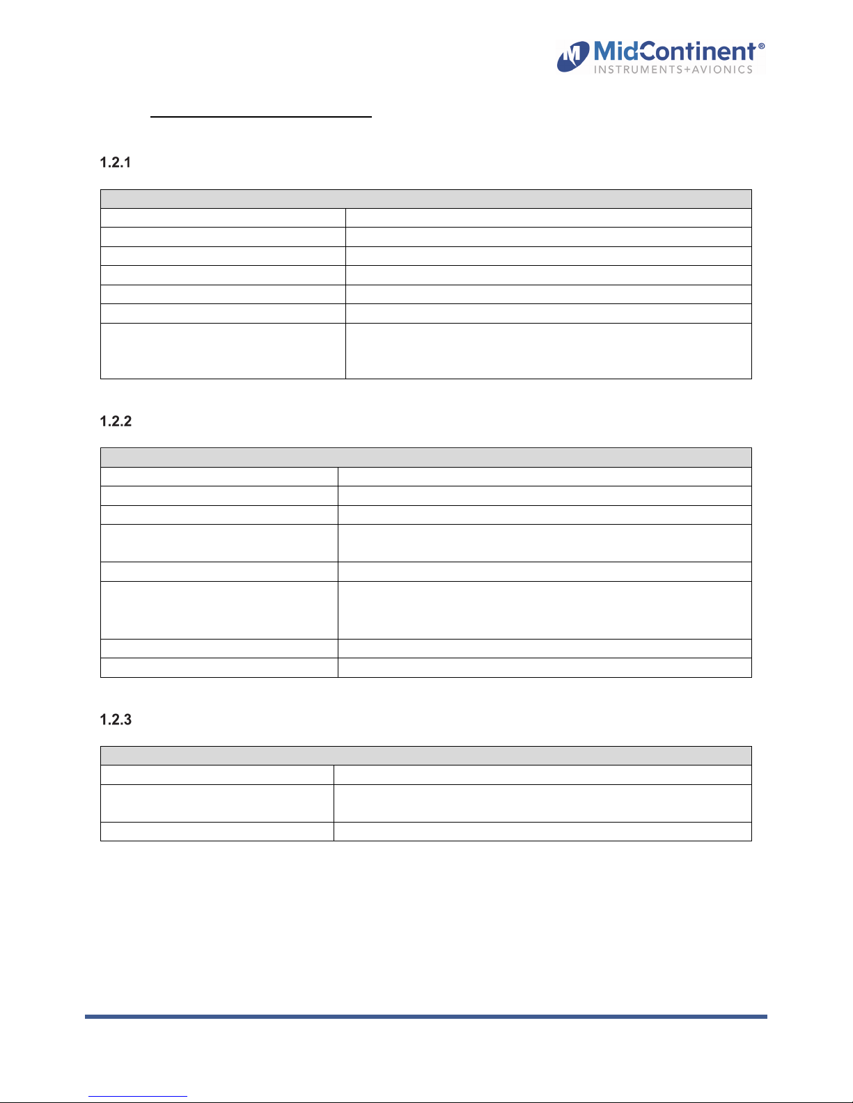
Electrical Attributes
Characteristics:
Input Voltage: 10-32 VDC
Input Power: (nominal) 3 watts (0.11A @ 28VDC)
(maximum) 9 watts max (when charging)
Battery Capacity (if installed): 3.3 watt-hours
Lighting Input: 5, 14, or 28VDC or automatic photocell control
Input Data: ARINC 429 (see Section 1.2.4)
Output Data: ARINC 429 (see Section 1.2.4);
Gillham encoded data (see Section 1.2.5)
Valid discrete signal to ground; invalid signal is open (pin 2)
Physical Attributes
Characteristics:
Range (altitude): -1,500 feet to 55,000 feet (-450 to 16,900 meters)
Range (baro): 28.00 to 31.00 IN HG (948 to 1050 MBAR)
Weight: 2.0 pounds (0.91 kg)
Dimensions:
(without connectors, mates & knob)
Cover Glass: HEA (anti-reflective) coated per MIL-C-14806
Mating Connectors:
Mounting: Front or rear mount, see panel cutout; Figure 3.1 and Figure 3.2
Lighting: Internally lit with white LEDs
Bezel: 2.27” x 2.27” x 0.23” (HxWxD)
Chassis: 2.18” x 2.18” x 4.63” (HxWxD)
9/16-18 UNJF-3B per MS33649-06 pneumatic fitting (MCI P/N
NY-400-1-6ST)
26-pin D-Sub, MCIA p/n 9018118 (Installation Kit)
Qualifications
Specifications:
Qualification: FAA TSO-C10b, C88b, C106, C179a
Environmental Qualification: RTCA DO-160G
Complex Hardware Qualification: RTCA DO-254, Design Assurance Level A
Manual Number 9018501
(details listed in Section 5.2)
7 Revision C, October 11, 2017
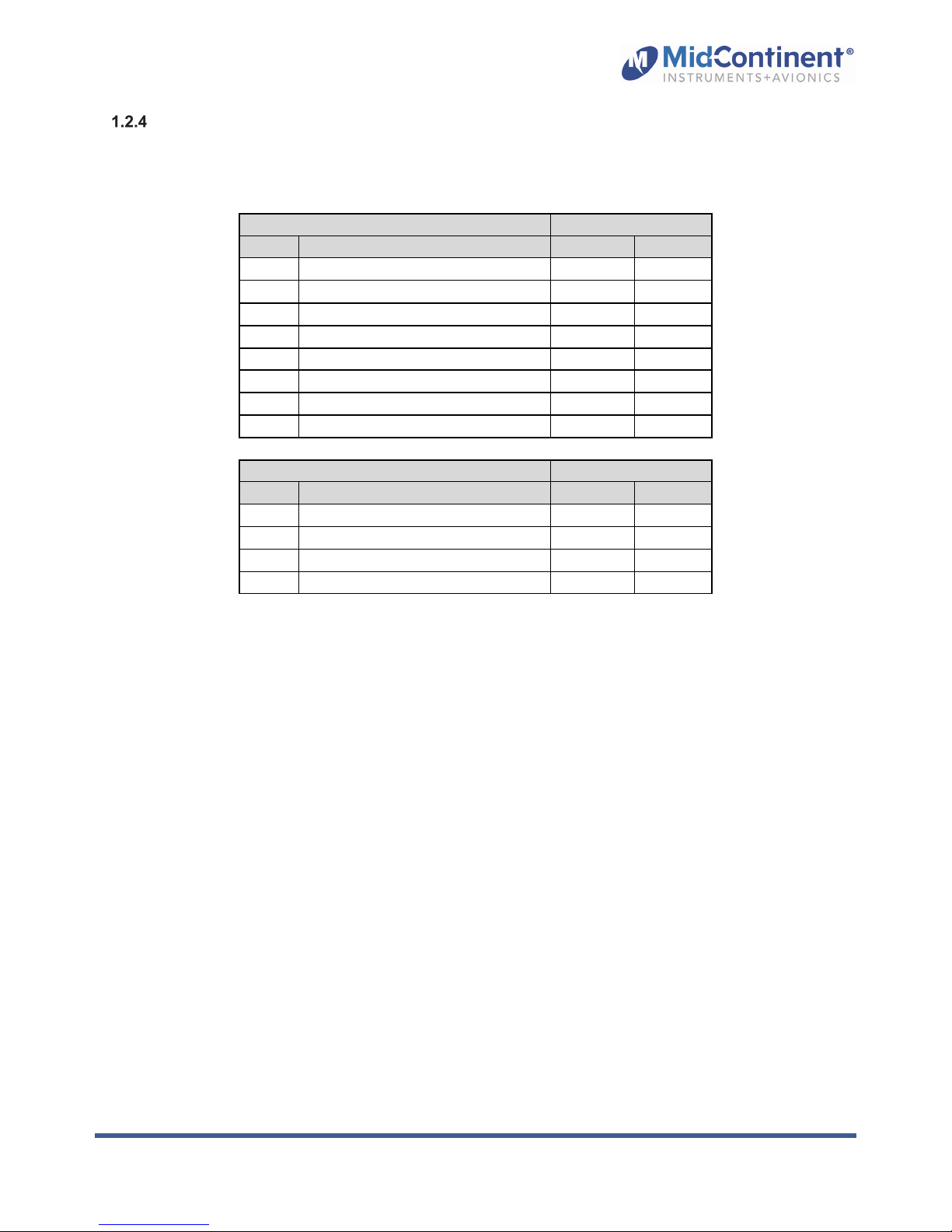
ARINC data labels
All labels are defined as Equipment ID 006 in BNR format.
ARINC 429 Output (Transmit) Speed
Label Description
203
Pressure Altitude
204
Baro Corrected Altitude
212 Altitude Rate X
217 Static Pressure, Corrected X
234 Baro Correction (mbar) X
235 Baro Correction (in Hg) X
350 Hardware Version (custom) X
377 Equipment ID (006) X
ARINC 429 Input (Receive) Speed
Label Description
203
Pressure Altitude
204
Baro Corrected Altitude
234 Baro Correction (mbar) X X
235 Baro correction (in Hg) X X
Table 1.1
ARINC Data Labels
High
X
X
High
X
X
Low
Low
X
X
Manual Number 9018501
8 Revision C, October 11, 2017
 Loading...