

Page 1
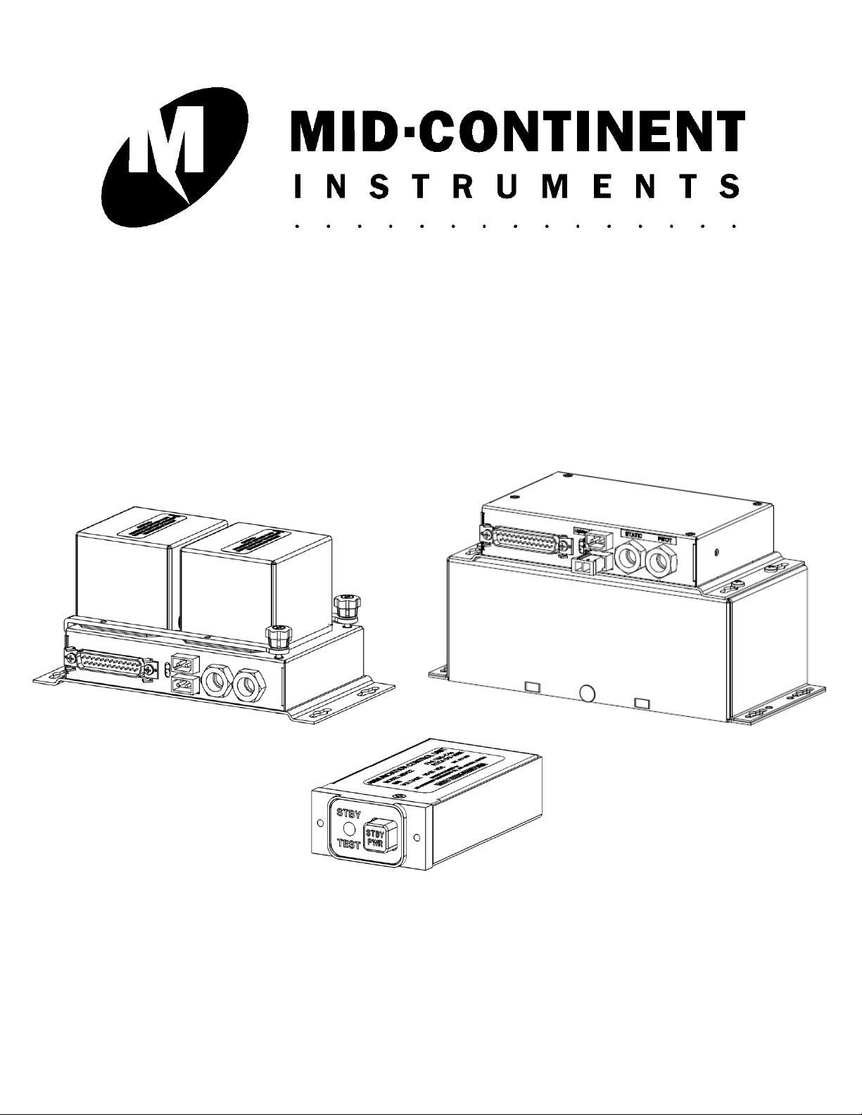
MD421
MD421-1
MD422
INSTALLATION MANUAL AND
OPERATING INSTRUCTIONS
MD420 and MD420-1
Emergency Power Systems
REV. J March 9, 2010 MANUAL NUMBER 9016391
Page 2

Mid-Continent Instruments, Wichita, KS
Copyright 2010
Mid-Continent Instrument Co., Inc.
Rev J, March 9, 2010 Manual Number 9016391 Page 2 of 19
Page 3

Mid-Continent Instruments, Wichita, KS
Table of Contents
Page
Section 1 General Description 5
1.1 Purpose of Equipment 5
1.2 Physical Description 5
1.3 Functional Description 5
1.4 Specifications 6
Section 2 Installation 7
2.1 General 7
2.2 Pre-Installation Inspection 7
2.3 Parts 7
2.3.1 Included Parts 7
2.3.2 Installer Supplied Parts 7
2.3.3 Additional Optional Parts 7
2.4 Equipment Location 8
2.5 Installation 8
2.5.1 Mounting the MD422 Annunciation Control Unit 8
2.5.2 Mounting the MD421/MD421-1 Battery Module 8
2.5.3 Installation Completion 9
2.5.4 Settings and Verification 9
2.6 Continued Airworthiness 10
2.6.1 Battery 10
Section 3 Operation 16
3.1 Standby Battery Operations 16
3.2 Equipment Limitations 19
Figure No. List of Illustrations
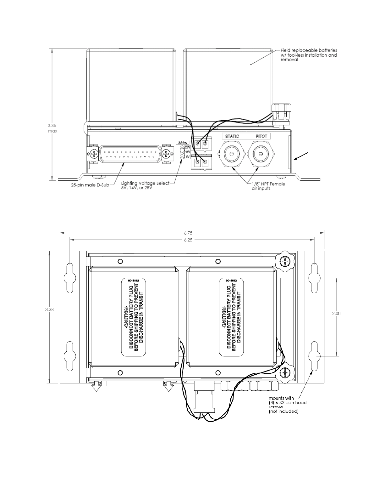
2.1 MD421 Battery Module Mounting Dimensions 12
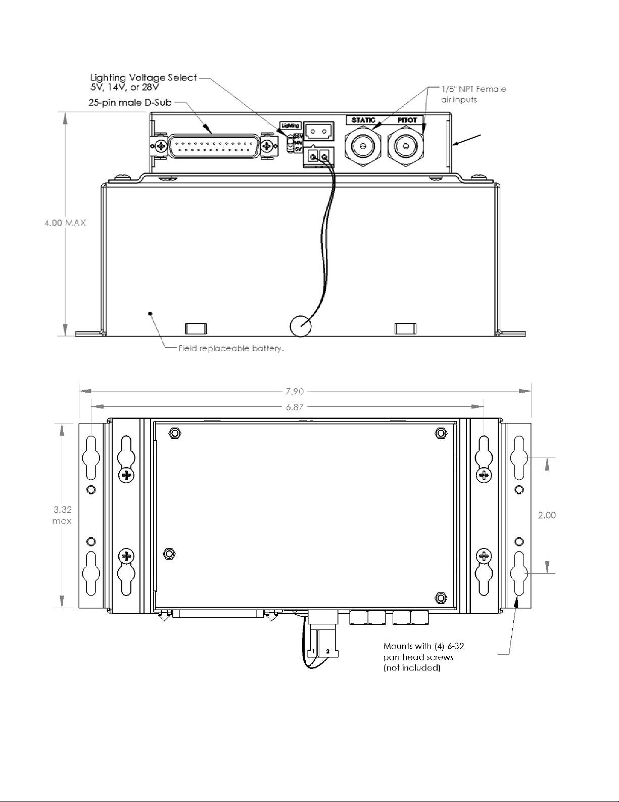
2.2 MD421-1 Battery Module Mounting Dimensions 13
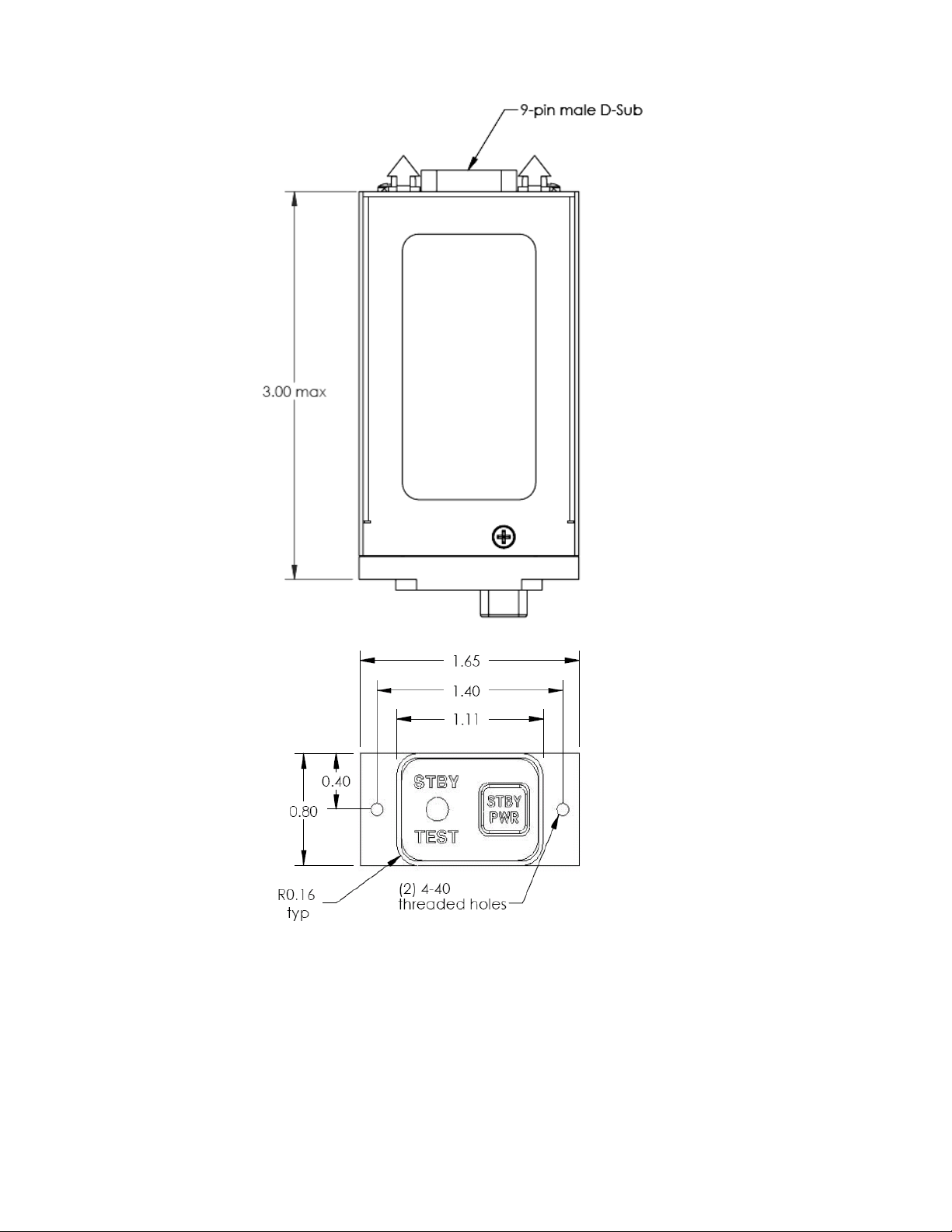
2.3 MD422 ACU Panel Cutout Dimensions 14
2.4 Installation Wiring 15
3.1 Nominal Battery Discharge Rate at 20°C 18
3.2 Battery Discharge Rate at 20°C for the MD420 18
3.3 Battery Discharge Rate at 25°C for the MD420-1 18
3.4 Effect of Low Temperature on Battery Capacity 19
3.5 Life Characteristics in Standby Use 19
Table No. List of Tables
1.1 MD421 Battery Module Physical Characteristics 6
1.2 MD421-1 Battery Module Physical Characteristic 6
1.3 MD422 ACU Physical Characteristics 6
1.4 MD420 EPS System Performance 6
1.5 MD420-1 EPS System Performance 6
Rev J, March 9, 2010 Manual Number 9016391 Page 3 of 19
Page 4

Mid-Continent Instruments, Wichita, KS
ECO
Rev.
Date
Detail
1 09/07/06
Preliminary release.
A 12/11/06
Production release.
4768
B
12/20/06
Revise 2.4C. Add 14V option to Figure 2.3.
4814
C
04/02/07
Remove “pending” status of TSO and DO-160 in Tables 1.1 and 1.2.
4933
D
11/02/07
Add further detail to automatic operation description in Section 1.3. Add
replacement battery p/n to 2.3.3. Add second paragraph to 3.1A.
4956
E
12/13/07
Update DO-160 qualification in section 1.4 from …[WW] to …[WF]… and
from …[A3C3]… to [A3H33].
4982
F
02/21/08
Update paragraph 1.3 and 2.5.2
5015
G
04/18/08
Update Table 1.3, Paragraph 2.5.2 and fig. 2.3
5123
H
12/02/08
Add note & warning in Paragraph 2.5.2
5345
J
03/09/10
Updated document to include MD421-1 information. Reduced information
in Section 1.3 in lieu of equivalent info in Section 3. Added Power Loss
Warning Disable feature in Section 3.1B, 2.5.2, and Figure 2.4.
Revision Detail
Rev J, March 9, 2010 Manual Number 9016391 Page 4 of 19
Page 5

Mid-Continent Instruments, Wichita, KS
Section 1: General Description
1.1 Purpose of Equipment
The MD420/MD420-1 Emergency Power Supply (EPS) System is designed to supply emergency power to
the Mid-Continent Instrument 4200 or 4300 series attitude indicator, or other applicable equipment, when
the aircraft main power buss has been de-energized. Additionally, the MD420/MD420-1 EPS System will
supply emergency lighting power to two additional instruments such as an airspeed and altimeter. During
normal aircraft operation, the MD420/MD420-1 EPS System will utilize the aircraft main power buss to
recharge or maintain existing charge on the System.
1.2 Physical Description
The MD420 EPS system consists of two components, the remote mounted MD421 Battery Module and the
MD422 panel mounted Annunciation Control Unit (ACU).
The MD420-1 EPS system consists of two components, the remote mounted MD421-1 Battery Module
and the MD422 panel mounted Annunciation Control Unit (ACU).
1.3 Functional Description
The MD421/MD421-1 Battery Module requires 10 to 32 VDC input voltage for in-flight charging and
operation in normal mode. The Battery Module routes aircraft main power to the associated equipment
(possibly an attitude gyro or other associated load) in normal power conditions. Upon loss of power, the
primary output will supply 15-18 volts of power to the load. Additional outputs are provided to power two
incandescent (2 bulbs each) or LED light trays in addition to the lighting for the primary load. Lighting
voltage is selectable for 5, 14 or 28 volts on the front of the MD421/MD421-1 Battery Module. Output
voltage is intended to power a Mid-Continent Instruments model 4200 or 4300 attitude indicator for one
(1) hour under typical conditions. Run time for alternate equipment will vary based on power
requirements.
The MD422 ACU controls the standby battery functions and provides annunciation of the current
operating mode. The ACU can annunciate a Power Loss Warning (flashing amber “STBY” light), can
annunciate when the battery is providing power (dim amber “STBY” light), and can test status when
activated (red or green “TEST” light). The white backlit “STBY PWR” button has multiple functions and
can be used to turn the battery on, turn the battery off, or initiate the self-test function.
The MD421/MD421-1 Battery Module contains pitot and static ports that, when connected, will
automatically switch on emergency power when power is lost and in-flight conditions are detected without the need to press the STBY PWR button on the MD422 ACU. This automatic function utilizes
airspeed of approximately 60 knots to determine validity of flight. An electrical signal from an external
sensor (such as a squat switch) can also be supplied to the unit as an alternative method to verify flight.
Neither of these automatic methods is required to be employed. Manual operation can still be used as
described previously.
Refer to an FAA authorized maintenance facility for testing and maintenance of this system.
Rev J, March 9, 2010 Manual Number 9016391 Page 5 of 19
Page 6

1.4 Specifications
MD421 Battery Module Physical Characteristics:
Qualification:
FAA-TSO-C4c
Environmental Qualification:
RTCA DO-160E
D1S2AER(B1G)XXXXXXZZAZ[ZC][WF]M[A3H33]XXAX
Weight:
3.1 pounds
Dimensions:
6.75 inches long by 3.35 inches high by 3.38 inches wide
Mating Connector:
MD25F20JVL0 25 pin D-Sub or equivalent (MCI P/N 7014517)
Mounting:
Must be mounted inside the cabin/bulkhead
MD421-1 Battery Module Physical Characteristics:
Qualification:
FAA-TSO-C4c
Environmental Qualification:
RTCA DO-160E
D1S2AER(B1G)XXXXXXZZAZ[ZC][WF]M[A3H33]XXAX
Weight:
4.9 pounds
Dimensions:
7.90 inches long by 4.00 inches high by 3.38 inches wide
Mating Connector:
MD25F20JVL0 25 pin D-Sub or equivalent (MCI P/N 7014517)
Mounting:
Must be mounted inside the cabin/bulkhead
MD422 Annunciation Physical Characteristics:
Qualification:
FAA-TSO-C4c
Environmental Qualification:
RTCA DO-160E
D1S2AER(B1G)XXXXXXZZAZ[ZC][WF]M[A3H33]XXAX
Weight:
0.2 pounds
Dimensions:
Length behind panel (not including mating connector)
3.0 inches long by 0.8 inches high by 1.65 inches wide
Mating Connector:
MD9F20JVL0 9 pin D-Sub or equivalent (MCI P/N 8017287)
Instrument Panel Mounting:
Rear mount only. (template is MCI P/N 90176344)
Performance: MD421
Battery Capacity
1.0 amp-hour @ 0.05C rate (approx 60 minutes @ 0.5A)
Current Rating
0.25 A nominal input
1.0A maximum output
1.0A maximum output on lighting bus
Maintenance
Batteries should be replaced every three years.
Performance: MD421-1
Battery Capacity
2.5 amp-hours @ 0.1C rate (approx 60 minutes @ 1.8A)
Current Rating
0.25 A nominal input
1.8A maximum output
1.0A maximum output on lighting bus
Maintenance
Batteries should be replaced every three years.
Table 1.1
Table 1.2
Mid-Continent Instruments, Wichita, KS
Table 1.3
Table 1.4
Table 1.5
Rev J, March 9, 2010 Manual Number 9016391 Page 6 of 19
Page 7

Mid-Continent Instruments, Wichita, KS
Section 2: Installation
2.1 General
This section contains mounting, electrical connections, and other information required for installation.
After installation of cabling and before installation of the equipment, ensure that power is applied only to
the pins specified in the interconnection diagram.
2.2 Pre-installation Inspection
A. Unpacking: Carefully remove the MD421/MD421-1 Battery Module and MD422 Annunciation
Control Unit from the shipping container. The shipping container and packing materials
should be retained for use should these units require future shipment.
B. Inspect for Damage: Inspect the shipping container and units for any signs of damage
sustained in transit. If necessary, return the units to the factory using the original shipping
container and packing materials. File any claim for damages with the carrier.
C. CAUTION: The MD421/MD421-1 Battery Module is shipped with the battery
cables disconnected to prevent inadvertent operation of the unit during shipping.
If the cable was found connected when received, check the battery condition per section 3
and then reconnect the battery during installation if it checks out ok. The battery packs may
be permanently damaged by remaining discharged for extended periods.
2.3 Parts
2.3.1 INCLUDED PARTS
A. MD421/MD421-1 Battery Module
B. MD422 Annunciation Control Unit
C. D-Sub 25 Pin Mating Connector, MD25F20JVL0 or equivalent (MCI P/N 7014517).
D. D-Sub 9 Pin Mating Connector, MD9F20JVL0 or equivalent (MCI P/N 8017287).
E. Installation Manual (P/N 9016391)
2.3.2 INSTALLER SUPPLIED PARTS
A. MD421/MD421-1 Mounting Screws, 6-32 Pan head. Four (4) required.
B. MD422 Mounting Screws, 4-40 X 3/8” Flat or Pan Head Phillips screw.
Two (2) Required
2.3.3 ADDITIONAL PARTS THAT MAY BE REQUIRED
A. Materials to complete static and pitot installation (if used).
B. File Template (MCI P/N 9016344) to assist in MD422 ACU hole cutout.
C. Replacement battery for the MD421 (P/N 9015607).
D. Replacement battery for the MD421-1 (P/N 9016925).
Rev J, March 9, 2010 Manual Number 9016391 Page 7 of 19
Page 8

Mid-Continent Instruments, Wichita, KS
2.4 Equipment Location
The MD420/MD420-1 system should be located within the aircraft in accordance with the
following considerations:
A. The MD422 ACU indicator is ideally located in the instrument panel directly within the pilot's
normal line of sight. Installations that result in viewing angles in excess of 30 degrees may
reduce readability.
B. The power cable should not run adjacent to heaters, engine exhausts, or other heat sources.
Also, take care to route and tie the cable away from aircraft controls and cables.
C. For optimum battery performance it is recommended to mount the battery in a temperature
controlled section of the aircraft.
2.5 Installation
2.5.1 MOUNTING THE MD422 ANNUNCIATION CONTROL UNIT
Plan a location in the aircraft for the MD422 ACU to be mounted as close to the pilot’s field of view
as possible. Avoid mounting close to heater vents or other high heat sources. Allow a clearance of
at least 3 inches from back of unit for plug removal.
The indicator is secured in place behind the panel since it is designed for rear mount only. Make a
panel cutout as shown in Figure 2.2. Secure the indicator in place with two 4-40 x 3/8 flat or pan
head Philips screws.
2.5.2 MOUNTING THE MD421/MD421-1 BATTERY MODULE
The MD421/MD421-1 Battery Module may be mounted at various angles, see Figure 2.1. Locate
an area large enough to facilitate mounting of unit with connector, back shell, and air fittings (if
used) in place. Ensure area is clear of mechanical obstructions and is not impeding movement of
any other aircraft systems. Avoid mounting close to heater vents or other high heat sources. Allow
a clearance of at least 3 inches from front of unit for plug removal. The unit must be installed
inside the aircraft cabin.
The STBY indicator may light when the battery is first connected to the system. Momentarily push
the STBY PWR button on the MD422 ACU, twice if necessary, until the STBY light is off.
Manual Installation: In an in-flight emergency, with complete loss of aircraft power, the pilot
must press the STBY button for continued emergency battery operation. NOTE:
To avoid unexpected system operations when the pitot and static lines are not
connected, use only supplied fitting plugs or other non-sealing plugs.
Automatic Installation: If automatic operation is desired, the pitot and static lines may be
connected to the MD421/MD421-1 battery module. This will allow activation of the system during
power loss without pilot intervention.
****WARNING****
The recommended torque range for 1/8” NPT fittings is 45-65 in/lbs. Excessive
torque can damage the MD421/MD421-1 Battery Module. It is recommended to
use a thread sealant (i.e. Teflon tape) to prevent air leaks.
Rev J, March 9, 2010 Manual Number 9016391 Page 8 of 19
Page 9

Mid-Continent Instruments, Wichita, KS
An alternate method may also be used to signify validity of flight as an option to the pitot-static
connection. An external sensor that provides a ground signal to the unit may be used (such as
a squat switch, etc (not included)). If an external signal is used for automatic operation, verify
that the sensor can operate during main aircraft power loss. See Note 2 of Figure 2.4.
The Power Loss Warning Disable feature can be employed by wiring Pin 17 to ground. See Section
Section 3: Operation for a description of this feature and Figure 2.4 for the installation wiring
diagram.
2.5.3 INSTALLATION COMPLETION
After completing installation, plug the standby battery cables into the module. (Note: The MD4211 has a single cable and should be plugged into the lower receptacle.)
NOTE: The cable is disconnected for shipping to prevent accidental activation and
battery discharge in transit.
2.5.4 SETTINGS AND VERIFICATION
Set the desired instrument lighting voltage on the front of the MD421/MD421-1. The unit is
capable of supplying 5, 14, or 28VDC lighting capable voltages to support the lighting of the
attitude indicator and two other instruments. When in standby mode, the aircraft dimming
control on the lighting buss is not used. Lighting is supplied at approximately half of full
brightness.
The STBY PWR button on the MD422 ACU is backlit. Set the brightness of the button lighting
by adjusting the dimming potentiometer on the side of the MD421/MD421-1 battery module. It
is recommended to set the brightness for nighttime operation and to balance it with other light
sources on the instrument panel.
After aircraft power has been turned on, press and hold the STBY PWR button for
approximately three seconds. The “TEST” annunciator will illuminate green, indicating the
standby battery is functioning properly. If the “TEST” annunciation becomes red at any point
during the 1-minute test, the standby battery should be fully recharged. If the standby battery
fails to pass this short battery capacity test after 1 hour of charging, a full battery capacity test
and/or maintenance check should be performed. See Sect. 2.6.
Rev J, March 9, 2010 Manual Number 9016391 Page 9 of 19
Page 10

Mid-Continent Instruments, Wichita, KS
2.6 Continued Airworthiness
2.6.1 BATTERY
A. The battery mounted on the MD421/MD421-1 Battery Module is designed to be a user
replaceable item if desired. Recommended replacement interval for the standby battery is 3 years
due to diminished capacity. See section 2.3.3 for replacement battery part numbers.
NOTE: The standby battery contains lead. Do not dispose of in local land-fills or other
environmentally sensitive areas.
NOTE: Recycle the battery in accordance with state and local regulations. For recycle
locations visit www.rbrc.com or call 1-800-8-BATTERY (1-800-822-8837)
B. In normal use, the MD421/MD421-1 Battery Module supplies the proper float charge voltage to
maintain its battery at peak capacity; however, the battery will slowly self-discharge if left unused
for long periods (over 3 months). In addition, self-discharge rates are directly related to the
storage temperature. The higher the storage temperature the faster the self-discharge rate.
Therefore, the battery should be periodically charged or removed from the installation and
maintained on a charger.
C. If the MD421/MD421-1 Battery Module has not been operated for an extended period (more than
3 months), the standby batteries should be charged by one of the following methods:
1. MCI Battery Charger/Tester P/N 36029 may be used for the MD421 (not MD421-1). This
Battery Charger/Tester will fully recharge the battery and then automatically switch to
maintain a float charge indefinitely after initial charging is complete.
2. Power the MD421/MD421-1 Battery Module for approximately 15 hours at the rated input
voltage.
3. Float Charging: Disconnect the batteries from the MD421/MD421-1 base assembly. Connect
each battery to a voltage source (battery plug (pin 1) red wire = positive) of 20.4 to 20.6
VDC.
4. Routine Charging:
a. MD421; Disconnect the batteries from the unit. Connect each battery to a constant
voltage source (battery plug pin 1 red wire = positive) of 21.6 to 22.1 VDC with a current
limit of 0.1 amp maximum. When the charging current drops to approximately 5mA, or
remains unchanged for 30 minutes, the battery is fully charged and should be
disconnected. Leaving 21.6 to 22.1 VDC charge voltage on the battery for an extended
time will degrade its life. If continuous maintenance of the charge is desired, perform a
Float Charge as described above.
b. MD421-1; Disconnect the battery from the unit. Connect battery pack to a constant
voltage source (battery plug pin 1 red wire = positive) of 22 VDC with a current limit of
1.6 amp; after 8 hours the battery is fully charged. Leaving 22 VDC charge voltage on
the battery for an extended time will degrade its life. If continuous maintenance of the
charge is desired, perform a Float Charge as described above.
****WARNING****
Battery out gassing and a rotten egg odor may occur due to prolonged high
rate overcharging and may result in battery damage. MCI recommends that
the battery assembly be replaced if out gassing has occurred.
Rev J, March 9, 2010 Manual Number 9016391 Page 10 of 19
Page 11

Mid-Continent Instruments, Wichita, KS
D. On at least an annual basis, as well as any time there may be a question about battery
performance (life), a Full Capacity Test should be performed. To perform a Full Battery Capacity
Test use one of the following methods:
1. Automatic (MD421 only)
Use MCI Battery Charger/Tester P/N 36029 for MD421 only. When in the capacity test
mode, this Charger/Tester will fully charge the battery and measure the time required for
discharge (60 minutes minimum). The unit will then automatically switch to the
charge/float mode to maintain the standby battery at full charge.
2. Manual
a. Disconnect batteries from the MD421/MD421-1 base assembly.
b. Ensure each battery is completely charged and at or near normal room
temperatures (20-25°C). (Ref. Sect. 2.6.1C)
c. Connect battery to a load of 10 ohms (rated for > 40 watts) while monitoring the
battery voltage level. Note the time required for the battery voltage to drop below
15V with the load attached, immediately remove the load.
i. If the battery capacity test runs more than 58 minutes, the battery
should be capable of continued use after recharging is complete.
ii. If the battery voltage drops below 15.0 volts before 58 minutes, the battery
pack is nearing the end of its service life and should be replaced.
d. Recharge each battery immediately.
****WARNING****
The battery may be permanently damaged if it is left in a discharged
state. Recharge a discharged battery as soon as possible and maintain
with a float charge for maximum battery life.
Rev J, March 9, 2010 Manual Number 9016391 Page 11 of 19
Page 12
Mid-Continent Instruments, Wichita, KS
Adjustment for
button lighting
Figure 2.1 MD421 Battery Module Mounting Dimensions
Rev J, March 9, 2010 Manual Number 9016391 Page 12 of 19
Page 13
Mid-Continent Instruments, Wichita, KS
Adjustment for
button lighting
Figure 2.2 MD421-1 Battery Module Mounting Dimensions
Rev J, March 9, 2010 Manual Number 9016391 Page 13 of 19
Page 14
Mid-Continent Instruments, Wichita, KS
File Template (MCI P/N 9016344) may be purchased from Mid-Continent to assist in hole
cutout
Figure 2.3 MD422 Annunciation Control Unit Panel Cutout Dimensions
Rev J, March 9, 2010 Manual Number 9016391 Page 14 of 19
Page 15

Mid-Continent Instruments, Wichita, KS
10-32VDC AIRCRAFT POWER INPUT
PRIMARY INSTRUMENT LIGHTING GROUND
PRIMARY INSTRUMENT POWER
12
13
reserved
6
7
4
1
5
3
8
11
9
10
2
PRIMARY INSTRUMENT POWER GROUND
AIRCRAFT LIGHTING BUS GROUND
PRIMARY INSTRUMENT LIGHTING POWER
5V, 14V, OR 28V AIRCRAFT LIGHTING BUS INPUT (NOTE 1)
AIRCRAFT POWER GROUND
21
16
15
18
19
20
17
14
23
22
24
25
reserved
reserved
POWER LOSS WARNING DISABLE
AIR SWITCH
reserved
ANNUNC SENSOR
STDBY PWR SWITCH
ANNUNC RED
ANNUNC GROUND
ANNUNC GREEN
ANNUNC WHITE
ANNUNC AMBER
THIRD INSTRUMENT LIGHTING GROUND
SECOND INSTRUMENT LIGHTING GROUND
SECOND INSTRUMENT LIGHTING POWER
THIRD INSTRUMENT LIGHTING POWER
MD422 ANNUNCIATOR
3
ANNUNC GROUND
ANNUNC SENSOR
2
6
STDBY PWR SWITCH
8
ANNUNC WHITE
5
ANNUNC YEL
4
ANNUNC RED
ANNUNC GREEN
1
7
reserved
9
reserved
NOTE:
1) INSTALLER MUST SELECT 5V, 14V, OR 28V LIGHTING
ON THE MD421/MD421-1 BATTERY MODULE.
2) PIN 18 MAY BE USED INSTEAD OF
CONNECTING THE PITOT AND STATIC PORTS. A
GROUND ON PIN 18 WHEN THE AIRCRAFT IS IN
FLIGHT WILL ALLOW FOR FULL AUTOMATIC BACKUP
POWER WHEN AIRCRAFT POWER IS LOST. SEE
SECTION 2.5.2.
3) USE 22 GAUGE (OR HEAVIER) WIRE FOR THE
MD421/MD421-1 POWER AND GROUND. ALSO USE 22
GAUGE (OR HEAVIER) WIRE FOR PRIMARY POWER
AND GROUND. ALL OTHER CONNECTIONS MAY BE
24 GAUGE.
MD421/MD421-1 BATTERY MODULE
Rear view of MD422 ACU Mating Connector
Rear view of MD421/MD421-1 Battery Module Mating Connector
Rev J, March 9, 2010 Manual Number 9016391 Page 15 of 19
Figure 2.4 Installation Wiring
Page 16

Mid-Continent Instruments, Wichita, KS
Section 3: Operation
3.1 Standby Battery Operation
When aircraft power is supplied to the MD420/MD420-1 Emergency Power Supply system, the internal
standby battery will automatically maintain a full charge.
During loss of aircraft power, the MD420/MD420-1 EPS system provides emergency lighting power to the
primary load and two additional instruments. The brightness for the instrument lighting during power loss
is preset to approximately half of full brightness. The installer may wish to adjust the lighting level of the
STBY PWR button on the MD422 ACU to an optimal level under low light conditions. This adjustment is
located on the right side of the MD421/MD421-1 Battery Module. See Figure 2.1.
A. After turning off main power:
When the MD420/MD420-1 EPS senses power loss, the unit will indicate a Power Loss
Warning. The Power Loss Warning consists of the amber STBY annunciation on the MD422
ACU flashing brightly for approximately one minute. With no further action from the pilot, the
unit will turn off automatically after approximately one minute, and the STBY annunciation
will turn off. This is to prevent inadvertent battery discharge when the master power switch
is turned off and the aircraft is on the ground. See Power Loss Warning Disable below for
alternate installation options.
B. Loss of Aircraft Power in flight:
Manual Installation: When the MD420/MD420-1 EPS system senses power loss, the standby
system immediately provides power to the primary load and signals a Power Loss Warning.
The STBY indication will flash, and standby power will be supplied to attached equipment for
one minute. This is intended to attract the pilot’s attention and indicate that there has been
a loss of primary power. Pushing the STBY PWR button will allow the equipment to continue
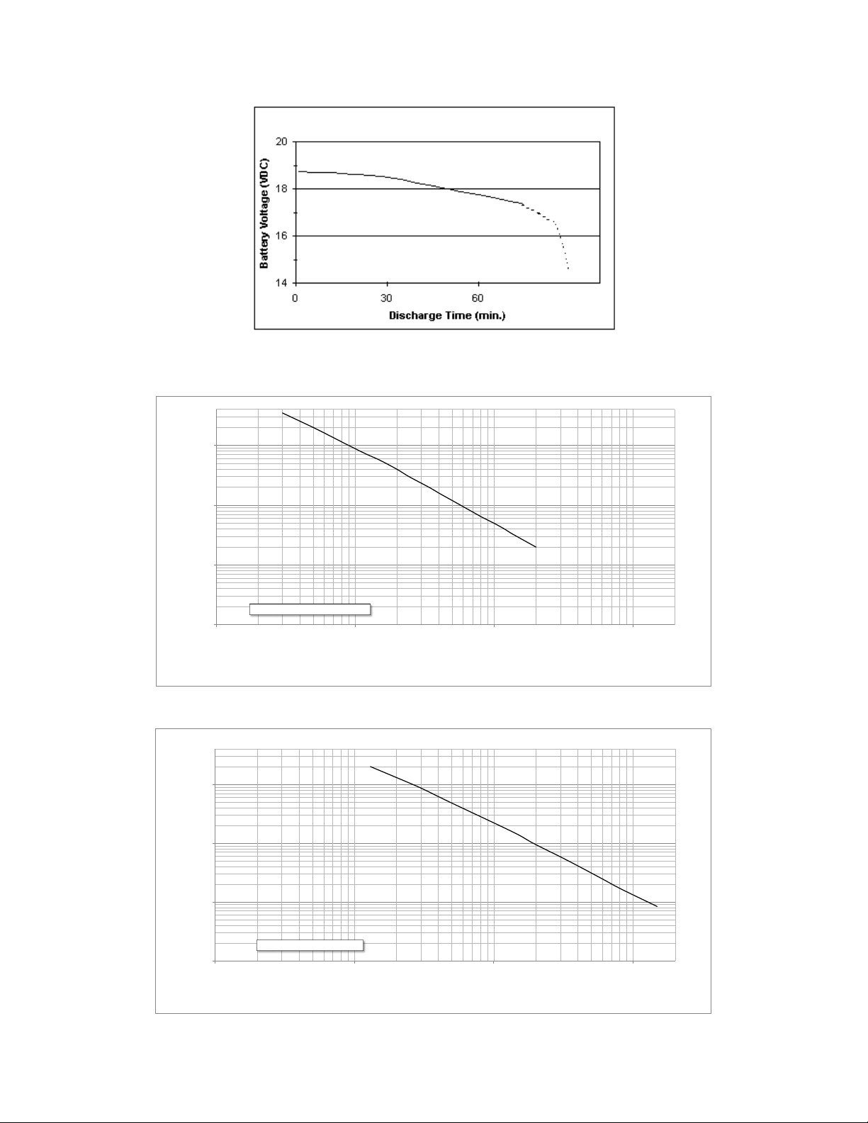
operating on the standby battery until the battery is exhausted. (See Fig 3.1, 3.2, and 3.3 for
more information on battery discharge rate.) The STBY annunciation will remain dimly lit,
indicating that the equipment is running on standby battery power. If the STBY PWR button
is not activated within one minute, the MD420/MD420-1 system and attached equipment will
shut down.
Automatic Installation: If the pitot-static system is connected to the MD421/MD421-1 battery
module or an external sensor signal is supplied to the unit, no action is required by the pilot
when the MD420/MD420-1 EPS senses power loss during flight. During power loss, the
standby battery immediately provides power to the attitude indicator and the amber STBY
annunciation on the MD422 ACU will be dimly lit.
NOTE: For both Manual and Automatic Installations:
Any time aircraft power is absent; either during the Power Loss Warning or after shut off,
pushing the STBY PWR button will put the unit in the standby power mode. This applies
either during flight or on the ground. The instrument will run from standby power until the
standby battery is exhausted. To turn off the MD420/MD420-1 system during standby power
mode, push the STBY PWR button again. The amber STBY light will turn off and the attached
equipment will power off. Pushing the STBY button at any time when the unit is off will
restore standby power. Restoring aircraft power will clear any standby operation mode and
resume automatic battery charging.
Rev J, March 9, 2010 Manual Number 9016391 Page 16 of 19
Page 17

Mid-Continent Instruments, Wichita, KS
Power Loss Warning Disable: The Power Loss Warning is the flashing amber “STBY” light that
is activated when aircraft power is lost, either in flight or when turned off on the ground. This
feature can be disabled if desired, bypassing the 1-minute flashing time out. Thus, after
turning off main power on the ground, the unit will immediately turn off with no additional
indications. The unit will also turn off without indication (not supply standby power)
immediately in flight if power is lost and if not configured for automatic operation. NOTE:
This feature is not recommended for installation when the EPS is configured for manual
operation! If configured for automatic operation, the unit will function normally as described,
automatically entering standby power mode without the Power Loss Warning and without
pilot intervention. If the flight valid signal (pitot-static or electrical signal) were not available,
the unit would turn off with loss of input power. The EPS can always be activated at any time
by pressing the STBY PWR button.
C. Standby Battery Test:
The MD422 ACU incorporates a manual test feature. This test feature places the standby
battery system under a load for approximately one minute (the gyro is used as a load) while
displaying the “TEST” annunciation as either green (PASS) or red (FAIL).
To initiate this test:
1. Turn on the MD420/MD420-1 Emergency Power Supply system with aircraft power.
2. Press and hold the STBY PWR button on the MD422 ACU. After several seconds the
amber STBY will start flashing, indicating the unit has latched into Battery Test Mode.
The STBY PWR button can now be released. The test runs for approximately one
minute, during which time the amber STBY flashes continuously and either a red or
green light is displayed under the word TEST.
3. Visually monitor the test lights until the amber STBY stops flashing, signaling the end
of the test.
4. A green “TEST” light throughout the test indicates the MD421/MD421-1 Battery
Module is healthy and should function normally. A red light at any time during the
test means that the battery module is at least in need of charging, and possibly of
replacement.
Note:
A green light throughout this short test does not guarantee that a full hour of
operation time is available. Actual operation time may vary depending on
temperature, charge status, and battery condition. (See Sect. 2.6 for more details.)
Complete charging may be required to bring the battery module up to full charge if it has
been stored for more than four months or if it has been partially discharged. If a steady red
light is observed at any time during the test, charge the MD421/MD421-1 Battery Module
completely, using one of the methods described in section 2.6 and retest the system. If after
charging, the test still fails, service may be required.
The test function is only available when aircraft power is present.
Rev J, March 9, 2010 Manual Number 9016391 Page 17 of 19
Page 18
Mid-Continent Instruments, Wichita, KS
0.0
0.1
1.0
10.0
0.01 0.10 1.00 10.00
Discharge Capacity (Hours)
Discharge Load (Amps)
MD421 Load vs. Capacity
@ ambient temp of 20 °C
0.0
0.1
1.0
10.0
0.01 0.10 1.00 10.00
Discharge Load (Amps)
Discharge Capacity (Hours)
MD421-1 Load vs. Capacity
@ ambient temp of 25°C
Fig. 3.1 Nominal Battery Discharge Rate at 20°C for the MD420 used with
Mid Continent Instruments 4200/4300 Attitude Indicator
Rev J, March 9, 2010 Manual Number 9016391 Page 18 of 19
Fig. 3.2 Standard Battery Discharge Rate at 20°C for the MD420
Fig. 3.3 Standard Battery Discharge Rate at 25°C for the MD420-1
Page 19
Mid-Continent Instruments, Wichita, KS
0
20
40
60
80
100
-20 -10 0 10 20 30 40 50
Capacity (%)
Temperature (°C)
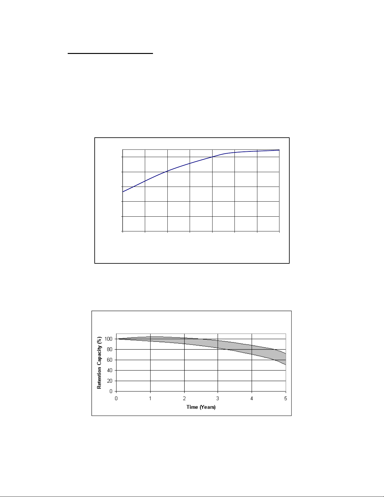
Fig. 3.4: Effect of Low Temperature
On Standby Battery Capacity
Fig. 3.5: Life Characteristics
In Standby Use
3.2 Equipment Limitations
Actual operation time on the MD420/MD420-1 Emergency Power Supply may vary considerably
depending on temperature, charge status, and battery condition. Low temperatures will temporarily
degrade battery capacity as shown in Fig. 3.4. Internal chemistry will slowly degrade battery capacity
over several years of operation as shown in Fig 3.5, even when correctly maintained. A poorly maintained
battery will suffer accelerated degradation in excess of the guidelines given in this document. Extended
storage in a discharged state or at high ambient temperatures, and over-charging will all permanently
damage a battery. Complete charging is required to bring the battery up to full capacity if it has been
stored for more than four months or if it has been partially discharged.
Rev J, March 9, 2010 Manual Number 9016391 Page 19 of 19
 Loading...