

Page 1
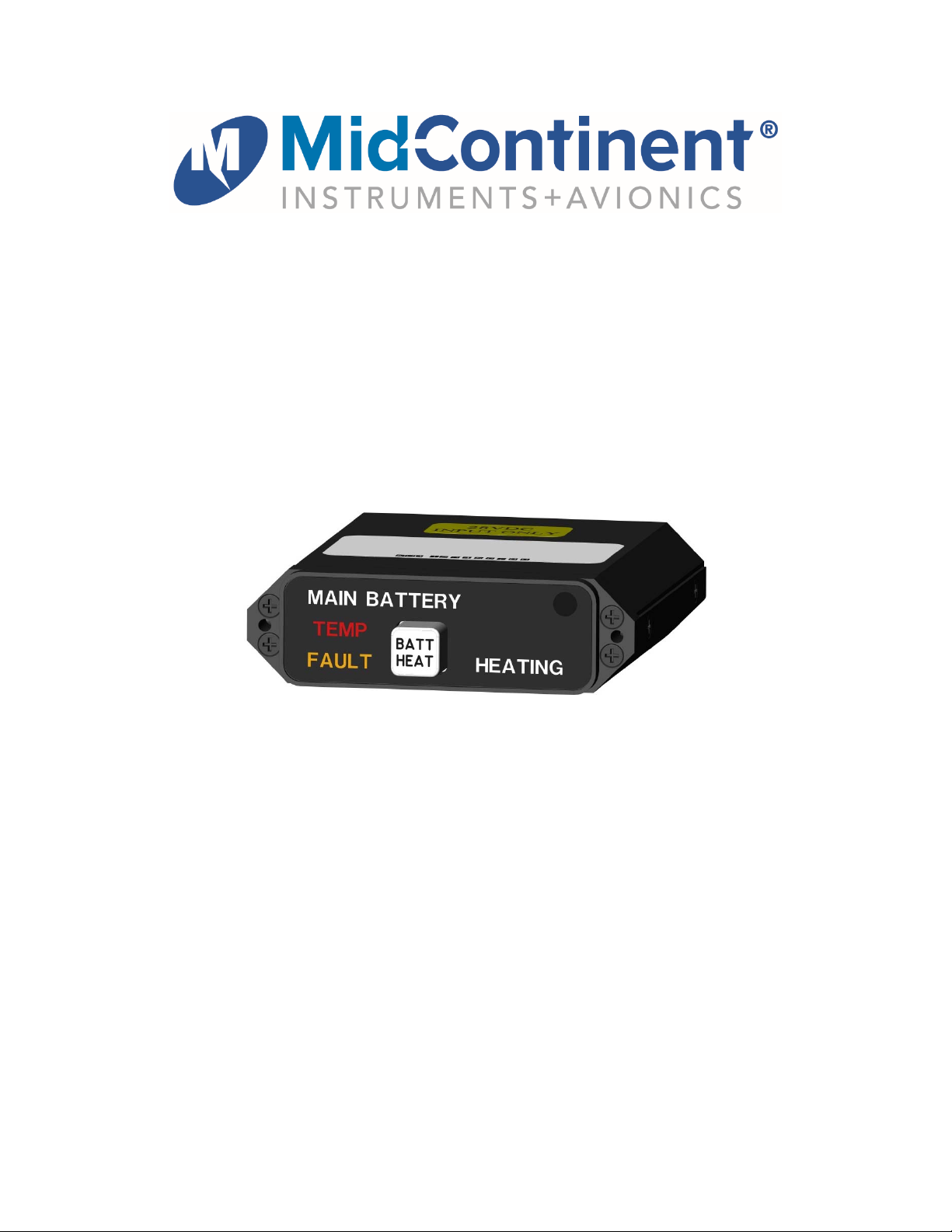
Installation Manual and Operating Instructions
MD41-1844
Annunciation Control Unit
for Lithium-ion Battery Systems
MD41-1844 28 VDC Horizontal Mount
Mid-Continent Instruments and Avionics
Mid-Continent Instrument Co., Inc.
dba Mid-Continent Instruments and Avionics
9400 E. 34th Street N.
Wichita, KS 67226 USA Manual Number 9018268
PH (800) 821-1212 FX (316) 630-0723 Revision A, May 18, 2015
®
Page 2

FOREWORD
This manual provides information intended for use by persons who, in accordance with current
regulatory requirements, are qualified to install this equipment. If further information is required,
please contact:
Mid-Continent Instruments and Avionics
Attn: Customer Service Dept.
9400 E. 34th Street N.
Wichita, KS 67226 USA
PH (316) 630-0101
FX (316) 630-0723
www.mcico.com
We welcome your comments concerning this manual. Although every effort has been made to
keep it free of errors, some may occur. When reporting a specific problem, please describe it
briefly and include the manual part number, the paragraph/figure/table reference and the page
number. Send your comments to:
Mid-Continent Instruments and Avionics
Attn: Technical Publications
9400 E. 34th Street N.
Wichita, KS 67226 USA
PH (316) 630-0101
FX (316) 630-0723
All products produced by Mid-Continent Instrument Co., Inc., including those identified as MidContinent Instruments and Avionics or True Blue Power
®
, are designed and manufactured in
Wichita, KS, USA.
Copyright 2015
Mid-Continent Instruments and Avionics
Manual Number 9018268 2 Rev. A May 18, 2015
Page 3

REVISION HISTORY
Rev. Date Detail
A 5/18/15 Production release.
Manual Number 9018268 3 Rev. A May 18, 2015
Page 4

TABLE OF CONTENTS
SECTION 1 GENERAL DESCRIPTION 5
1.1 INTRODUCTION 5
1.2 TECHNICAL SPECIFICATIONS 5
1.2.1 Model 5
1.2.2 Physical Attributes 5
1.2.3 Performance 5
SECTION 2 PRE-INSTALLATION CONSIDERATIONS 6
2.1 COOLING 6
2.2 EQUIPMENT LOCATION 6
2.3 ROUTING OF CABLES 6
2.4 LIMITATIONS 6
2.5 TECHNICAL SPECIFICATIONS 6
SECTION 3 INSTALLATION PROCEDURE 7
3.1 GENERAL INFORMATION 7
3.2 UNPACKING AND INSPECTING 7
3.2.1 Included Parts 7
3.2.2 Available Parts 7
3.3 CABLE HARNESS 7
3.3.1 Lighting Controls 8
3.3.2 Power And Signals 8
3.3.3 Harness Verification 8
3.4 MOUNTING 9
SECTION 4 OPERATION 10
4.1 FRONT PANEL CONTROLS AND ANNUNCIATIONS 10
4.1.1 Controls 10
4.1.2 Annunciations 10
4.1.3 Additional Information 11
SECTION 5 CONFORMANCE 11
5.1 CONTINUED AIRWORTHINESS STATEMENT 11
APPENDIX 1 12
NUMBER LIST OF TABLES AND FIGURES
Table 1 Model 5
Table 1 Physical Attributes 5
Table 3 Performance 5
Figure 1 25 Pin D-Sub Rear View Connector Pinout 7
Table 4 25 Pin D-Sub Connector Pinout 7
Figure 2 Wiring Diagram 8
Figure 3 Outline Drawing 9
Figure 4 Front Panel 10
Manual Number 9018268 4 Rev. A May 18, 2015
Page 5
SECTION 1 GENERAL DESCRIPTION
1.1 INTRODUCTION
The MD41-1844 product is compact, self-contained Annunciation and Control Unit (ACU). The fully
integrated control unit provides annunciation for Mid-Continent Instruments and Avionics TB44 battery
systems. It combines the necessary functions and annunciations required to interface with an approved
system.
Highlighted features include long-life LEDs used for all lighting, internally backlit selection switch, deadfront inactive annunciations, and automatic dimming. An external annunciation dimming adjustment is
provided for balancing low-level light conditions.
1.2 TECHNICAL SPECIFICATIONS
1.2.1 Model
MD41-1844
Orientation Horizontal
Power Input 28VDC
Lighting Input 28VDC
Table 1
Model
1.2.2 Physical Attributes
Characteristics:
Weight: 0.26 pounds
Dimensions:
(not including connector or mate)
Mating Connector: Positronic RD25S10JVL0 or equivalent (MCI P/N 7014517)
Instrument Panel Mounting: Rear mount
3.2 inches long
2.75 inches wide
0.8 inches high
Table 2
Physical Attributes
1.2.3 Performance
Specifications:
Power Requirement: 0.20 A max
Table 3
Performance
Manual Number 9018268 5 Rev. A May 18, 2015
Page 6

SECTION 2 PRE-INSTALLATION CONSIDERATIONS
2.1 COOLING
No direct cooling is required. As with any electronic equipment, overall reliability may be increased if the
unit is not located near a high heat source or crowded next to other equipment. Means of providing some
airflow is considered beneficial.
2.2 EQUIPMENT LOCATION
The MD41-1844 ACU must be mounted as close to the pilot’s field of view as possible. The unit depth,
with connector attached, must also be taken into consideration when selecting an appropriate location.
Allow at least 3 inches of space behind the unit for connector attachment and removal.
2.3 ROUTING OF CABLES
Care must be taken not to bundle the MD41-1844 ACU logic and low level signal lines with any high
energy sources. Examples of these sources include 400 HZ AC, Comm, DME, HF and transponder
transmitter coaxial cables. Always use shielded wire when shown on the installation print.
Avoid sharp bends in cabling and routing near aircraft control cables. Also avoid proximity and contact
with aircraft structures, avionics equipment, or other obstructions that could chafe wires during flight and
cause undesirable effects.
2.4 LIMITATIONS
Note that this product is part of an incomplete system. It is designed to be installed with other applicable
equipment to provide functionality for main battery systems.
2.5
TECHNICAL SPECIFICATIONS
The MD41-1844 ACU complies with the manufacturers’ specifications and has been verified and
approved for use with the following systems:
Mid-Continent Instruments and Avionics
Model Number(s):
Designed for use with
Battery System:
MD41-1844
Manual Number 9018268 6 Rev. A May 18, 2015
Manufacturer: True Blue Power
Model(s): TB44
Page 7
SECTION 3 INSTALLATION PROCEDURE
3.1 GENERAL INFORMATION
This section contains interconnect diagrams, mounting dimensions and other information pertai ning to the
installation of the MD41-1844 ACU. After installation of cabling and before installation of the equipment,
ensure that power is applied only to the pins specified in the interconnect diagram.
3.2 UNPACKING AND INSPECTING EQUIPMENT
When unpacking this equipment, make a visual inspection for evidence of any damage that may have
incurred during shipment.
3.2.1 Included Parts
A. Main Battery ACU MCI P/N MD41-1844-( )
B. Installation Manual MCI P/N 9018268
3.2.2 Available Parts
A. J1 Connector Kit (25 pin) MCI P/N 7014517
3.3 CABLE HARNESS
The MD41-1844 ACU cable harness should be made using 24 AWG wire or larger for all connections.
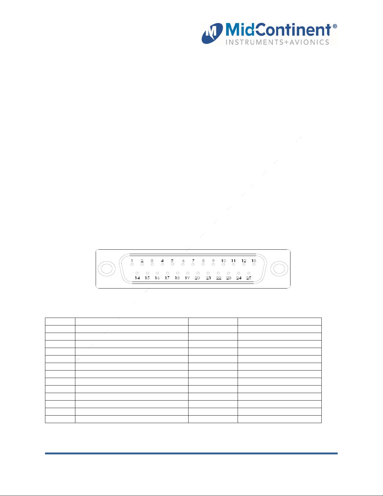
Construct the cable harness with regards to the instructions below and using the Connector Pinout of
Figure 1, Schematic Pinout of Table 4, and Wiring Diagram of Figure 2.
PIN#
1 Pin1 of RTD1 14 Pin2 of RTD1
2 Pin2 of RTD2 15 Battery Maint High
3 Input from Pin2 of RTD2 16 Battery OK High
4 Battery Fail High 17 Battery OK Low
5 Output to Pin1 of RTD1 18 Battery Fail Low
6 Isolated Ground 19 Battery Maint Low
7 Heater Enable 20 Battery Enable
8 Overheat Warning Low 21 Reserved
9 Overheat Warning High 22 Reserved
10 External Switch (Battery/Heater) 23 Reserved
11 Reserved 24 Ground
12 Battery 28 VDC 25 Ground
13 Avionics Bus 28 VDC
MAIN BATTERY
Rear View of 25 Pin D-Sub Connector (J1)
Figure 1
PIN#
Table 4
25 Pin D-Sub Connector Pinout
MAIN BATTERY
Manual Number 9018268 7 Rev. A May 18, 2015
Page 8
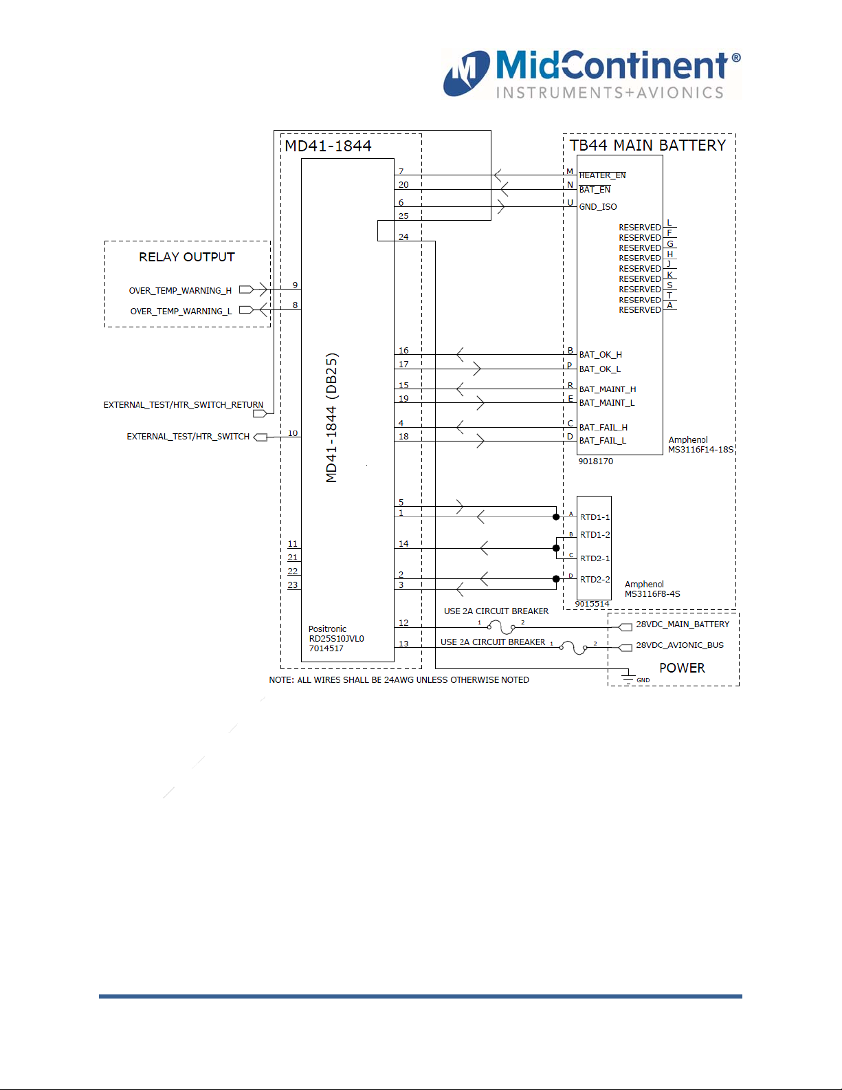
Figure 2
Wiring Diagram
Refer to Section 2: Pre-Installation Considerations in regards to routing precautions.
3.3.1 Lighting Control
Brightness will be automatically controlled by the internal photocell and the dimming circuit.
3.3.2 Power And Signals
Wire aircraft avionic bus power and aircraft ground according to the associated ACU pin s in
the Pinout Diagram. Annunciation signals should be wired from the appropriate system inputs
and outputs to the associated ACU pins in the Pinout Diagram.
3.3.3 Harness Verification
With the MD41-1844 ACU disconnected, turn on the avionics master switch and use an ohmmeter to verify that aircraft avionic bus power is on the appropriate pin(s) with appropriate
voltage. Also verify that aircraft ground is applied to the appropriate pins.
Manual Number 9018268 8 Rev. A May 18, 2015
Page 9
3.4 MOUNTING
Refer to Section 2: Pre-Installation Considerations in regards to equipment location.
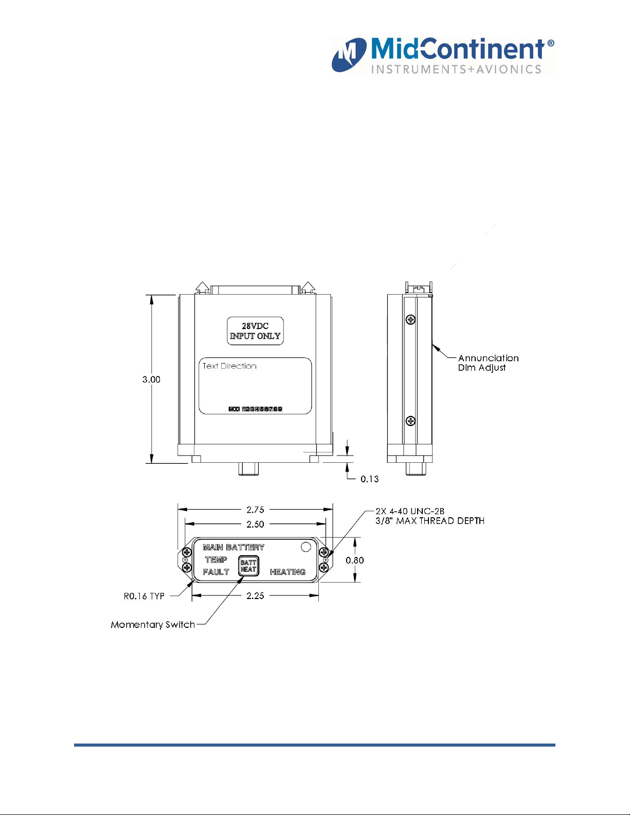
The MD41-1844 ACU is designed for rear panel mounting only. A cutout should be made in the panel in
accordance with Figure 3 for the unit bezel and two mounting holes. A cutout template is available from
Mid-Continent Instruments and Avionics (reference p/n 8014474) upon request.
Prior to completing the mounting of the unit in the aircraft, make sure to set the Annunciator Dim
Adjustment for the annunciations. Ideally this procedure is best performed in a dark cockpit to simulate
low-light/night time conditions. Connect the unit to the cable harness and turn on master power to the
instrument panel and lighting bus. Use a small flat-bladed screwdriver to access the adjustment screw
inside the hole on the bottom of the unit. Adjust the screw to increase or decrease the annunciator lighting
brightness to a level appropriate with the rest of the panel instrument lighting.
Secure the indicator to the panel with two #4-40 x 3/8 flat head Phillips screws.
Figure 3
Outline Drawing MD41-1844
Manual Number 9018268 9 Rev. A May 18, 2015
Page 10
SECTION 4 OPERATION
4.1 FRONT PANEL CONTROLS AND ANNUNCIATIONS
4.1.1 Controls
BATT/HEAT
4.1.2 Annunciations
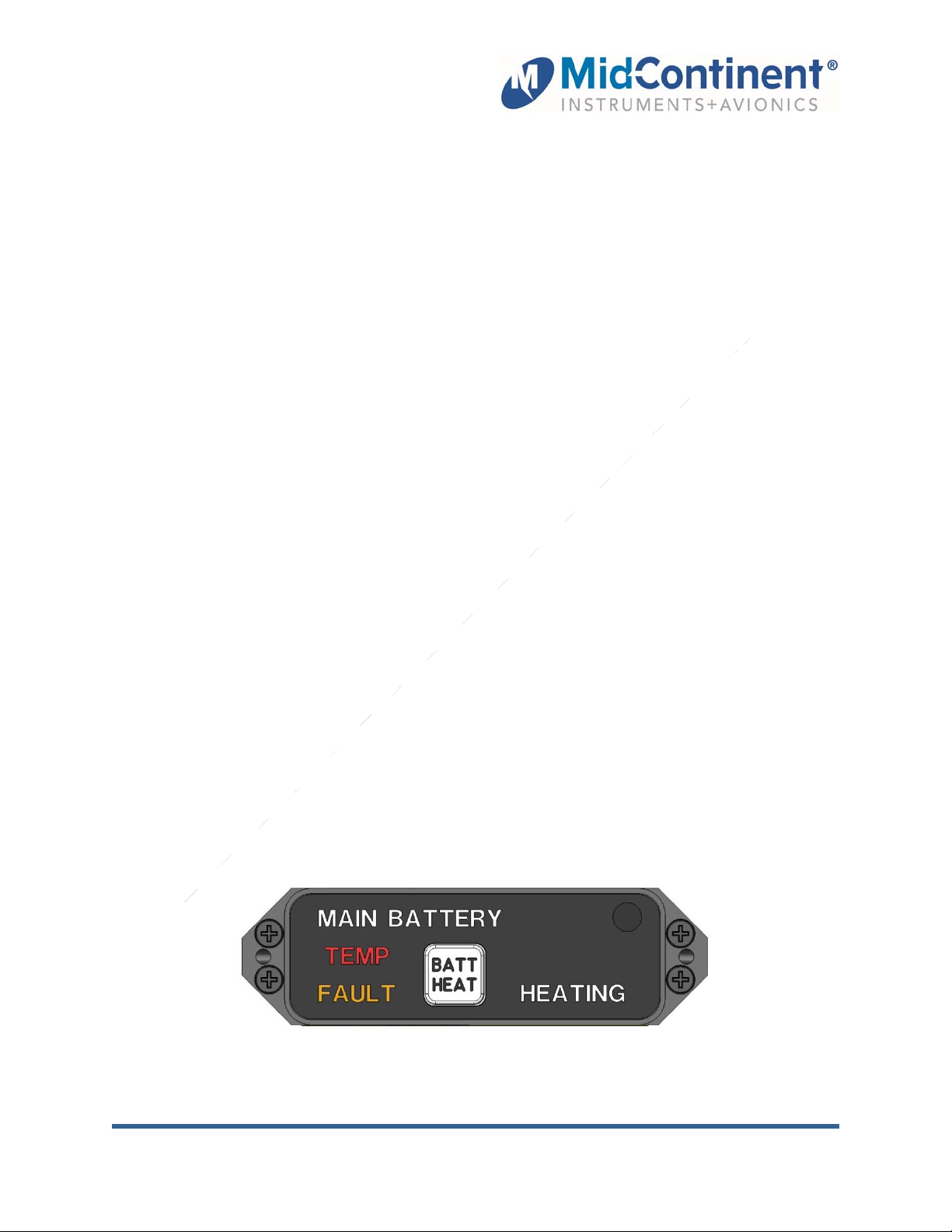
MAIN BATTERY (WHITE) Lit when any of the annunciations are ON.
Avionics bus (power to Annunciator) is OFF:
• Pressing the BATT/HEAT momentary switch for less than two seconds lights all
annunciations (as depicted in Figure 4) while the switch is activated.
• Pressing and holding the BATT/HEAT momentary switch for two seconds or more
enables the TB44 battery Central Monitoring System (CMS) and heater circuitry. It
may take up to 15 seconds after releasing the switch until valid annunciations are
displayed.
o While the switch is pressed all annunciations will be on.
o The CMS and heater circuitry will be active for two hours, enabling heaters
to operate if the temperature is less than -3 °C.
o During this two hour period, the BATT/HEAT light will be on.
o After two hours have elapsed, the CMS and heater circuitry will be inactive
and the BATT/HEAT light will turn off.
Avionics bus (power to Annunciator) is ON:
• The battery is enabled and the BATT/HEAT light will be on.
• Pressing the BATT/HEAT momentary switch for any length of time lights all
annunciations when switch is activated.
TEMP (RED) Over temperature sensed on battery. Land as soon as
practical and present the battery for maintenance
evaluation.
FAULT (AMBER) Present battery for maintenance upon landing.
BATT/HEAT (WHITE) Lit when battery is enabled.
HEATING (WHITE) Battery heater is activated due to unit temperature below
-3 °C and battery is in active state. It is recommended
that an engine start not occur until the HEATING
annunciation turns off.
Figure 4
Front Panel
Manual Number 9018268 10 Rev. A May 18, 2015
Page 11

4.1.3 ADDITIONAL INFORMATION
Refer to the installation manual and operating instructions of the TB44 for additional
operational and functional interface details.
SECTION 5 CONFORMANCE
5.1 CONTINUED AIRWORTHINESS STATEMENT
No periodic scheduled maintenance or calibration is necessary for continued airworthiness of the MD411844 ACU. If the unit fails to perform to specifications, the unit must be removed and serviced by MidContinent Instruments and Avionics or their authorized designee.
Manual Number 9018268 11 Rev. A May 18, 2015
Page 12

Appendix 1
DO-160 Environmental Qualification Form
MODEL NUMBER: MD41-() PART NUMBER: MD41-1844
NOMENCLATURE: MD41-() Battery Annunciation Control Unit
TSO APPROVALS: N/A
MANUFACTURER: Mid-Continent Instrument Co., Inc.
ADDRESS: 9400 E. 34th St. North, Wichita, KS 67226, USA.
MANUFACTURERS SPECIFICATIONS:
Minimum Performance Specifications: TS553, TDS553
Qualification Test Reports: QTR2104 – QTR2108; QTR2115 – QTR 2118
RTCA DO-160: Rev G, dtd 12/08/10 DATES TESTED: 4/2015-5/2015
CONDITIONS SECTION DESCRIPTION OF TEST
Temperature and Altitude
Low Temperature
High Temperature
Altitude
Temperature Variation 5 Category S2
Humidity 6 Category B
Operational Shock and Crash
Safety
Vibration 8 Category R Curves B&B1, Category U Curve G
Explosion 9 Category X
Waterproofness 10 Category X
Fluids 11 Category X
Sand and Dust 12 Category X
Fungus 13 Category X
Salt Fog 14 Category X
Magnetic Effect 15 Category Y
Power Input 16 Category Z(XX)
Voltage Spike 17 Category A
Audio Freq Conducted
Susceptibility
Induced Signal Susceptibility 19 Category ZC(X)
Radio Frequency Susceptibility 20
Emission of Radio Freq Energy 21 Category M
Lightning Induced Transient
Susceptibility
Lightning Direct Effects 23 Category X
Icing 24 Category X
ESD 25 Category A
Fire, Flammability 26 Category X
4
4.5.1
4.5.2
4.5.3
4.5.4
4.6.1
Survival and Short Operating Low Temp = -55C
Normal Operating Low Temp = -55C
Survival High Temp = +85C
Short and Normal Operating High Temp = +70C
Category F2
Altitude = 55,000 ft
7 Category B
18 Category Z
Category T (conducted)
Category T (radiated)
[TT]
22 Category A3 (pin injection)
Category G3L3 (cable bundle)
[A3G3L3]
Manual Number 9018268 12 Rev. A May 18, 2015
 Loading...