

Page 1
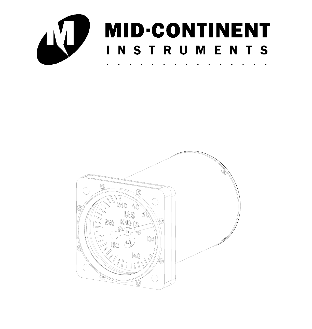
INSTALLATION MANUAL AND
OPERATING INSTRUCTIONS
MD25-( ) Series
Airspeed Indicator
REV. B May 31, 2010 MANUAL NUMBER 9017051
Page 2
REVISION DETAIL
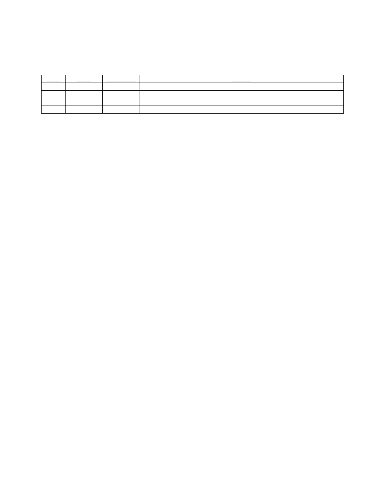
Date Approved Detail
Rev.
A 03/17/10 CJM/BAW Initial release.
B 05/31/10 BAW/MKN Update DO-160 qualification to include helicopter vibration compliance.
Update Section 2.2 to include air fitting part number.
REV. B May 31, 2010 3 Manual Number 9017051
Page 3

TABLE OF CONTENTS
SECTION 1 GENERAL DESCRIPTION
1.1 INTRODUCTION
1.2 TECHNICAL SPECIFICATIONS
1.2.1 PHYSICAL ATTRIBUTES
1.2.2 QUALIFICATIONS
SECTION 2 INSTALLATION PROCEDURE
2.1 GENERAL INFORMATION
2.2 UNPACKING AND INSPECTING
2.3 INSTALLATION
SECTION 3 OPERATION
3.1 MINIMUM PERFORMANCE REQUIREMENTS
3.1.1 SCALE ERROR
3.1.2 FRICTION / BALANCE ERROR
3.1.3 LEAKAGE
SECTION 4 CONFORMANCE
4.1 CONTINUED AIRWORTHINESS STATEMENT
4.2 ENVIRONMENTAL QUALIFICATION STATEMENT
NUMBER LIST OF TABLES AND FIGURES
1.1 PHYSICAL ATTRIBUTES TABLE
1.2 QUALIFICATION TABLE
3.1 MD25 OUTLINE DRAWING
3.2 PANEL CUTOUT DIMENSIONS
3.3 MD25 REAR VIEW
REV. B May 31, 2010 4 Manual Number 9017051
Page 4
SECTION 1 GENERAL DESCRIPTION
1.1 INTRODUCTION
The model MD25 series two-inch Airspeed Indicator is a Type A, air-driven, direct reading, self contained
airspeed indicator built to meet or exceed SAE AS8019 standards as per FAA TSO-C2d.
1.2 TECHNICAL SPECIFICATIONS
1.2.1 PHYSICAL ATTRIBUTES
Characteristics:
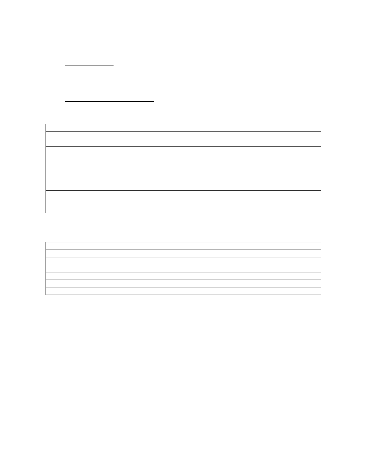
Weight: 0.6 pounds max
Dimensions: See outline drawing
Colors: Dial background is black #37038 per FED-STD-595
Markings are white #37875 per FED-STD-595
Pointer is white with black hub and counterweight
Case and bezel are black
Range markings per customer specifications
Connections: 1/8-27 NPT per MIL-P-7105
Mounting: Rear mount, see panel cutout
Lighting: Field replaceable light tray available for 5, 14, & 28VDC input
with incandescent bulbs or white LEDs
Table 1.1
1.2.2 QUALIFICATIONS
Specifications:
Qualification: FAA TSO-C2d
Environmental Qualification: RTCA DO-160F Env. Cat.
(D1)CAB[(SM)(UG)]XXXXXXYXXXXXXXXX
Altitude: -15,000 ft to +50,000 ft
Operating Temperature: -20°C to +55°C (-4°F to +131°F)
Storage Temperature: -55°C to +85°C (-67°F to +185°F)
Table 1.2
REV. B May 31, 2010 5 Manual Number 9017051
Page 5

SECTION 2 INSTALLATION PROCEDURE
2.1 GENERAL INFORMATION
This section contains mounting dimensions and other information pertaining to the installation of the
MD25 Airspeed Indicator.
2.2 UNPACKING AND INSPECTING EQUIPMENT
When unpacking this equipment, make a visual inspection for evidence of any damage that may have
incurred during shipment. The following parts should be included:
a. Airspeed Indicator – MCI P/N MD25-( )
b. Installation Manual – MCI P/N 9017051
Required equipment not provided:
a. Mounting Hardware – four (4) #6-32 screws
#6 lock washers (optional)
b. Air fittings – two (2): 1/8-27 NPT x 1/8” tube fitting
AN816-4D or similar
(MCI P/N NY-400-1-2)
Optional equipment available:
a. Light tray (LED) – MCI P/N MD31, -4, -6 (28, 14, 5V)
b. Light tray (incandescent) – MCI P/N 6015358-2 (28V)
MCI P/N 6015010-2 (14V)
MCI P/N 6018634-2 (5V)
c. Tinnerman nuts (4) – MCI P/N 6013031
2.3 INSTALLATION
Install the MD25 Airspeed Indicator within the aircraft in accordance with the aircraft manufacturer’s
instructions and the following steps:
A. Ensure the available instrument panel cutout meets the requirements of the indicator . See Fig 3.2
for details.
B. Secure the indicator to the instrument panel using the screw sizes called out in the mounting
instructions. Length of screws will be determined by aircraft instrument panel thickness. The
aircraft manufacturer or the installation facility is responsible for supplying appropriate installation
hardware.
C. Connect pitot line tube to the differential pressure port (designated “P”) on the back of the
indicator.
CAUTION: INSTALL FITTINGS IN PORTS WITH NO MORE THAN 45 IN-LBS OF TORQUE. IF
TORQUE IS NOT SUFFICIENT TO MAINTAIN A SEAL THREAD SEALANT MUST BE USED.
D. The remaining port (designated “S”) should be connected to the static line vented to atmospheric
pressure. See Fig 3.3 for details.
E. For units with light tray, connect wires to the appropriate voltage designated on the tray itself.
REV. B May 31, 2010 6 Manual Number 9017051
Page 6
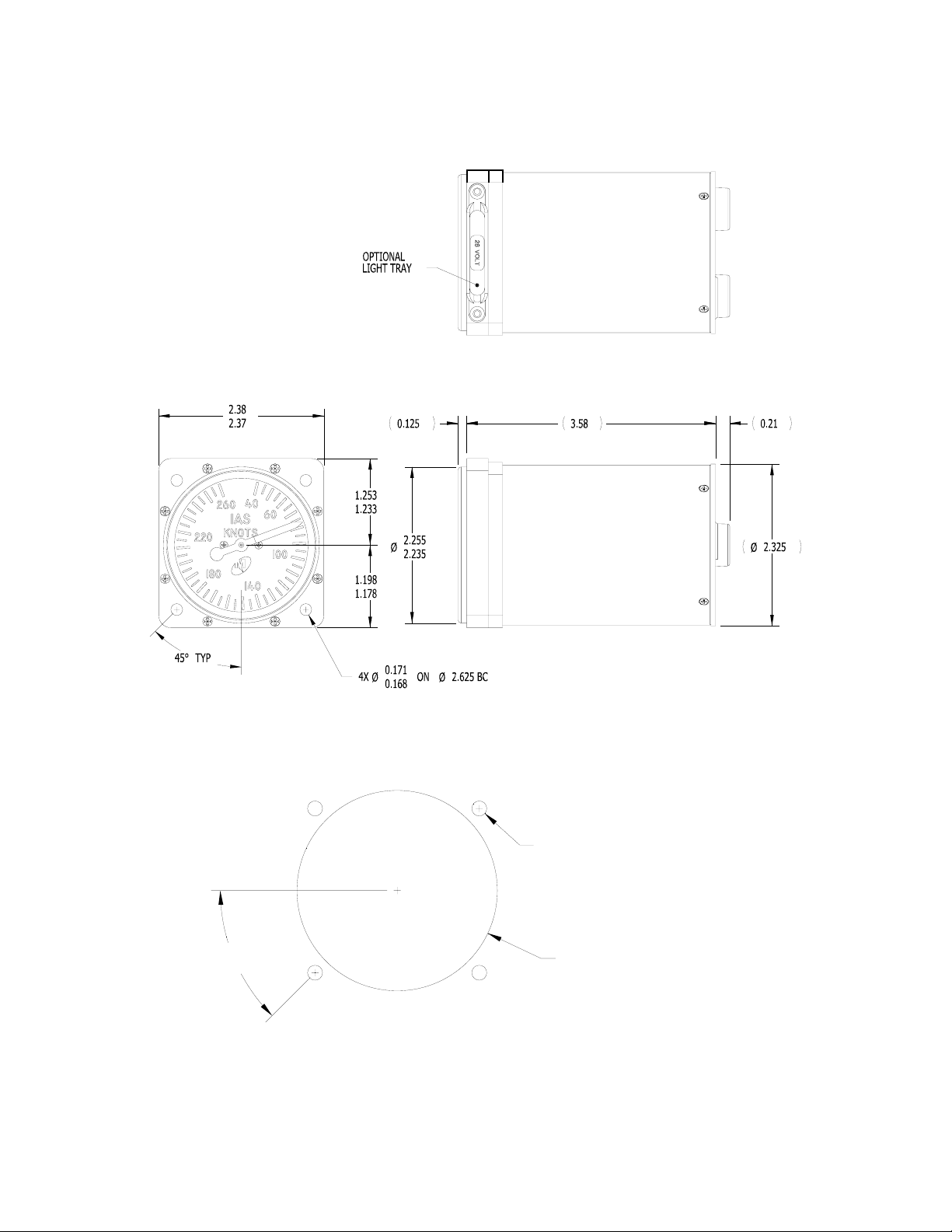
FIGURE 3.1
MD25 OUTLINE DRAWING
0.172
4X
0.168
45°TYP
FIGURE 3.2
PANEL CUTOUT DIMENSIONS
Ø
ON Ø2.625 BC
2.270
2.260
REV. B May 31, 2010 7 Manual Number 9017051
Page 7
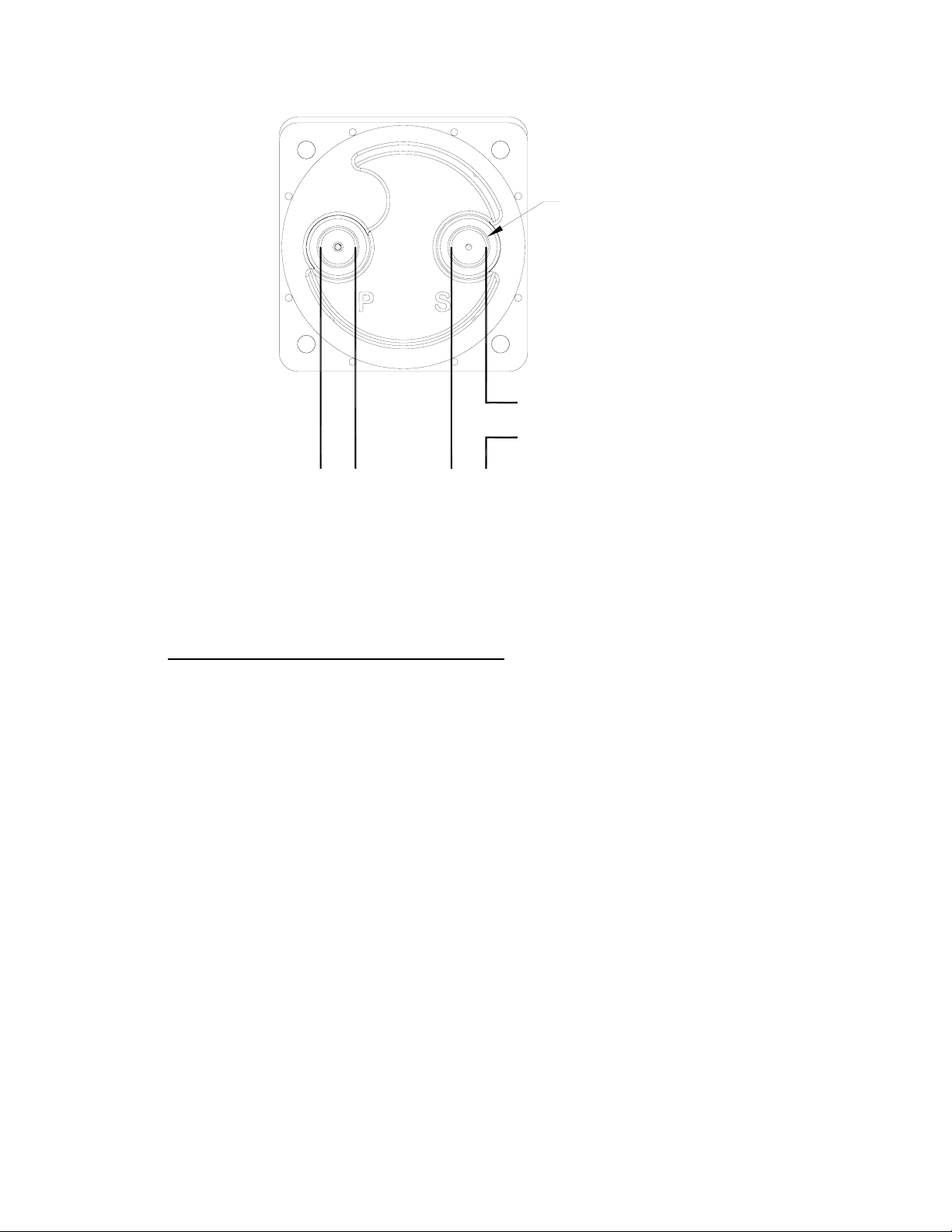
1/8-27 NPT
TO ALTIMETER AND
RATE OF CLIMB
TO STATIC LINETO PITOT LINE
FIGURE 3.3
MD25 REAR VIEW
SECTION 3 OPERATION
3.1 MINIMUM PERFORMANCE REQUIREMENTS
The MD25 Airspeed Indicator shall meet these minimum performance requirements under standard test
conditions.
3.1.1 SCALE ERROR
±5 from 20-60 Knots
±4 from 70-90 Knots
±3 from 100-160 Knots
±5 from 180-350 Knots
3.1.2 FRICTION/BALANCE ERROR
±3 from 40-180 Knots
±5 from 190-350 Knots
3.1.3 LEAKAGE
<0.05 In Hg in 1 min. under 15 In Hg Suction
<1 Knot in 1 min. at Full Scale Deflection
REV. B May 31, 2010 8 Manual Number 9017051
Page 8
SECTION 4 CONFORMANCE
4.1 CONTINUED AIRWORTHINESS STATEMENT
No periodic scheduled maintenance or calibration is necessary for continued airworthiness of the MD25
series Airspeed Indicator. If the unit fails to perform to specifications, it must be removed and serviced by a
qualified service facility.
4.2 ENVIRONMENTAL QUALIFICATION STATEMENT
NOMENCLATURE: Airspeed Indicator
MODEL NUMBER: MD25-( )
MANUFACTURERS SPECIFICATIONS: Minimum Performance Specifications:
Test Specification (TS) 349, Test Data Sheet (TDS) 349
QUALIFICATION STANDARD: RTCA DO-160F
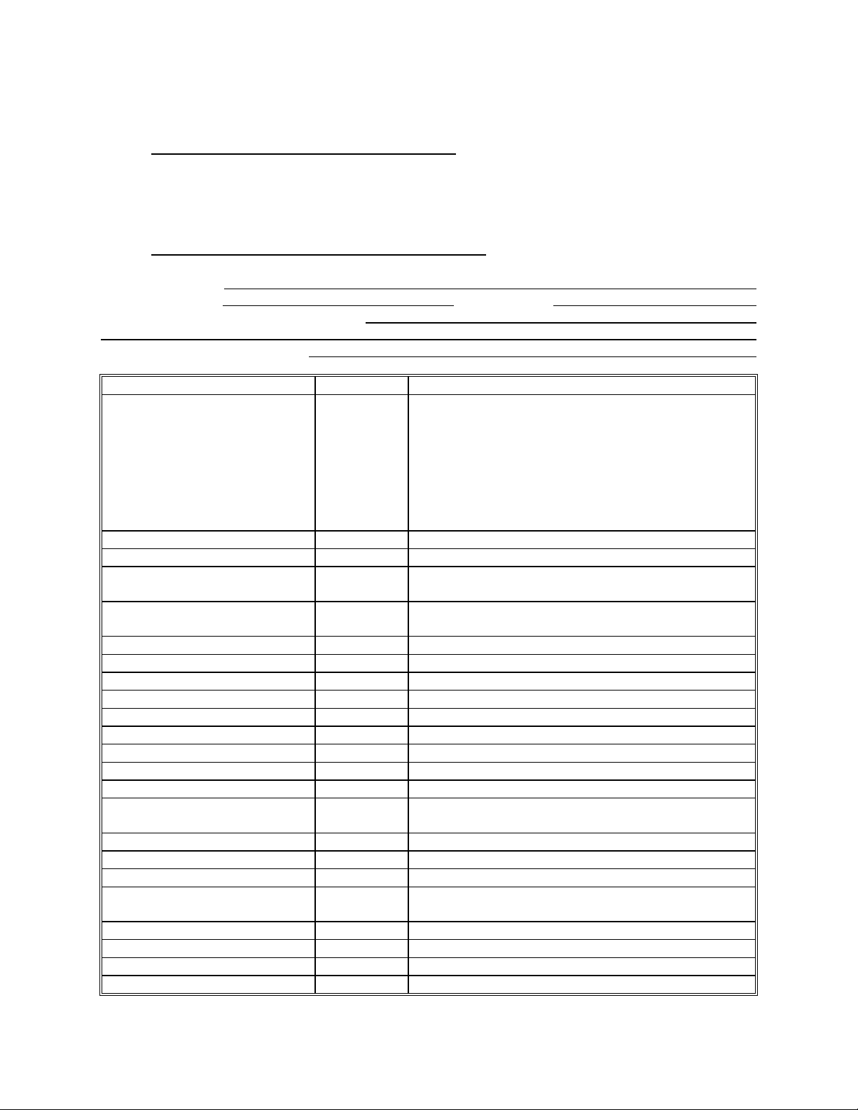
CONDITIONS SECTION DESCRIPTION OF TEST
Temperature and Altitude
Ground Survival Low
Operating Low
Ground Survival High
Operating High
Altitude
Decompression
Overpressure
Temperature Variation 5 Category C
Humidity 6 Category A
Operational Shock and
Crash Safety
Vibration 8 Category S, Curve M
Explosion 9 Category X
Waterproofness 10 Category X
Fluids 11 Category X
Sand and Dust 12 Category X
Fungus 13 Category X
Salt Spray 14 Category X
Magnetic Effect 15 Category Y
Power Input 16 Category X
Voltage Spike 17 Category X
Audio Frequency Conducted
Susceptibility
Induced Signal Susceptibility 19 Category X
Radio Frequency Susceptibility 20 Category X
Emission of Radio Freq Energy 21 Category X
Lightning Induced Transient
Susceptibility
Lightning Direct Effects 23 Category X
Icing 24 Category X
ESD 25 Category X
Flammability 26 Category X
4
4.5.1
4.5.2
4.5.3
4.5.4
4.6.1
4.6.2
4.6.3
7 Category B
18 Category X
22 Category X
TSO NUMBER: C2d
Category D1
-55C
-20C
+85C
+55C
+50,000 ft
+50,000 ft
-15,000 ft
Category U, Curve G
REV. B May 31, 2010 9 Manual Number 9017051
 Loading...