

Page 1

INSTALLATION MANUAL AND
OPERATING INSTRUCTIONS
MD222-( ) SERIES
TWO-INCH
COURSE DEVIATION INDICATOR
Page 2

ECO Rev. Date Detail
A Initial Release.
B 8/18/06 Glideslope and Nav warning indication method changed.
Annunciations were added. Connector pin-out and outline
drawings were revised.
4840 C 5/11/07 Update the DO-160 Qualification Form in the Appendix.
Revise equipment limitation section 1.2.5. Change model
number to MD222-( ).
4891 D 8/7/07 Added input voltage range notes to sections 1.2.3.2, 1.2.3.3,
1.25 and 3.4.
MANUAL Page 2 of 14 REV. D Aug. 7, 2007
Page 3

TABLE OF CONTENTS
SECTION 1 GENERAL DESCRIPTION
1.1 INTRODUCTION
1.2 TECHNICAL SPECIFICATIONS
1.2.1 PHYSICAL CHARACTERISTICS
1.2.2 ENVIRONMENTAL CHARACTERISTICS
1.2.3 ELECTRICAL CHARACTERISTICS
1.2.4 INTERFACE
1.2.5 EQUIPMENT LIMITATIONS
1.2.6 MAJOR COMPONENTS
SECTION 2 INSTALLATION CONSIDERATIONS
2.1 COOLING
2.2 EQUIPMENT LOCATION
2.3 ROUTING OF CABLES
SECTION 3 INSTALLATION PROCEDURE
3.1 GENERAL INFORMATION
3.2 UNPACKING AND INSPECTING
3.3 MOUNTING THE MD222-( )
3.4 INSTALLATION LIMITATIONS
SECTION 4 POST INSTALLATION CHECK
4.1 PRE-INSTALLATION TESTS
4.2 DIMMING ADJUSTMENT
4.3 OPERATING INSTRUCTIONS
4.3.1 VOR OPERATION
4.3.2 LOCALIZER OPERATION
4.2.3 GLIDESLOPE OPERATION
SECTION 5 INSTRUCTIONS FOR CONTINUED AIRWORTHINESS
FIGURE NO. LIST OF ILLUSTRATIONS
3-1 MATING CONNECTOR
3-2 MD222-( ) WIRING DIAGRAMS
3-3 CUTOUT DIMENSIONS FOR PANEL MOUNTING
3-4 MD222-( ) OUTLINE DRAWINGS
APPENDIX ENVIRONMENTAL QUALIFICATION FORM
MANUAL Page 3 of 14 REV. D Aug. 7, 2007
Page 4

SECTION 1 GENERAL DESCRIPTION
1.1 INTRODUCTION
The Mid-Continent Instruments MD222-( ) two-inch Course Deviation Indicators (CDI)
are designed to operate with VHF and GPS navigational equipment to provide OMNI
(VOR), GPS, LOCALIZER (LOC), and Glideslope (GS) information.
The MD222-402 and 502 are designed to accept DC Left-Right, To-From and Nav valid
signals from a GPS receiver or remote mounted VOR converter. Additionally, the
MD222-406 and 506 will accept DC signals from a glideslope or VNAV converter that
will drive the UP-DOWN needle along with accepting a vertical deviation valid signal.
The MD222-402 and 406 incorporate NAV, GPS and VLOC annunciations. The MD222502 and -506 incorporate NAV, GPS, and BC annunciations.
When GPS is selected for display, the MD222-( ) receives inputs from compatible
GPS/navigation receivers or Flight Management Systems to provide a visual presentation
to the pilot. All information presented on the navigation indicator is generated from this
external receiver.
True synchro course resolver is ORZ zeroed to industry standard 300 degrees. All units
are compatible with 5, 14 or 28 volt lighting systems.
NOTE: The MD222-( ) does not contain NAV or Glideslope warning flags. During
an invalid signal condition, the appropriate vertical or horizontal meter pointer will
stow to an out-of–view position.
1.2 TECHNICAL SPECIFICATIONS
1.2.1 PHYSICAL CHARACTERISTICS
Width: 2.4 Inches max
Height: 2.4 Inches max
Depth: 3.4 Inches max
Weight: 0.6 lbs.
Mounting: Panel
1.2.2 ENVIRONMENTAL CHARACTERISTICS
TSO Compliance: TSO C34e, C36e, C40c
Applicable Documents: RTCA DO-160E, DO-192,
DO-195, DO-196
Environmental Category:
F1S2AER(BB1G)XXXXXXZAAZ[ZC][WR]M[A3C3X]XXAX
Operating Temperature Range: -20°C to +70°C
Humidity: 95% Non-Condensing
Altitude Range: 0 to 55,000 ft.
MANUAL P/N 9016311 Page 4 of 14 REV. D Aug. 7, 2007
Page 5

1.2.3 ELECTRICAL CHARACTERISTICS
1.2.3.1 POWER
OPERATING VOLTAGE: 10-32 VDC
OPERATING CURRENT: 0.30 Amps
1.2.3.2 VOR/LOC/GPS
OBS RESOLVER: Electrical zero: 300 degrees, ORZ
DEVIATION: Input impedance: 1K ohms ±10%.
Deflection sensitivity:
150mV ±10% for full-scale
deflection
Input range (common
mode/reference): 1.0 to 5.0 volts
VALID SIGNAL: Input impedance: 1K ohms ±10%
Pointer out of view:
<125mV ±10%
Pointer in view:
260mV ±10% max
Input range (common
mode/reference): 0 to 5.0 volts
TO/FROM LED INDICATOR: Impedance: 200 ohms ±10%
Indication: ±40mV ±15%
Input range (common
mode/reference): 0 to 5.0 volts
MANUAL Page 5 of 14 REV. D Aug. 7, 2007
Page 6

1.2.3.3 GLIDESLOPE: (MD222-406 and 506 only)
1.2.4 INTERFACE:
NAV/LOC/GPS: Displays valid lateral deviation
GLIDESLOPE: Displays valid GS up-down
OBS KNOB: Used to select appropriate
MISCELLANEOUS: Provides OBS resolver
DEVIATION: Input Impedance: 1K ohms ±10%
Deflection sensitivity:
150mV ±10% for full-scale
deflection
Input range (common
mode/reference): 1.0 to 5.0 volts
VALID SIGNAL: Input Impedance: 1K ohms ±10%
Pointer out of view:
<125mV ±10%
Pointer in view:
260mV ± 10% max
Input range (common
mode/reference): 0 to 5.0 volts
with signal inputs and TO/FROM
information from the GPS/NAV
receiver.
information from the glideslope
receiver.
inbound or outbound bearing to a
VOR station or GPS waypoint.
information to a GPS/NAV
receiver. Provides annunciation of
NAV, VLOC, BC (if applicable)
and GPS selections.
MANUAL Page 6 of 14 REV. D Aug. 7, 2007
Page 7

1.2.5 EQUIPMENT LIMITATIONS
REQUIREMENTS FOR VOR/ILS SYSTEM:
1. The navigation receiver shall be certified to the standards of TSO
C40a/b/c or TSO C36c/d/e.
REQUIREMENTS FOR GLIDESLOPE SYSTEM:
1. The glideslope receiver/converter shall be certified to the standards of
TSO C34c/d/e.
2. The centering error as presented to the pilot shall not exceed 13% of
standard deflection with a 95% probability under all combinations of
the service conditions listed in RTCA document DO-192.
3. Deviation current with a 700μV standard glideslope deviation signal
applied to the receiver input shall be 78μA ±10% into a 1000 ohm
load. Deviation current shall not change more than 15% as the RF
level of a standard glideslope deviation signal is varied from 100 to
10,000μA. Deviation current shall be proportional within 5% to the
difference in depth of modulation of the 90Hz and 150Hz tones.
4. Warning signal output shall be a DC current less than 125μA into a
1000-ohm load for a warning indication. Warning signal for a fully
negated warning shall be a DC current of 260μA minimum into a
1000-ohm load.
Note the MD222 input voltage range limitations in sections 1.2.3.2 and 1.2.3.3 above and
verify that connected navigation equipment’s outputs are within those ranges.
1.2.6 MAJOR COMPONENTS
This indicating system is comprised of one major component, the MD222-( ) Course
Deviation Indicator.
MANUAL Page 7 of 14 REV. D Aug. 7, 2007
Page 8

SECTION 2 INSTALLATION CONSIDERATIONS
2.1 COOLING
No direct cooling is required. As with any electronic equipment, overall reliability may
be increased if the MD222-( ) is not located near any high heat source or crowded next to
other equipment.
2.2 EQUIPMENT LOCATION
The MD222-( ) course deviation indicator must be mounted as close to the pilot’s field of
view as possible. Since this is a panel-mounted instrument, the unit depth, with connector
attached, must also be taken into consideration.
2.3 ROUTING OF CABLES
Care must be taken not to bundle the MD222-( ) logic and low-level signal lines with any
high-energy sources. Examples of these sources include 400 HZ AC, Comm., DME, HF
and transponder transmitter coaxial cables. Always use shielded wire as shown on the
installation print. Avoid sharp bends in cabling. Avoid routing near aircraft control
cables.
MANUAL Page 8 of 14 REV. D Aug. 7, 2007
Page 9

SECTION 3 INSTALLATION PROCEDURES
3.1 GENERAL INFORMATION
This section contains interconnect diagrams, mounting dimensions and other information
pertaining to the installation of the MD222-( ). After installation of cabling and before
installation of the equipment, ensure that power is applied only to the pins specified in
the interconnect diagram.
3.2 UNPACKING AND INSPECTING EQUIPMENT
When unpacking equipment, make a visual inspection for evidence of damage incurred
during shipment. The following parts should be included:
1. MD222-( ) Series course Deviation Indicator
2. Connector Kit (25 pin): MCI P/N 7014517
3. Installation Manual: MCI P/N 9016311
3.3 MOUNTING THE MD222-( ) INDICATOR
The MD222-( ) course deviation indicator should be mounted as close to the pilot’s field
of view as possible. Avoid mounting close to heater vents or other high heat sources.
Allow a clearance of at least 3 inches from the back of unit for connector removal.
The MD222-( ) is to be secured in place behind the panel since it is designed for rear
mount only. Make a panel cutout as shown in Figure 3.3. Secure the indicator in place
with three 6-32 x 1.0” (max) flat head Phillips screws.
3.4 INSTALLATION LIMITATIONS
Wire the aircraft harness according to the appropriate figure. Use 24 AWG or larger wire
for all connections. You MUST use shielded wire where shown by the radio
manufacturer. Avoid sharp bends and routing cable near high-energy sources. Care must
be taken to tie the harness away from aircraft controls and cables.
Note the MD222-( ) input voltage range limitations in sections 1.2.3.2 and 1.2.3.3 above
and verify that connected navigation equipment’s outputs are within those ranges.
MANUAL P/N Page 9 of 14 REV. D Aug. 7, 2007
Page 10
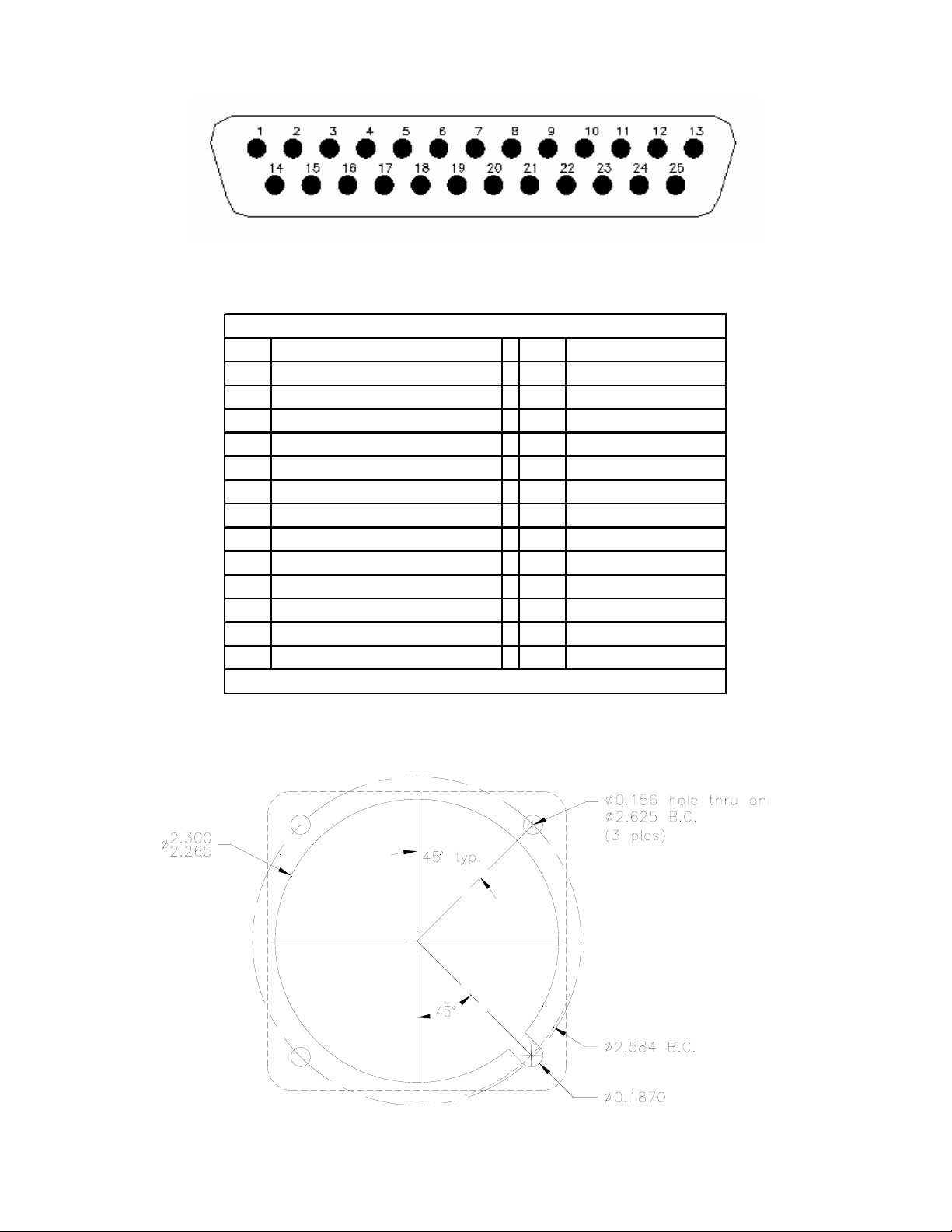
FIGURE 3-1 REAR VIEW OF MATING CONNECTOR
Connector Pin Out
Pin # Pin #
1 OBS Rotor H 14 NAV Annunciation
2 OBS Rotor C 15 GPS Annunciation
3OBS Stator D 16+To
4 OBS Stator G 17 +From
5OBS Stator E 18+GS Warning*
6OBS Stator F 19-GS Warning*
7 Reserved 20 +NAV Warning
8 VLOC (or BC) Annunciation 21 -NAV Warning
9 +5 VDC Lighting 22 +Left
10 +14 VDC Lighting 23 +RT
11 +28 VDC Lighting 24 +Down*
12 10-32 Vdc Power 25 +Up*
13 Power/Lighting Ground
* Applicable on MD222-406/506 only
FIGURE 3-2 WIRING DIAGRAM, MD222-( )
FIGURE 3-3 CUTOUT DIMENSIONS FOR PANEL MOUNTING
MANUAL Page 10 of 14 REV. D Aug. 7, 2007
Page 11
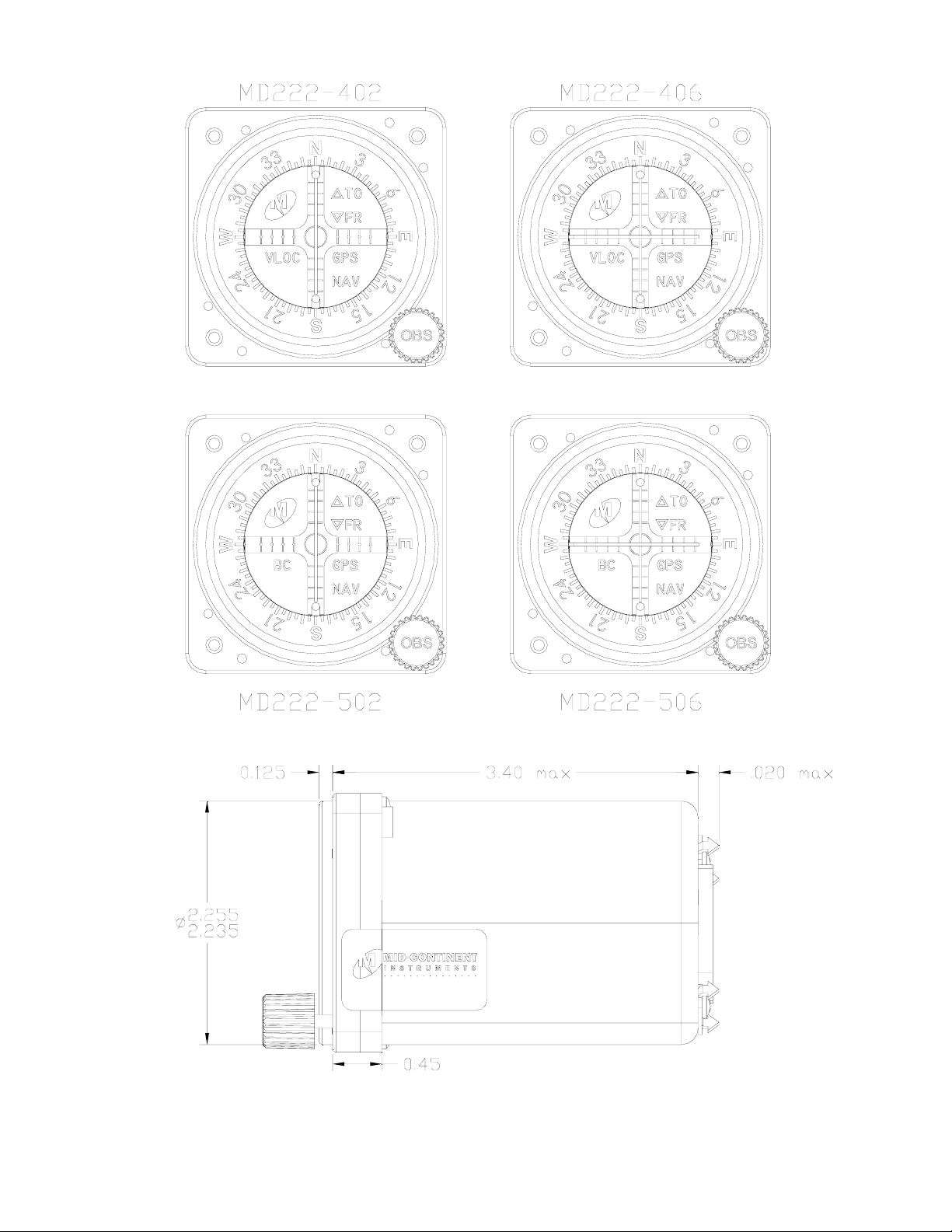
FIGURE 3-4 OUTLINE DRAWINGS
MANUAL Page 11 of 14 REV. D Aug. 7, 2007
Page 12

SECTION 4 POST INSTALLATION CHECK
4.1 PRE-INSTALLATION TESTS
With the MD222-( ) indicator disconnected, turn on the avionics master switch and verify
that aircraft power on connector pin 12 is 14 VDC or 28 VDC. Using an ohmmeter,
verify pin 13 is aircraft ground.
4.2 DIMMING ADJUSTMENT
During installation of the MD222-( ) course deviation indicator, check the brightness of
the GPS, NAV, BC (if applicable) and VLOC annunciations as well as the compass ring.
The ambient and aircraft panel lighting levels should be set to simulate minimum light
operations and the annunciators should be useable and consistent with other cockpit
lighting. If required, the dimming adjustment is located on the back of the MD222-( ) unit
and is labeled “DIM ADJ”.
4.3 OPERATING INSTRUCTIONS
All controls required to operate the MD222-( ) course deviation indicator are located on
the front of the unit and on the front panel of the related navigation receiver.
4.3.1 VOR OPERATION
Channel the NAV receiver to the desired VOR frequency and positively
identify the station by listening to received audio. This signal is valid if
the vertical pointer is in view.
Flying inbound to a VOR station is accomplished by first rotating the OBS
knob to center the deviation indicator. Next, determine that the TO
condition is illuminated on the TO-FROM indication. The aircraft is then
turned to a magnetic heading, which is the same as the selected course
with proper allowance for wind correction. When the aircraft is on course,
the vertical pointer will be centered. If the aircraft moves off course, the
deviation indicator will move away from the center position and flying in
the direction of pointer deflection (left or right) is required to re-intercept
the course.
The procedure for flying outbound from a VOR station is the same as
flying inbound, except the OBS knob is first rotated to cause a “FROM”
indication to appear with the pointer centered.
To intercept a selected VOR radial (from the station) and fly outbound,
turn the OBS control to set the desired radial under the top indicator index.
Maneuver the aircraft to fly the selected radial magnetic heading plus 45°
intercept angle that will provide a sufficient intercept angle. The intercept
angle should be reduced as the deviation needle approaches an on course
condition (center) to prevent excessive course bracketing.
MANUAL Page 12 of 14 REV. D Aug. 7, 2007
Page 13
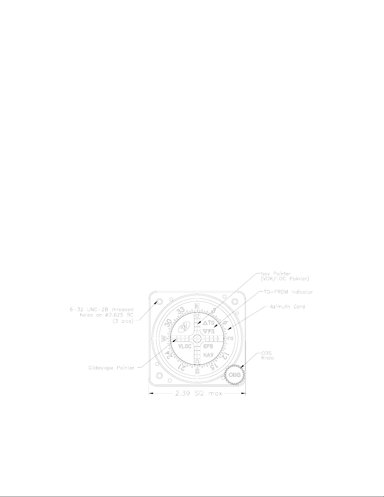
4.3.2 LOCALIZER OPERATION
Select the desired localizer frequency and observe that the vertical pointer
is in view indicating a valid condition. The TO-FROM indication is not
functional for localizer operation. When flying on the front course, or
outbound on the back course, make corrections toward the localizer
(vertical) needle deflection. The localizer path narrows as the approach
end of the runway becomes closer. When flying inbound on the back
course or outbound on the front course, the corrections are made away
from the direction of needle deflection. A helpful hint when flying the
localizer is to set the localizer heading on the OBS dial under the lubber
line for quick reference.
4.3.3 GLIDESLOPE OPERATION
The glideslope (horizontal) needle provides the pilot with vertical steering
information during ILS approaches. The glideslope circuitry is energized
when the associated localizer frequency is selected on the navigation
receiver. Observe that the horizontal pointer is in view. The glideslope
needle deflects towards the direction the pilot must fly to remain on the
glide path.
If the glideslope needle deflects upward, the aircraft is below the glide
path and the pilot must climb to again intercept the glide path and center
the needle. If the needle deflects downward the aircraft is above the glide
path and the pilot must descend to again intercept the glide path and center
the needle. When the needle is centered the aircraft is on the glide path.
SECTION 5 INSTRUCTIONS FOR CONTINUED AIRWORTHINESS
Mid-Continent Instrument Company Inc. products are designed and manufactured to
allow “on condition maintenance”, defined as no maintenance required until equipment
does not properly perform its intended function. If service is required, Mid-Continent
Instrument Company should complete a performance test.
MANUAL Page 13 of 14 REV. D Aug. 7, 2007
Page 14

ENVIRONMENTAL QUALIFICATION FORM
RTCA / DO160E
NOMENCLATURE: MD222-( ) COURSE DEVIATION INDICATOR
MODEL NO: MD222-( ) TSO NO: C34e, C36e, C40c
MANUFACTURER TEST SPECIFICATION: TS240
MANUFACTURER: MID-CONTINENT INSTRUMENT CO., INC.
x
Conditions Section Description of Tests
Temperature and Altitude
Survival Low Temperature
Operating Low Temperature
Temperature Variation 5.3 Equipment tested to Category S2
Humidity 6.0 Equipment tested to Category A
Operational Shocks and Crash
Safety
Vibration 8.0 Equipment tested w/o shock mounts to Category
Explosion 9.0 Equipment identified as Cat. X, no test required
Waterproofness 10.0 Equipment identified as Cat. X, no test required
Fluids Susceptibility 11.0 Equipment identified as Cat. X, no test required
Sand and Dust 12.0 Equipment identified as Cat. X, no test required
Fungus 13.0 Equipment identified as Cat. X, no test required
Magnetic Effect 15.0 Equipment tested to Category Z
Power Input 16.0 Equipment tested to Category A
Voltage Spike 17.0 Equipment tested to Category A
Audio Frequency
Susceptibility
Induced Signal Susceptibility 19.0 Equipment tested to Category ZC
Radio Frequency
Susceptibility
Radio Frequency Emissions 21.0 Equipment tested to Category M
Lightning Induced Transient
Susceptibility
Lightning Direct Effects 23.0 Equipment identified as Cat. X, no test required
Icing 24.0 Equipment identified as Cat. X, no test required
Electrostatic Discharge (ESD) 25.0 Equipment tested to Category A
Fire, Flammability 26.0 Equipment identified as Cat. X, no test required
4.0
4.5.2
4.5.2
Equipment tested to Categories F1
Survival Low Temp=-55°C
Operating Low Temp=-20°C
7.0 Equipment tested to Category E
(Type 5, Fixed-Wing and Helicopter)
R, curves B, B1, G
18.0 Equipment tested to Category Z
20.0 Tested for conducted susceptibility to Category W
Tested for radiated susceptibility to Category R
22.0 Equipment tested to
Pin Test: Waveform A, Level 3
Cable Bundle: Waveform C
Single/Multiple Stroke Level 3
Multiple Burst no test performed (X)
[A3C3X]
MANUAL Page 14 of 14 REV. D Aug. 7, 2007
 Loading...