

Page 1
ManualNumber
9018205
RevisionG
May20,2021
Page 2
FOREWORD
This manual provides information intended for use by persons who, in accordance with current
regulatory requirements, are qualified to install this equipment. If further information is required,
please contact:
Mid-Continent Instruments and Avionics
Attn: Customer Service Dept.
9400 E. 34th Street N.
Wichita, KS 67226 USA
PH (316) 630-0101
FX (316) 630-0723
www.mcico.com
We welcome your comments concerning this manual. Although every effort has been made to
keep it free of errors, some may occur. When reporting a specific problem, please describe it
briefly and include the manual part number, the paragraph/figure/table reference and the page
number. Send your comments to:
Mid-Continent Instruments and Avionics
Attn: Technical Publications
9400 E. 34th Street N.
Wichita, KS 67226 USA
PH (316) 630-0101
FX (316) 630-0723
All products produced by Mid-Continent Instrument Co., Inc., including those identified as
Mid-Continent Instruments and Avionics or True Blue Power, are designed and manufactured
in Wichita, KS, USA.
Mid-Continent Instrument Co., Inc.
Download the current
version of this installation
manual using your
smartphone or tablet.
© Copyright 2018
Manual Number 9018205 Revision G, May 20, 2021 1
Page 3
TABLE OF CONTENTS
SECTION 1 GENERAL DESCRIPTION 4
1.1 INTRODUCTION 4
1.2 PHYSICAL
1.3 MODEL
1.4 TECHNICAL
SECTION 2 PRE-INSTALLATION CONSIDERATIONS 8
2.1 COOLING 8
2.2 EQUIPMENT
2.3 ROUTING
2.4 LIMITATIONS 8
2.5 MODIFICATION 9
ATTRIBUTES 4
AND PART NUMBER IDENTIFICATION 6
SPECIFICATIONS 6
LOCATION 8
OF CABLES 8
SECTION 3 INSTALLATION 10
3.1 GENERAL 10
3.2 PRE-INSTALLATION
INSPECTION 10
3.3 PARTS 10
3.4 CABLE
HARNESS 11
3.5 INSTALLATION 13
SECTION 4 OPERATION 14
4.1 UNIT ARCHITECTURE 14
4.2 CLOCK
4.3 USB
4.4 DIMMING
4.5 OPERATIONAL
4.6 TEMPERATURE
AND USB PROTECTIVE FEATURES 14
OPERATION 15
FUNCTIONS 15
MODES 17
PROBE INSTALLATION 28
SECTION 5 CONFORMANCE 30
5.1 INSTRUCTIONS FOR CONTINUED AIRWORTHINESS 30
5.2 ENVIRONMENTAL
QUALIFICATION STATEMENT 31
Manual Number 9018205 Revision G, May 20, 2021 2
Page 4
REVISION HISTORY
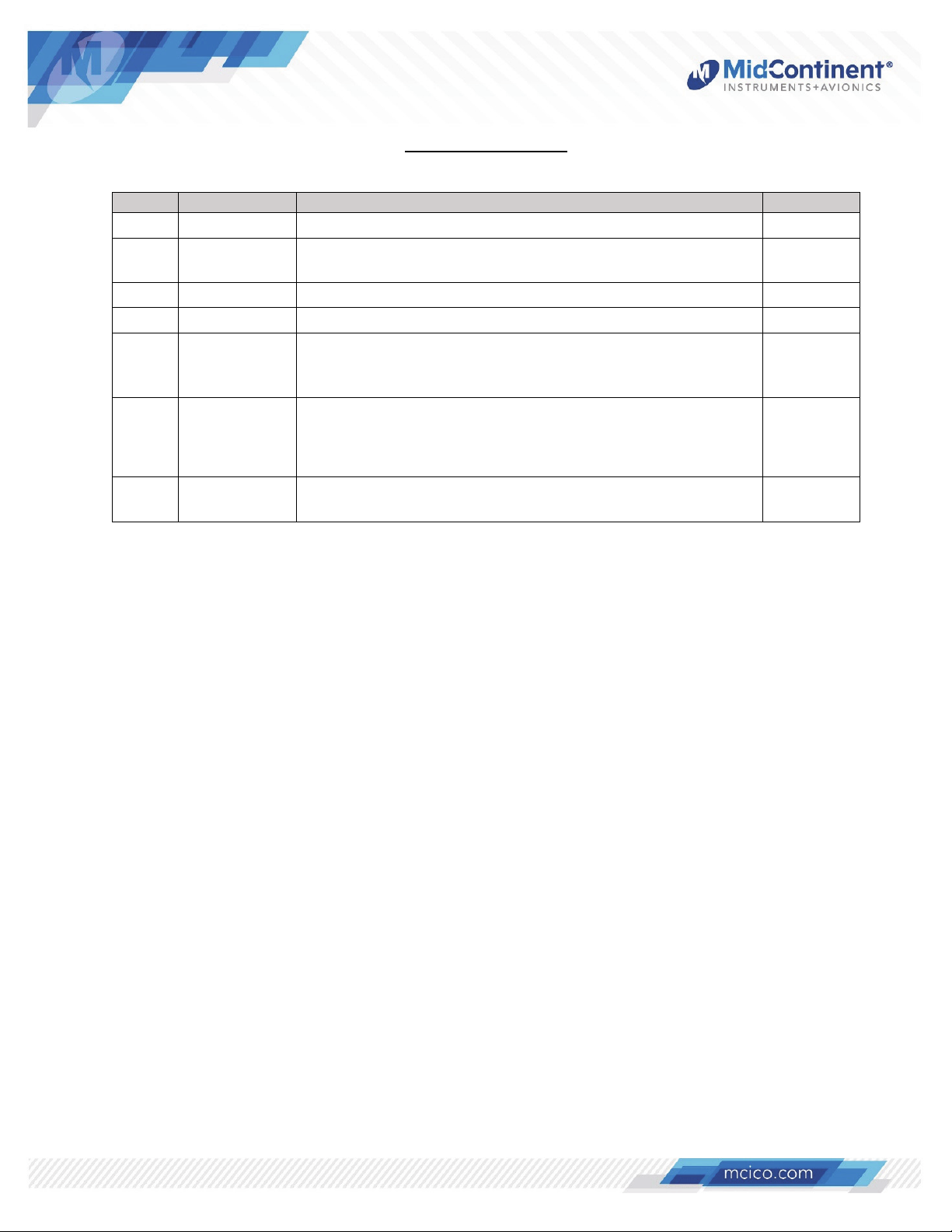
Rev Date Detail Approved
A 07/15/2014 Initial release. BAW
B 09/15/2014
Revised EQF, added DO-311A Compliance Qualification
Form and provided additional limitation details (sec 2.5)
WVC
C 03/12/2015 Added Environmental Qualification Statement to Section 6. TV
D 03/21/2016 Added Qualifications to Section 1.3. WVC
Updates for MOD 1 function enhancements. Revised
E 10/30/2018
elapsed timer to include countdown timer function. Timer
WVC
reset function operates only when timer is stopped.
Updated style and brand to meet Marketing and
F 04/01/2021
Engineering guidelines. Added -0, -3, -4 and -5 units and
temperature probe information.
DLR
Removed reference to -1 version.
G 05/20/2021
Inserted Deviation Statement in Section 2.4.
DLR
Manual Number 9018205 Revision G, May 20, 2021 3
Page 5

SECTION 1 GENERAL DESCRIPTION
1.1 INTRODUCTION
The CH93 series, part numbers 6420093-( ), is a multi-function digital clock / chronometer /
voltmeter / temperature unit with multiple options for USB Charging Ports. The unit fits into a
standard, rear-mounted, 2-¼” avionics panel cutout. Power is drawn from the aircraft main bus to
light a white, six digit, seven segment LED clock. The clock can display several different modes:
local time, universal time, flight timers, elapsed and countdown timers and optionally, bus voltage
and up to two temperature inputs. The CH93 display is daylight readable with two methods of
brightness control. It can be controlled automatically using the internal photocell or manually with
an external dimming bus voltage. The CH93 clock has an internal battery to maintain clock time
and flight timer memory when the aircraft is not in use.
The USB Charging Ports are designed as DCPs (Dedicated Charging Ports) to industry-standard
protocol per the USB Battery Charging 1.2 Compliance Plan. Some models also comply with the
higher power requirements of USB Power Delivery 2.0 and 3.0. Early-generation or smaller
consumer electronics typically accept one (1.0) amp during charging. However, newer electronics,
such as tablets and larger devices can accept, and in some cases, require up to 3 amps to charge
and operate. Unlike most dual USB chargers which provide one (1.0) amp on one port and 2.1
amps on the second port, the CH93 provides 3 amps per port. The Type A High Power (HP) USB
ports provide a 5 volt output at 3 amps and the Type C Max Power USB-PD port provides 3 amps
at 5, 9, 15, or 20 volts depending on the type and needs of the device. This provides enough
power to charge any USB device, including the higher demand products. Refer to Section 1.4 for
specific details on charging port configurations for each model. With features like short circuit
protection, over-current protection, low voltage shut-down and temperature monitoring, it handles
abnormal conditions safely.
1.2 PHYSICAL ATTRIBUTES
The CH93 is a single, integrated component contained in a metal enclosure, fitting into a standard
2 ¼” avionics instrument panel cutout. Two types of units are available within the series. Type 1
units have a 4-pin input connector on the rear of the unit for power, external dimming control and
flight timer operation. Type 2 units have a 9-pin D-shell connector that add connections for
temperature probe inputs and a countdown timer external alarm signal. The series includes
versions with and without USB charging ports, located on the front of the unit below the display,
and three control buttons for user interface: Mode, + (plus), and – (minus). The modes are
annunciated with backlit indicators for UTC, Flight, Timer, Volts, and OAT.
Refer to Figures 1.1 and 1.2 for unit dimensions.
Manual Number 9018205 Revision G, May 20, 2021 4
Page 6
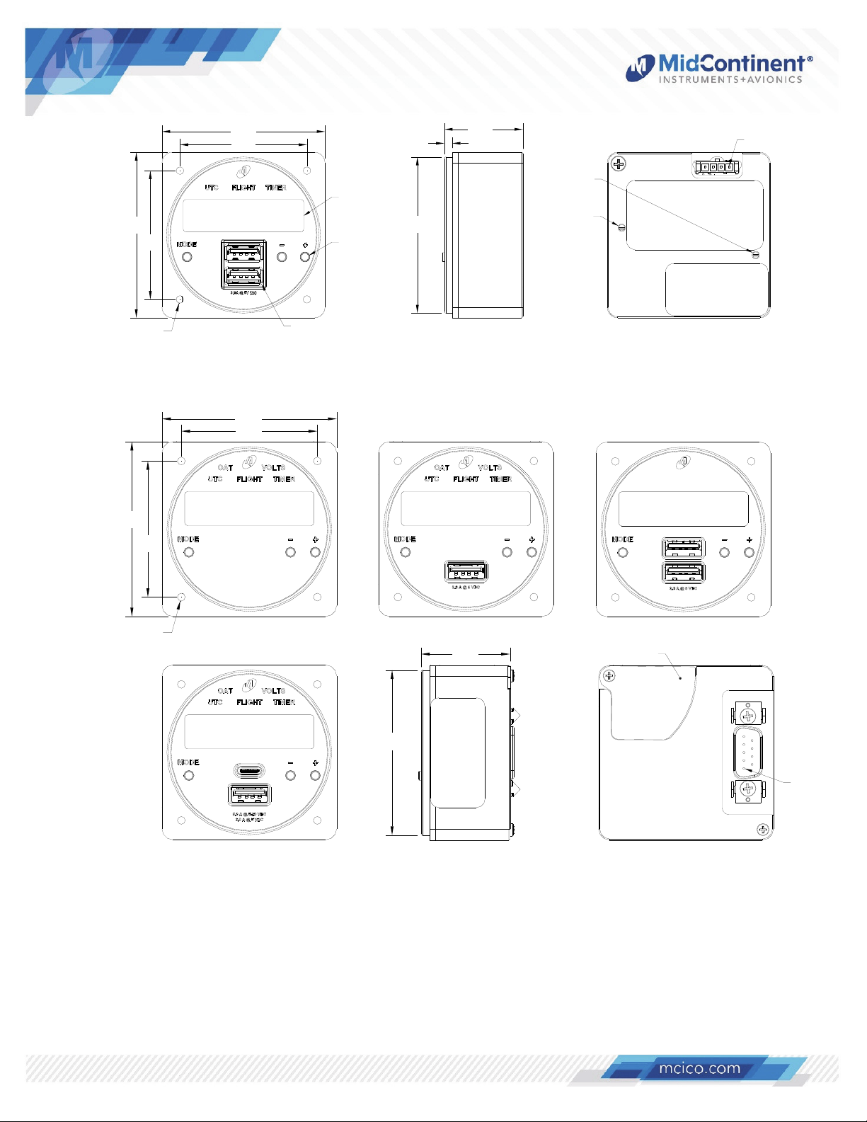
2.39
1.86
4X 6-32 UNC
2.39
2.39
1.86
2.39
1.86
6 digit display
window
Push button
operation (3x)
Dual USB
Charging Ports
CH93 Type 1 Drawing (-2 Unit)
Ø2.25 MAX
Figure 1.1
1.15
0.12
Photocell
dim adjust
Aircraft
dim adjust
Pin 1
1.86
4X 6-32 UNC
6420093-0
6420093-5
CH93 Type 2 Drawing (-0, -3, -4 and -5 Units)
Ø2.25 MAX
6420093-3
1.22
Figure 1.2
Replaceable
Coin Cell (BR2032) Cover
6420093-4
Pin 1
Manual Number 9018205 Revision G, May 20, 2021 5
Page 7
–
A
r
A
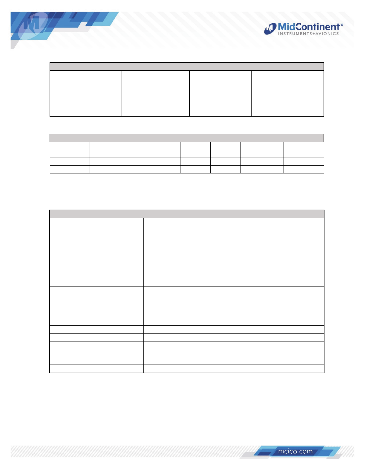
1.3 MODEL AND PART NUMBER IDENTIFICATION
Chronos Models and Type
Part Number:
6420093-0
6420093-2
6420093-3
6420093-4
6420093-5
Model:
CH93
CH93HP
CH93HP
CH93HP
CH93MAX
Type:
Table 1.1
Type 2
Type 1
Type 2
Type 2
Type 2
USB Charging Ports:
None
Dual Type A
Single Type A
Dual Type A
Type A / Type C
Feature Summary
Feature UTC
Time
Local
Time
Flight
Timers
Elapsed
Timers
Alert
Output
Volts OAT Replaceable
Type 1 Y Y Y Y N N N N
Type 2 Y Y Y Y Y Y Y Y
Table 1.2
1.4 TECHNICAL SPECIFICATIONS
Battery
Electrical Attributes
Input Voltage:
-0,-2,-3,-4:
-5:
Input Power:
-0
-2
-3
-4
-5
10 – 32 VDC
22
32 VDC
5 watts max; 0.3 amps @ 14 VDC / 0.15 amps @ 28 VDC
36 watts max; 2.6 amps @ 14 VDC / 1.3 amps @ 28 VDC
21 watts max; 1.5 amps @ 14 VDC / 0.75 amps @ 28 VDC
36 watts max; 2.6 amps @ 14 VDC / 1.3 amps @ 28 VDC
84 watts max; 3.0 amps @ 28 VDC
USB Output Voltage: Type A: 5 VDC ± 0.25 VDC per port
Type C: 5, 9, 15, or 20 VDC ±0.25 VDC per port
(auto-adjustable)
USB Output Power: 3.0 amps max per USB port
(15 watts Type A; 60 watts Type C)
Efficiency: ≈ 90% nominal
Clock Accuracy: ±15 seconds per month
Compatible Temp Probes:
RTD:
Current Sense:
500 Ω Resistor
D590 Temperature Transduce
larm output (Type 2 only): Open drain ground limited to 100mA, max 32 VDC
Table 1.3
Manual Number 9018205 Revision G, May 20, 2021 6
Page 8
A
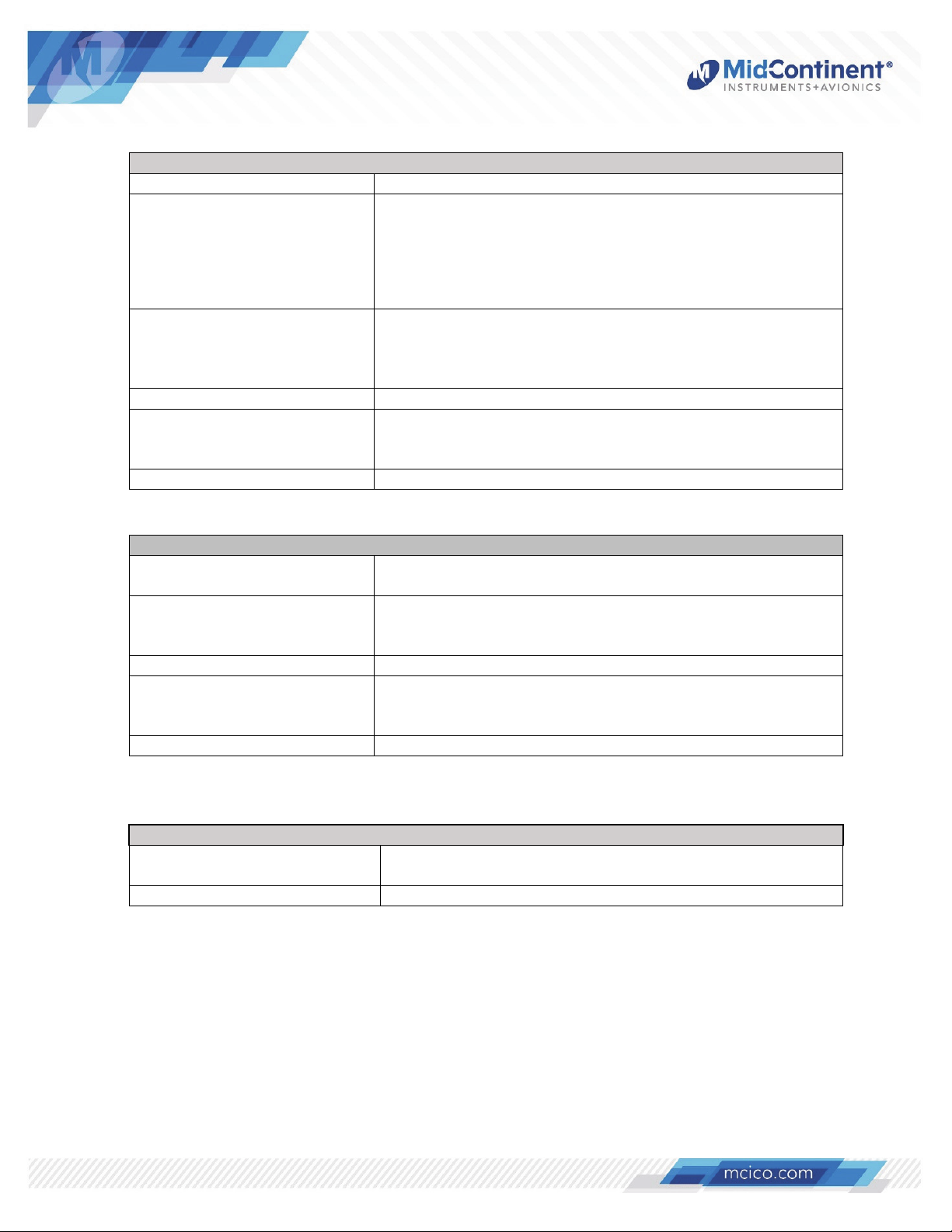
Physical Attributes
Weight: 5.0 ounces (142 g)
Dimensions
(not including connector)
Type 1
Type 2
Charging Ports Type
-0:
-2,-3,-4:
-5:
2.39 inches wide x 2.39 inches high x 1.15 inches deep
(61 mm wide x 61 mm high x 29 mm deep)
2.39 inches wide x 2.39 inches high x 1.22 inches deep
(61 mm wide x 61 mm high x 31 mm deep)
Not Applicable
Type A USB
Type
USB; Type C USB
Clock Digits: 0.360” H x 0.138” W
Connector Kit
Type 1
Type 2
MCIA P/N 9018178
MCIA P/N 9018178-1
Mounting: Rear Panel Mount
Table 1.4
Internal Battery Attributes
Type: Primary (non-rechargeable) coin cell;
poly-carbonmonofluroride lithium
Model:
Type 1
Type 2
BR2330 (factory replaceable only)
BR2032 (field replaceable)
Output Voltage: 3 VDC
Capacity / Energy:
Type 1
Type 2
0.255 Ah / 0.765Wh
0.190 Ah / 0.570Wh
Certification: UL 1642 (see section 2.4)
Table 1.5
Qualifications
Certification FAA TSO-C71
EASA ETSO-C71
Environmental Qualification RTCA/DO-160G (See Section 5.2)
Table 1.6
Manual Number 9018205 Revision G, May 20, 2021 7
Page 9

SECTION 2 PRE-INSTALLATION CONSIDERATIONS
2.1 COOLING
The CH93 will become warm when in use; however no external cooling is required. This is normal
and within operational parameters. No special mounting considerations are required, although
mounting to a metal surface can help dissipate any heat generated and extend the life of the
product.
2.2 EQUIPMENT LOCATION
The CH93 Digital Clock / USB Charging Port is designed for a circular rear panel mount
configuration, allowing for installation in a cockpit or cabin. Clearance should be provided for the
input mating connector which may require an additional inch of clearance beyond the rear of the
unit.
2.3 ROUTING OF CABLES
Avoid sharp bends in cabling and routing near aircraft control cables. Avoid close proximity and
contact with aircraft structures, avionics equipment or other obstructions that could chafe wires
during flight and cause undesirable effects.
2.4 LIMITATIONS
The conditions and tests for TSO approval of this article are minimum performance standards.
Those installing this article, on or in a specific type or class of aircraft, must determine that the
aircraft installation conditions are within the TSO standards, specification of the article and
deviations as listed above. TSO articles must have separate approval for installation in an aircraft.
The article may be installed only according to 14 CFR part 43 or the applicable airworthiness
requirements.
Note: Per 8300.16 job aid applicable to airplanes certified under Title 14 of the Code of Federal
Regulations part 25 (Section H. Alterations or Repairs, Element H.7). (Approval is required for)
Changes to designs involving lithium batteries or battery systems except for the following cases:
1. Very small batteries or battery systems (e.g., button/coin cells) not required for safe
operation of the airplane that have less than 2 watt-hours of energy and meet UL
1642,UL 2054 or International Electrotechnical Commission(IEC) 62133.
The battery in the CH93 is non-rechargeable and considered “very small”. It is less than two Watthours and is certified to UL 1642. No STC or coordination with the ACO is required.
Two items have been submitted to and approved by the FAA as deviations to the TSO certification
of the product. The 6430093-( ) series Digital Clock/USB Charger complies with TSO-C71 with the
following exceptions:
The dielectric strength requirement per paragraph 2.7 of TSO-C71 does not apply based on
the lack of traditional transformer technology used in the design.
Environmental qualifications were verified per RTCA DO-160, Revision G in lieu of those
identified within the minimum performance standards (MPS) of the TSO.
Manual Number 9018205 Revision G, May 20, 2021 8
Page 10
2.5 MODIFICATION
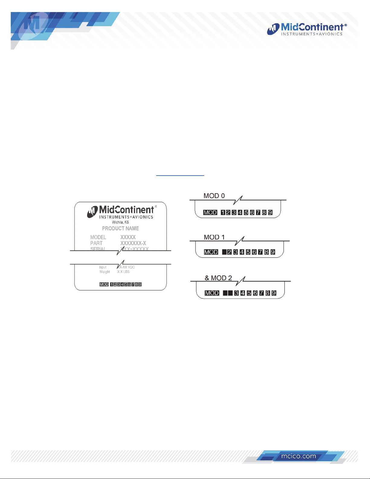
This product has a nameplate that identifies the manufacturer, part number, description,
certification(s) and technical specifications of the unit. It also includes the “MOD” or modification
number representing notable changes in the hardware design of the unit.
Modification (MOD) 0 is the initial release of the product and is identified on the nameplate by the
lack of marking on the MOD numbers 1 through 9 (i.e. 1-9 are visible). All subsequent
modifications are identified on the nameplate by the marking/blacking out of that particular MOD
number (i.e. for MOD 1, the number 1 is not visible and 2-9 are visible - see Figure 2.1 for
examples). MODs do not have to be sequentially inclusive and may be applied independent of
each other.
For additional details regarding specific changes associated with each MOD status refer to the
product published Service Bulletins at www.mcico.com.
MOD 0
MOD 1
MOD 1
& MOD 2
Figure 2.1
Nameplate and MOD Status Example
Manual Number 9018205 Revision G, May 20, 2021 9
Page 11
SECTION 3 INSTALLATION
3.1 GENERAL
This section contains interconnect diagrams, mounting dimensions and other information
pertaining to the installation of the CH93 Digital Clock / Dual USB Charging Port. After installation
of cabling and before installation of the equipment, ensure that power and ground are applied to
the proper pins specified in Section 3.4.2, Pin Assignment Information.
3.2 PRE-INSTALLATION INSPECTION
When unpacking this equipment, make a visual inspection for evidence of any damage that may
have occurred during shipment.
3.3 PARTS
Included Parts
A. Digital Clock (with USB Charging Port(s)) MCIA P/N 6420093-( )
B. Installation and Operation manual MCIA P/N 9018205
C. Installation Kit (for Type 1) MCIA P/N 9018178
Mating Connector, 4-Pin
Pins (6) (4 required, 2 spares)
Screws (5), #6-32 x 3/8” Flat Head (4 required, 1 spare)
D. Installation Kit (for Type 2) MCIA P/N 9018178-1
Mating D-Sub Connector, 9-Pin
Screws (5), #6-32 x 3/8” Flat Head (4 required, 1 spare)
Available Parts
A. 500 Ω Outside Air Temperature Probe MCIA P/N B-10-1
B. 500 Ω Cockpit/Cabin Temperature Probe MCIA P/N B-11-1
C. Current Sense Cockpit/Cabin Temperature Probe MCIA P/N B-11-2
Installer Supplied Parts
A. Cable Harness Wire, See Section 3.4.1 for specifications
B. Circuit Breaker Recommendations:
-0,-2,-3,-4 units: 3 amps (1.5 amp may be sufficient for 28V aircraft - as
needed per system requirements)
-5 units: 5 amps for 28V aircraft
C. Davtron C307PS or 655 current sense probes (if applicable).
Manual Number 9018205 Revision G, May 20, 2021 10
Page 12
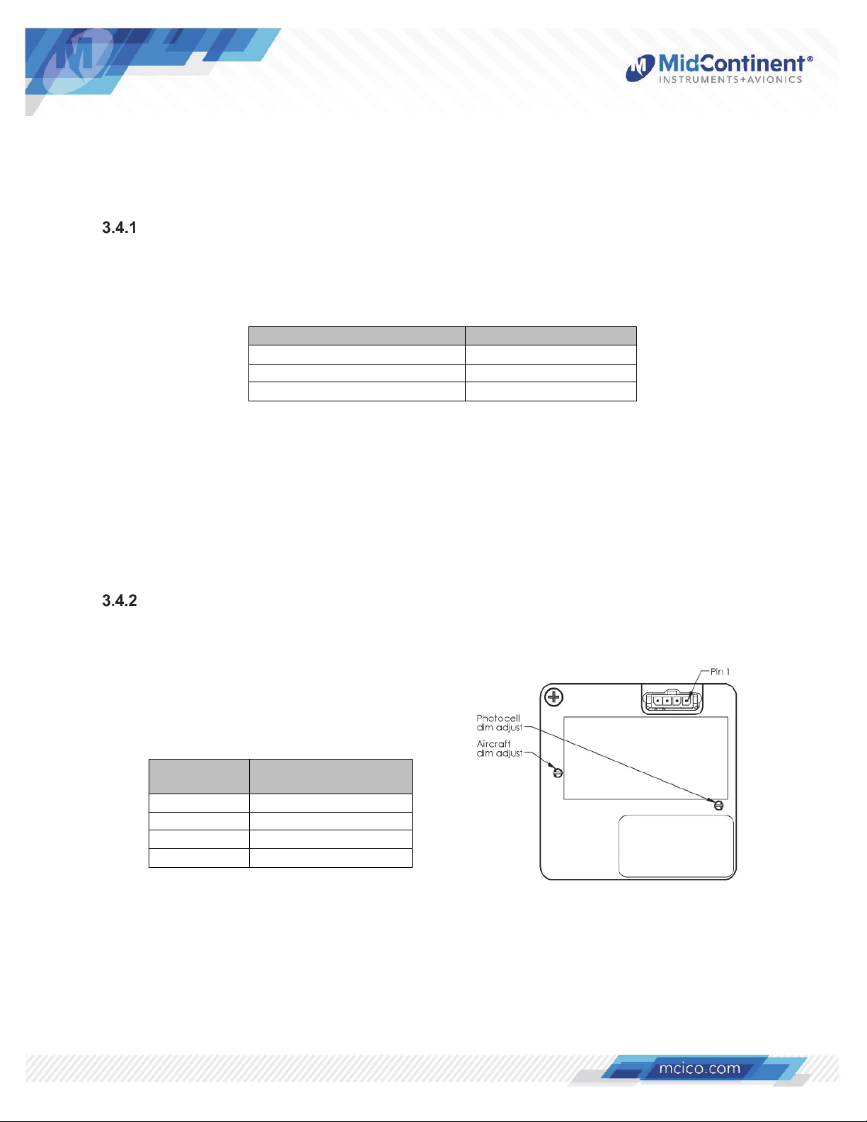
3.4 CABLE HARNESS
Construct the cable harness following the instructions outlined below and per Tables 3.1, 3.2 (Type
1 units) and 3.3 (Type 2 units). Refer to Section 2: Pre-Installation Considerations for routing
precautions.
Wire Gauge Selection
Use of PTFE, ETFE, TFE, Teflon or Tefzel insulated wire is recommended for aircraft use.
The wire harness should utilize 20-24 AWG stranded wire. Refer to Table 3.1 below for
suggested minimum wire size.
Wire Gauge Wire Length
20 AWG stranded wire >35 ft.
22 AWG stranded wire >14 ft.
24 AWG stranded wire <14 ft.
Table 3.1
Wire Gauge and Length
Note: For Type 1 units (-2) pins should be crimped using Molex Hand Crimp Tool 638190000 (preferred), 63811-2800 (obsolete) or 11-01-0200 (obsolete). See the Molex Hand
Crimp Tool User Manual for crimp procedures. For Type 2 units (-0,-3,-4,-5) pins should be
crimped using Positronic Hand Crimp Tool 9507-0-0-0 (preferred), Daniels AFM8 (optional)
or Mil P/N M22520/2-01 (optional).
Pin Assignment Information
See Table 3.2 for pinout definition and Figure 3.1 for pin locations on Type 1 units. Refer to
Table 3.3 for pinout definition and Figure 3.2 for pin locations on Type 2 units.
Pin
Number
1 Aircraft Power
2 Ground
3 Aircraft Lighting Bus
4 Flight Timer Input
Table 3.2 Figure 3.1
Power Input Connector Pinout (Type 1) CH93 Rear View (Type 1)
Signal
Manual Number 9018205 Revision G, May 20, 2021 11
Page 13
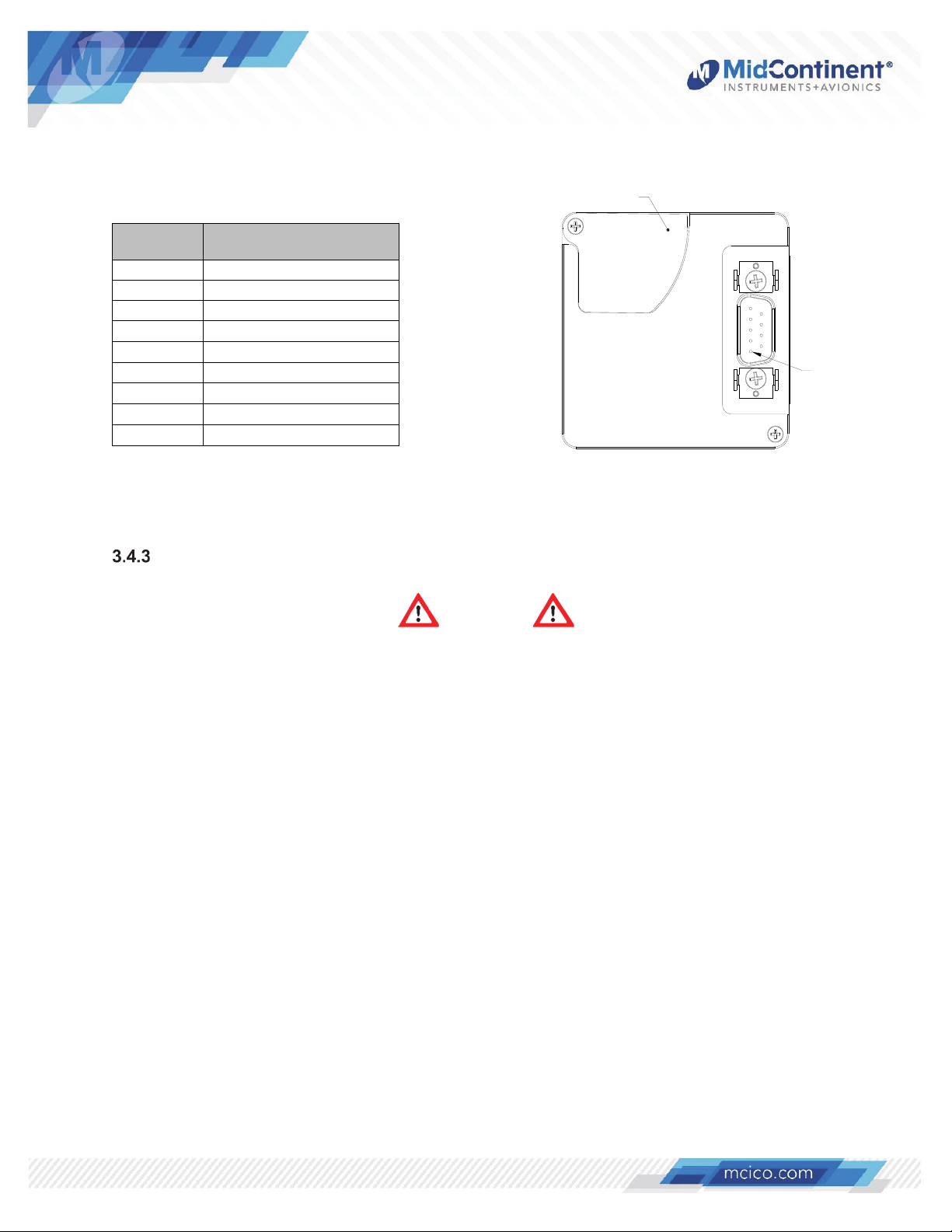
W
Replaceable
Coin Cell (BR2032) Cover
Pin
Number
1 Ground
2
3 Flight Timer Input
4 RTD Temp A
5 Alarm Out
6 Current Temp Return
7 Current Temp Power
8 Aircraft Lighting Bus (DC)
9 RTD Temp B
Power Input Connector Pinout (Type 2) CH93 Rear View (Type 2)
Power Input (DC)
Table 3.3 Figure 3.2
Signal
Pin 1
Harness Verification
ARNING
Failure to install aircraft power and ground wires in the proper mating connector locations
could damage the unit.
Once the cable harness is prepared, prior to connecting the CH93, activate the aircraft power
bus and use a multimeter to verify that aircraft power and ground are supplied with
appropriate voltage on the proper pins within the mating harness.
The CH93 must not be installed with input terminals reversed as this could damage the unit.
Verify the correct polarity of any harness or equipment prior to connecting to the CH93.
Manual Number 9018205 Revision G, May 20, 2021 12
Page 14
W
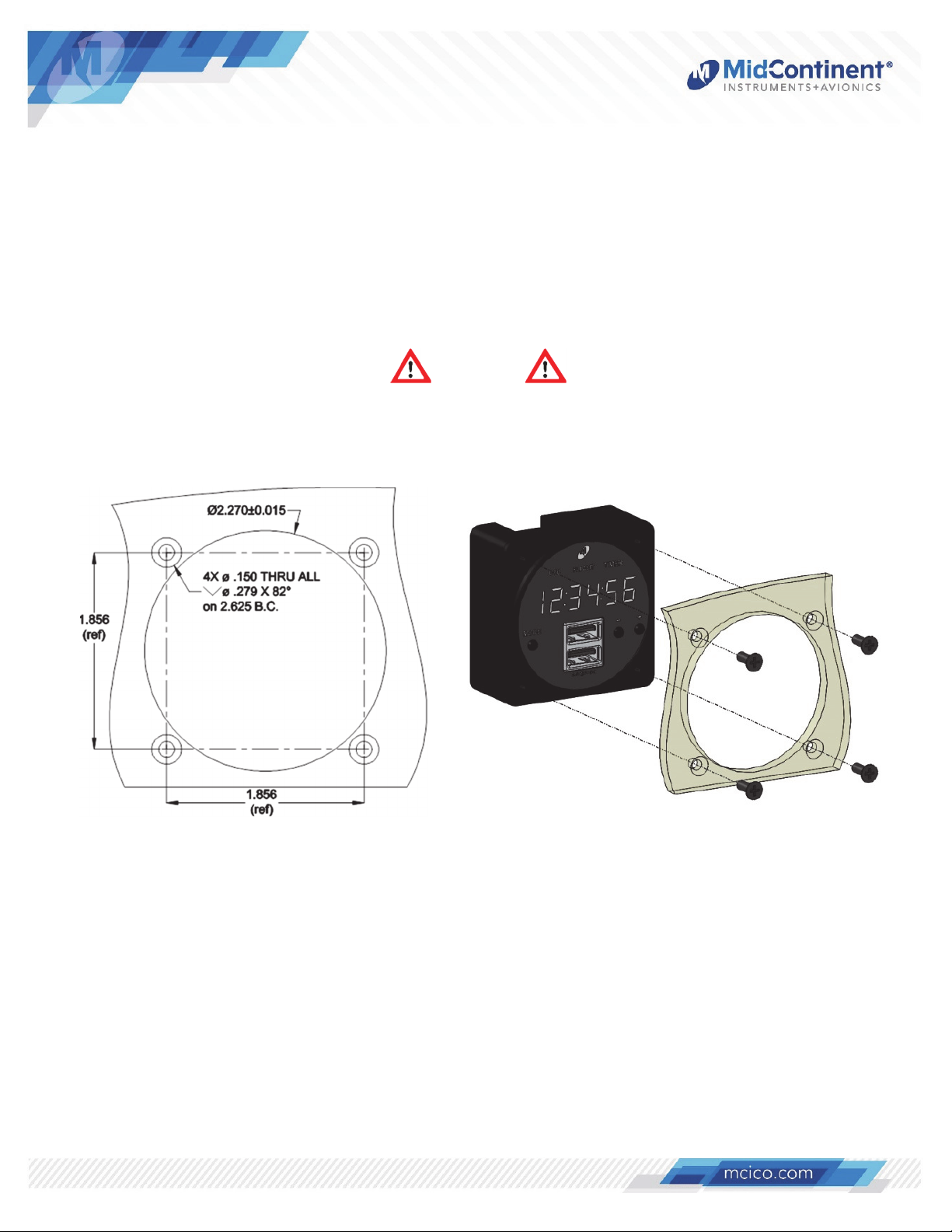
3.5 INSTALLATION
The CH93 is rear mounted using a standard 2 ¼” panel cutout. Prepare the panel cutout as shown
in Figure 3.2 below. For Type 1 units, the display dimming should be adjusted according to Section
4.4 prior to installing the unit. Mount the CH93 with #6-32 flat head screws (provided with
installation kit).
NOTE: The maximum screw length used to mount the unit is 9/32” (0.280”) + panel thickness on
Type 1 units. Type 2 units can accommodate a screw length up to 1” in length.
ARNING
Using screws longer than the recommended maximum length may damage the CH93 unit!
Figure 3.2
Rear Panel Mount Installation
Manual Number 9018205 Revision G, May 20, 2021 13
Page 15
SECTION 4 OPERATION
4.1 UNIT ARCHITECTURE
The CH93 is comprised of two functional building blocks, a USB charger and digital clock. The DC
input voltage is regulated over its specified range using a DC-DC converter to power the USB
charger and all clock functions. A charging port controller manages power output for the USB
charging ports. An internal battery maintains clock functions (local time, universal time, flight timer)
when input power is removed for up to ten years. Type 1 units require factory serviced to be
replaced and Type 2 units have a field-replaceable battery. Refer to Section 5.1 for details.
The user interface is comprised of the display, three control buttons, and the mode annunciation.
The display has six, seven-segment, white LED digits that are 0.360” tall and 0.138” wide. The
three user interface buttons (MODE, – and +) are used to switch between modes of operation, set
clock time, and manage timer functions for the CH93. Backlit annunciations on the front bezel
indicate the current mode of operation with each mode visible only when active. When aircraft
power is removed, the display clock and all annunciations will be turned off.
4.2 CLOCK AND USB PROTECTIVE FEATURES
The following features are included in the design of the CH93 and protect both the unit and any
devices being charged from damage in the event of the fault conditions listed below.
Short Circuit Protection
The CH93 is capable of surviving a short circuit event without permanent damage. The unit
enters an over-current condition so that the average current is significantly reduced and the
device is protected. Removal of the short allows the unit to return to normal operation.
Over-Current Protection
The CH93 monitors current draw individually on each USB port. During an over-current
condition the voltage is reduced. If the voltage falls below 3.8 VDC the output is turned off for
a period of 12 seconds. The output is then checked for continued over-current conditions
every 16 milliseconds. This condition is referred to as a hiccup mode. The device stays in this
mode until the over-current condition is removed, then returns to normal operation.
Low Input Voltage Shutdown
If the input voltage applied to the CH93 drops below the specified minimum, the unit will shut
down until the applied voltage returns to a level within the operating range.
Over-Temperature
If the temperature of the CH93 exceeds designed thresholds due to a fault or excessive load,
the unit communicates with the USB portable device to reduce the charge current output to a
1.0 amp limit. This allows the charger to continue charging while the unit returns to a
temperature within designed limits. When temperature returns to an acceptable level the unit
automatically returns to normal operation.
Manual Number 9018205 Revision G, May 20, 2021 14
Page 16

4.3 USB OPERATION
For units with USB Charging Ports, there are single and dual Type A versions available as well as
the CH93MAX dual Type A/Type C version.
The Type A USB Charging Ports convert the specified DC input voltage range to a 5 VDC output.
Type C USB-PD (Power Delivery) Charging Ports convert the specified DC input voltage range
specified to either 5, 9, 15, or 20 VDC. Both types employ intelligent control and use voltage
signals to negotiate the maximum power (voltage and current) that each individual Personal
Electronic Device (PED) allows. This provides for the fastest charging speeds possible for all
devices including phones, tablets, and laptops. The output voltage and power is applied to the
USB-A ports in per the USB Battery Charging 1.2 Compliance Plan and the USB-C/PD ports in
accordance with USB 3.1 and the USB Power Delivery standards, versions 2.0 and 3.0.
To ensure enhanced cybersecurity protocols, no data is transferred from the unit to the attached
device or from the device to the unit or aircraft systems. Only power and power negotiation signals
are exchanged between the CH93 and the device(s) being charged.
4.4 DIMMING FUNCTIONS
The brightness control on the CH93 can use fully automatic control or a combination of external
and automatic control. For fully automatic control, the internal photocell is used to adjust the
brightness from minimum to maximum brightness by sensing and responding to the current
ambient light conditions. For external control using a dimming bus adjustment, the brightness can
be manually controlled by supplying a lighting input voltage. The lighting input voltage will be
compared to the power input and will control the lighting when it is between 20-100% of the power
input. A voltage equal to the aircraft bus voltage (100%) corresponds to maximum brightness. If
the lighting voltage is less than 20% of the power input voltage (or off), dimming will be
automatically controlled by the ambient light sensed by the photocell built into the unit.
Display Dimming Adjustment (Type 1 units)
To adjust the brightness range of the clock on Type 1 units for optimal daytime and night-time
viewing, as well as balance amongst other panel instruments, use the two trimming
potentiometers (trim pot) adjustments on the rear of the unit as shown in Figure 3.1. Set the
input voltage/lighting bus to maximum and turn the “Aircraft Dim Adjust” screw to raise or
lower the brightness. Next, turn the input voltage/lighting bus off in completely dark conditions
and turn the “Photocell Dim Adjust” screw to raise or lower the brightness.
CAUTION
NOTE: For Type 1 units, the adjustment screw has a single 360° range of rotation.
Exceeding its limits past the stops will damage the unit. Adjust lightly.
Manual Number 9018205 Revision G, May 20, 2021 15
Page 17
Display Dimming Adjustment (Type 2 units)
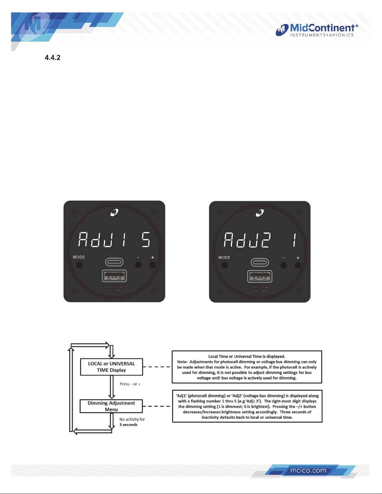
For Type 2 units, the brightness range of the clock can be adjusted before or after installation
using the control buttons on the front of the unit. With the unit in either LOCAL or UTC mode,
simply pressing the – or + buttons will adjust the brightness setting. The CH93 will
automatically detect and adjust the brightness control method that is currently active. If the
automatic photocell is active, ADJ1 is displayed. It is recommended to set the photocell
adjustment level in a dark or night-time cockpit environment. If the unit is receiving a dimming
input voltage, ADJ2 is displayed. If used, both should be set to the appropriate preference.
Once set, the photocell and lighting bus adjustments will be saved in the clock configuration.
If the brightness of the clock needs to be increased or decreased during flight, this can be
performed in either LOCAL or UTC mode using the same procedure previously described.
Refer to Figure 4.3 for detailed instructions on adjusting dimming for Type 2 units (for both
photocell and lighting bus display dimming modes).
Figure 4.1 Figure 4.2
Photocell Dimming Adjustment Bus Voltage Dimming Adjustment
(-5 unit shown) (-5 unit shown)
Figure 4.3
Dimming Adjustment (Type 2 units only)
Manual Number 9018205 Revision G, May 20, 2021 16
Page 18
4.5 OPERATIONAL MODES
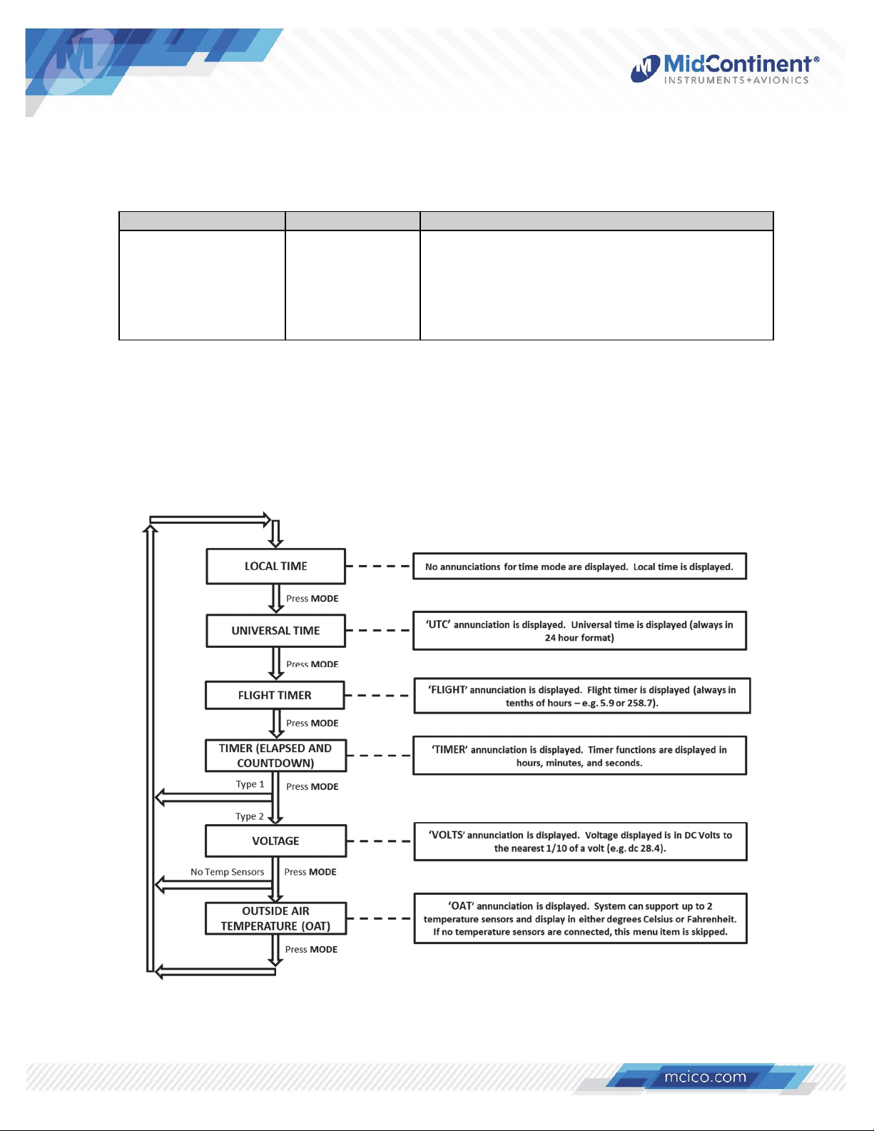
The CH93 has six modes of operation representing up to nine separate functions. Each mode,
when applicable, is indicated by a backlit annunciation on the display. See table 4.1 for details.
Mode Annunciation Functions
Local Time
Universal Time
Flight Timer
Timer
Voltage*
Temperature*^
(none)
UTC
FLIGHT
TIMER
VOLTS
OAT
Modes and Functions
Display and set local time
Display and set UTC time
Resettable and non-resettable flight timers
Elapsed (count up) and count-down timers
Displays bus voltage
Displays OAT and/or cockpit/cabin temperature
* Only available on Type 2 units
^ Requires temperature probe sensors
Table 4.1
Pressing the MODE button scrolls through the six different operational modes in a counterclockwise direction on the display. Figure 4.4 depicts the overall flow of the unit modes of
operation. Details for each mode are provided in the subsequent sections.
Figure 4.4
Modes of Operation
Manual Number 9018205 Revision G, May 20, 2021 17
Page 19
Local Time Mode
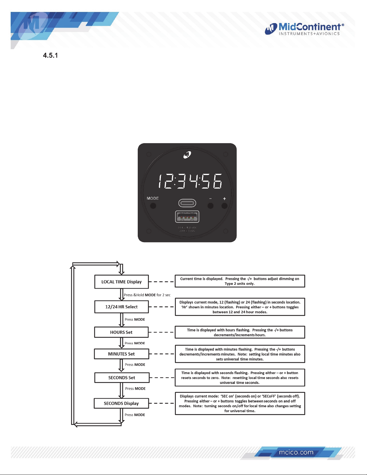
When power is applied to the CH93, the system defaults to Local Time mode (in this mode,
there is no mode indication/annunciation; refer to Figure 4.5). Pressing and holding the
MODE button will enter the configuration menu. The local time can be configured to display
preferences for 12- or 24-hour format and to either display or hide seconds (displaying or
hiding seconds setting applies to both local and UTC time). Setting hours in local time is
independent of UTC time. For setting the minutes, Type 1 units apply the setting to both local
and UTC time concurrently and are linked. For Type 2 units, the minutes in local time are
independent of the UTC time minutes. For both unit types, the seconds are synchronized
and linked between the two time modes. Refer to Figure 4.6 for detailed instructions.
Figure 4.5
Local Time Clock Mode (-5 unit shown)
Figure 4.6
Setting Local Time
Manual Number 9018205 Revision G, May 20, 2021 18
Page 20
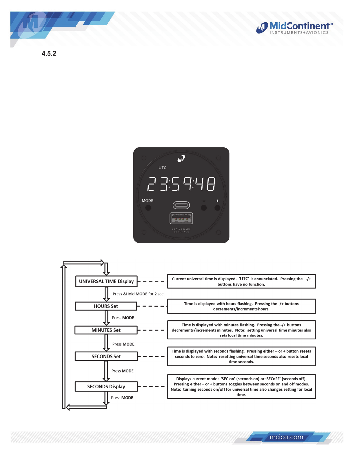
Universal Time Mode
When in Local Time mode, pressing the Mode button once changes the unit to Universal
Time mode and the UTC annunciation will be backlit (refer to Figure 4.7). Pressing and
holding the MODE button will enter the configuration menu. UTC time is always displayed in
24-hour format and seconds can be configured to be displayed or hidden (displaying or
hiding seconds setting applies to both local and UTC time). Setting hours in UTC time is
independent of local time. For setting the minutes, Type 1 units apply the setting to both local
and UTC time concurrently and are linked. For Type 2 units, the minutes can be set for UTC
time in 15-minute increments, independently of local time, to allow for time zones with offsets
that are less than 1-hour increments. For both unit types, the seconds are synchronized and
linked between the two time modes. Refer to Figure 4.8 for detailed instructions.
Figure 4.7
Universal Time Clock Mode (-5 unit shown)
Figure 4.8
Setting Universal Time
Manual Number 9018205 Revision G, May 20, 2021 19
Page 21
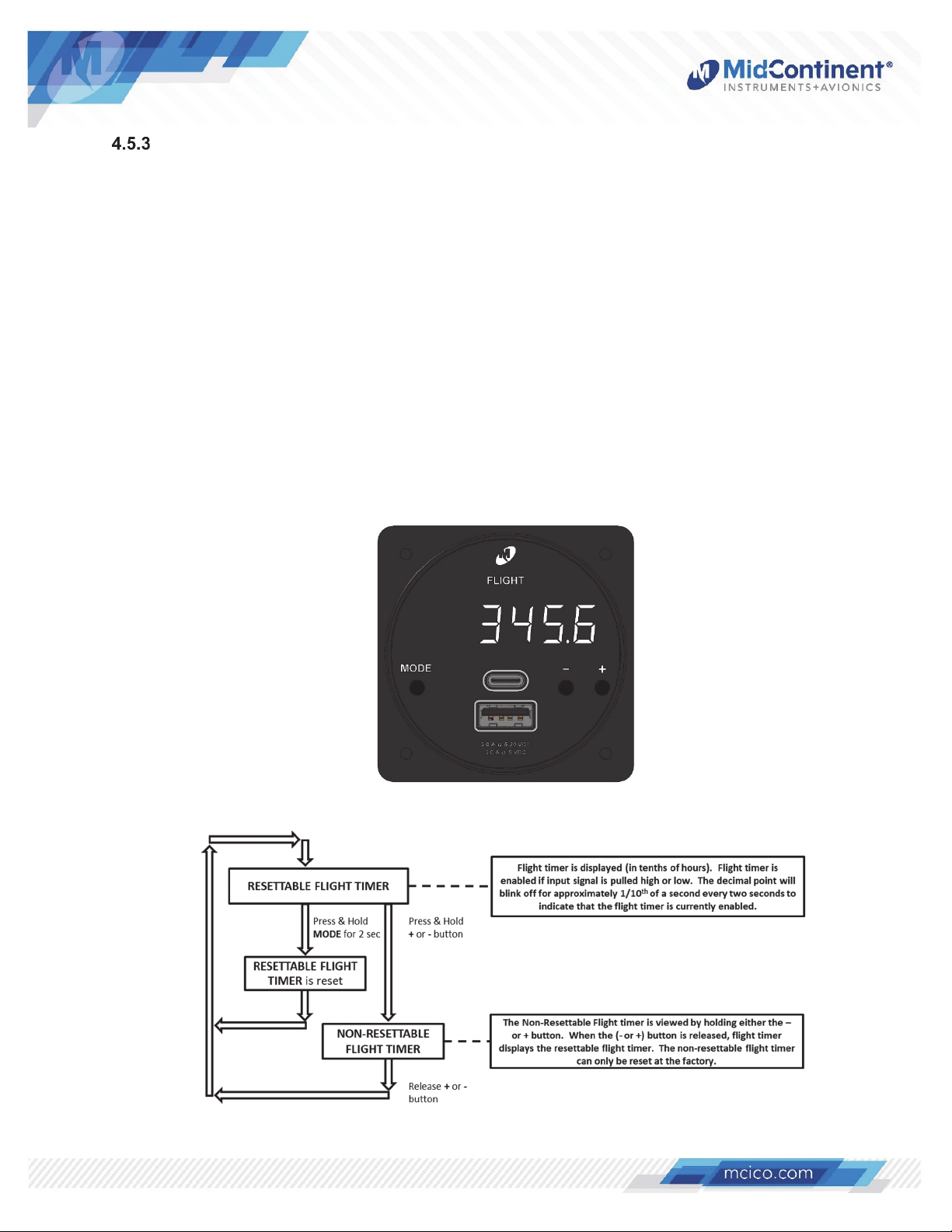
Flight Timer Mode
When in UTC mode, pressing the Mode button once changes the unit to Flight Timer mode
and the FLIGHT annunciation will be backlit (refer to Figure 4.9). To activate the flight timer, a
ground or aircraft power signal must be supplied to the Flight Timer Enable Pin (see Tables
3.3 and 3.4). This can be provided from an event-based relay (such as engine start or weighton-wheels) or it can be connected via jumper to the power or ground pins of the unit to
activate on unit power. The decimal point will blink briefly every 2 seconds to indicate that the
flight timer is active. Flight time is displayed in hours and tenths of hours up to 99999.9 hours.
The flight timer maintains the accumulated time (but does not run) when power is off.
Two flight timers are available on the CH93. The default flight timer is a resettable timer.
Pressing and holding the MODE button for two seconds will reset the timer. If the Flight Timer
Enable signal is active, the flight timer will reset to zero and resume counting. Pressing and
holding the – or + button will display the non-resettable flight timer for keeping total
cumulative flight time. Releasing the – or + button will return the display to the resettable
flight timer. Note: the non-resettable timer value can be set or reset at the factory only. Refer
to Figure 4.10 for detailed instructions.
Figure 4.9
Flight Timer Mode (-5 unit shown)
Figure 4.10
Flight Timer Operation
Manual Number 9018205 Revision G, May 20, 2021 20
Page 22
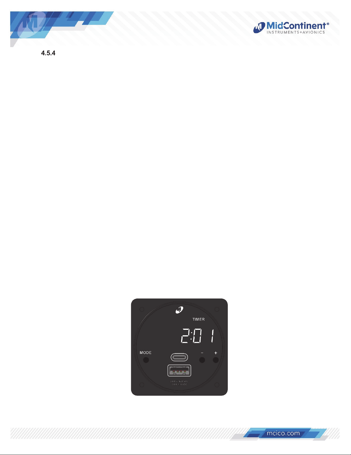
Timer Mode
When in Flight Timer mode, pressing the Mode button once changes the unit to Timer mode
and the TIMER annunciation will be backlit (refer to Figure 4.11). The timer function can be
operated as either an elapsed timer (stopwatch) or countdown timer, where a specific
countdown time can be set. Upon power up, the CH93 remembers countdown timer setting
and will default to the last displayed mode (elapsed or countdown). Once in Timer mode,
pressing and holding the Mode button will allow the selection of elapsed or countdown mode.
Note: When either timer is active, the user can change modes (e.g. to Local Time) and the
timer will still remain active. The timer stops and resets if power is cycled or if the timer mode
(elapsed vs. countdown) is changed.
4.5.4.1 Elapsed Timer
When entering Timer mode, the unit is in Elapsed Timer mode if the display shows
00:00:00 or the unit is counting up (and not blinking). The elapsed timer counts up to a
maximum of 99 hours, 59 minutes, 59 seconds and then starts again at zero.
Pressing the + button starts and stops the timer. Pressing the – button resets the timer
only if the timer is stopped. Refer to Figure 4.12 for detailed instructions.
4.5.4.2 Countdown Timer
Once the countdown mode is selected, the unit immediately allows the setting of the
specific countdown time. The countdown timer can be set to a maximum of 99 hours, 59
minutes, 59 seconds. Pressing the + button will start and stop the timer. When the
countdown timer reaches 00:00:00, it will enable the external alarm (ground output on
pin 5; Type 2 units only) and it will begin counting up and will flash every second to
indicate elapsed time since reaching zero. Pressing the – button resets the timer only if
the timer is stopped and it will also reset the external alarm. The countdown timer setting
is maintained when the unit is powered off. Refer to Figure 4.12 for detailed instructions.
Figure 4.11
Timer Mode (-5 unit shown)
Manual Number 9018205 Revision G, May 20, 2021 21
Page 23
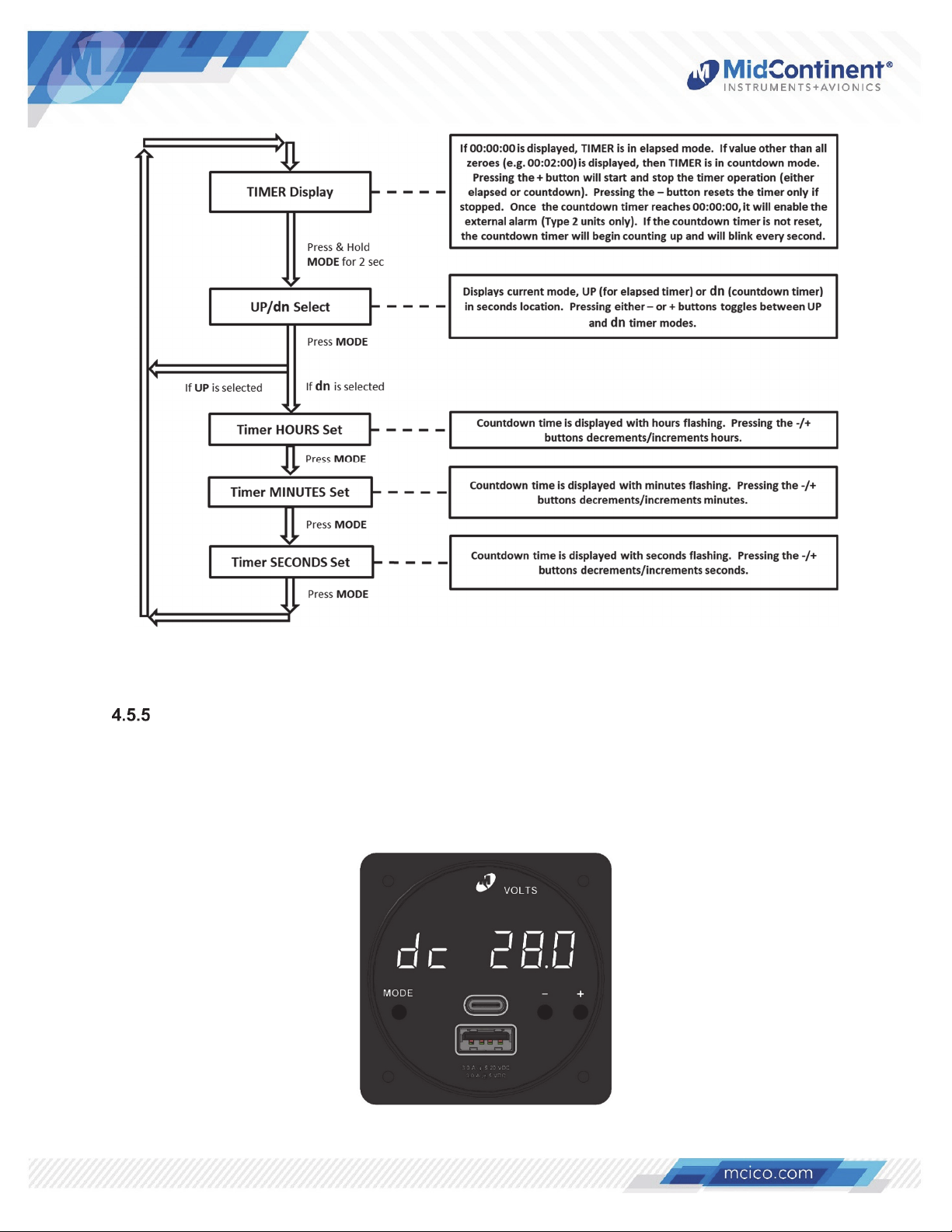
Figure 4.12
Elapsed/Countdown Timer Operation
Voltage
When in Timer mode, pressing the Mode button once changes the unit to Voltage mode and
the VOLTS annunciation will be backlit (refer to Figure 4.13). Voltage mode is only available
in CH93 Type 2 units. When in Voltage mode, the bus voltage (Volts DC (Direct Current)) is
th
displayed to the nearest 1/10
of a volt and preceded by the “dc” label.
Refer to Figure 4.13 below.
Figure 4.13
Voltage Mode (-5 unit shown)
Manual Number 9018205 Revision G, May 20, 2021 22
Page 24
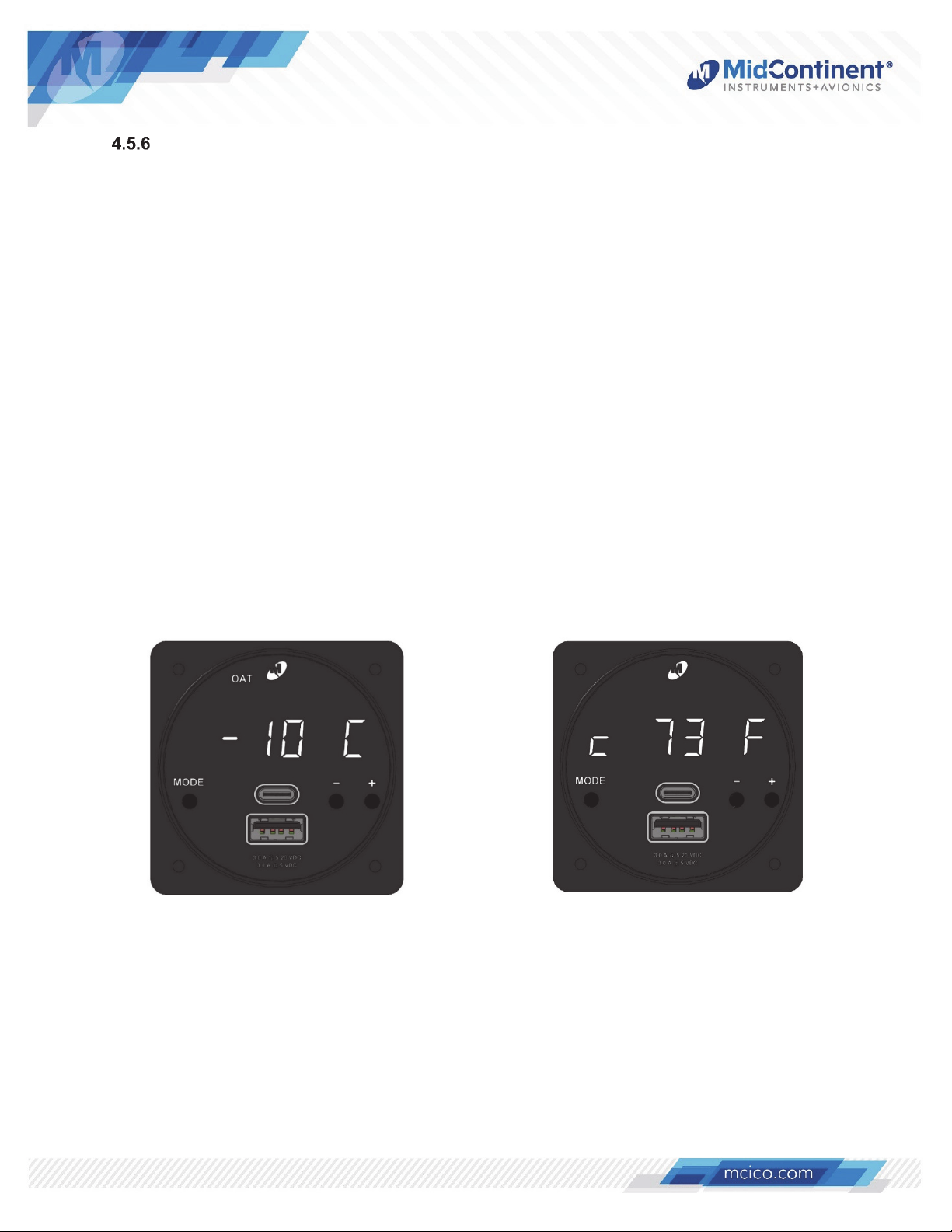
Temperature Mode
When in Voltage mode, pressing the Mode button once changes the unit to Temperature
mode and the OAT (Outside Air Temperature) annunciation will be backlit (refer to Figure
4.17). Temperature mode is only available in CH93 Type 2 units and requires the use of one
or two temperature probes (sold separately; refer to Section 3.3 and 4.6). When a
temperature probe is detected, the temperature is displayed to the nearest degree (°) in
either Celsius (C) or Fahrenheit (F). If there are no temperature probes installed or detected,
Temperature mode will be unavailable and the unit will transition from Voltage mode to Local
mode when pressing the Mode button.
The CH93 Type 2 unit is designed to support one or two temperature inputs. One input is
designed to measure and indicate Outside Air Temperature (OAT) and the other to measure
and indicate inside (cockpit or cabin) air temperature. Either or both are allowable. If a
temperature input is configured as OAT, the OAT annunciation will be backlit. If configured as
cockpit/cabin temperature, no mode annunciation will be shown and the first digit of the
display will indicate the letter “c” (Refer to Figure 4.18) When both are installed, pressing the
– or + button will switch between OAT and cockpit/cabin temperature. The last viewed
temperature will remain as the default view when cycling through the modes, until changed
again.
To change the units of the temperature display (C or F), press and hold the MODE button.
Refer to Figure 4.19 for detailed instructions
Figure 4.17 Figure 4.18
Temperature Mode Temperature Mode
Outside Air Temperature (-5 unit shown) Cockpit/Cabin Temperature (-5 unit shown)
Manual Number 9018205 Revision G, May 20, 2021 23
Page 25
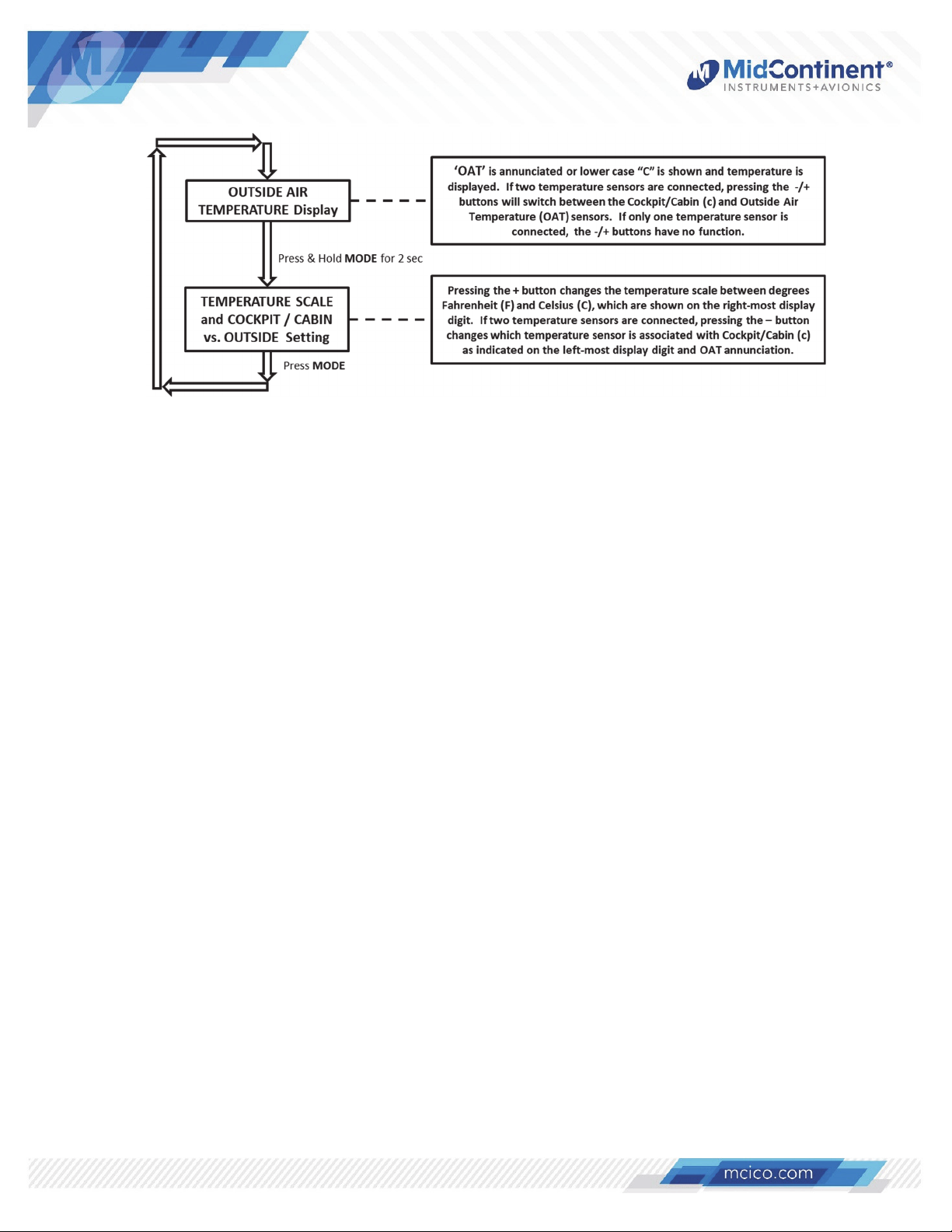
Figure 4.19
Temperature Mode Operation
4.5.6.1 Temperature Probe Configuration
The CH93 supports two different types of temperature probes; RTD and current sense
devices. If only one of the above probes is connected to the CH93, the temperature
display will initially appear like Figure 4.17. If two probes are connected (must be one of
each type), the unit can be configured to identify one probe as Outside Air Temperature
and the other as interior (cockpit/cabin) temperature.
To configure the first temperature probe, follow instructions in Figure 4.20. If two probes
are connected, configure the second temperature probe similarly per instructions in
Figure 4.21.
Manual Number 9018205 Revision G, May 20, 2021 24
Page 26
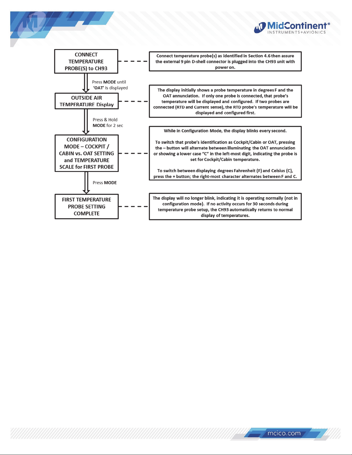
Figure 4.20
Temperature Sensor Configuration
(First Temperature Probe)
Manual Number 9018205 Revision G, May 20, 2021 25
Page 27
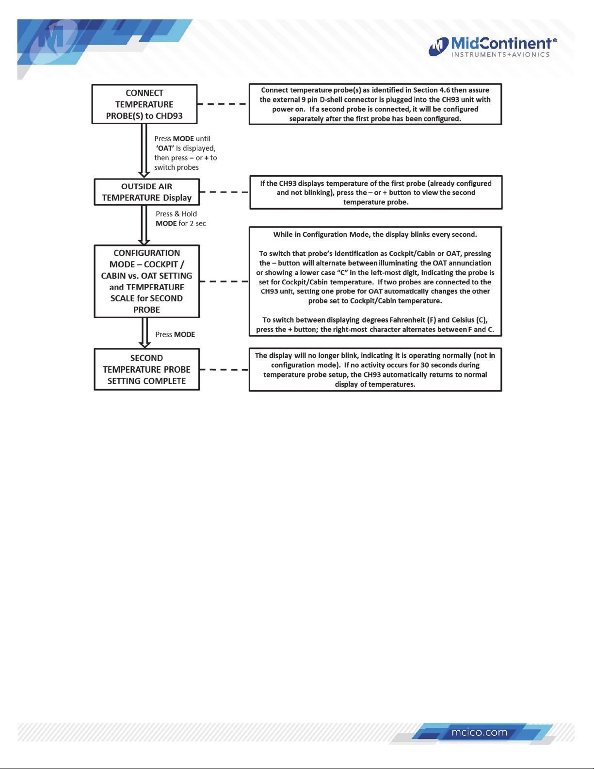
Figure 4.21
Temperature Sensor Configuration
(Second Temperature Probe)
Manual Number 9018205 Revision G, May 20, 2021 26
Page 28
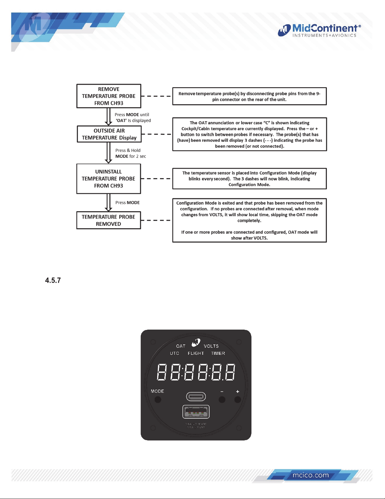
4.5.6.2 Uninstalling Temperature Probes
To uninstall (un-configure) a temperature probe(s), follow instructions per Figure 4.22.
Figure 4.22
Temperature Sensor Configuration
(Uninstalling Temperature Probes)
Display Test Mode
To test the CH93 display, press and hold both +/- buttons for 2 seconds. After 2 seconds all
display segments and annunciators will be activated until the + and - buttons are released.
Refer to Figure 4.23.
Figure 4.23
Display Test Mode (-5 unit shown)
Manual Number 9018205 Revision G, May 20, 2021 27
Page 29
4.6 TEMPERATURE PROBE INSTALLATION
The CH93 (Type 2) supports two types of temperature probes: an RTD (Resistance Temperature
Detector; 500 Ω) and a Temperature Transducer (current sense device; AD590). This section
describes compatible probes available for installation for the CH93 Type 2 unit. Either may be used
(if only one) or one of each type.
RTD Probes
To install either of the RTD-style probes for OAT or cockpit/cabin temperature, connect to
pins 4 and 9 (no polarity required) of the mating connector of the CH93 per the instructions
below.
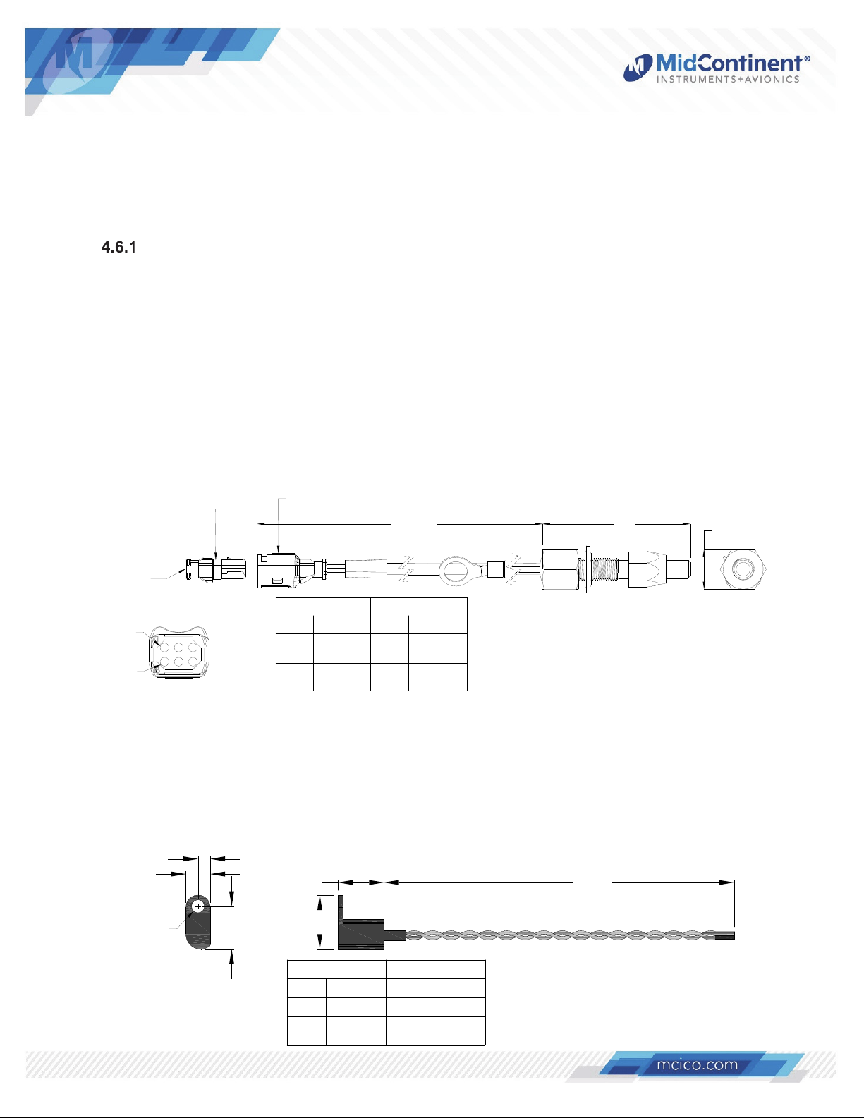
4.6.1.1 OAT RTD Probe
The MCIA p/n B-10-1 is a 13-inch long Outside Air Temperature RTD Probe furnished
with a 6 pin connector and mating socket connector kit. The probe mounts in a 5/16”
diameter hole through the aircraft skin. Use 22 gauge wire to create a harness that
connects the probe’s mating connector to the CH93 mating 9-pin d-sub connector
Refer below to Figure 4.14 for pinout connection to the CH93 unit. Refer to Figure 4.24.
TE DEUTSCH 369
6 Socket Connector
22 Ga Wire
Customer
Supplied
Pin 1
Pin 6
TE DEUTSCH 369
6 Pin Connector
13.0 ± 0.3 2.07
B-10-1 Probe CH93
Description
Pin
2
3
Signal
High
Signal Low
Pin
4RTD Out
9
4.6.1.2 Interior RTD Temperature Probe
The MCIA p/n B-11-1 is a 120-inch long (10 foot) Cockpit/Cabin Temperature RTD Probe
that mounts by either a #8 (or smaller) screw or cable tie to any interior location. To
connect the B-11-1 probe to the CH93 unit, remove excess cable length from the probe,
strip ends, and connect to the CH93 mating 9-pin d-sub connector. Refer to Figure 4.25.
0.16
0.33
0.62 120±2.0
Description
RTD
Return
Figure 4.24
B-10-1 Temperature Probe
0.563 (9/16)
HEX
Ø0.17
Manual Number 9018205 Revision G, May 20, 2021 28
0.58
0.73
B-11-1 Probe CH93
Description
Wire
Black
RTD Pin 1 4 RTD Out
Black
RTD Pin 2
Pin
9
Description
RTD
Return
Figure 4.25
B-11-1 Temperature Probe
Page 30
Transducer Probes
To install any of the Transducer-style probes for OAT or interior temperature, connect pins 6
and 7 (polarity required) to the mating connector of the CH93 per the instructions below.
4.6.2.1 OAT Transducer Probes
The CH93 is compatible with the following OAT Transducer Probes:
(not available through MCIA)
Davtron p/n C307PS
Davtron p/n 655
To install these probes, connect the power line to pin 7 and the return line to pin 6 of the
CH93 mating 9-pin d-sub connector.
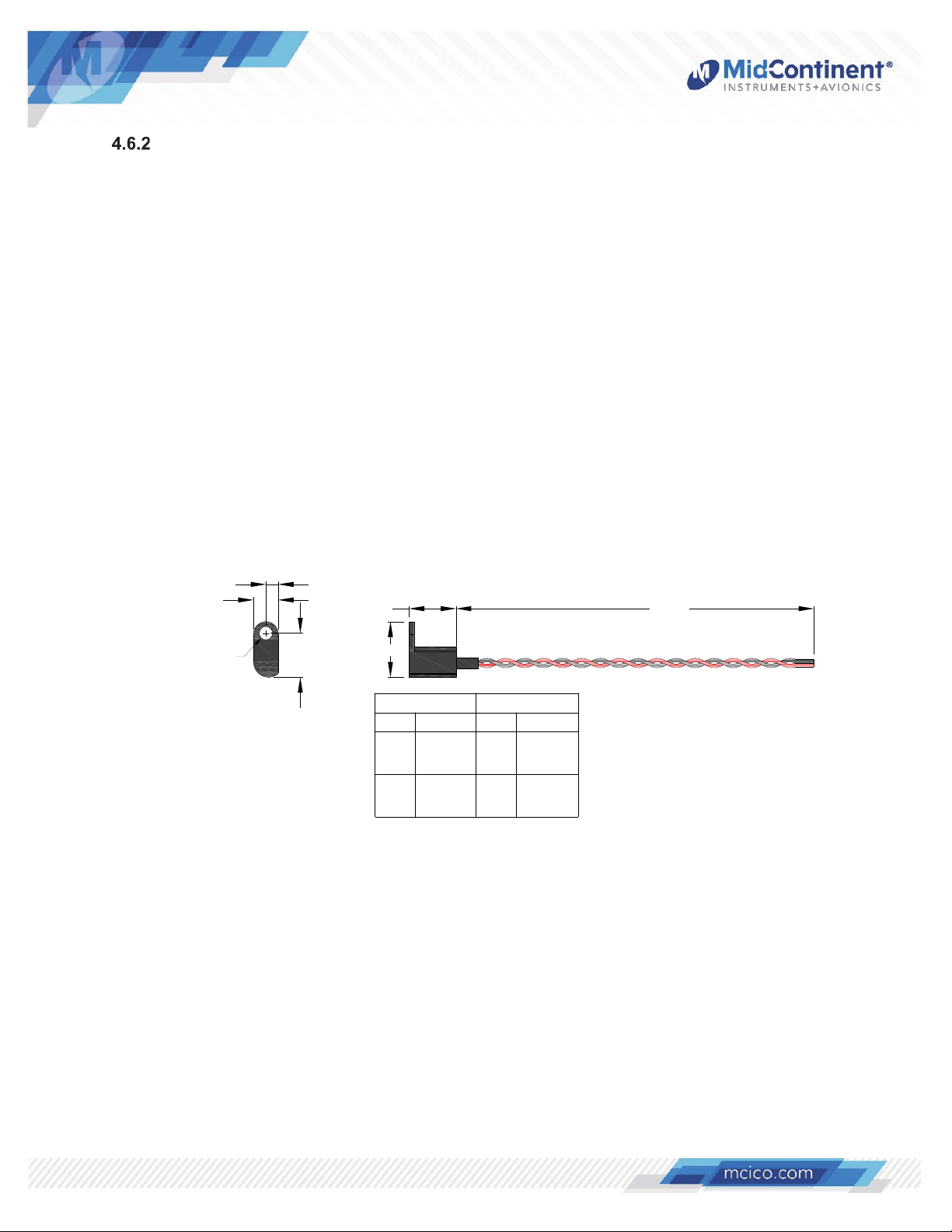
4.6.2.2 Interior Transducer Probe
The MCIA p/n B-11-2 is a 120-inch long (10 foot) Cockpit/Cabin Interior Temperature
Current Sense Transducer Probe that mounts by either a #8 (or smaller) screw or cable
tie to any interior location. To connect the B-11-2 probe to the CH93 unit, remove excess
cable length from the probe, strip ends, and connect to the CH93 mating 9-pin d-sub
connector as follows: Black wire to pin 6 (Return) and Red wire to pin 7 (Power).
0.16
0.33
0.62 120±2.0
Ø0.17
0.58
0.73
B-11-2 Probe
Description
Wire
Black Return 6
Red Power 7
Pin
CH93
Description
Temp
Sensor
Return
Temp
Sensor
Power
Figure 4.26
B-11-2 Temperature Probe
Manual Number 9018205 Revision G, May 20, 2021 29
Page 31
SECTION 5 CONFORMANCE
5.1 INSTRUCTIONS FOR CONTINUED AIRWORTHINESS
No periodic scheduled maintenance or calibration is necessary for continued airworthiness of the
CH93 Digital Clock / Dual USB Charging Port.
If the unit fails to perform to specifications, the unit must be removed and serviced by MidContinent Instruments and Avionics or their authorized designee.
If the unit fails to maintain local or UTC time upon power-up, the internal battery must be replaced
per the instructions below.
Type 1 units: Remove unit from service and return to Mid-Continent Instruments and Avionics for
battery replacement.
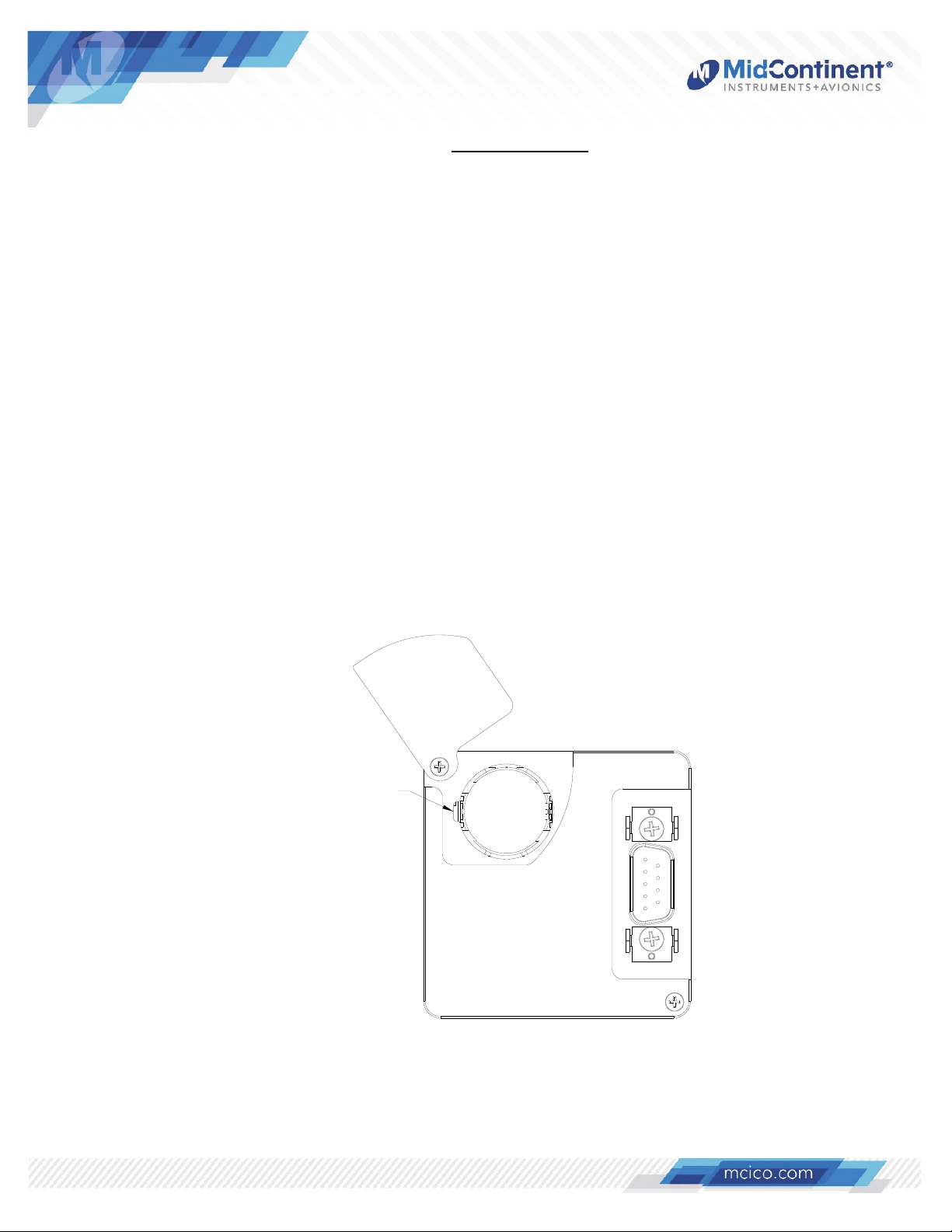
Type 2 units: Remove unit from the panel and loosen the screw retaining the battery cover door on
the rear of the unit. Rotate the battery door counter-clockwise and carefully remove the battery with
a non-conductive flat blade object on the side with the battery holder notch. Replace with a new
battery of the same type (BR 2032; compliant with UL 1642).
Verify time remains set after a power cycle and return to service.
Refer to Figure 5.1 below for battery replacement.
Remove battery
from this side
Figure 5.1
Battery (coin cell) Removal
(Type 2 units only)
Manual Number 9018205 Revision G, May 20, 2021 30
Page 32
gory
gory
gory
gory
gory B(XX)
A
y
gory
gory
gory
y
gory
gory
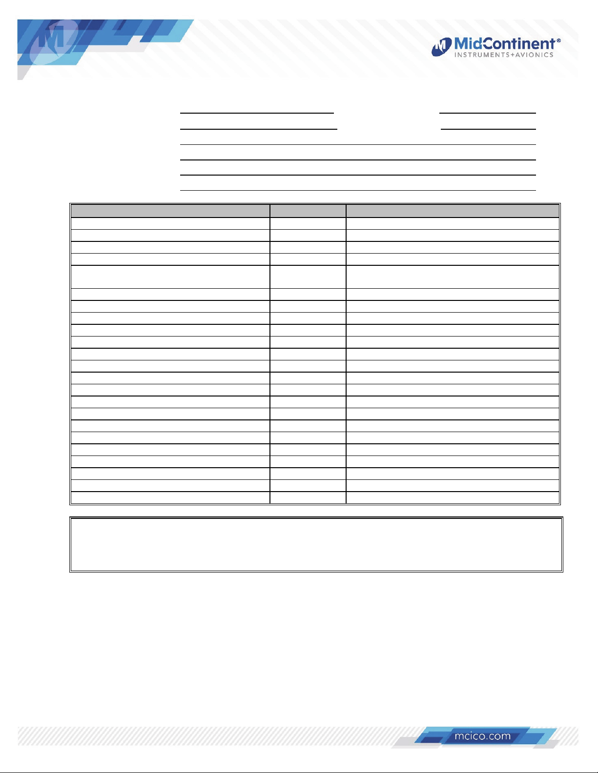
5.2 ENVIRONMENTAL QUALIFICATION STATEMENT
MODEL NUMBER: CH93 Series PART NUMBER: 6420093-( )
DESCRIPTION: Digital Clock/USB Charging Port CERTIFICATION: FAA TSO-C71
MANUFACTURER: Mid-Continent Instrument Co., Inc.
ADDRESS: 9400 E. 34th St. North, Wichita, KS 67226, USA.
SPECIFICATION: Test Specification (TS) 509 Test Data Sheet (TDS) 509 and 093
STANDARD: RTCA DO-160, Rev G, dated 12/08/2010
CONDITIONS SECTION DESCRIPTION OF TEST
Temperature and Altitude 4 Category F1
Temperature Variation 5 Category S2
Humidity 6Cate
Operational Shock and Crash Safety 7 Cate
Vibration 8 Fixed Wing: Category R, Curves C & C1
Rotorcraft: Cate
Explosion 9 Category X
Waterproofness 10 Category X
Fluids 11 Category X
Sand and Dust 12 Category X
Fungus 13 Category X
Salt Fog 14Cate
Magnetic Effect 15 Category Y
Power Input 16Cate
Voltage Spike 17 Category B
udio Frequency Conducted Susceptibilit
18 Category R
Induced Signal Susceptibility 19 Cate
Radio Frequency Susceptibility 20 Cate
Emission of Radio Freq Energy 21 Cate
Lightning Induced Transient Susceptibilit
22 Category X
Lightning Direct Effects 23 Category X
Icing 24Cate
ESD 25 Category A
Fire, Flammability 26Cate
REMARKS:
Section 4: Category F1 with excursions as declared by the manufacturer: Operating Low Temperature performed
at Short-time Low Temperature set point of -40C.
Section 8: Vibration was performed per Cat R, Curves C & C1 for fixed-wing aircraft and per Cat U, Curve G for
helicopter using the same test article.
B
B
U, Curve G
X
X
X
M
X
X
Manual Number 9018205 Revision G, May 20, 2021 31
 Loading...