

Page 1
INSTALLATION MANUAL AND
OPERATING INSTRUCTIONS
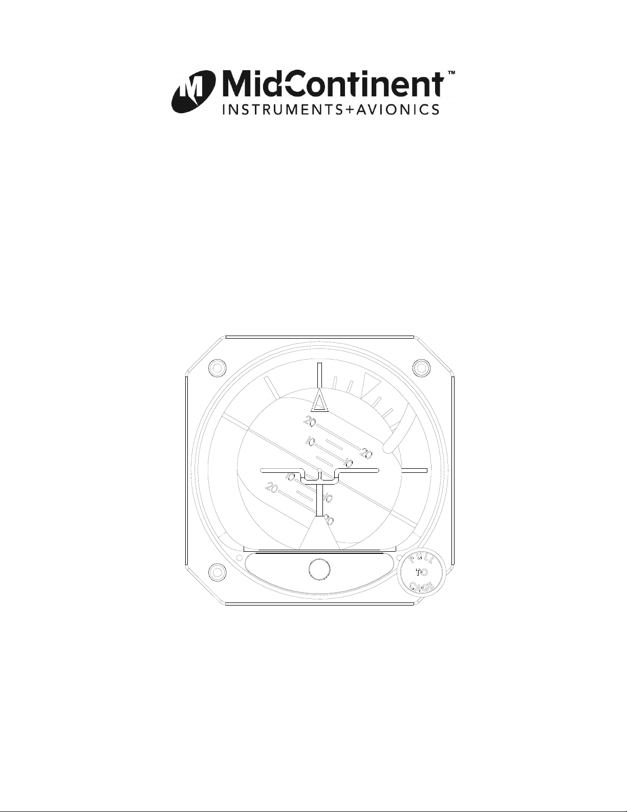
4300-202/-203/-213 Series Electric Attitude Indicator
Mid-Continent Instruments and Avionics Manual Number 9016082
9400 E 34
Phone 316-630-0101 Fax 316-630-0723
th
Street N, Wichita, KS 67226 USA REV B March 27, 2014
Page 2

Mid-Continent Instruments and Avionics, Wichita, KS
FOREWORD
This manual provides information intended for use by persons who, in accordance with current
regulatory requirements, are qualified to install this equipment. If further information is required,
please contact:
Mid-Continent Instruments and Avionics
Attn: Customer Service Dept.
9400 E. 34
Wichita, KS 67226 USA
Phone 316-630-0101 Fax 316-630-0723
We welcome your comments concerning this manual. Although every effort has been made to
keep it free of errors, some may occur. When reporting a specific problem, please describe it
briefly and include the manual part number, the paragraph/figure/table number, and the page
number. Send your comments to:
Mid-Continent Instruments and Avionics
Attn: Technical Publications
9400 E. 34
Wichita, KS 67226 USA
Phone 316-630-0101, Fax 316-630-0723
Copyright 2004
Mid-Continent Instruments and Avionics
th
ST North
th
ST North
REV B March 27, 2014 Manual Number 9016082 Page 2 of 13
Page 3

Mid-Continent Instruments and Avionics, Wichita, KS
Table of Contents
Page
Section 1 General Description 5
1.1 Purpose of Equipment 5
1.2 Physical Description 5
1.3 Functional Description 5
1.4 Gyro Warning Flag 5
1.5 Options and Configurations 5
1.6 Specifications 6
Section 2 Installation 8
2.1 General 8
2.2 Pre-Installation Inspection 8
2.3 Parts 8
2.3.1 Included Parts 8
2.3.2 Installer Supplied Parts 8
2.3.3 Additional Optional Parts 9
2.4 Equipment Location 9
2.5 Installation 9
2.6 Continued Airworthiness 9
Section 3 Operation 12
3.1 General 12
3.2 Starting Procedures 12
3.3 In-Flight Procedures 12
3.4 Dynamic Errors 12
3.5 Equipment Limitations 13
Figure No. List of Illustrations
1.1 Typical Indicator Display Detail 7
2.1 Outline Drawings 10
2.2 Rear-Mount Cutout Dimensions 11
2.3 Front-Mount Cutout Dimensions 11
Table No. List of Tables
1.1 Configuration Table 5
1.2 Physical Characteristics 6
1.3 Performance 6
REV B March 27, 2014 Manual Number 9016082 Page 3 of 13
Page 4
Mid-Continent Instruments and Avionics, Wichita, KS
Revision Detail
ECO
A 10/7/04 Initial Release
6148 B 3/27/14 Added -213 configuration.
Rev. Date Description
REV B March 27, 2014 Manual Number 9016082 Page 4 of 13
Page 5
Mid-Continent Instruments and Avionics, Wichita, KS
Section 1: General Description
1.1 Purpose of Equipment
The Model 4300-202/-203/-213 Electric Attitude Indicator incorporates a moving display that
simulates the earth’s horizon and provides the pilot with a real time visual indication of the
aircraft pitch and roll attitude relative to the indicator symbolic airplane.
The instrument can function as a primary or standby indicator with special configurations
available to match existing systems or electronic flight displays.
1.2 Physical Description
The 4300-202/-203/-213 Electric Attitude Indicator incorporates pitch and roll displays that are
mechanically linked to a spinning mass gyroscope. The horizon bar moves behind the symbolic
airplane. Precession error is corrected by the 4300’s erection system or by pulling the “PULL TO
CAGE” knob. A warning flag drops into view to indicate that the gyro motor is not receiving
sufficient power to operate.
1.3 Functional Description
Model 4300-202/-203/-213 Electric Attitude Indicators employ an efficient electrically driven
internal vertical gyroscope assembly incorporating a special air erection mechanism. This
mechanism simultaneously erects the pitch and roll axes of the gyroscope. Movement of the
aircraft generates a reaction of the display that simulates the visual reference seen by the pilot
when looking outside at the earth’s true horizon line.
The Indicator requires 10 to 32 VDC input voltage.
1.4 Gyro Warning Flag
A power warning circuit monitors the electrical current used to power the gyro motor. When a
loss of input voltage occurs, the gyro warning flag comes into view.
1.5 Configuration
Configuration Table
4300-202 4300-203 4300-213
Panel Tilt Calibration
Input Voltage 10-32 VDC 10-32 VDC 10-32 VDC
Roll Dial Rotating Rotating Rotating
Symbolic Airplane Traditional Traditional Traditional
Lighting Not included Not included Not included
Slip Indicator Not included Included Included
11 11 17
Table 1.1
REV B March 27, 2014 Manual Number 9016082 Page 5 of 13
Page 6
Mid-Continent Instruments and Avionics, Wichita, KS
1.6. Specifications
Physical Characteristics:
Qualification: FAA-TSO-C4c
Environmental Qualification: RTCA DO-160D Environmental Category
A2BAB[(SBM)(RBB1)]XXXXXXZZAZZ[RR]M[A3C3]XXA
Weight: 2.4 pounds
Dimensions: Length behind panel (not including connector)
6.6 inches long maximum.
3.28 inches high maximum.
3.28 inches wide maximum.
Mating Connector: MS3116F8-4S or equiv. (not supplied with unit)
Cover Glass HEA (anti-reflective) coated.
Instrument Panel Mounting: Rear mount. Front mount with adapter plate.
Table 1.2
Performance:
Reliability 7500 Hour Mean Time Between Failures (MTBF)
Initial Erection:
Final Erection:
Erection Rate: Gyroscope will erect to local vertical in pitch and roll at 2.5° per
Warning Flag: A gyro warning circuit provides for continuous monitoring of gyro
Symbolic Airplane:
Power
Consumption:
Starting:
Running:
The "PULL TO CAGE" knob will erect the gyroscope to within 2.0° of
case vertical in roll and pitch from any position at any time.
The vertical gyroscope should be allowed to spin up for 3 minutes
after rated power is applied and after initial erection. After 5 minutes
the final erection accuracy of pitch and roll will be within 1 of
vertical.
minute minimum.
voltage. If loss of gyro motor voltage occurs, the red warning flag
will appear.
The adjustment range will be 4 minimum from the zero pitch
position.
Will not exceed 1.5A at 14 VDC.
Will not exceed 0.7A at 28 VDC.
Nominal 0.55A ±15% at 14 VDC.
Nominal 0.27A ±15% at 28 VDC.
Table 1.3
REV B March 27, 2014 Manual Number 9016082 Page 6 of 13
Page 7
Mid-Continent Instruments and Avionics, Wichita, KS
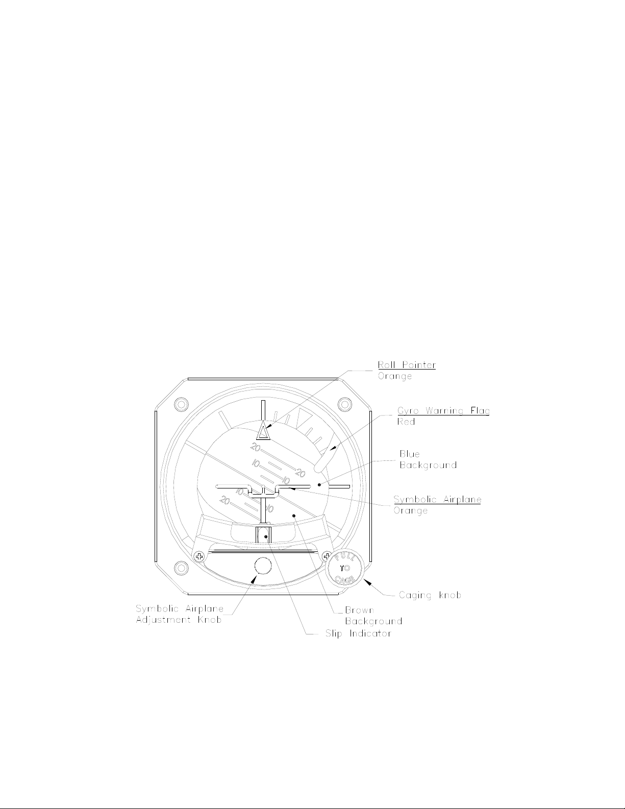
Roll Pointer: Fixed roll pointer: Indicates aircraft roll displacement relative to a
rotating roll dial.
Gyro Warning Flag: If loss of input voltage should occur, gyro warning flag will come into
view.
Display: Lower area of display, when referenced to the symbolic airplane,
indicates aircraft nose is below horizon or in a dive attitude. Upper area
of display indicates aircraft nose is above horizon or in a climb attitude.
Symbolic Airplane: Indicates roll and pitch attitude relative to the horizon. The symbolic
airplane can be moved (pitch only) using the symbolic airplane
adjustment knob.
Horizon Line: Indicates earth horizon relative to aircraft pitch and roll attitude.
Caging knob:
(Manual Erection)
Symbolic Airplane
Adjustment Knob:
When pulled, manually erects the gyro vertical to the case orientation.
Used to adjust the symbolic airplane.
Typical Electric Attitude Indicator Display
(Rotating Roll Dial, Fixed Roll Pointer, Traditional Wing Symbolic Airplane Shown)
Figure 1.1
REV B March 27, 2014 Manual Number 9016082 Page 7 of 13
Page 8

Mid-Continent Instruments and Avionics, Wichita, KS
Section 2: Installation
2.1 General
This section contains mounting, electrical connections and other information required for
installation. After installation of cabling and before installation of the equipment, ensure that
power is applied only to the pins specified in the interconnection diagram.
CAUTION: GYROS ARE DELICATE INSTRUMENTS! THE FOLLOWING PRECAUTIONS
MUST BE OBSERVED!!
A. A high gyroscope failure rate can be directly related to rough or improper handling.
Gyros are delicate and cannot withstand the shock of being dropped, jarred, or
struck by pieces of equipment. Do not place gyros on any hard surface. Pad with
generous foam. Handle like eggs!
B. To prevent damage to a gyro, the instrument should be transported to and from
the aircraft in it’s original shipping container. If this is impractical, the gyro should
be hand-carried carefully in an upright position.
C. A gyro should never be removed while it is spinning or running down. The instrument
normally operates at high RPM and may take 10 minutes or longer to run down. If it
is removed while running and tilted more than 20 degrees, the gyro can develop a
gimbal lock. The gimbal will tumble and start to spin. If gimbal lock occurs while the
rotor is turning, the gimbal may spin fast enough to damage the gimbal bearings,
requiring overhaul.
D. A malfunctioning gyro should be handled with the same care given a new
instrument. Most malfunctioning instruments can be repaired and returned to
service. Using proper handling procedures during removal prevents additional
damage and helps ensure possible reuse.
2.2 Pre-installation Inspection
A. Unpacking
Carefully remove Attitude indicator from shipping container. The shipping container
and packing materials should be retained for use should the attitude indicator require
future shipment.
B. Inspect for Damage
Inspect the shipping container and attitude indicator for any signs of damage
sustained in transit. If necessary, return attitude indicator to the factory using the
original shipping container and packing materials. File any claim for damages with
the carrier.
2.3 Parts
2.3.1 Installer Supplied Parts
A. Mounting Screw, 6-32UNC-2A. Three (3) required. (1” long screws are suggested for
panel thickness between 0.05 and 0.19, but may not be optimum in some
installations. The installer will need to determine what is correct for a particular
installation.) CAUTION: Do not exceed 1.06” screw depth into bezel!
B. Mating Connector, MS3116F8-4S or equivalent (P/N 9015514)
REV B March 27, 2014 Manual Number 9016082 Page 8 of 13
Page 9

Mid-Continent Instruments and Avionics, Wichita, KS
2.3.2 Additional Parts that may be required
A. Symbolic Airplane Adjustment Knob Cover Kit: (P/N 36022)
B. Slip Indicator Kit (P/N 36023)
C. Front Mount Kit: 3/32” thk (P/N 36028-1) or 1/2” thk (P/N 36027-1)
D. Panel Wedges: 3” (P/N PW3R-3) or 4” (P/N PW3R-4)
2.4 Equipment Location
The attitude indicator should be located within the aircraft in accordance with the following
considerations:
A. The indicator is ideally located in the instrument panel directly in line with the pilot’s
normal line of sight. The "PULL TO CAGE" knob should be within easy reach.
Installations that result in viewing angles in excess of 30 degrees may reduce display
readability.
B. Compare the space requirements of the indicator with the installation area being
considered.
C. The power cable should not run adjacent to heaters, engine exhausts, or other heat
sources. Also, take care to route and tie the cable away from aircraft controls and
cables.
2.5 Installation
NOTE: Before installing unit, verify the Options decal on the unit matches the aircraft
requirements for instrument voltage and panel tilt.
Install the Electric Attitude Indicator within the aircraft in accordance with the aircraft
manufacturer’s instructions and the following steps:
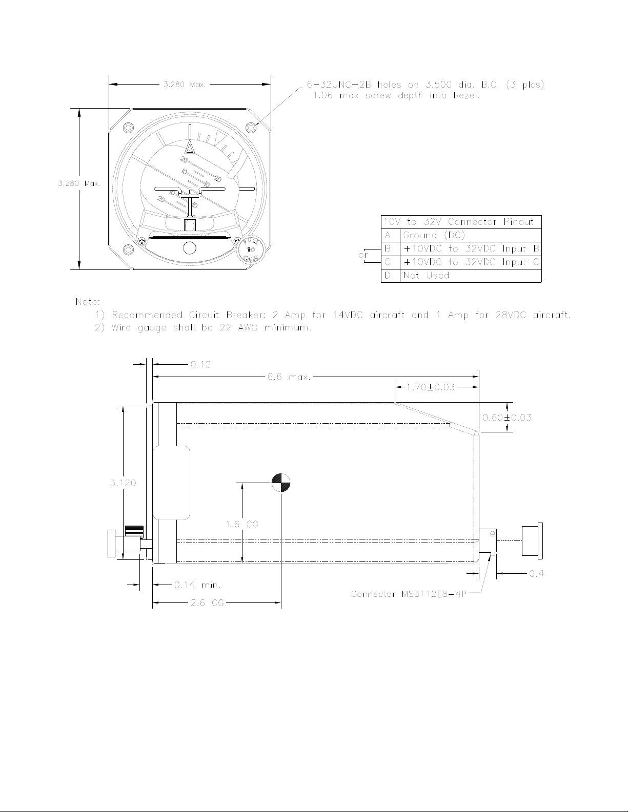
A. Refer to Figure 2.1 for installation dimensions and electrical information.
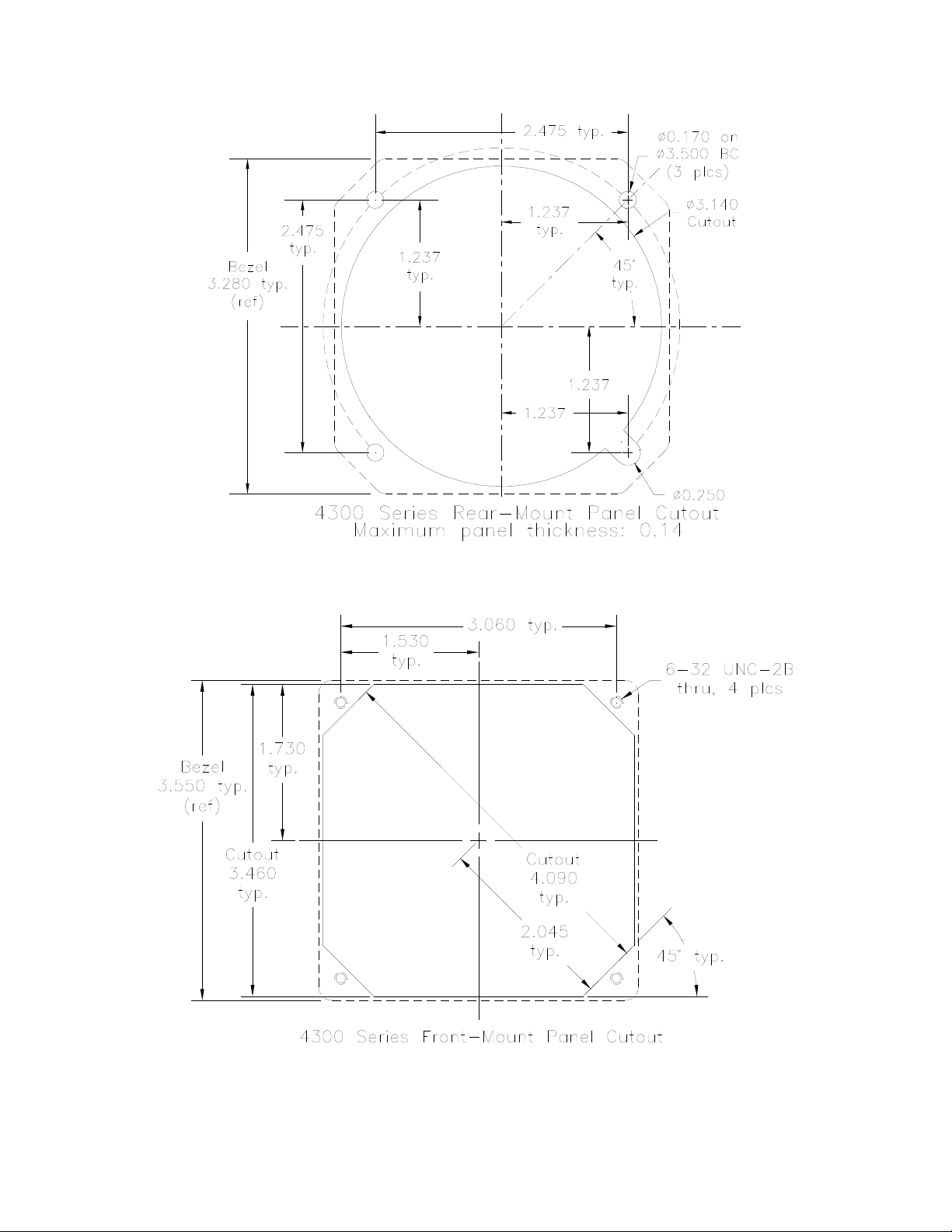
B. Ensure the available instrument panel cutout meets the requirements of the
indicator. See Fig 2.2 or Fig 2.3 for details.
C. Attach aircraft electrical system cable to indicator connector and insert the indicator
into the instrument panel cutout.
D. Secure the indicator to the instrument panel using the screw sizes called out in the
mounting instructions. Length of screws will be determined by aircraft instrument
panel thickness. The aircraft manufacturer or the installation facility is responsible
for supplying appropriate installation hardware.
E. Apply the correct input power to the indicator.
F. The Gyro Warning flag (red) will be out-of-view.
2.6 Continued Airworthiness
No periodic scheduled maintenance or calibration is necessary for continued airworthiness of the
4300 series Electric Attitude Indicator. If the unit fails to perform to specifications, it must be
removed and serviced by a qualified service facility.
REV B March 27, 2014 Manual Number 9016082 Page 9 of 13
Page 10
Mid-Continent Instruments and Avionics, Wichita, KS
Figure 2.1 Outline Drawing
REV B March 27, 2014 Manual Number 9016082 Page 10 of 13
Page 11
Mid-Continent Instruments and Avionics, Wichita, KS
Figure 2.2: Panel Cutout Dimensions
Figure 2.3: Front Mount Panel Cutout Dimensions
REV B March 27, 2014 Manual Number 9016082 Page 11 of 13
Page 12

Mid-Continent Instruments and Avionics, Wichita, KS
Section 3: Operation
3.1 General
This section describes the Model 4300-202/-203/-213 Electric Attitude Indicator operating
procedures. The indicator is required to be installed in an aircraft with the specified inputs
applied. Figure 1.1 provides an illustration of a typical Model 4300 display and a table describing
indicator functions.
3.2 Starting Procedures
The following operational procedures are recommended when preparing the indicator for use:
CAUTION: THE INDICATOR MAY BE DAMAGED IF THE “PULL TO CAGE” KNOB IS
RELEASED WITH A “SNAP.” RELEASE “PULL TO CAGE” KNOB AVOIDING A
“SNAP” RELEASE.
NOTE: Indicator may be momentarily caged by pulling “PULL TO CAGE” knob to the fully
extended position, holding knob until the display stabilizes, and then allowing the
knob to return to the normal position.
A. Apply power to the indicator. Note that the Gyro Warning flag (red) will pull out-of-
view. Also allow three minutes for presentation stabilization.
B. On models with trim adjustment, rotate the symbolic airplane adjustment knob for
the desired pitch attitude presentation, i.e. aligning the symbolic airplane with the
horizon.
C. If caging is required, caging should be accomplished when the aircraft is in a wings
level, normal cruise attitude, as indicated by other instruments or the horizon. If the
gyro is caged when the aircraft is not in this attitude, the resulting attitude
presentation immediately after caging will be in error by the difference between true
vertical and actual aircraft attitude. Small errors in caging erection will be corrected
by the indicator to true vertical in pitch and roll at 2.5 per minute minimum (5/min.
nominal).
3.3 In-Flight Procedures
A. Adjust the symbolic airplane to obtain desired pitch attitude presentation after take-
off.
B. In the event of errors in excess of 10 caused by extended bank or fore-aft
acceleration, the indicator should be momentarily caged after the aircraft is returned
to level flight.
3.4 Dynamic Errors
A. Turn Induced Errors
Pitch indication errors resulting from a standard coordinated turn (180 degrees in
one minute at a true airspeed of 156 knots) will not exceed 3. Dynamic errors
developed under non-standard conditions may be greater. Errors that develop will be
self corrected by the internal erection system or manually corrected by the actuation
of the caging system in straight and level flight.
REV B March 27, 2014 Manual Number 9016082 Page 12 of 13
Page 13

Mid-Continent Instruments and Avionics, Wichita, KS
B. Acceleration & Deceleration Errors
Pitch indicating errors may occur due to accelerations experienced during takeoff,
climb-out, descent, and landing. Errors that develop will be self-corrected by the
internal erection system or manually corrected (in straight and level flight) by the
actuation of the caging system.
C. Taxiing Errors
A pitch and roll indicator display error of approximately 1 will occur during a sudden
90 ground turn. A pitch indicator display error of approximately 2 will occur during
a sudden 180 ground turn. Errors that develop will be self corrected by the internal
erection system or manually corrected by the actuation of the caging system when
aircraft is straight and level.
3.5 EQUIPMENT LIMITATIONS
The 4300-202/-203/-213 series Electric Attitude Indicator is not to be used as a reference for
aerobatic flight. It is recommended to turn off the Attitude Indicator (red flag showing) at least 5
minutes before aerobatic maneuvers are initiated.
REV B March 27, 2014 Manual Number 9016082 Page 13 of 13
 Loading...