

Midco Unipower V4, Unipower V1, Unipower V2, Unipower V3, Unipower V5 Oem Installation & Start Up Instructions
...Page 1

OEM Installation & Start Up Instructions
C
O
M
P
A
N
Y
R
E
G
I
S
T
E
R
E
D
E
D
• In the United States, installation must conform with local
codes or in the absence of local codes, with the National
Fuel Gas Code, ANSI Z223.1-latest edition available from
American National Standard Institute. Further reference
should be made to the recommendation of your fuel supplier.
• In Canada, installation must conform with local codes or in
the absence of local codes, with Installation Codes for Gas
Burning Appliances and Equipment, Standard CAN/CGA
1-B-149.1 or 2.
• WARNING: Additions, changes, conversions and
service must be performed by an authorized Midco
representative, service agency or the fuel supplier. Use
only MIDCO specifi ed and approved parts.
• INSTALLER: Inform and demonstrate to the user the correct
operation and maintenance of the gas utilization equipment.
Inform the user of the hazards of storing fl ammable liquids
and vapors in the vicinity of this gas utilization equipment
and remove such hazards. Affi x this manual and associated
literature to the burner.
• CODE COMPLIANCE IS THE SOLE RESPONSIBILITY
OF THE INSTALLER.
Unipower VA Series
Variable Air Gas Burners
OEM Start Up
WARNING: If the information in these instructions
is not followed exactly, a fi re or explosion may result,
causing property damage, personal injury or death.
Do not store or use gasoline or other fl ammable vapors and
liquids in the vicinity of this or any other appliance.
WHAT TO DO IF YOU SMELL GAS:
• Do not try to light any appliance.
• Do not touch any electrical switch; do not use any
phone in your building.
• Immediately phone your gas supplier from another
building. Follow the gas supplier’s instructions. If
you cannot reach your gas supplier call the fi re
department.
Installation and service must be performed by a qualifi ed installer, service agency or the gas supplier.
BURNER MODEL: _____________________________________
BILL OF MATERIAL
NUMBER: ____________________________________________
SERIAL NUMBER #: ___________________________________
WIRING DIAGRAM: ___________________________________
FOR SERVICE CONTACT
Name: ____________________________________________
Address: ____________________________________________
____________________________________________
Phone: ____________________________________________
• USER: Retain this manual for future reference. If other
Date of Installation: ___________________________________
than routine service or maintenance as described in this
manual and associated literature is required, contact a
qualifi ed service agency. DO NOT ATTEMPT REPAIRS.
An inadvertent service error could result in a dangerous
condition.
AVOID ERROR IN PARTS SELECTION. When ordering use
complete MIDCO Part Number and Description. Furnish Burner
Model Number, Bill of Material Number and Serial Number (if
available) from the specifi cation plate found on the product
IMPORTANT: Availability of parts as well as specifi cations are
subject to change without notice. Please consult factory for item
availability.
SAFETY INFORMATION TERMS: The following terms are used to identify hazards, safety precaution of special
notations and have standard meanings throughout this manual. They are printed in all capital letters using a
bold type face as shown below, and preceded by the exclamation mark symbol. When you see the safety alert
symbol and one of the safety information terms as shown below, be aware of the hazard potential.
Midco® International Inc.
4140 West Victoria Street
Chicago, Illinois 60646
toll free 866.705.0514
tel 773.604.8700
fax 773.604.4070
web www.midcointernational.com
e-mail sales@midcointernational.com
CAUTION: Identifi es unsafe practices which would result in minor personal injury or
product and property damage.
DANGER: Identifi es the most serious hazards which will result in severe personal injury or death.
WARNING: Signifi es a hazard that could result in personal injury or death.
Quality Designed for Proven Performance
U
C
LISTED
IHEA
L
US
®
Member
8478 00
Printed in USA
619
Page 2
Installation - Speci cations
Specifi cations 1
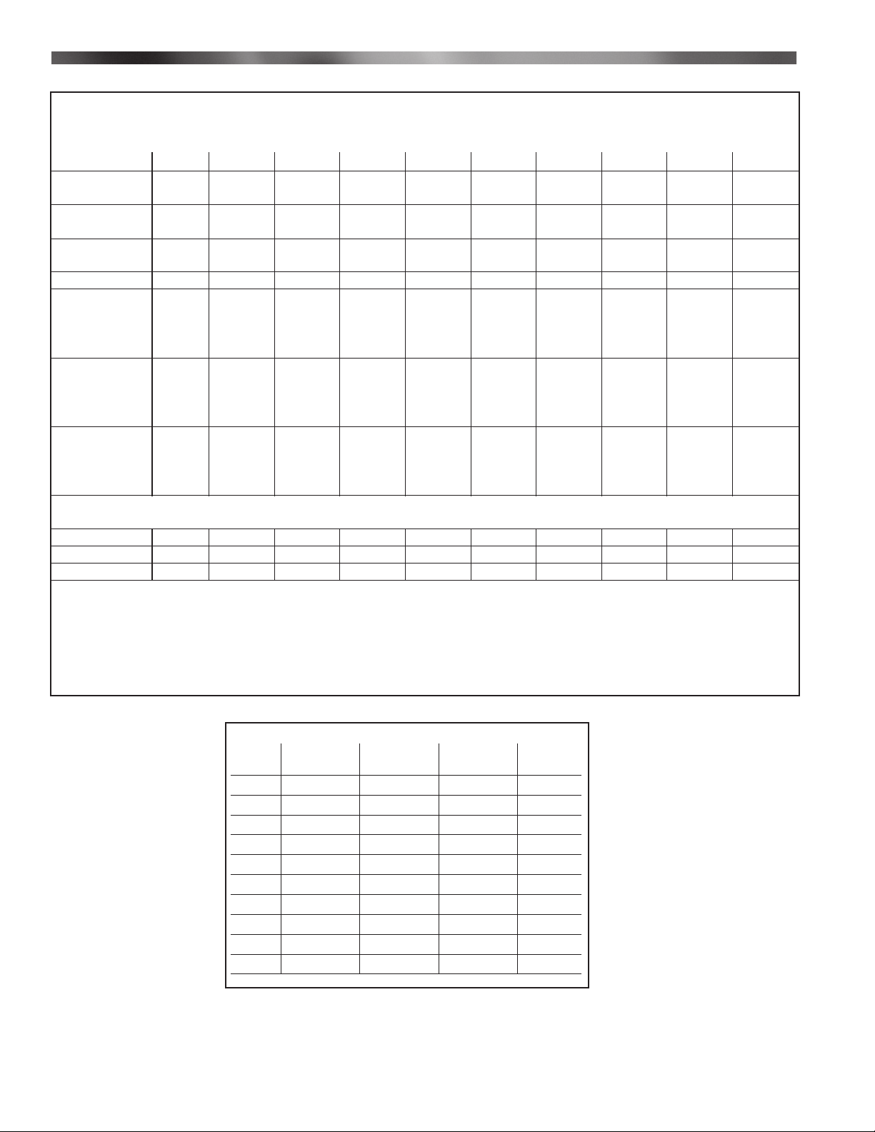
The VA Series, Models V1 to V 6 burners with intermittent spark ignited pilots and V7 to V10 with interrupted pilots are adaptable
to most gas utilization equipment, including gravity and forced circulation furnaces, heat exchangers and process ovens. They are
particularly recommended for fi ring high effi ciency and high turndown applications.
Burner Model V1 V2 V3 V4 V5 V6 V7 V8 V9 V10
Maximum Input
at 10″
(MBH/hr)
Maximum Input
at 7″
(MBH/hr)
Minimum
Input
(MBH/hr)
Turndown 19-1 26-1 25-1 25-1 25-1 25-1 24-1 24-1 25-1 25-1
Inlet Gas
pressure for
maximum
fi ring rate
Manifold gas
pressure for
maximum
fi ring rate
Approximate
Air Delivery at
Zero Draft
2,3
670 1,260 2,000 2,000 2,500 2,500 3,000 3,000 3,800 3,800
2,3
550 1,150 1,890 1,890 2,500 2,500 3,000 3,000 3,300 3,330
2,3
36 48 80 80 100 100 120 120 150 150
4
(NG) 10.0″ 10.0″ 10.0″ 10.0″ 10.0″ 10.0″ 10.0″ 10.0″ 10.0″ 10.0″
(NG) 5.0″ 3.4″ 3.9″ 3.9″ 4.3″ 4.3″ 4.4″ 4.4″ 4.9″ 4.9″
(CFM) 115 210 360 360 440 440 620 620 720 720
Minimum Recommended Chamber Size
Width 18 24 34 28 42 30 48 36 54 36
Height 18 24 26 28 26 36 28 42 28 42
Depth 42 48 54 54 60 60 66 66 72 72
1
Standard burners are shipped as NATURAL gas models. Contact Midco for PROPANE gas burners.
2
1 MBH = 1,000 Btu/hr
3
All Ratings Based on 1000 BTU/Cu. Ft. NATURAL, 2500 BTU/Cu. Ft. PROPANE at sea level. Derate burner for altitude over 2,000 feet by 4%
for each 1,000 feet above sea level.
4
Lower gas inlet pressure may be used when maximum input is not required. Burner input based on 0.5″ W.C. back pressure.
Table 1. Burner Specifi cations
Burner Control Motor TOTAL Motor
Model amps amps amps HP
V1 1.3 3.5 4.8 .32
V2 1.6 4.0 6.8 .50
V3 1.5 10.5 12 1.10
V4 1.5 10.5 12 1.10
V5 2 10.5 12.5 1.10
V6 2 10.5 12.5 1.10
V7 2.1 13 15.1 1.75
V8 2.1 13 15.1 1.75
V9 2.1 13 15.1 1.75
V10 2.1 13 15.1 1.75
2
Midco International Inc.
8478 00
Page 3
Installation - Startup Adjustment
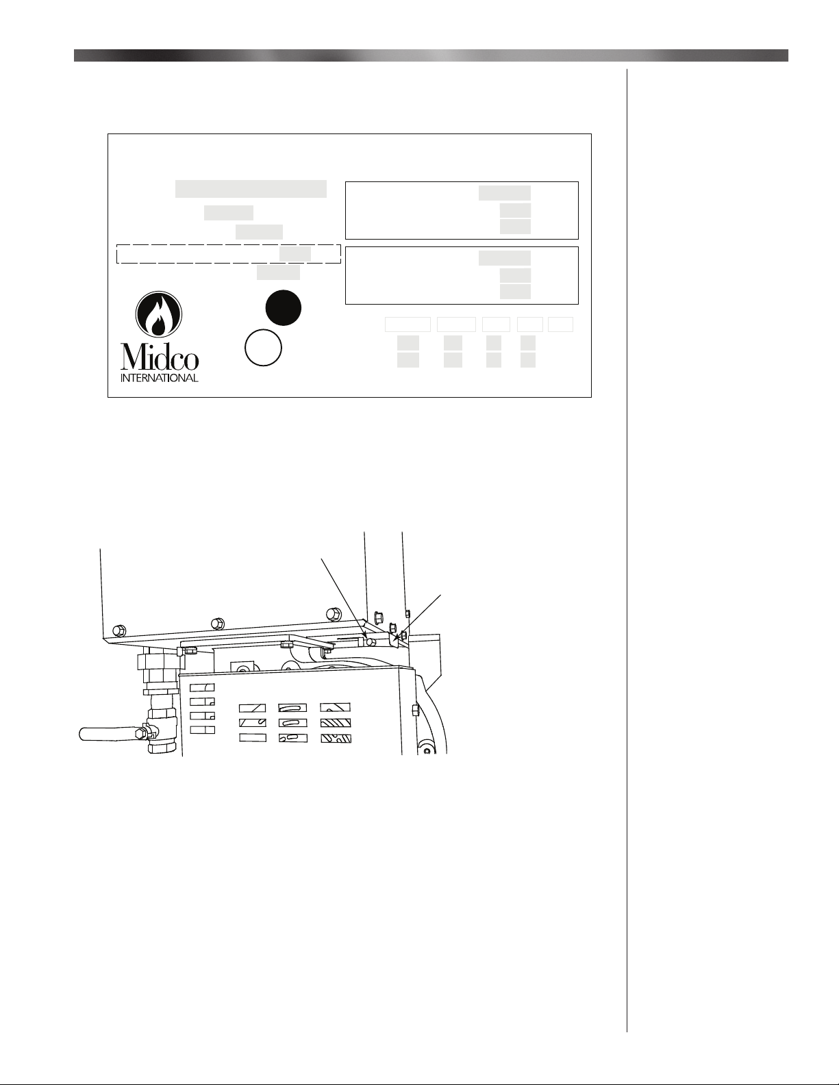
- Before opening the main supply gas valve, see Figure 3 - item # 9, verify that the inlet
pressure is below the maximum inlet pressure specifi ed on the Burner Rating Label,
see Figure 1.
- Exposing components to pressure above the maximum inlet pressure can cause damage.
®
UNIPOWER VA Gas Burner
MODEL:
SERIAL NO.:
BILL OF MATERIAL:
MAXIMUM INLET PRESSURE: W.C.
Î
MINIMUM FIRING RATE: BTU/HR
NAT
®
CHICAGO, IL 60646
Figure 1. Burner Rating Label - Maximum Inlet Pressure
_____________________________________
U
®
L
C
LISTED
No. Pl-100, 058
US
FIRING RATE: BTU/HR
PRESSURE REQUIRED: W.C.
MANIFOLD PRESSURE: W.C.
MAX. CAPACITY: BTU/HR
PRESSURE REQUIRED: W.C.
MANIFOLD PRESSURE W.C.
VOLTS
CONTROLS
MOTOR
AMPS HZ PH HP
7”
10”
2121-07
I
Confi rm Inlet Pressure
- Confi rm that the air damper, see Figure 2, is completely open and has not been
inadvertently moved during packing, shipping, or installation.
- To open, loosen the nut that secures the damper and pull it outward. Then retighten
the nut.
Slide
Loosen the Nut
Outward
to Open
Figure 2. Air Damper
_____________________________________
II
Check Air Damper
8478 00
Midco International Inc.
3
Page 4
Installation
Install Shut-Off Type
Pressure Fittings
III
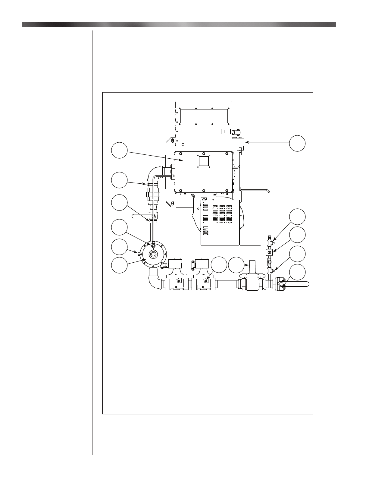
- Install the necessary fi ttings so that pressure can be measured at fi ve points
listed below ...
Refer to Figure 3:
a. Manifold pressure - item # 2
b. Load line pressure - item # 4
c. Main gas regulator outlet pressure - item # 7
d. Inlet pressure - item # 10
e. Pilot pressure - item # 12
1
2
13
3
4
5
6
7
8
Item # Description
1. Back Plate
2. Main Gas Manifold Pressure Tap
3. Manual Firing Valve
4. Load Line Pressure Tap
5. Low Fire Bypass
6. Ratio Regulator
7. Main Gas Regulator Outlet Pressure Tap
8. Main Gas Regulator
9. Main Supply Gas Valve
10. Inlet Gas Pressure Tap
11. Pilot Gas Regulator
12. Pilot Gas Manifold Pressure Tap
13. Pilot Solenoid Valve
12
11
10
9
Figure 3. Component and Pressure Tap Locations
_____________________________________
4
Midco International Inc.
8478 00
Page 5

Installation
- Close manual fi ring valve - see Figure 3, item # 3
- Open main Supply gas valve - see Figure 3, item # 9
- Initiate burner operation
a. The following are required to initiate burner operation:
1. 120V AC power supply
2. The on/off switch on the front of the burner needs to be in the on position
3. There needs to be at least a 2.0V DC signal from a temperature control or a
DC Volt generator.
b. The call for heat signal needs to be closed. With a call for heat the burner will
enter Purge Mode - see page 8, SCEBM-2 Module, paragraph a.
c. After the purge time specifi ed by the control the burner will attempt to ignite the
pilot
d. After the pilot is established, the burner will ignite the main fl ame
e. When the main fl ame ignites the burner will be in Run Mode
_____________________________________
- Use a manometer to check the pilot pressure on the tee downstream of the pilot
regulator, see Figure 4 - item # 2.
- For intermittent pilot systems
a. 3.2″ to 3.5″ W.C. pressure (internal pilot).
- For interrupted pilot systems
a. 1.5″ to 2.0″ W.C. pressure (external pilot ).
- Note: If adjustment is necessary the adjustment must be made while the pilot solenoid
valve is open and pilot gas is fl owing. Keep in mind that on interrupted pilot systems
the pilot solenoid valve closes after a set period of time after the main gas is turned on.
IV
Ignite Burner Pilot
V
Adjust Pilot Pressure
1
2
3
1. Pilot Pressure Regulator
2. Pilot Pressure Tap
3. Inlet Gas Pressure Tap
Figure 4. Pilot Gas Pressure Tap and Regulator
_____________________________________
- Open Manifold Gas Shut-off Valve, see Figure 3 - item # 3
- Adjust the input signal to 2.0V DC
- Use the sight glass on the back plate of the burner to look at the low fi re. If light
is visible through all of the holes in the burner plate, the low fi re is set within the range
of operation of the burner. If light is not visible coming through all of the holes, then the
low fi re is too low and the low fi re bypass located on the side of the ratio regulator, see
Figure 3 - item # 5, needs to be opened (counter-clockwise to open, clockwise to close).
_____________________________________
- Use a manometer to check the inlet pressure on the tee on the upstream side of the pilot
regulator, see Figure 4 - item # 3.
- Use another manometer to check the main gas regulator outlet pressure on the upstream
side of the most upstream solenoid valve, see Figure 3 - item # 7.
- Turn the burner up to its actual fi ring rate applying an input signal of 10V DC for maximum
fi ring rate
- Confi rm that the inlet pressure remains between the maximum and minimum values
specifi ed on the Burner Rating Label, see Figure 5.
8478 00
Midco International Inc.
VI
Adjust Low Fire
VII
Adjust the Main Gas
Regulator
5
Page 6

Installation
Adjust the Main Gas
Regulator
Continued
- The main gas regulator outlet pressure should be 1″ W.C. lower than the minimum
VII
pressure required fi gure on the Burner Rating Label.
a. When “Pressure Required” is 7.0″ set the main gas regulator outlet pressure at 6.0″
b. When “Pressure Required” is 10.0″, set the main gas regulator outlet pressure at 9.0″
UNIPOWER VA Gas Burner
®
VIII
Verify the Ratio
Regulator Adjustment
MODEL:
SERIAL NO.:
BILL OF MATERIAL:
MAXIMUM INLET PRESSURE: W.C.
Î
MINIMUM FIRING RATE: BTU/HR
FIRING RATE: BTU/HR
PRESSURE REQUIRED: W.C.
MANIFOLD PRESSURE: W.C.
MAX. CAPACITY: BTU/HR
PRESSURE REQUIRED: W.C.
MANIFOLD PRESSURE W.C.
Î
NAT
CHICAGO, IL 60646
®
U
®
L
C
LISTED
No. Pl-100, 058
US
VOLTS
CONTROLS
MOTOR
AMPS HZ PH HP
2121-07
Figure 5. Burner Rating Label - Maximum and Minimum Pressure Required
_____________________________________
- Use a manometer to check the manifold pressure near where the valve train attaches to
the burner, see Figure 3 - item # 2.
- Use another manometer to check the load pressure on the ratio regulator, see
Figure 3 - item # 4.
- Modulate the burner until the load line pressure is 2.0″ W.C. by adjusting the input voltage
to the burner. See page 9, Figure 8 for manual adjustments.
- Verify that the manifold pressure is within the values given in Table 2.
- If necessary turn the screw on the ratio regulator, see Figure 4, in order to adjust
the manifold pressure.
Model Pressure
V1-V4 0.8-0.9″ W.C.
V5-V6 0.2-0.3″ W.C.
V7-V10 0.5-0.6″ W.C.
Table 2.
Figure 4. Ratio Regulator
_____________________________________
6
Midco International Inc.
8478 00
Page 7

Installation
Note: Burners are not always set up to maximum capacity. Refer to the “Firing Rate” portion of
the Burner Rating Label or the Label of the heating equipment for the actual fi ring rate.
- Modulate the burner to high fi re by applying a 10V DC input signal. See page 9, Figure 8
for manual adjustments.
- Verify that the manifold pressure is the same as marked on the Burner Rating Label(s) for
the actual fi ring rate.
- If necessary adjust the fHi (fan high) setting on the SCEBM-2 module until the desired
manifold pressure is achieved. Use Figure 7 to determine desired manifold pressure.
a. For information on how to adjust the fHi setting refer to page 9, the SCEBM-2 Module
section of this manual.
Manifold Pressure vs. Firing Rate - VA Burners
5
V1
4.5
V5 - V6
V3 - V4
Manifold
Pressure
(Inches W.C.)
3.5
2.5
4
V2
3
2
IX
Verify High Fire Input
Adjustment
V9 - V10V7 - V8
1.5
1
0.5
0
0 350030002500200015001000500
_____________________________________
- Use a combustion analyzer to confi rm that the high fi re oxygen (O
3.0 to 5.0% and the carbon dioxide (CO2) level is between 8.5 to 10.0%. The carbon
Firing Rate (mbtu/hr)
Figure 7.
) level is between
2
monoxide (CO) should be less than 100 ppm while the fl ue gas temperature should be
below 550° F.
- Confi rm that at low fi re the oxygen level is between 16.0 to 18.5% and the carbon
monoxide (CO) level is less than 400 ppm corrected to 3% O
_____________________________________
.
2
- Remove call for heat (open heat enable contact).
- Close main supply gas valve, see Figure 3 - item # 9.
- Turn off main power disconnect and burner control panel switch.
- Remove pressure tap fi ttings and gauges for pressure measurements. Replace pipe plugs.
- Reinstall the caps to the pilot regulator, main regulator, low-fi re bypass and ratio regulator.
_____________________________________
4000
X
Check Emissions
XI
Shut Down
- Open all manual gas valves
- Turn on power at disconnect switch
- Turn on power switch on burner control panel door
- Set heat enable and temperature controller to desired operating condition and temperature
- Burner will start and operate based on 2 to 10V DC analog input provided
_____________________________________
8478 00
Midco International Inc.
XII
Normal Operation
7
Page 8

Installation - SCEBM-2 Module
SCEBM-2 Module is designed to control the speed of the combustion blower based on three input
I
SCEBM-2 Module
signals and several programmable parameters.
- The inputs
a. 2-10V DC control signal
i. Controls the speed of the combustion blower whenever the burner is in run mode.
ii. Also, there needs to be at least 2.0 V DC signal to this input in order for the burner to
turn on.
b. Main valve input
i. When power is supplied to the main valves it is also supplied to the SCEBM-2 control.
Along with the pilot valve input, this determines what mode the burner is in.
c. Pilot valve input
i. When power is supplied to the pilot valve(s) it is also supplied to the SCEBM-2 control.
Along with the main valve input, this determines what mode the burner is in.
Inputs
Application Pilot Main Display Relay PWM Output
Intermittent Off Off PRGE Open 100%
Pilot On Off PIL Closed Min
VA-A On On RUN Open Modulate
Off On ERR Open Min
Interrupted Off Off PRGE Open 100%
Pilot On Off PIL Open Min
VA-B On On IGN Open Min
Off On RUN Open Modulate
Accessing the
Program Menu
PRGE=Purge mode. Before the burner starts or after the burner
stops the combustion blower is modulated to high speed to purge the
combustion chamber with air.
PIL=Pilot mode. The period where the pilot valve is on but the main
valve is not on yet during which the pilot fl ame is established. In this
mode the combustion blower is modulated to low speed.
IGN=Ignition mode. On interrupted pilot systems, the time where both
valves are open is the period where the main fl ame is ignited by the
pilot fl ame. During this time the combustion blower will remain at low
speed.
RUN=Run mode. After the ignition sequence is complete, the burner will
be in run mode. Only in this mode will the combustion blower modulate
based on the 2-10V DC temperature control signal.
Table 3.
_____________________________________
II
- Refer to the Figure 8, page 9, for an overview of the program menu. To enter the program
menu, hold the enter key down for 3 seconds until “APP” is displayed. Use the up and
down arrow keys to navigate to the desired parameter as shown in column 1. To
edit a menu parameter, press the right arrow key once on the desired parameter. The
current value of the parameter will be displayed. Use the up and down arrow keys again to
edit the parameter. Press the enter key to save changes made or press the left arrow key
to cancel without saving and return to column 1. If a key is not pressed for 20 seconds or
the enter key is held for 3 seconds while in program mode, the control will return to normal
mode.
8
Midco International Inc.
8478 00
Page 9

Installation - SCEMB-2 Module
p
(
play
SCEBM-2 Menu Map
What you want to do What you see What it means
Column 1 Column 2
Control applications for Variable Air or NOX
Set the lowest the user can adjust the
temperature to in normal mode for setpoint.
Set the highest the user can adjust the
temperature to in normal mode for setpoint.
Set the minimum percentage the user can adjust
the Fan to in normal mode
Set the maximum percentage the user can adjust
the Fan to in normal mode
Control input modes
Override allows the user to manually control the
ercentage
Fan
Select the desired aggression/speed of the PID
curve for the valve
Set a temperature offset. For examples, to correct
for duct losses or sensor calibration errors.
Set the control to convert the temperature to
either °F or °C.
dis
The password may either be enabled or disabled.
View the software version number.
Standard, Low, or High).
DN
PASS
DN
APP
tLo
thi
FLo
Fhi
inPt
ovEr
Pid
oFS
ForC
vEr
P
P
LT RT
ENT
vA-A
vA-b
noX
40
90
10
100
dC
rE
tS
dAbL
EnAb
Lo
Std
° F
° C
dAbL
EnAb
1.0
Column 1 shows the menu parameters
Column 2 shows the factory set defaults for each
parameter. Temperature defaults are shown in °F.
Arrow Keys:
Up and Down: to navigate or adjust a menu parameter
Right: to access column 2 for editing a parameter
Left: to return to column 1 without saving a parameter
Enter: to return to column 1 with saving a parameter
Low (tLo) can be set from 40°F - 240 °F and must be at
least 10°F less than the High. High (thi) can set be from
50°F - 250°F and must be at least 10°F greater than the
Low. These will limit how far the user can change the
temperature outside of programming mode.
Setpoint may be adjusted on the main screen with the
up and down arrows, then pressing enter to save the
selected setpoint.
hi
Applications (APP):
VA-A is the intermittent piloted burners
VA-B is burners with an interrupted pilot
0
NOX is for low nox burners
Input (inPt) modes:
dC: Allows the user to directly control the fan speed
with a 2-10V input
rE: Allows the user to use an external remote 2-10V
input
tS: Allows the user to use the built-in onboard setpoint
and ignores the 2-10V input
UP
LT
ENT
RT
DN
Figure 8.
_____________________________________
- There are several parameters that can be adjusted for the specifi c application. The
adjustable parameters are as follows.
- APP
a. Determine the functionality of the inputs by specifying which type of burner the control
is being used on.
b. VA-A is for VA series burners that use an intermittent pilot
c. VA-b is for VA series burners that use an interrupted pilot
d. NOx is for Midco Low-NOx series burners
8478 00
Midco International Inc.
III
Setting the Parameters
9
Page 10

Installation - SCEMB-2 Module
III
Setting the Parameters
Continued
- tLo and thi
a. Use these parameters to adjust the minimum and maximum temperature set point that
a user can set while outside of programming mode.
b. NOTE: These parameters only have an eff ect on the operation of the burner when the
burner is operated by temperature control. See section inPt below.
- FLo and Fhi
a. Use these parameters to adjust the minimum and maximum speed that the
combustion blower can achieve (displayed as a percentage of the maximum capacity
of the blower).
b. Adjusting FLo will change the speed of the combustion air blower during ignition and
when in run mode at 2.0V DC. This eff ectively changes the minimum fi ring rate. The
default setting is 10% of maximum fan speed.
c. Adjusting Fhi will change the speed of the combustion air blower while in run mode
with a 10.0V DC input signal. This eff ectively changes the maximum fi ring rate of the
burner. The default setting is 100% of maximum fan speed.
- inPt
a. The inPt (input) parameter is used to specify which type of input is used to control the
modulation of the burner.
b. DC is for using a 2-10V DC input signal sent from an external temperature controller.
c. tS is the setting used when one connects a discharge temperature sensor directly
to the SCEBM-2 module. The SCEBM-2 then modulates the burner based on the
discharge temperature and the temperature set point.
d. rE is used when one connects a discharge temperature sensor as well as an external
thermostat. The SCEBM-2 still modulates the burner based on the discharge
temperature and the temperature set point, but in this mode the temperature set point
is set from an external device.
- ovEr
a. Enables or disables the manual override function. When enabled, the user can adjust
the combustion fan speed manually using the up and down arrows. The input signal
from the external temperature controller or the discharge temperature sensor will be
overridden.
- Pid
a. The Pid parameter is used to adjust how aggressively the SCEBM-2 module tracks
the discharge temperature. NOTE: This parameter only has an eff ect on the operation
of the burner when the burner is operated by temperature control.
- oFS
a. The oFS (off set) parameter is used to adjust the discharge air sensor. NOTE: This
parameter only has an eff ect on the operation of the burner when the burner is
operated as a temperature control.
- ForC
a. This parameter is used to choose whether the SCEBM-2 module displays the
temperature in degrees Fahrenheit or degrees Celsius. NOTE: This parameter only
has an eff ect if there is a temperature discharge sensor hooked up to the SCEBM-2
- PASS
a. The user can use this parameter to enable or disable the password. If the password is
enabled, one must enter it in order to access the program menu.
- vEr
a. The installed version of the software.
10
Midco International Inc.
8478 00
Page 11

8478 00
Midco International Inc.
11
Page 12

12
Midco® International Inc. - 4140 West Victoria Street - Chicago, Illinois 60646 - toll free 866.705.0514
tel: 773.604.8700 - fax: 773.604.4070 - web: www.midcointernational.com - e-mail: sales@midcointernational.com
G
E
R
ISO
9001
C
O
T
S
E
I
R
N
M
A
P
E
D
Y
Printed in USA
619
8478 00
 Loading...