

Page 1
Installation and Service Instructions
608
8471 50
Printed in U.S.A.
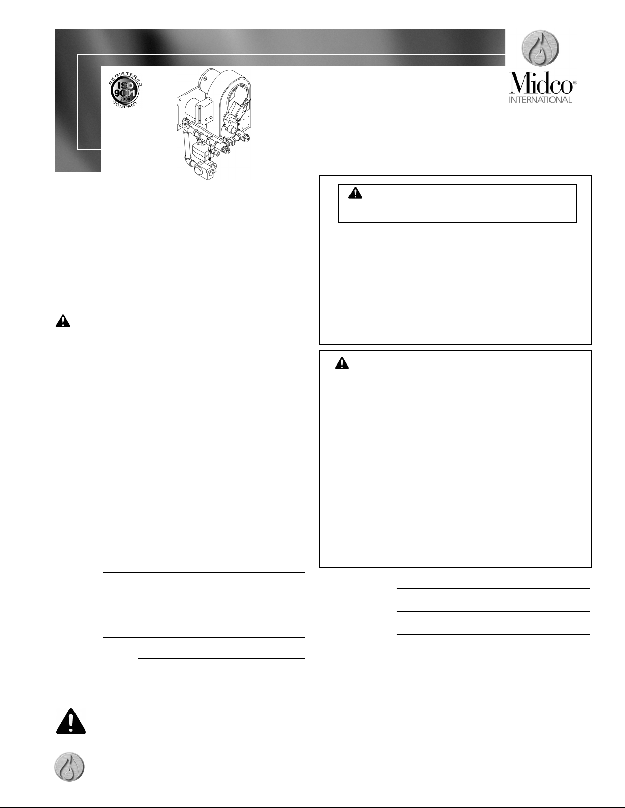
Economite
RE4400DS HTD
Gas Burner
Midco®International Inc.
4140 West Victoria St. - Chicago, Illinois 60646
tel 773.604.8700 fax 773.604.4070
web www.midcointernational.com e-mail sales@midcointernational.com
Quality Designed for Proven Performance
In the United States, Installation must conform
with local codes or, in the absence of local codes, with
Installation of the National Fuel Gas Code, ANSI Z223.1-
latest edition, from the American National Standard Institute.
Further reference should be made to the recommendation of
your fuel supplier.
In Canada, Installation must conform with local
codes or, in the absence of local codes, with Installation
Codes for Gas Burning Appliances and Equipment, CGA
Standard CAN/CGA 1B-149. Further reference should be
made to the recommendation of your fuel supplier.
WARNING: Additions, changes, conversions, and
service must be performed by an authorized MIDCO
representative, service agency, or the fuel supplier. Use
only MIDCO specified and approved parts.
INSTALLER: Inform and demonstrate to the user the
correct operation and maintenance of the gas utilization
equipment. Inform the user of the hazards of storing
flammable liquids and vapors in the vicinity of this gas
utilization equipment and remove such hazards. Affix
this manual and associated literature adjacent to the
burner. CODE COMPLIANCE IS THE SOLE
RESPONSIBILITY OF THE INSTALLER.
USER: Retain this manual for future reference. If other
than routine service or maintenance as described in this
manual and associated literature is required, contact a
qualified service agency. DO NOT ATTEMPT REPAIRS.
An inadvertent service error could result in a dangerous
condition.
FOR SERVICE CONTACT:
Name
Address
Phone
Date of Installation
Do not store or use gasoline or other flammable vapors and
liquids in the vicinity of this or any other appliance.
WHAT TO DO IF YOU SMELL GAS:
Do not try to light any appliance.
Do not touch any electrical switch;do not use any
phone in your building.
Immediately phone your gas supplier from another
building. Follow the gas supplier’s instructions. If you
cannot reach your gas supplier call the fire department.
Installation and service must be performed by a
qualified installer, service agency or the gas supplier.
WARNING: If the information in these instructions
is not followed exactly, a fire or explosion may result,
causing property damage, personal injury or death.
Burner Model
Bill of Material #
Serial Number
Wiring Diagram
AVERTISSEMENT. Assurez-vous de bien suivre
les instructions données dans cette notice pour
réduire au minimum le risque d’incendie ou
d’explosion pouvant entraîner des dommages
matériels, des blessures ou la mort.
S A F E T Y I N F O R M A T I O N T E R M S : The following terms are used to identify hazards, safety precaution of special
notations and have standard meanings throughout this manual. They are printed in all capital letters using a bold type face
as shown below, and preceded by the exclamation mark symbol. When you see the safety alert symbol and one of the
safety information terms as shown below, be aware of the hazard potential.
DANGER: Identifies the most serious hazards which will result in severe personal injury or death.
WARNING: Signifies a hazard that could result in personal injury or death.
CAUTION: Identifies unsafe practices which would result in minor personal injury or product and property damage.
Ne pas entreposer ni utiliser d’essence ni d’autres
vapeurs ou liquides inflammables à proximité de cet
appareil ou de tout autre appareil.
QUE FAIRE SI VOUS SENTEZ UNE ODEUR DE GAZ:
• Ne pas tenter d’allumer d’appareil.
• Ne touchez à aucun interrupteur. Ne pas vous servir des
téléphones se trouvant dans le bâtimentoù vous êtes.
• Appelez immédiatement votre fournisseur de gaz depuis
un voisin. Suivez les instructions du fournisseur.
• Si vous ne pouvez rejoindre le fournisseur de gaz,
appelez le service des incendies.
L’installation et l’entretien doivent être assurés par un
installateur ou un service d’entretien qualifié ou par le
fournisseur de gaz.
Page 2
Part 1 Installation
Specifications
The ECONOMITE Model RE 4400DS HTD (High Turn Down) burners with direct spark
ignition are adaptable to most gas utilization equipment.
AIR DELIVERY (Approximate Air Delivery at Zero Draft)
RE4400DS HTD ..... 87 SCFM
1
FIRING RATE (NATURAL )2 (Based on 0 draft over fire pressure)
MAXIMUM MBH
3
400
MINIMUM MBH
3
20
GAS SUPPLY PRESSURE REQUIRED Min Max
250 MBH ................................................... 7.0" to 14.0" W.C
350 MBH ................................................... 7.0" to 14.0" W.C
400 MBH ................................................... 7.0" to 14.0" W.C
TUBE DIAMETER ........................................................... 4"
RECOMMENDED COMBUSTION CHAMBER SIZE (AT MAX. BTU/HR)
WIDTH 10"
LENGTH 16.5"
ELECTRICAL SUPPLY
4
.....................................120/208/230 VAC...........60 Hertz
ELECTRONIC CONTROL VOLTAGE ................ 24 VAC
FLAME SAFETY....Direct Spark Ignition of Main Flame, Electronic Safety
TABLE 1: Burner Specifications
1. SCFM = Standard Cubic Feet / Minute.
2. All Ratings Based on 1000 BTU/Cu. Ft. NATURAL Derate burner for altitude over 2,000 feet by
4% for each 1,000 feet above sea level.
3. 1 MBH = 1,000 BTU/hr.
4. Burners available in 115V, 208V or 230V power supply. Consult burner name plate for correct
power supply, or as recommended by the equipment manufacturer.
____________________________
The burner tube, or the stainless steel sleeve that is included with the burner, must be
sealed air tight into the combustion chamber opening with refractory material. The sleeve is
preferred as it is designed to properly locate the end of the tube relative to the inside wall of
the combustion chamber, and to permit burner removal
or as recommended by the equipment
manufacturer
.
CAUTION: In no case should the burner tube be allowed to extend into the
chamber because high combustion chamber temperatures will cause premature
electrode, burner tube and sleeve deterioration.
____________________________
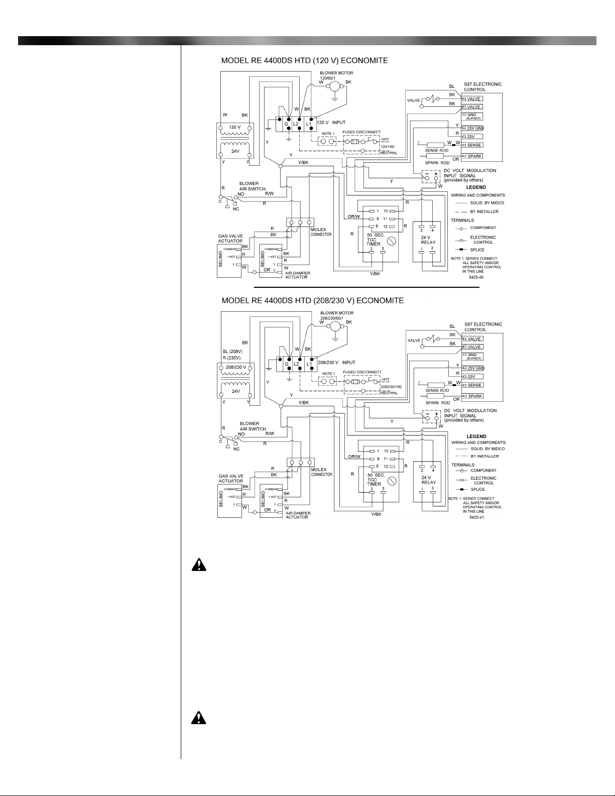
CAUTION: Refer to wiring diagram in Figure 1 or located on the burner
housing.
Installation wiring and grounding to the burner must conform to local codes, or, in their
absence in the United States to National Electric Code, ANSI/NFPA No. 70 latest edition;
in Canada, to Canadian Electrical Code Part 1, CSA Standard C22.1
Use copper wire not less than 14 gage for line voltage wiring. Hook up to a dedicated line
with an on-off disconnect switch and a minimum 10 Amp breaker, or as required by
equipment manufacturer.
The frame of the burner should be well grounded. A ground lug is located in control box
for positive grounding where insulated pipe couplings are used or where any doubt exists
regarding grounding sufficiency.
Confirm that the polarity is correct—hot wire to strip terminal L1, neutral L2—and that the
neutral line is not subject to induced low voltage (check L2 to earth ground) from other
equipment, as that can cause the Electronic Control to malfunction.
Each installation must include suitable limit control(s).
CAUTION: Label all wires prior to disconnection when servicing controls.
Wiring errors can cause improper and dangerous operation. Verify proper operation
after servicing.
Part 1
Installation
2
I Combustion
Chamber
II Electrical
Page 3
____________________________
CAUTION: The available gas pressure should be within the limits shown in
Table 1 - SPECIFICATIONS section. Excessive pressure may damage electric valves,
regulators and manual valves. If the supply pressure exceeds the 14.0"W.C. maximum,
a suitable high pressure regulator must be installed between the Main Manual
Shut-Off Valve and burner combination valve.
The burner gas supply piping should branch off from the main line as close to the gas
meter as possible. Do not connect to the bottom of a horizontal section. Use new black pipe
and malleable fittings free of cutting and threading burrs or defects.
Piping must also comply with your local codes.
To obtain the maximum firing rate of the burner, the gas supply piping must be sized to
provide a minimum pressure of 7.0"W.C. (Natural) for 400 MBH to the inlet of the combination
redundant valve when the burner and all other gas utilization equipment are on refer to table
# 3 for 350 MBH and 250MBH gas pressure requirements. The main regulator, if equipped,
should be mounted upright and in a horizontal run of pipe, refer to regulator manufacturer’s
installation instructions.
CAUTION: Because it is difficult to accurately control pressure during supply
pipe leak testing, it is recommended that all low pressure 1/2 PSIG (14.0"W.C. max.)
components be disconnected during testing. Exposing low pressure regulators and
valves, including manual valves, to pressures over 1/2 PSIG (14.0"W.C.) will cause
damage and void all warranties.
3
Part 1
Part 1 Installation
Figure 1: Wiring Diagrams
II Electrical
Continued
III Piping
Page 4

DANGER: Explosion hazard.
Do not use oxygen for pressure testing.
An explosion could occur during initial start up.
If the burner piping must be rearranged because of space limitation, be sure to carry out
the general arrangement shown in Figure 2. Install the combination valve in any position
except up-side down.
When the burner is installed in the vestibule of jacketed equipment, it is recommended
that the Automatic Safety Shut-Off Valve be left adjacent to the burner within the vestibule
and the Main Manual Shut-Off Valve be installed outside.
Run full size pipe or tubing from regulator vent openings to outside of building. Refer to
regulator manufactures’s installation instructions. Provide no traps in the vent lines and
terminate away from all doors and windows; also make provisions for keeping rain and
foreign objects from entering the vent piping.
When high supply gas pressure is encountered, as in the case in many industrial plants,
the gas line size can be reduced to allow for a greater pressure drop; however, the size must
be sufficient to deliver burner rating pressure.
CAUTION: High gas pressure supply lines require the proper pressure
reducing regulators. Install a high pressure regulator of the Tight Shut-Off type, sized
for main gas input, upstream of the low pressure regulators.
The high pressure regulators must be adjustable to 14" W.C. outlet pressure.
When the gas supply line is about to be put into service it must be tested to insure that it
is gas tight. Use air or inert gas under pressure and test with soap and water to locate leaks.
Before gas is turned onto the system, a check must be made to see that there are no open
fittings and to make sure the burner main valve is closed.
Part 1
Installation Continued
4
Part 1 Installation
III Piping
Continued
Natural Gas capacities
shown are for a total
pressure drop of 0.3"W.C.
For 0.5"W.C. pressure drop,
multiply capacity shown by
1.3. For higher permissible
pressure drops, consult
your gas supplier.
Table 2: Schedule 40 NPT Pipe-Capacity Chart
10
200
400
40
200
450
650
75
150
325
475
20
150
275
Pipe
Size
3/4
1
1 1/4
1 1/2
Natural
Natural
Natural
Natural
100
275
400
Approximate Capacity -MBH
Pipe Length
Type
of Gas
Figure 2: Typical Piping Diagram
Page 5

After checking for leaks, purge the gas line up to the burner inlet. Purging the air from the
gas supply line at this step will expedite the first light-off.
NOTE: If there is more than 1.0" W.C. differential in the inlet pressure to the burner
compared to when all other gas utilization equipment are off, refer to Section VII.
____________________________
Burners are approved for use with NATURAL gas and should be used only with the gas
specified on the rating plate.
The gas input should be set at the heating rate determined by the building heat loss and/or
heating plant survey, but not exceeding the rated maximum input of the gas utilization
equipment or Economite burner.
____________________________
WARNING: Ignition is automatic. Make spark observations into combustion
chamber only with Main Manual Shut-Off Valves closed. Confirm that gas utilization
equipment does not contain any accumulated gases. Purge as described in step 3
below.
CAUTION: Cover plates, guards, and enclosures must be maintained in place
at all times except during maintenance and service.
1. Check the burner piping and valves for gas leaks by applying a weak liquid soap
solution to unions and joints with the gas supply on. Leakage will be indicated by the
appearance of soap bubbles. Locate and correct all gas leaks before proceeding.
WARNING: DO NOT USE OPEN FLAME.
2. Purging the air from the gas supply line at this step will expedite first light-off.
IMPORTANT: Purge outside the building. Do not purge into the gas utilization
equipment.
3. To purge the gas utilization equipment and chimney of any accumulated gases, turn
main Manual Gas Cock OFF, turn burner power on, and set operating control to ON or
thermostat to call for heat. Let the blower run long enough to accomplish four
combustion chamber volume air changes, but not less than five minutes.
CAUTION: Make sure that the capacity range of the burner, manifold pressure,
and the preliminary combustion air shutter setting are suitable for capacity rating of
the gas utilization equipment. Refer to Section V and Table 3.
WARNING: Repeated unsuccessful attempts to light will result in
accumulated gases in gas utilization equipment and chimney. To prevent these
gases from reaching an explosive level, periodically purge the gas utilization
equipment and or chimney as described in step 3 above.
4. To make a preliminary setting of the burner input, determine the manifold gas pressure
required from Table 3 and adjust the Main Gas Pressure Regulator on the combination
gas valve accordingly.
5
Part 1
Installation Continued
Part 1 Installation
IV Main Gas
Input Selection
V Initial Start-
up /Adjustment
Table 3: Capacity and Preliminary Gas Settings
1
.
Adjust the main regulator to vary the manifold gas pressure and burner input within the range
shown. Do not exceed pressure as listed in Table 3, under any circumstances. Use combustion
readings (CO and O2) and a flow meter to determine exact inputs.
DATA FOR TABLE IS APPROXIMATE AND BASED
ON “0" OVERFIRE PRESSURE AT SEA LEVEL
Natural Gas Pressure Settings
4.5
3.5
1.8
400
350
250
Input
MBH
Natural Gas
Manifold
1
Pressure
("W.C)
RE4400DS HTD (High Fire Settings)
Page 6

6
5. To determine the firing rate for NATURAL gas, accurately time test dial for the number
of seconds for one revolution and use the following formula. All other gas utilization
equipment must be off.
3600 x test dial size x BTU value
= BTU/Hr.
No. of seconds for one rev. test dial
Then divide by 1,000 for MBH value.
Example: 3600 x 1 x 1000
= 360,000 BTU/Hr or 360 MBH
10
6. Check the operation of the burner; start and stop it several times with the thermostat
or operating control.
7. With the burner running, check the operation of all limit and associated controls.
8. Perform the following final adjustments for combustion and flue gas temperature. Take the
flue gas samples and temperature immediately ahead of the draft control or as specified
by the equipment manufacturer.
A. Reset gas input, if necessary, to adjust stack temperature.
B. Make the final setting of the combustion air shutter by checking the flue gases
with an ORSAT or similar combustion testing instrument. The carbon monoxide
content should conform to local codes, or in their absence, to the level specified
in the United States or Canadian Standard referenced on the front cover of this
manual or within the limits prescribed by local codes.
9. Check the draft control, if equipped with one, to make sure there is no spillage of flue
products into the room.
____________________________
DANGER: Do not tamper with the unit or controls. If trouble occurs contact
the installing contractor, service agency, fuel supplier or equipment manufacturer.
See front cover.
DANGER: Be sure that the main Shut-Off Valve is closed and the burner
power supply is turned off before removing any parts for service.
CAUTION: Cover plates, guards, and enclosures must be maintained in
place at all times except during maintenance and service.
____________________________
Part 1
Installation Continued
Part 2 Service
V Initial Start-
up /Adjustment
Continued
Part 2
Service
VI Electrodes
Figure 3: General Assembly for the RE4400DS HTD
Page 7

7
The flame sensing rod must be positioned as shown in Figure 3 so that the Electronic
Control will detect a proper flame.
Both the spark and flame rods are current carrying conductors and, along with their
connecting wires, must be kept free of contact with conductive metal parts of the burner. Rod
insulators and wire insulators should be clean, dry and free of cracks.
Both the spark and flame rods are made from heat resistant alloys and can be expected to
have a long service life. They should be routinely inspected, however, for corrosion or loss of
metal.
____________________________
Should replacement or service be required, valve manufacturer's instructions must be
followed as outlined in their information sheet.
Outlet pressure settings must be checked while the gas is flowing.
To adjust outlet pressure, remove the seal cap for access to the adjusting screw. Turning
the screw clockwise will increase outlet pressure, counter clockwise will decrease outlet
pressure.
____________________________
The Midco RE4400DS is supplied with two timers to provide high fire purge and low fire
start. With power applied to L1 and L2 the blower motor starts. Once the blower motor
starts the blower air switch closes. 24 Volt power is applied to the air damper actuator and
prepurge timer. The air damper actuator begins to open the air damper to provide a high fire
purge. After 45 seconds the air damper actuator begins to close. 24 Volt power is then
applied to the Honeywell S87K DSI Ignition control module. The S87K DSI Ignition control
module also provides additional prepurge for 30 seconds. Once the S87K DSI Ignition
control module completes its prepurge 24 volts is applied to the Combination gas valve and
internal ignition transformer. If flame is proven (minimum 2 DC Micro amps) the burner will
continue in the run mode. The 2 to 10 Volts DC temperature control will then begin to
modulate the air damper actuator to provide the proper combustion air for the burner. The
feedback signal from the air damper actuator will drive the spring return gas valve actuator to
provide the correct gas flow for the burner. Refer to Table 3 for the correct maximum fire
manifold pressure settings.
If the burner lights and then loses the DC micro Amp flame signal it will retry to ignite after
completing an additional prepurge cycle. If the burner fails to reignite power will need to be
turned off and reapplied after 30 seconds.
For startup information see section X.
____________________________
The S87K is a low voltage, solid state, direct spark ignition control module for gas-fired
furnaces, boilers and heating appliances. UL Listed models are only available with a prepurge timer. The S87K controls the gas valve, monitors the main burner flame and
generates a high voltage for spark ignition.
The S87K uses separate electrodes for spark ignition and flame sensing. Includes a 30
second (minimum) delay for use with system pre-purge.
For operation characteristics, maintenance, and service procedures, refer to
manufacturer's literature provided with burner, or contact your Honeywell dealer.
____________________________
Startup instruction for RE 4400DS HTD
1. Set the operating control to off or thermostat below room temperature.
2. Turn manual gas cock on.
3. Turn burner power on.
4. Set operating control to ON or thermostat to call for heat. Wait 75 seconds, if the
burner has failed to light, or if burner lights then goes out, the system will go into
safety lockout. De-energize the system by setting operating control to off or
thermostat below room temperature for at least 30 seconds to reset the system.
Repeat step 4 for restart.
5. The Belimo Actuator controls the firing rate of the burner by providing a signal to
terminal 3 on the actuator. The actuator has stops (set screws), which have been
pre-set to 20 MBH (0.02” W.C. manifold pressure, 2 Volts DC signal input) at low fire
and 400 MBH at maximum fire (4.5” W.C. manifold pressure, 8 Volts DC signal
input) at zero back pressure. The regulator on the combination valve has been set to
high fire and should not need to be adjusted. The “Modulating Gas Valve” (butterfly
valve which is attached to the spring return actuator) will vary the amount of gas flow
into the burner.
Part 2 Service
Part 2
Service
VII Valve Train
VIII Sequence of
Operation
IX Electronic
Control
X Start Up
VI Electrodes
Continued
Page 8

6. The low fire bypass and the Modulating Gas Valve are pre-set by the factory for a
minimum firing rate of 20 MBH. The flame signal at this firing rate should be
above 2 DC micro amps.
7. Check the modulation tracking by modulating the burner to 4 Volts DC signal. The
manifold pressure should be approximately 0.8” to 0.9” W.C. If not, loosen the
7/16” nut on the Modulating Gas Valve Actuator and make necessary adjustment
with the green handle of the butterfly valve (see Figure 4). Retighten the nuts and
modulate the burner to low fire (2 Volts DC) and back up to 4 Volts DC again to check
the adjustments. If the manifold pressure is not as specified, repeat step 7 again.
8. The damper should be flush with the low fire stop. The O
2
concentration of the flue
exhaust at the low fire rate should be approximately 10% +/-2. To adjust the O
2
level at
low fire (allow more air or reduce the air), vary the alignment between the damper and
the inlet ring. Minimum air shutter adjustment can be done by adjusting the three 8-18
screws on the inlet ring (see Figure 5). To increase or decrease the O
2
percentage
substantially loosen the air damper from the shaft and make necessary adjustment.
Check combustion readings to verify burner performance.
____________________________
Special equipment, either factory or contractor installed, may cause variation in the
procedures and descriptions given in this manual.
Consult the OEM's manual to identify the differences in the information.
____________________________
8
Part 2
Service Continued
Part 2 Service
XI Special
Equipment
(OEM Versions)
X Start Up
Continued
Midco®International Inc. 4140 West Victoria Street Chicago, Illinois 60646 608
tel 773.604.8700 fax 773.604.4070 web www.midcointernational.com email sales@midcointernational.com 8471 50
Printed in USA
Figure 4:
Valve Train Assembly
RE4400DS HTD
Figure 5: Damper Location at High Fire Firing Rate - 250 MBH, 350 MBH and 400 MBH
RE4400DS HTD
 Loading...