

Page 1
Installation and Service Instructions
LNB 1000
WARNING: If the information in these instructions
is not followed exactly, a fi re or explosion may result,
causing property damage, personal injury or death.
• In the United States, installation must conform with local codes
or in the absence of local codes, with the National Fuel Gas
Code, ANSI Z223.1-latest edition available from American
National Standard Institute. Further reference should be made
to the recommendation of your fuel supplier.
• WARNING: Additions, changes, conversions and service
must be performed by an authorized Midco representative,
service agency or the fuel supplier. Use only MIDCO specifi ed and approved parts.
• INSTALLER: Inform and demonstrate to the user the correct
operation and maintenance of the gas utilization equipment.
Inform the user of the hazards of storing fl ammable liquids
and vapors in the vicinity of this gas utilization equipment and
remove such hazards. Affi x this manual and associated
literature to the burner or equipment.
• CODE COMPLIANCE IS THE SOLE RESPONSIBILITY OF
THE INSTALLER.
• USER: Retain this manual for future reference. If other than
routine service or maintenance as described in this manual
and associated literature is required, contact a qualifi ed service
agency. DO NOT ATTEMPT REPAIRS. An inadvertent service
error could result in a dangerous condition.
AVOID ERROR IN PARTS SELECTION. When ordering use complete
MIDCO Part Number and Description. Furnish Burner Model Number,
Bill of Material Number and Date Code (if available) from the specifi cation plate found on the product
IMPORTANT: Availability of parts as well as specifi cations are subject
to change without notice. Please consult factory for item availability.
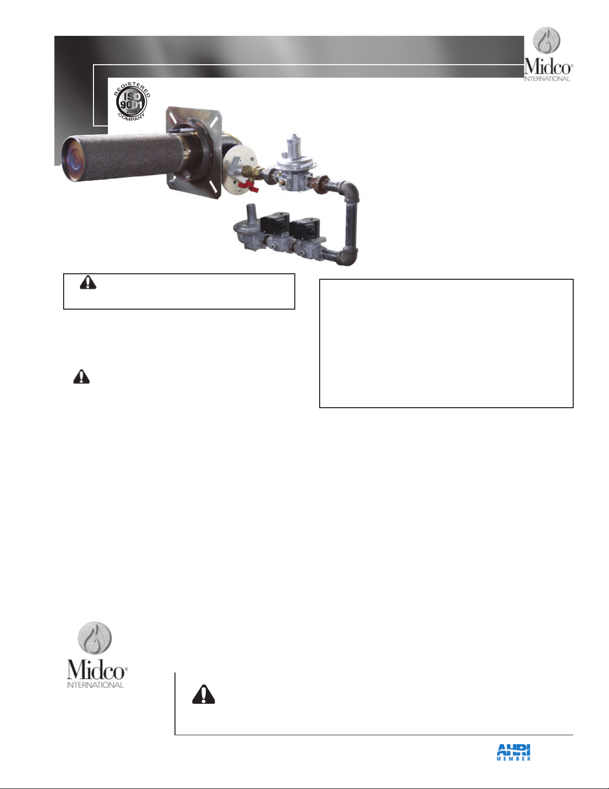
LNB 500 &
LNB 1000 Series
Low NOx Burners
Do not store or use gasoline or other fl ammable vapors and liquids in
the vicinity of this or any other appliance.
WHAT TO DO IF YOU SMELL GAS:
• Do not try to light any appliance.
• Do not touch any electrical switch; do not use any
phone in your building.
• Immediately phone your gas supplier from another
building. Follow the gas supplier’s instructions. If
you cannot reach your gas supplier call the fi re
department.
Installation and service must be performed by a qualifi ed installer,
service agency or the gas supplier.
BURNER MODEL: _____________________________________
BILL OF MATERIAL
NUMBER: _____________________________________________
SERIAL NUMBER #: ____________________________________
WIRING DIAGRAM: ___________________________________
FOR SERVICE CONTACT
Name: ________________________________________________
Address: ________________________________________________
________________________________________________
Phone: ________________________________________________
Date of Installation: _______________________________________
Midco® International Inc.
4140 West Victoria Street
Chicago, Illinois 60646
tel 866.705.0514
fax 866.580.8700
web www.midcointernational.com
e-mail sales@midcointernational.com
SAFETY INFORMATION TERMS: The following terms are used to identify hazards, safety precaution of special
notations and have standard meanings throughout this manual. They are printed in all capital letters using a bold
type face as shown below, and preceded by the exclamation mark symbol. When you see the safety alert symbol
and one of the safety information terms as shown below, be aware of the hazard potential.
DANGER: Identifi es the most serious hazards which will result in severe personal injury or death.
WARNING: Signifi es a hazard that could result in personal injury or death.
CAUTION: Identifi es unsafe practices which would result in minor personal injury or product and
property damage.
Quality Designed for Proven Performance
8471 91
Printed in USA
914
Page 2
Part 1 - Installation
Specifi cations
1
The LNB Series burners are adaptable to most makeup air units, ovens and after burners. The
Midco LNB Series LOW NOx Series gas burner was developed to meet the changing emission
requirements required today.
With Chamber
LNB 500 LNB 1000
MIN VELOCITY 1000FPM 1000 FPM
MAX VELOCITY 3500 FPM 3500 FPM
* MIN INSERTION DEPTH 4.5″ 4.5″
* MAX INSERTION DEPTH 25.0″ 25.0″
2
FIRING RATE (NATURAL)
LNB 500 LNB 1000
Push Through Pull Through Push Through Pull Through
MIN MBH 3 100 125 150 225
MAX MBH 3 500 500 1000 1000
GAS SUPPLY PRESSURE REQUIRED
NATURAL ................................................. Min 5.0″ W.C. Max 14.0″ W.C.
PROPANE ................................................. Contact factory
LNB 500 LNB 1000
MOTOR HP - AMPS 0.32 HP 0.40 HP
CFM BLOWER 229 SCFM 361 SCFM
ELECTRICAL SUPPLY..................................................... 120 VAC/ 60 Hz / 5 AMPS
Standard 120V optional
IGNITION CONTROL MODULE VOLTAGE .................... 24 VAC - Standard 120V optional
IGNITION TRANSFORMER ............................................ 120 VAC
FLAME SAFETY ....
Electronic fl ame Safety with Spark Ignited Pilot and 100% Sut-Off 4
Table 1. Burner Specifi cations
* Consult factory for optional insertion depth
1
Standard burners are shipped as NATURAL gas models. Consult Midco for propane applications.
2
All Ratings Based on 1000 BTU/Cu. Ft. NATURAL gas, at sea level.
3
1 MBH = 1,000 BTU/hr. , Min MBH depends on system velocity.
4
See Section VI Burner Ignition Sequence.
Part 1- Installation
2
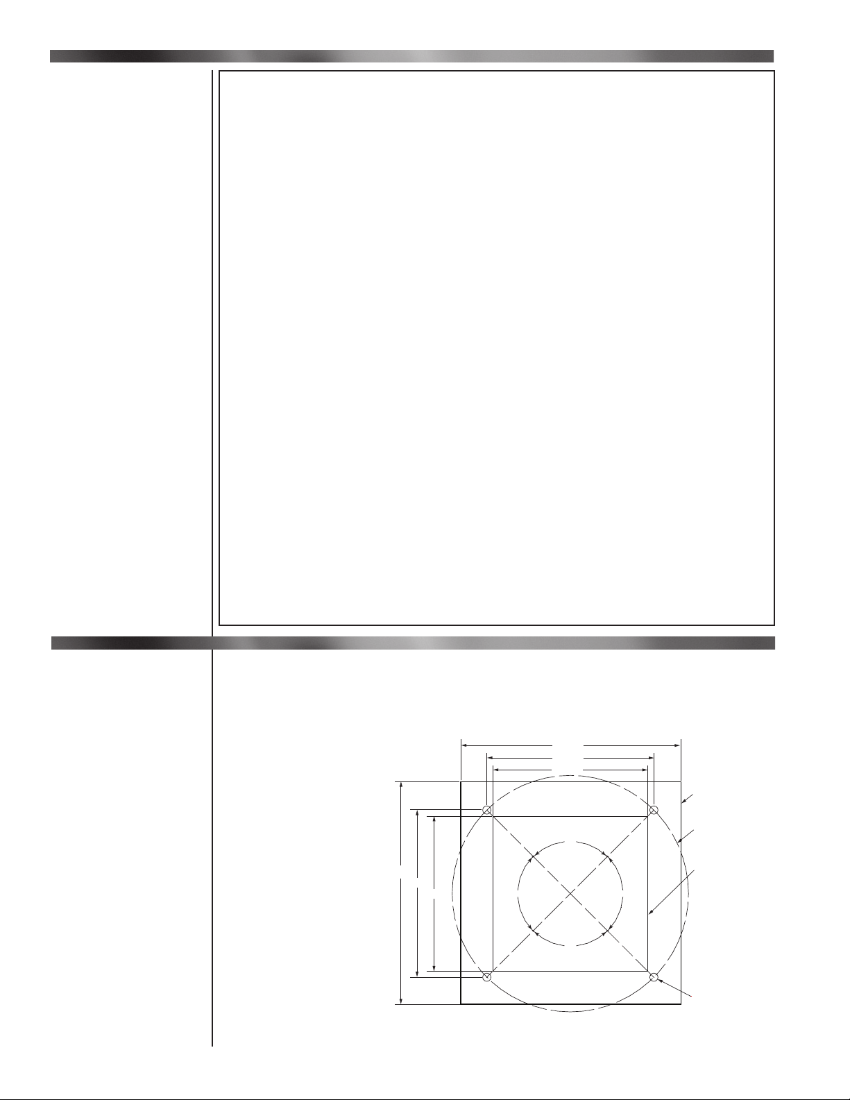
When installing the Midco LNB burner the following instructions must be followed.
The Midco LNB Burner must be installed per the equipment manufacturer’s instructions. If not available
take the following steps. To install the burner an opening on the side or top of the heater must be
provided. See Figure 1
be centrally located on a
pull through make up air
unit to promote even heat
for opening size and mounting information. The Midco LNB burner should
15.000
11.319
10.500
distribution. For a push
through unit the Midco
LNB burner should be
located in the center of
the blower discharge. For
other applications contact
our sales engineering
team. The opening of
the combustion chamber
15.000
11.319
10.500
90°
90°
90°
LNB
Mounting Flange
Ø16.000
10.50 x 10.50
Opening for
Combustion
Chamber
should be 90 degrees to
the blower. See Figure 2 for
proper chamber orientation.
90°
Clearance around heat
chamber must be a
minimum of 6″ on all sides.
Ø0.500 X 4
Figure 1 -
Midco International Inc.
LNB 1000 Mounting Flange
8471 91
Page 3
Part 1 - Installation
OFFSET INSIDE
HOT AIR
Ø10.000 Ø4.000
A A
1/2 A
Side Profile
LNB Combustion Chamber
Heater Box
Notes:
1. Above arrangement are for both push through and pull through units.
2. If the width or height of the combustion chamber is more than 28", a bottom profile plate may be required.
3. Any component, for example motor, blower, baffle, etc., should be 18" away from the chamber.
4. 3 o'clock arrangement is preferred.
5. For more information or special requirement please contact our Midco sales engineering team.
COLD AIR
24" or More
7" or More
Flame Exit
18"
or
More
18"
or
More
OFFSET OUTSIDE
Ø10.000 Ø4.000
1/2 B
LNB
COMBUSTION
CHAMBER
HEATER BOX
HOT AIR
COLD AIR
24" or More
B
7" or More
FLAME EXIT
18"
or
More
18"
or
More
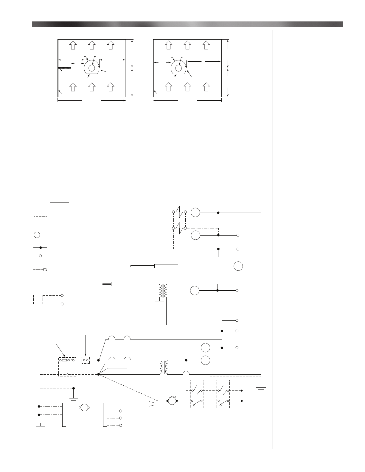
Figure 2 - LNB Burner Installation Guide - Typical Installation
__________________________________________
The Midco LNB wiring is included with the burner. Follow wiring diagram included with the burner for
proper wiring connections. When installing the Midco LNB burner all safety and operating controls
must be included and connected so if any safety fails the LNB burner will not operate. Do not bypass
any safety or operating control or equipment might be damaged.
LEGEND
SOLID WIRING AND COMPONENTS BY MIDCO
WIRING AND COMPONENTS BY OTHERS
SUPPLIED BY MIDCO INSTALLED BY OTHERS
MV
ENCIRCLED: SPARK IGNITION
CONTROLLER
5
SOLID ROUND: TERMINAL STRIP
OPEN ROUND: COMPONENT TERMINAL
P# TERMINAL ON RTC BOARD
P
WIRE NUT
2-10 VDC TEMPERATURE
CONTROLLER
+
-
(BY OTHERS)
P2
P4
SPARK ROD
SERIES CONNECT ALL SAFETY
AND / OR OPERATING CONTROLS IN
THE LINE (LINE
FUSE
VOLTAGE ONLY)
DISCONNECT
120/1/60
HOT
NEUTRAL
L1
L2
FLAME SENSE ROD
IGNITION
TRANSFORMER
BK
24V STEPDOWN
TRANSFORMER
BK
120V
W
RENDUNDANT
VALVE
MAIN
VALVE
BR
24V
4
3
BL
W
W
G
P7
(MAIN)
P8
G
S2
P10
(PILOT)
P12
P3
(120VAC)
P1
GND
MV1
S1
W
BK
2
BL
Y
8
BL
BL
7
BL/W BL/W
5
ORANGE
BL
BR BR
6
BK BK
L1
W
I Equipment
Preparation
Continued
II Wiring
GROUND
BK
3
BK
4
G/Y
G
G
M
TO BLOWER
MOTOR
W
R
P9
P11
P13
(V+)
(PWM)
(GND)
Y
BL
ALARM
24 V COIL
NO
NC
TIME DELAY
RELAY 60 SEC
(OPTIONAL)
Figure 3 - Wiring Diagram
__________________________________________
8471 91
Midco International Inc.
24 V COIL
NO
NC
RELAY
7
L1
3
Page 4

Part 1 - Installation
III Piping
The Midco LNB is provided with all required components to install the gas train assembly. Refer to
piping diagram Figure 4a and 4b for a typical installation. Required modifi cations can be made to
the piping layout if required. The Dungs Ratio Regulator Zero Governor valve position CAN NOT be
changed as this is critical in burner performance. There is an orifi ce located downstream from the
Dungs Ratio Regulator Zero Governor valve and must not be modifi ed. When complete with gas train
assembly installation turn on gas to the unit and check for any gas leaks. Repair any that were found
at this time. The minimum required gas pressure at the inlet of the valve train is 5″ WC and maximum
gas pressure not above 14″ WC. The outlet gas pressure should be set at 6″ when burner is at high fi re
full input. Turn off main manual gas valve before starting the unit. Consult the Midco technical support
team if there are any piping questions. See Burner Startup, section IV, for operating instructions.
EBM G170 BLOWER
8435-23
1"x 4" NIPPLE WITH
PRESSURE TAP
5243-46
BLOWER INLET
8416-18
KIT
1"x 3"
NIPPLE
8488-61
1" UNION
8493-06
1" MANUAL
BALL VALVE
8404-38
1"x 3"
NIPPLE
w/ ORIFICE
5246 64
1" RATIO REGULATOR
ZERO
GOVERNOR
8416-04
1"x 2"
NIPPLE
8488-52
PRE ASSEMBLED SECTION
1"x 2"
NIPPLE
8488-52
1"x 2"
NIPPLE
8488-52
1" ELBOW
8495-24
1"x 2"
NIPPLE
8488-52
1"x 6"
NIPPLE
8488-63
EBM RG175 BLOWER
8435-30
FUEL
GAS
BLOWER INLET KIT
8416-22
8493-06
1/8" PIPE
PLUG
8496-00
1" T HAND
BALL VALVE
8404-29
1" X 3/4" HEX BUSHING
8492-52
1" REGULATOR
RV61
8416-33
1" SOLENOID
VALVE 24 V
8402-36
MANOMETER
Figure 4a - Piping - LNB 1000 - Standard
3/4" RATIO
REGULATOR
ZERO
3/4" x 3" NIPPLE WITH
GAS ORIFICE
5246-85
MANUAL BALL VALVE
3/4" NPT
8404-37
3/4" NPT X 2"
LONG NIPPLE
8488-02
PRE ASSEMBLED SECTION
GOVERNOR
8416-211" UNION
3/4" X 3" NIPPLE
WITH GAS ORIFICE
5246-72
1" SOLENOID
VALVE 24 V
8402-36
MANOMETER
1" ELBOW
8495-24
1/8 PIPE PLUG
8496-00
3 WAY RDNDNT 3/4"
COMB VALVE 24 V
8419-43
Figure 4b - Piping - LNB 500 - Standard
4
Midco International Inc.
8471 91
Page 5

Part 1 - Installation & Service
LNB 1000 FIRING RATE vs PRESSURE DIFFERENCE ACROSS
TWO SOLENOID VALVES
1000
950
900
850
800
750
700
650
600
550
500
450
400
350
300
250
200
FIRING RATE, MMBTU/HR
150
100
50
0
0.00 0.10 2.202.102.001.901.801.701.601.501.301.201.101.000.900.800.700.600.500.400.300.20 1.40
PRESSURE DIFFERENCE ACROSS TWO SOLENOID VALVES, “W.C.
Chart 1 - Gas Pressure - LNB 1000
LNB 500 FIRING RATE vs PRESSURE DIFFERENCE
ACROSS 0.5” GAS ORIFICE
500
450
400
350
300
250
200
150
100
FIRING RATE, MMBTU/HR
0.00 2.202.001.801.601.201.000.800.600.400.20 1.40
PRESSURE DIFFERENCE ACROSS GAS ORIFICE, “ W.C.
III Piping
Continued
Chart 2 - Gas Pressure - LNB 500
__________________________________________
Power up unit and the starting sequence begins. The EBM blower motor is energized and will run up
to high blower speed for 20 seconds. After initial prepurge the EBM blower motor will modulate down
to low speed. Once EBM blower motor reaches low speed the main gas valve and ignition control
will be energized. If the burner lights and the temperature control is calling for heat the burner will be
modulated depending on the DC Volt signal being generated from temperature control.
__________________________________________
The Midco LNB burner comes with a limiting gas orifi ce which is required to maintain the Low NOx
readings and fi ring rate. The orifi ce is located between the dungs valve and EBM blower inlet. Do not
attempt to modify the location or orifi ce size. Attach a differential gas pressure manometer to check
gas fl ow. The locations for attaching the gas pressure manometer are located on the main gas valves.
See page 4. The taps that should be used is one on the upstream tap on fi rst main gas valve and the
other on the downstream BTM tap on the 2nd MGV for LNB 1000. Refer to piping diagram, Figure #
4a, for proper location. For LNB 500 attach a differential gas pressure manometer to check for gas
fl ow to outlet pressure tap on main gas valve, and the other on the 1/8″ tap on gas pipe downstream of
main gas valve. Remove the plug on both fi ttings. Attach a barb fi tting in order to hook up the required
8471 91
Midco International Inc.
IV Burner Startup
V Burner Setup
5
Page 6

Part 1 - Installation, Service & Maintenance
V Burner
Setup Continued
VI Burner
Ignition Sequence
tubing to the differential gas pressure manometer. Set temperature control below booth temperature
so burner will light and stay at low fi re (or remove DCV wiring from RTC board). Energize burner
power switch.
The burner blower will be energized and start sequence will begin. Once main fl ame established
the burner will start at low fi re. The gas pressure at the two gas pressure taps will be approximately.
1″ WC to .25″ WC. This is the minimum fi ring rate for the Midco LNB burner.
Adjusting low fi re: If the fl ame stays on and low fi re settings is too high, adjust low fi re on the Ratio
Regulator Zero Governor. The LNB burner is shipped with the adjustment screw located on the top of
the Ratio Regulator Zero Governor at 4-5 turns counterclockwise. To decrease low fi re turn the screw
counterclockwise. To increase the low fi re turn the screw clockwise. If the low fi re is adjusted properly
the fl ame will be mostly blue with a slight orange glow, visually inspect the fl ame through burner
peep sight. Check the differential gas pressure and fl ame signal and adjust the Ratio Regulator Zero
Governor valve as required.
Adjusting high fi re: Turn temperature control above set point to provide 10 DCV to RTC board to set
high fi re. Minimal adjustments can be made. Check inlet pressure to fi rst gas valve and it should be
5″ W.C. maximum. Adjust main gas pressure regulator if required. Flame signal should be steady and
above 2 DCuA. For gas pressure settings see Charts 1 & 2 on page 5.
__________________________________________
Burner Ignition Sequence:
1. Call for heat
a. LNB Burner blower will go to maximum speed
b. SCEBM-1 control LED will fl ash red
2. After 20 seconds delay
a. LNB burner will go to minimum speed
b. Ignition control will be energized
c. Ignition control will send 120V to the spark generator
d. SCEBM-1 control LED will remain solid red
e. Main gas valves will be energized
f. SCEBM-1 control LED will fl ash red or green, depending on DCV signal
VII Maintenance
If Burner ignites
A. Ignitor will be de-energized
B. Check DC micro amps signal at ignition control sense terminal which needs to be
above 1.5 micro amps
C. LNB Burner will modulate based on 2-10 VDC signal from the temperature control
D. SCEBM-1 control LED will remain solid green
If Burner does not ignite
A. Igniter will be de-energized
B. LNB burner blower will go to maximum speed
C. SCEBM-1 control LED will slowly fl ash red.
D. Red light on ignition control will be fl ashing.
E. Power will need to be de-energized and reset.
For additional trouble shooting information contact Midco International as shown on front page.
__________________________________________
The LNB burner will require maintenance every 12-18 months depending on usage. There are four
components that should be inspected. The EBM blower, pilot assembly, burner chamber and burner
head should be inspected. Turn off the main gas manual valve and main panel disconnect to insure
unit will not start. Remove the fl ame sensor wire, spark cable and wiring harness attached to the EMB
blower. To inspect the blower inlet loosen the union between the Dungs valve and blower. Loosen the
4 ½″ bolts attaching the burner to the heater. This will allow removal of the Midco LNB burner. Inspect
the heat chamber. To inspect the burner head you can look into the heat chamber and if any issue
contact Midco for replacement. The fl ame sensor and spark rod can be removed by loosening two
nuts holding the pilot assembly. To clean the sensor and spark rod if required you can use steel wool
6
Midco International Inc.
8471 91
Page 7

Part 1 - Maintenance
5246
or sand paper. If any crack on the porcelain then the sensor or igniter needs replacing. Reinstall the
LNB burner and make sure gas union and wiring were reinstalled. Open manual gas valve and
reenergize heater and cycle as shown in section IV - Burner Startup.
7
1
8
2
9
10
Item Part # Description Qty
1 Hardware #8-32 X 5/16 Socket Head Cap
2 5246-45 Ignition Assembly Weldment Spk 1
3 8432-21 O-Ring 1/2" X 11/16" X 3/32" 1
4 5246-22 Ignition & Flame Assembly Plate 1
5 5246-48 Igniter Flange Gasket Spk 1
6 5246-17 Flame Rod LNB Assembly 1
7 Hardware 1/4-20 Hex Nut 2
8 Hardware 1/4" Split Lock Washer 2
9 Hardware 1/4" Star Lock Washer 2
10 8432-20 O-Ring 5/32" X 11/32" X 3/32" 1
11 8432-22 O-Ring 7/16" X 5/8" X 3/32" 1
12 5246-43 Spark Rod Assembly LNB 1
3
11
4
12
Screw
5
6
NOTE: Flame rod
tip angled to
the side
FROM TIP TO TIP
5/32" +/- 0.01 GAP
FRONT VIEW
-42R
1-1/2"
1-15/32"
SIDE VIEW
4
VII Maintenance
Continued
(Note: Kit # 5246-42R includes Items #s - 1,2,3,5 and 6)
__________________________________________
The Midco LNB burner uses a direct spark pilot. The LNB direct spark pilot is factory set. The spark
gap should be set at 5/32″ from center ground rod. Inspect porcelain on the fl ame rod and spark
rod. Any signs of a crack the rods should be replaced. For proper parts selection contact Midco
International as shown on the front page. When re-installing a direct spark pilot the fl ame rod should
be installed on the right side of the unit.
__________________________________________
8471 91
Figure 5 - Direct Spark Pilot Assembly
Midco International Inc.
VIII Pilot
Assembly
7
Page 8

8
tel: 866.705.0514 - fax: 866.580.8700 - web: www.midcointernational.com - e-mail: sales@midcointernational.com
Midco® International Inc. - 4140 West Victoria Street - Chicago, Illinois 60646
914
8471 91
Printed in USA
 Loading...