

Page 1
In the United States,installation must conform with local
codes or, in the absence of local codes, with Installation
of Domestic Gas Conversion Burners, ANSI Z21.8alatest edition and National Fuel Gas Code, ANSI
Z223.1-latest edition(s) available from American
National Standard Institute. Further reference should be
made to the recommendation of your fuel supplier.
Note: Any additions, changes or conversions required in
order for the gas utilization equipment to satisfactorily
meet the application needs must be made by a MIDCO
distributor (or other qualified agency) using factory
specified and approved parts.
In Canada, installation must conform with local codes or,in
the absence of local codes, with Installation Codes
for Gas Burning Appliances and Equipment, CGA
Standard CAN/CGA 1-B149.1 or 2. When the
conversion burner is used on Forced Air Central
Furnace, the two yellow and black warning labels in the
literature envelope shall be attached in accordance with
Installation Code, CGA Standard CAN/CGA 1-B149,
Clause 5.4.4.4. Further reference should be made to the
recommendation of your fuel supplier.
INSTALLER: Inform and demonstrate to the user the
correct operation and maintenance of this gas utilization equipment. Inform the userof the hazards of storing flammable liquids and vapors in the vicinity of this
gas utilization equipment and remove such hazards.
Affix this manual adjacent to the conversion burner.
CODE COMPLIANCE IS THE SOLE RESPONSIBILITY
OF THE INSTALLER.
WARNING: If the information in
these instructions is not followed exactly, a fire or explosion
may result, causing property damage, personal injury or death.
Do not store or use gasoline or other
flammable vapors and liquids in the
vicinity of this or any other appliance.
Installation and service must be performed by a qualified installer, service
agency or the gas supplier.
WHAT TO DO IF YOU SMELL GAS
• Do not try to light any appliance.
• Do not touch any electrical
switch; do not use any phone in
your building.
• Immediately call your gas
supplier from a neighbor's
phone. Follow the gas suppliers'
instructions.
• If you cannot reach your gas
supplier, call the fire department.
USER: Retain this manual for future reference. If other than routine service or maintenance as
described in this manual is required, contact a qualified service agency. DO NOT ATTEMPT REPAIRS.
An inadvertent service error could result in a dangerous condition.
SAFETY INFORMATION TERMS: The following terms are used to identify hazards, safety precautions or special nota-
tions and have standard meanings throughout this manual. When you see the safety alert symbol and one of the safety
information terms as shown below, be aware of the hazard potential.
DANGER: Identifies the most serious hazards which will result in severe personal injury or death.
WARNING: Signifies a hazard that could result in personal injury or death.
CAUTION: Identifies unsafe practices which would result in minor personal injury or product and property damage.
Installation and Service Instructions
Midco International Inc.
4140 West Victoria Street Chicago, Illinois 60646
tel 773.604.8700 fax 773.604.4070
web www.midco-intl.com e-mail sales@midco-intl.com
1207
8470 72
Printed in USA
Economite DS45B
Gas Conversion Burner
Quality Designed for Proven Performance
The Economite Model DS45B direct spark ignition conversion burner is adaptable to most gas utilization equipment, including
gravity and forced circulation furnaces and boilers, and is particularly recommended for horizontal and downdraft gas utilization
equipment since it needs no draft to maintain a pilot. Power burner design makes it perfectly suited for oil burner replacement.
Page 2

Part 1 Installation
Specifications
Part 1
Installation
Derate burner for altitudes over 2,000 feet by 4% for each 1,000 feet of additional elevation.
IMPORTANT: The ECONOMITE DS45B is not intended for outdoor installation and must be
protected from excessive moisture. Provide adequate clearance for service and proper
operation.
If the former automatic oil burner gave trouble-free operation, it is probable that the gas
utilization equipment area has sufficient infiltration of air for combustion and dilution of flue
gases. Nevertheless, the area must be checked:
Open basement or utility areas of normal construction, without storm windows or tight
doors, will generally allow sufficient air infiltration. However, if the gas utilization equipment
is located in a tight or separate room, ventilation to an open area as described above will be
required. Install two permanently open grills, each sized on the basis of one square inch
free area per 1,000 BTU (but not less than 100 square inches) of the total input rating of all
gas utilization equipment in the combined space. One grille should be located within 12
inches of the ceiling, the other within 12 inches of the floor.
If the gas utilization equipment is located in an area of unusually tight construction, or if
an exhaust fan, kitchen ventilation system, clothes dryer and/or fireplace is installed in the
building, provision must be made for an outside air supply near the gas utilization equipment
area. Install permanently open grills sized at not less than one square inch free area per
4,000 BTU of burner input. When ventilating through horizontal ducts, grills should be
sized at not less than one square inch free area per 2,000 BTU of burner input. In any
case, the minimum dimension of rectangular air ducts shall not be less than 3 inches.
In Canada, for detailed ventilation requirements, refer to standard CAN 1-B149.1 or .2
and/or local codes.
______________________________________________________
Clean the gas utilization equipment, combustion chamber, heat exchanger interior and
flue connections. Remove all adhering tars, scale, dirt and soot. Inspect for actual leaks
and/or potential leaks.
Cement all joints, including those in the gas utilization equipment base and around door
frames, to prevent leakage into or out of the combustion chamber.
The access or firing door should open easily to relieve pressure. If positive latches exist,
they should be modified to permit easy opening; a spring loaded door holder is
recommended.
On all boilers, make certain the pressure relief safety valve is in good operating condition.
______________________________________________________
A combustion chamber liner is normally required to protect non-heat transfer surfaces and to
provide a radiant bed for rapid heat transfer to the primary surfaces of the heat exchanger.
In most cases an existing oil burner combustion chamber liner can be used, if in good
condition.
2
SPECIFICATIONS NATURAL or PROPANE Gas
AIR DELIVERY (Approximate Air Delivery at Zero Draft Draft)........ 85 SCFM*
MAXIMUM FIRING RATE**..............................................................400 MBH***
MINIMUM FIRING RATE**...............................................................200 MBH***
TUBE DIAMETER................................................................................4 inches
TUBE LENGTH....................................................................................9 inches
MINIMUM COMBUSTION CHAMBER SIZE
400 MBH................................................10" W X 161/2" L or 15" dia.
300 MBH.......................................................9" W x 14" L or 13" dia.
200 MBH.......................................................7" W x 11" L or 10" dia.
GAS PRESSURE REQUIRED
NATURAL................................................................5.0" to 14.0" W.C.
PROPANE.............................................................11.0" to 14.0" W.C.
STANDARD VOLTAGE......................................120 Volts..................60 Cycle
FLAME SAFETY..........Direct Spark Ignition of Main Flame, Electronic Safety
MAIN AUTOMATIC VALVE...........................................3 Function Redundant
* SCFM = Standard Cubic Feet/Minute
** Ratings Based on 1000 BTU/cu. ft. NATURAL, 2500 BTU/cu. ft. PROPANE at
Sea Level
*** 1 MBH = 1,000 BTU/Hr.One gallon fuel oil =140MBH.
II Preparation of the Gas
Utilization Equipment
I Ventilation
III Combustion Chamber
Page 3

Part 1 Installation
Part 1
Installation
Continued
IV Chimney, Vent
Connector*, and
Draft Control
*Formerly referred
to as Flue Pipe
3
In the case of wet base boilers, where the entire firing chamber is comprised of heat
exchange surfaces and no chamber liner was provided for oil firing, a liner is usually not
required for the ECONOMITE. However, a liner or target wall may be necessary if the firing
chamber is unusually short, in order to avoid flame contact on the heat exchanger walls or
flueways.
If a built up chamber liner is required, use 2300
o
F minimum insulating material.
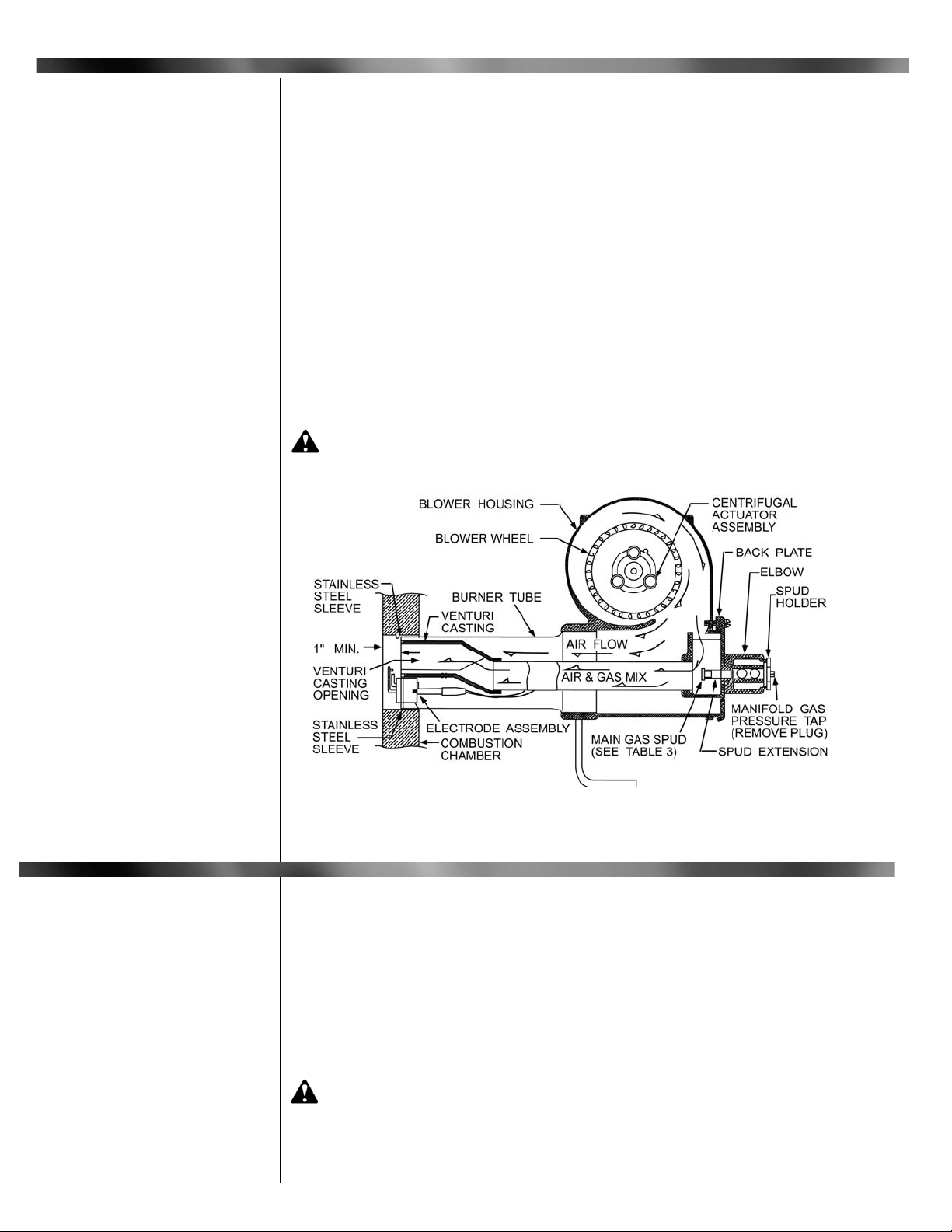
The burner tube, or the stainless steel sleeve that is included with the burner, must be
sealed air tight into the combustion chamber liner opening with refractory material as shown
by Figures 1 and 2. The sleeve is preferred as it is designed to properly locate the end of
the tube relative to the inside wall of the combustion chamber, and to permit burner removal
without breaking the seal.
NOTE: In no case should the burner tube be allowed to extend into the chamber proper; it
must be set flush to 1" short of the inside surface, because high combustion chamber
temperatures will cause premature electrode deterioration.
Special heat resistant alloy extension tubes and instructions are available for those
applications where the burner tube is too short to reach the combustion chamber (such as
old-fashioned gravity warm air furnace installations).
WARNING: Burner cabinet must be mounted in orientation shown in Figures
1 and 2. Any other mountings may cause a dangerous condition, and will void burner
warranty and agency approvals. Non-standard arrangements may be available for
some models; consult factory for details if required.
Before permanently setting the burner in place, check that the venturi casting openings
are free of foreign materials and the electrodes have not been damaged or displaced. See
Figure 6.
______________________________________________________
The chimney shall be inspected
for unsafe conditions such as
deteriorated masonry and
excessive soot or other blockage
or potential blockage.
The Vent Connector shall be
connected to a chimney already
venting solid fuel burning
equipment, an incinerator or an
open fireplace.
The Vent Connector shall be
made of non-combustible,
corrosion resistant material
capable of withstanding the vent
gas temperature produced by the
gas utilization equipment and of
sufficient thickness to withstand
physical damage.
The Vent Connector shall be as
short as possible. The entire
length shall be readily accessible
for inspection, cleaning and
replacement.
III Combustion Chamber
Continued
Figure 1: Dry Base Boiler with Combustion
Chamber Liner (Warm Air Furnace
Construction is Similar)
Figure 2: Wet Base Boiler with Unlined
Combustion Chamber
Figure 3: Draft Hood Positions
Page 4
V Electrical
The length of horizontal uninsulated Vent Connector between chimney and a single gas
utilization equipment shall not exceed 75% of the height of the chimney above the
connector, or 100% if the Vent Connector is insulated.
The Vent Connector shall be installed so as to avoid turns or other construction features
which create excessive resistance to flow of vent gas. It shall be installed without any dips
or sags and shall slope upward at least 1/4" per foot.
A manually operated damper shall not be placed in the Vent Connector or chimney of
any gas utilization equipment.
The Vent Connector shall be firmly attached to draft hood outlets and flue collars. Joints
between sections of connector piping shall be fastened by sheet-metal screws or other
approved means. The Vent Connector shall be supported for the design and weight of the
material employed to maintain clearance and prevent physical damage and separation of
joints.
A draft hood or a barometric draft regulator shall be installed in the same room or
enclosure as the equipment in such a manner as to prevent any difference in the pressure
between the hood or regulator and the combustion air
supply. In no case shall the relief opening of the draft hood
or barometric draft regulator be located at a point lower than
the top of the highest flue passage in the equipment.
Gas utilization equipment requiring controlled draft may
be equipped with a listed double acting barometric draft
regulator, installed and adjusted in accordance with the
manufacturer’s instructions, if approved by local codes.
A device which will automatically shut off gas to the
burner in the event of sustained backdraft is required. It
shall be of the listed manual reset type and installed and
adjusted by a qualified service technician in accordance
with the manufacturer’s instructions.
______________________________________________________
Installation wiring and grounding of the burner must conform to local codes, or, in their
absence in the United States to National Electric Code, ANSI/NFPA No. 70- latest edition;
in Canada, to Canadian Electrical Code Part 1, CSA Standard C22.1.
Use copper wire not less than 14 gage for line voltage wiring. Be sure to hook up to
permanently live circuit. Provide a fused on-off disconnect switch carrying a minimum 3
amp fuse.
4
Part 1 Installation
Part 1
Installation
Continued
IV Chimney, Vent
Connector*, and
Draft Control
Continued
250 MBH
320 MBH
400 MBH
7”
8”
9”
Maximum
Input
Flue Pipe
Diameter
Table 1: Recommended
Vent Connector Sizes
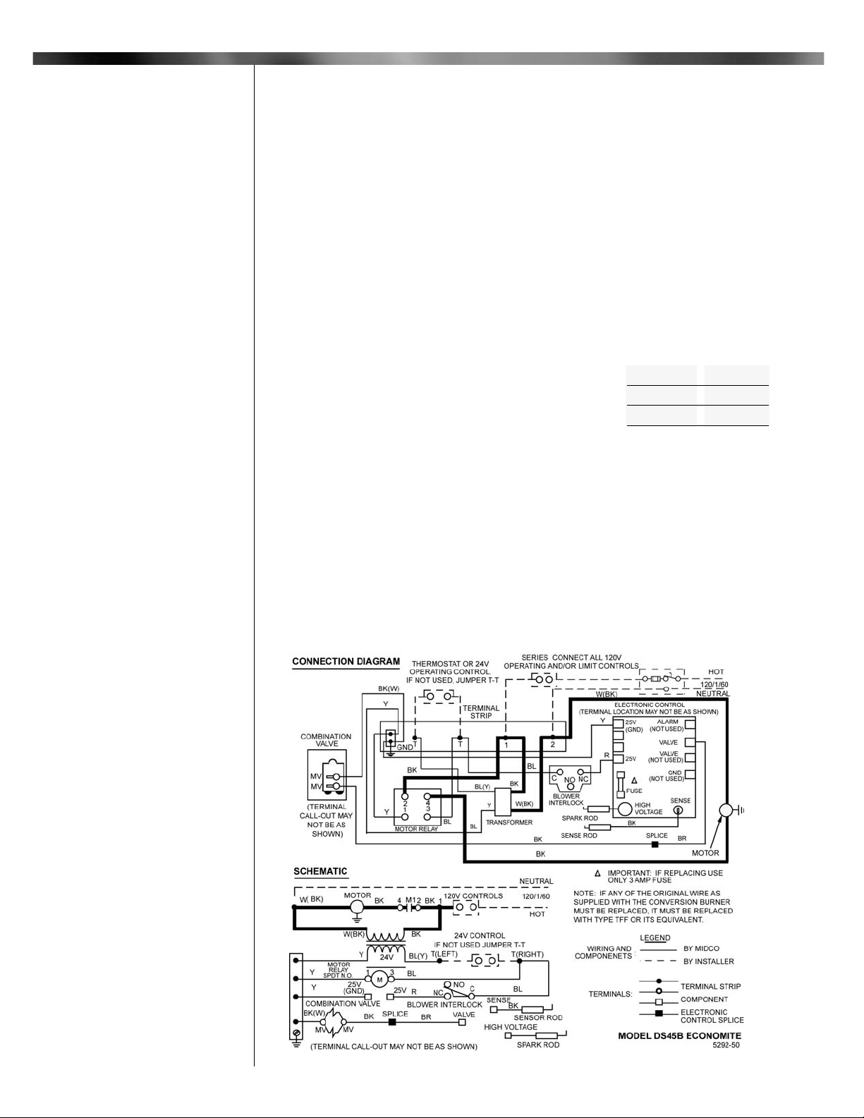
Figure 4: Wiring Diagram
Page 5

Part 1
Installation
Continued
The frame of the burner should be well grounded. Normally the piping and/or electric
conduit will provide sufficient grounding. However, a terminal is provided on the terminal
strip for positive grounding where insulated pipe couplings are used or where any doubt
exists regarding grounding sufficiency.
Confirm that the polarity is correct -- hot wire to strip terminal 1, neutral 2 -- and that the
neutral line is not subject to induced low voltage (check 2 to earth ground) from other
equipment, as that can cause the electronic flame safeguard to malfunction.
Each installation must include suitable limit control(s). Existing oil burner combination
operating and limit controls are normally NOT SUITABLE for gas burner use.
Set the thermostat heat anticipator for the total current draw handled by the thermostat.
The current draw of the Economite 24V operating circuit is 0.7 amps.
CAUTION: Label all wires prior to disconnection when servicing controls.
Wiring errors can cause improper and dangerous operation. Verify proper operation
after servicing.
CAUTION: Do not add any power consuming devices in the low voltage circuit as it could overload the transformer. Do no use the Motor Relay to operate any
external devices as the extra load could damage the relay contacts.
NOTE: If any of the original wiring as supplied with the conversion burner must be
replaced, it must be replaced with type TFF wire or its equivalent.
______________________________________________________
CAUTION: The available gas
pressure should be within the limits
shown in SPECIFICATIONS section.
Excessive pressure will damage
Combination Valve and Regulator. If
the supply pressure exceeds the
14.0" W.C. maximum, a suitable
intermediate main regulator must be
installed ahead of the Main Manual
Shut-Off Valve shown in Figure 5.
The burner gas supply piping should
branch off from the main line as close
to the gas meter as possible. Do not
connect to the bottom of a horizontal
section. Use new black pipe and
malleable fittings free of cutting and
threading burrs or defects.
Provide a sediment trap, union and
1/8" pressure tap in piping close to
burner as shown in Figure 5.
Use pipe joint compound resistant to
Liquid Petroleum Gases.
Piping must comply with local codes.
To obtain the maximum firing rate of
400 MBH, the NATURAL gas supply
piping must be sized to provide a minimum of 5.0" W.C. pressure (11.0" W.C.
PROPANE) to the inlet of the combination valve when the burner and all
other gas utilization equipment are on.
CAUTION: Because it is
difficult to accurately control
pressure during supply pipe leak test, it is recommended that the Combination Valve
be disconnected. Exposing the Combination Valve to a pressure over 1/2 PSIG will
damage the valve and void its warranty.
DANGER: Explosion.hazard. Do not use oxygen for pressure testing.
An explosion could occur during initial start-up.
If the burner piping must be rearranged because of space limitations, be sure to carry out
the general arrangement shown in Figure 5. Install the combination valve in any position
except up-side down.
When the burner is installed in jacketed equipment, it is recommended that the
Combination Valve be left adjacent to the burner within the vestibule and the Main Manual
Shut-Off Valve be installed outside.
______________________________________________________
5
Part 1 Installation
VI Piping
V Electrical
Continued
Pipe
Size
3/4
1
1 1/4
1 1/2
400
400
250
250
400
400
200
200
350
400
400
250
300
400
Type of
Gas
Propane
Natural
Propane
Natural
Propane
Natural
Capacity - MBH
Length of Pipe
Capacities shown are for a total pressure drop of
0.3” W.C. For 0.5” W.C. pressure drop, multiply
capacity shown by 1.3. For higher permissible
pressure drops, consult your fuel supplier.
15 30
45
90
Table 2: Supply Pipe Capacities in MBH
Figure 5: Piping Connections
Page 6

Standard burners are approved for use with NATURAL or PROPANE gas only, and should
be used only with the gas specified on the rating plate.
A standard Model DS45B ECONOMITE burner is shipped ready for NATURAL gas. As
shipped, it is field convertible to PROPANE gas. See Below.
A standard NATURAL gas Model DS45B burner is shipped with a .343 diameter orifice
installed for an input capacity range of approximately 225 to 320 MBH. A second orifice with
a .390 diameter orifice for an input capacity range of approximately 300 to 400 MBH is
included in NATURAL SPUD KIT attached to burner (see Table 3).
If a standard NATURAL gas Model DS45 is to be used with PROPANE gas, a conversion
kit which contains 5 main orifice spuds, a PROPANE regulator head, a PROPANE label and
instructions. Affix the PROPANE label over the NAT designation on the rating plate.
If the required firing rate does not fall within the range of the installed spud, or if converting to PROPANE gas, select the correct input capacity range from Table 3 and install the
spud with the correct orifice size (stamped with inch diameter) from the spud kit bag. If the
required firing rate is at the minimum of a capacity range, select the next lower range spud.
TO CHANGE MAIN SPUD: Turn Manual Gas Cock Knob on Combination Valve to OFF.
Remove the Spud Holder. See Table 3 and Figure 5 or 8.
The combination valve main gas pressure regulator is set to provide 2.0" W.C. NATURAL
(8.0" W.C. PROPANE) manifold gas pressure for low to minimum capacity spud input. The
burner is shipped with the primary air controlling shutter set wide open to provide a lean
gas/air mixture during the initial start-up. Do not change the combination gas valve pressure
regulator setting at this time.
CAUTION: The approximate air and gas settings described above are for
initial start up only. Final settings must be made in accordance with Section VIII .
Instructions for adjustment of the manifold gas pressure are detailed in Section XI .
______________________________________________________
WARNING: Ignition is automatic. Make spark observations into combustion
chamber only with Main Manual Shut-Off Valve closed. Confirm that gas utilization
equipment does not contain any accumulated gases. Purge as described in Step 3
below.
1. Check the burner piping and valves for gas leaks by applying a weak liquid soap
solution to unions and joints with the gas supply on. Leakage will be indicated by the
appearance of soap bubbles. Locate and correct all gas leaks before proceeding.
WARNING: DO NOT USE OPEN FLAME.
2. Purging the air from the gas supply line at this step will expedite the first light-off.
IMPORTANT: Purge outside the building.
Do not purge into the gas utilization equipment.
3. To purge the gas utilization equipment and chimney of any accumulated gases, turn
Manual Gas Cock Knob on Combination Valve to OFF, turn burner power on, and set
operating control to ON or thermostat to call for heat. Let the blower run long enough to
accomplish four air changes, but not less than five minutes.
VII Initial Start Up/
Adjustment
6
Part 1 Installation
Part 1
Installation
Continued
VII Main Gas Spud
Table 3: Spud Capacity and Preliminary Gas Settings
Page 7

4. IMPORTANT: Make sure that the capacity range of the installed spud and the
preliminary primary air shutter setting are suitable for capacity rating of the gas utilization
equipment. Refer to Section VII and Table 3.
5. RESET the Electronic Control by setting the operating control to OFF or the thermostat
below room temperature for at least 30 seconds. See Section XII .
6. Confirm that Main Manual Shut-Off Valve is open. Turn Manual Gas Cock Knob on
Combination Valve to ON.
7. Turn operating control to ON or set thermostat above room temperature. Main flame
should come on when the motor reaches operating speed. Whenever the burner fails to
light during the 6-second ignition trial, or if the flame is lost during the burner run and is
not re-established within 6 seconds, the Electronic Control will shut off the Combination
Valve and LOCK OUT To RESET the Electronic Control for restart, de-energize the
Electronic Control by setting the operating control to OFF or thermostat below room
temperature for at least 30 seconds. If burner still fails to light, turn it off and repeat from
step 5 above. Then, if necessary, refer to the TROUBLE CHART to isolate the problem.
WARNING: Repeated unsuccessful attempts to light will result in accumulated
gases in gas utilization equipment and chimney. To prevent these gases from
reaching an explosive level, periodically purge the gas utilization equipment
and chimney as described in step 3 above.
8. To make a preliminary setting of the burner input, determine the manifold gas pressure
required from Table 3 and adjust the combination valve main gas pressure regulator
accordingly. See Section XI .
9. To determine the firing rate for NATURAL gas, accurately time test dial for the number of
seconds for one revolution and use the following formula. All other gas utilization
equipment must be off.
Then Divide by 1,000 for MBH value.
For PROPANE gas, consult your supplier for method of determining firing rate
10. Readjust the primary air shutter to provide a quiet, soft blue flame with well defined
orange and yellow tips for NATURAL gas or with well defined yellow tips for PROPANE
gas.
11. Check the operation of the burner; start and stop it several times with the thermostat or
operating control.
12. With the burner running, check the operation of all limit and associated controls.
13. PERFORM THE FOLLOWING FINAL ADJUSTMENTS for combustion and flue gas
temperature. Take the flue gas samples and temperature immediately ahead of the
draft control.
A. The flue gas temperature should be above 325°F but not exceeding 550°F.
Excessive flue gas temperatures will result in low efficiencies. Low flue gas
temperature may cause excessive condensation. Reset gas input if necessary to
adjust stack temperature.
B. Make the final setting of the primary air shutter by checking the flue gases with an
ORSAT or similar combustion testing instrument. The carbon monoxide content
should conform to local codes, or, in their absence to the level specified in the
United States or Canadian Standard referenced on the front cover of this manual;
and the carbon dioxide content should be approximately 9.5% for NATURAL and
12.1% for PROPANE, or within the limits prescribed by local codes.
14. Check the draft control to make sure there is no spillage of flue products into the room.
15. FILL OUT THE INSTALLATION ADJUSTMENT DATA TAG and affix to the burner or
gas utilization equipment.
NOTE: For subsequent normal starting and shut off procedure, refer to CONSUMER
INSTRUCTIONS or to the instruction plate mounted on the burner.
______________________________________________________
7
Part 1 Installation
Part 1
Installation
Continued
VIII Initial Start Up/
Adjustment
3600 x test dial size x BTU value
No. of seconds for one rev. test dial.
= BTU/Hr.
3600 x 1 x 1000
20
= 180,000 BTU/Hr. = 180 MBHExample:
Page 8
DANGER: Be sure that the Main Manual Shut-off Valve, Combination Valve
and Burner Power Switch are turned OFF before removing any parts for service.
The venturi casting and electrodes are part of the drawer assembly which can be
removed as a unit. Remove the two back plate screws; then disconnect the elbow and pull
out the drawer assembly.
When servicing, clean venturi casting openings and electrodes. Inspect the wires and
porcelain insulators carefully for hairline cracks which might provide an electrical leak path
that could short out the ignition spark or flame signal.
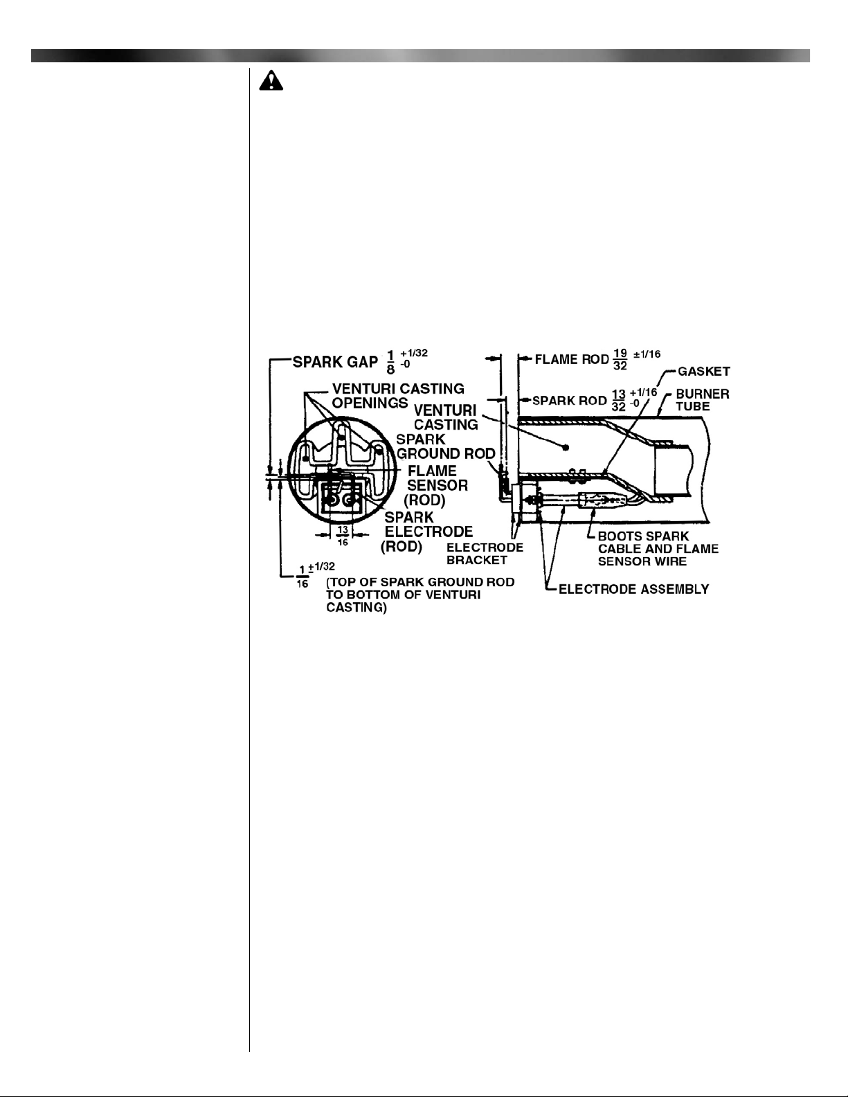
Examine the electrodes for any serious corrosion or loss of metal at the tip. The
electrode assembly is not adjustable. If the electrodes have been bent out of position, or the
spark gap is too wide (see Figure 6), the assembly is defective and must be replaced. Make
sure that the wires go to the correct electrodes and that the rubber boots are in place.
Make sure that the burner tube is properly positioned in the combustion chamber entry. It
must be set 1" short of the inside face of the combustion chamber as shown in Figures 1,2
or 8.
______________________________________________________
NOTE: BEFORE SERVICING, mark with a scribe line or measure opening of primary air
controlling shutter, so that it can be reset to its original position following servicing.
Cleaning of the blower wheel is usually the only service required. Need for cleaning is
indicated if the air cage assembly shows an accumulation of dust and lint, or if the character
of the flame indicates a deficiency of air. Motor cooling air vents should also be cleaned at
this time.
The blower side plate, motor and wheel are removed as an assembly. Disconnect the
motor wires from terminal 2 on the burner terminal strip and 4 on the motor relay.
Disconnect the motor conduit from the control box and remove the side plate screws.
The blower wheel is equipped with a spring loaded centrifugal actuator to operate an
electrical interlock switch so as to prevent the burner from firing if the blower wheel is not
running at its operating speed. When the motor is off, the actuator spring forces the disk
against the switch plunger to push it past its operating point. When running, the actuator
pulls the disk clear of the plunger.
To make a specific test of the interlock circuit:
1. Turn burner power OFF.
2. Turn Manual Gas Cock Knob on Combination Valve to OFF.
3. Disconnect the motor wire from terminal 4 of the motor relay to keep the motor off.
4. Turn burner power ON and set the operating control to ON or thermostat to call for
heat. Check for 24V between the Electronic Control 25V and 25V GND terminals.
8
Part 2 Service
Figure 6: Venturi Casting and Electrode Assembly
X Venturi Casting
and Electrodes
Part 2
Service
IX Blower Assembly
Page 9

A. No voltage: Interlock circuit OK.
B. Voltage present: check that switch bracket is screwed down tight (see Figure 7).
If so, without disconnecting switch wires, remove switch bracket and manually
depress switch plunger. If voltage is still present, or if the plunger has to be
depressed to where dimension "A" of Figure 7 is less than 9/32" when switch
clicks over, replace the switch.
5. If the switch tests OK, check dimension "A" of Figure 8 as follows:
Switch plunger free...................9/32 to 11/32"
Disk free....................................7/32 to 1/4"
Disk held all the way in.............15/32" min.
6. If plunger dimension is wrong, replace switch. If disk dimension is wrong, check that
the actuator operates freely with a minimum movement of 1/4" from the free position.
If movement is OK, reposition blower wheel on motor shaft. If not, replace wheel.
______________________________________________________
The 24 volt combination valve serves three functions:
1) Manual Gas Shut-off, 2) Manifold gas pressure regulation, 3) Automatic electric redundant (double seated) gas valve.
For manual control the Manual Gas Cock Knob is turned full ON or full OFF. The dial has
to be depressed to be turned in one direction, but it depends on the make of the valve
whether it is to the ON or OFF position.
The main gas pressure regulator, which has an outlet pressure setting range of
approximately 2.0" to 4.0" W.C., is factory set for a manifold gas pressure of 3.5" W.C. for
NATURAL. If pressure adjustment is required for setting capacity, remove regulator cap for
access to slotted adjustment screw. Turning of adjustment screw counter-clockwise reduces
pressure; clockwise increases pressure. Do not adjust past the point where no change in
pressure is noted.
NOTE: Pressure setting must be made with burner running and main gas ON.
CAUTION: When adjusting the regulator, if gas supply pressure is below its
specified range, an overfire condition could result as pressure returns to normal,
particularly if the regulator adjustment screw is bottomed out.
ALWAYS confirm that at least the minimum rated gas pressure is being supplied to the
burner during regulator adjustments, and NEVER bottom out regulator screw.
To set to low outlet pressure for initial startup, turn the adjusting screw counter-clockwise
2.5 turns to raise it to about 1/4" below the top.
The tap for manifold gas pressure measurement is located in the burner spud holder (see
Figure 5 or 8). Remove plug for access.
If the gas pressure regulator fails to maintain a constant manifold gas pressure within +
0.1" W.C., and it is confirmed that the inlet gas pressure to the combination valve is 14.0"
W.C. maximum during standby, and 5.0" W.C. minimum for NATURAL gas (11.0" W.C. for
PROPANE gas), with the main flame on, the regulator portion of the valve is defective and
the entire valve must be replaced.
9
Part 2 Service
Part 2
Service
Continued
Figure 7: Motor, Blower Wheel and Interlock Assembly
XI Combination Gas Valve
IX Blower Assembly
Continued
Page 10
If, on a call for heat, flame ignition does not occur, refer to the trouble chart for further
information.
If leakage through the valve occurs, as evidenced by the presence of flame on standby,
the entire valve must be replaced.
If the combination valve has been moved or replaced, soap bubble test for leaks with the
burner running.
______________________________________________________
The Electronic Control is a 24 volt AC, solid state electronic device that automatically ignites
and monitors the flame. It has an integral high voltage transformer and, upon a call for heat,
applies high voltage to the spark electrode and 24V to the combination valve. When the
flame is proven, the spark is terminated and the burner run continues.
If the flame is not proven within 6 seconds, or if the proof of flame is lost during the
burner run and not re-established within 6 seconds, the Control will shut off the combination
valve and lock out. To reset the Electronic Control for restart, de-energize the Electronic
Control by setting the operating control to OFF or thermostat below room temperature for at
least 30 seconds.
If the Electronic Control is changed, the replacement must be identical as to the make
and model number, or must be an authorized substitute.
WARNING: Explosion hazard.
Do not use this device if it gets wet. It can malfunction and cause serious
injury or death. Replace any device that has been wet.
______________________________________________________
Keep the area around the burner clear and free of combustible materials, gasoline or
other flammable liquids or vapors. Do not obstruct burner air openings or ventilation grills
for combustion air.
The motor features permanently lubricated ball bearings and requires no routine oiling
maintenance.
IMPORTANT: Check the burner flame periodically. A proper NATURAL gas flame will appear
blue at the burner face with orange and yellow tips. A proper PROPANE gas flame will
appear blue at the burner face with yellow tips. If the flame is too rich, it will appear billowy
and yellow with hazy tips. If too lean, it will appear short and all blue. If the flame does not
appear proper, CONTACT A QUALIFIED SERVICE TECHNICIAN FOR CLEANING
AND/OR READJUSTMENT.
WARNING: If any flame is observed when the burner is on standby, or if the
ignition spark or valve operator is heard to come on before the motor reaches
operating speed, immediately turn off the manual gas control and burner power. A
dangerous condition has developed and must be corrected. CONTACT A QUALIFIED
SERVICE TECHNICIAN FOR CLEANING, READJUSTMENT OR REPAIR.
Part 2 Service
Part 2
Service
Continued
XI Combination Gas Valve
Continued
Consumer Instruction
Figure 8: General Assembly
10
Consumer Instruction
Maintenance
XI Electronic
Control System
Page 11
Maintenance Continued
LIGHTING INSTRUCTIONS:
1. SET OPERATING CONTROL TO OFF OR THERMOSTAT BELOW ROOM
TEMPERATURE.
2. TURN MANUAL GAS COCK KNOB ON COMBINATION VALVE TO ON
3. TURN BURNER POWER ON.
4. SET OPERATING CONTROL TO ON OR THERMOSTAT TO CALL FOR HEAT.
5. WAIT 6 SECONDS. IF BURNER HAS FAILED TO LIGHT, OR IF BURNER LIGHTS
THEN GOES OUT AND SYSTEM GOES INTO SAFETY LOCKOUT, DE-ENERGIZE
THE SYSTEM BY SETTING OPERATING CONTROL TO OFF OR THERMOSTAT
BELOW ROOM TEMPERATURE FOR AT LEAST 30 SECONDS TO RESET THE
SYSTEM AND THEN SET OPERATING CONTROL TO ON OR THERMOSTAT TO
CALL FOR HEAT.
TO SHUT OFF
1. TURN MANUAL GAS COCK KNOB ON COMBINATION VALVE TO OFF.
2. TURN BURNER POWER OFF.
SHOULD OVERHEATING OF THE GAS UTILIZATION EQUIPMENT OCCUR:
1. Shut off the Main Manual Shut-off Valve to the equipment.
2. Do not shut off the power switch to the ECONOMITE burner, or to the equipment pump
or blower.
WARNING: If PROPANE gas is used and the burner is located in a basement,
crawl space or confining space, contact your gas supplier about installing a GAS LEAK
warning device. PROPANE gas is heavier than air and can settle in low areas or confined spaces. This would create a danger of explosion or fire. If you suspect a gas
leak, follow instructions on front of this manual.
Make sure the thermostat and operating controls are calling for heat. Defective wiring or loose
connections can simulate the component defects outlined below. Check associated wiring
before replacing a component.
ELECTRICAL AND FLAME CHECKS MUST BE MADE IN THE ORDER LISTED.
I. MOTOR WILL NOT RUN OR MOTOR RUNS IN REPEATED CYCLES.
A. Confirm 120V between strip terminals 1 and 2 and verify the circuit polarity and
electrical ground, between strip terminal 1 and GND.
B. Check 24V* operating control circuit:
1. Between left strip terminal T and GND.
a. No voltage, transformer defective
b. Very low voltage,* circuit overloaded or transformer defective.
2. Between right strip terminal T and GND. No voltage, circuit between T and T is open.
C. Confirm 120V between strip terminal 2 and motor relay terminal 4:
1. No voltage, motor relay is defective.
2. Voltage present, motor is defective.
II. MOTOR RUNS CONTINUOUSLY, BUT NO FLAME.
A. Confirm that both Main Manual Shut-Off and Combination Gas Shut-Off valves are in
the ON position.
B. Whenever the burner fails to light during the 6-second ignition try, or if the flame is
lost during the burner run and not re-established within 6 seconds, the Electronic
Control will shut off the combination valve and lock out. To reset the Control for
restart, set the operating control to OFF or thermostat below room temperature
for at least 30 seconds.
1. Check for 24V* between the Interlock Switch NC terminal and strip terminal GND.
No voltage, blower interlock circuit is defective. See Section X.
2. If Electronic Control has a fuse, test for 24V* from each end of fuse to strip
terminal GND.
C. For each of the following tests, reset the Electronic Control per step II.B. TESTS
ARE VALID ONLY DURING THE 6 SECOND TRIAL FOR IGNITION.
1. TURN THE MANUAL GAS COCK VALVE OFF. Check for 24V* between the
Electronic Control VALVE terminal and strip terminal GND. No voltage,
defective Electronic Control.
Consumer Instructions
11
Trouble Chart
Trouble Chart
Consumer Instruction
Continued
Page 12

12
Midco International Inc. 4140 West Victoria Street * Chicago, Illinois 60646
tel 773.604.8700 fax 773.604.4070 web www.midco-intl.com email sales@midco-intl.com
2. Check for 24V* between valve TH (PWR) terminal and valve body:
a. With voltage, reset Electronic Control and listen for audible CLICK as first
valve operator opens. No CLICK, replace valve.
3. Check for ignition spark (spark length approximately 1/8"). Since this is a
capacitor discharge system, observe closely when visually checking the spark as
it is faint and thread-like and may be overlooked in bright light.
a. Between Electronic Control high voltage terminal and strip terminal GND. No
spark, defective Electronic Control.
b. Between Electronic Control high voltage terminal and Spark Electrode Wire
(insert head of #8x3/4" or longer round head screw into terminal wire). No
spark, broken wire or cracked insulator, or "spark gap" too wide (see Section
IX).
c. Between electrode tip and top of ground rod (seeFigure 7). If electrode tip is
not visible but spark can be heard continue with test II.C.4.
d. If spark is not heard, remove drawer assembly (see Section IX) and ground it
solidly to burner metal. Repeat test c. above.
4. TURN MANUAL GAS COCK KNOB ON. Connect manometer to the manifold gas
pressure tap and, during trial for ignition, check the gas pressure:
a. Pressure should be between 1.5" and 3.5" W.C. NATURAL (10.0 W.C."
PROPANE), and steady. Verify per Section VII that the spud orifice size and
manifold pressure are correct.
b. Zero, erratic, low or high pressure: confirm that the inlet pressure to the
combination valve is between 5.0" and 14.0" W.C. for NATURAL (11.0" to
14.0" W.C. PROPANE), during standby and during trial for ignition.
c. If manifold pressure is zero, below 1.5" or above 3.5" W.C. NATURAL (10.0"
W.C. PROPANE) or erratic, replace combination valve.
III. FLAME ON ONLY DURING 6-SECOND TRIAL FOR IGNITION.
A. With motor running check burner line voltage terminals for 120V as follows:
1. Between strip terminals 1 and 2 - 120V; voltage OK.
2. Between strip terminals 1 and GND - 120V; ground OK.
3. Between strip terminals 2 and GND -"0"V; no backfeed OK.
B. Follow reset procedure as specified in step II.B.
1. Check flame rod position per Figure 7.
2. Check sensor wire for continuity.
3. Connect DC microammeter in series Electronic Control SENSE terminal and
sensor wire. With flame on, flame signal should be at least 2 microamps.
C. IMPORTANT: If changes are made in the Main Spud Orifice size, Manifold Gas
Pressure or Primary Air Adjustment, change the installation data tag accordingly.
IV. SHORT FLAME.
A. Low gas pressure.
B. Primary air adjustment open too far.
C. Main spud orifice too small.
V. LONG HAZY FLAME.
A. High gas pressure.
B. Primary air adjustment closed too far.
C. Dirty blower wheel.
D. Main spud orifice too large.
VI. GAS FAILS TO SHUT OFF.
A. Defective combination valve.
* Normal low voltage:
Motor running - 24V minimum.
Combination valve energized - 21V minimum.
Trouble Chart
Trouble Chart
Continued
1207
8470 72
Printed in USA
 Loading...