

Page 1
Installation and Service Instructions
Midco International Inc.
4140 West Victoria Street Chicago, Illinois 60646
tel 773.604.8700 fax 773.604.4070 web www.midco-intl.com
199
8449-11
Printed in U.S.A.
In the United States, installation must conform with local codes or
in the absence of local codes, with the National Fuel Gas
Code, ANSI Z223.1-latest edition available from American
National Standard Institute. Further reference should be made to
the recommendation of your fuel supplier.
In Canada, installation must conform with local codes or in the
absence of local codes, with Installation Codes for Gas
Burning Appliances and Equipment, CGA Standard
CAN/CGA 1-B-149.1 or 2. When the conversion burner is used
on a Forced Air Central Furnace, the two yellow and black
warning labels in the literature envelope shall be attached in
accordance with Installation Code, CGA Standard CAN/CGA
1-B149, Clause 5.4.4.4. Further reference should be made to
the recommendation of your fuel supplier.
WARNING: Additions, changes, conversions and service
must be performed by an authorized Midco
representative, service agency or the fuel supplier. Use
only MIDCO specified and approved parts.
INSTALLER:
Inform and demonstrate to the user the
correct operation and maintenance of the gas
utilization equipment. Inform the user of the hazards
of storing flammable liquids and vapors in the
vicinity of this gas utilization equipment and remove
such hazards. Affix this manual and associated
literature to the conversion burner.
CODE COMPLIANCE IS THE SOLE RESPONSIBILITY OF THE
INSTALLER.
USER:
Retain this manual for future reference. If other
than routine service or maintenance as described in this
manual and associated literature is required, contact a
qualified service agency. DO NOT ATTEMPT REPAIRS.
An inadvertent service error could result in a
dangerous condition.
Unipower A-Series
Gas Burners
BURNER
MODEL
BILL OF MAT'L
NUMBER
DATE CODE
WIRING DIAGRAM
PIPING DIAGRAM
START-UP INSTRUCTIONS
FOR SERVICE CONTACT:
name
address
phone
SSAAFFEETTYY IINNFFOORRMMAATTIIOONN TTEERRMMSS:: The following terms are used to identify hazards, safety precautions or special notations
and have standard meanings throughout this manual. When you see the safety alert symbol and one of the safety
information terms as shown below, be aware of the hazard potential.
WARNING: Signifies a hazard that could result in personal injury or death.
CAUTION: Identifies unsafe practices which would result in minor personal injury or product and property damage.
Warning: If the information in these instructions
is not followed exactly, a fire or explosion may result,
causing property damage, personal injury or death.
Do not store or use gasoline or other
flammable vapors and liquids in the
vicinity of this or any other appliance.
WHAT TO DO IF YOU SMELL GAS
• Do not try to light any appliance.
• Do not touch any electrical switch;
do not use any phone in the building.
• Immediately call your gas supplier from
another building's phone. Follow the gas
supplier's instructions.
• If you cannot reach your gas supplier,
call the fire department.
Page 2

Part 1 Installation
I Specifications
Burner Style Power Type
Flame Safeguard Instantaneous electronic type
with flamerod detection (flame rectification).
• Provides pre-purge and intermittent pilot operation on UL listed models up to 2500 MBH
maximum input.
• Provides pre-purge and interrupted pilot operation on UL listed models over 2500 MBH
max.
Pilot Spark Ignited
Fuel Natural or Propane Gas to 14" W.C. Pressure
Controls 120 Volt, 60 Hz., 1-Phase
Burner Capacity Chart page 12
In U.S.A.: UL Listed, In Canada: ULC (A5 Series only)
Burner
Model
Minimum***
Maximum H.P. PhaseVolts
Burner Input Capacity*
Natural or Propane Gas MBH**
Motors
3450 RPM. 60 Hz.
A50G
A52G
A53G
A55G
A73G
A75G
A77G
1
1
1
1
3
3
3
1
/
3
1
/
2
3
/
4
3
/
4
11/
2
2
2
115
115
115/230
115/230
230/460
230/460
230/460
420
840
840
840
1,680
1,680
1,680
1,500
2,000
2,500
3,000
4,200
5,000
6,000
Table 1: Burner Specifications
* Values given based on -0.1" W.C. to +0.1" W.C. firebox pressure, altitudes to
2,000 feet. Derate burner for altitudes over 2,000 feet by 4% for each 1,000
feet over sea level. (One gallon fuel oil=140 MBH).
** Refer to Burner Spec Plate for Inlet and Manifold gas pressure required.
*** Modulating and High-Low-Off burners are limited to a 3 to 1 turndown
ratio.
All models are capable of full input start. However, in some cases, (i.e. restricted draft or induced
draft) optional low fire start may be necessary. Specify On-Off, Hi-Lo-Off or Full Mod as required.
■■
■■ A permanent means must be provided to supply an ample volume of fresh air for combustion
and boiler room ventilation. A direct opening to the outside air for combustion and boiler room
ventilation. A direct opening to the outside air should be provided sized on the basis of
1
/2square
foot of free opening for each 1,000 MBH of burner input when the flue pipe is equipped with a
barometric draft control, as is commonly used on burners of this size. If the ventilation opening is
screened, it should be of 1
1
/4" mesh. The opening should be located at least six feet over ground
level to prevent accidental obstruction. If a direct opening to the outside air is not available, an
amply sized air duct can be run to the nearest outside air source.
■■
■■ While the Unipower A Series burner will perform successfully under moderate or momentary
back draft conditions, it is not intended for operation under sustained reverse draft, as might be
encountered in building with large ventilating fans but with insufficient make-up air. Even if
burner operation is successful under these conditions, they must be corrected to prevent the
hazard of drawing flue gases into the building.
■■
■■ The entire heating system should be inspected, cleaned and repaired as necessary to provide
proper heating.
■■
■■ Remove all grates and obstructions from the firebox, clean thoroughly, and seal all joints and
cracks. Complete sealing of the firebox is required where the combustion chamber pressure will
be positive during burner operation. It is also beneficial where the pressure is negative as it
promotes combustion efficiency.
■■
■■ Firing door catches should be filed off or otherwise arranged so that the door will open easily
to relieve excess pressure. No positive catches should be used. The use of a spring-type door
holder is recommended.
■■
■■ If the appliance has been designed for automatic firing and contains no firing doors, an
observation port should be provided that will allow inspection of the main flame and pilot.
II Ventilation
III Preparation of the
Heating Appliance
2
Page 3
III Preparation of the
Heating Appliance
Continued
IV Combustion Chamber
■■
■■ Make sure that the boiler gauge glass is clean so that water level can be easily ascertained. The
pop safety valve should be checked to see that it is in good operating condition. If an existing low
water cut-off is to be used, make sure it is clean and functioning properly.
■■
■■ The Unipower gas burner is designed for "in-shot" firing. It can be fired into the ashpit of a
boiler designed for solid fuels, or it can be fired into the primary heat exchanger of a boiler or
warm-air furnace designed for liquid or gaseous fuels. The ashpit installation requires a refractory
lining.
■■
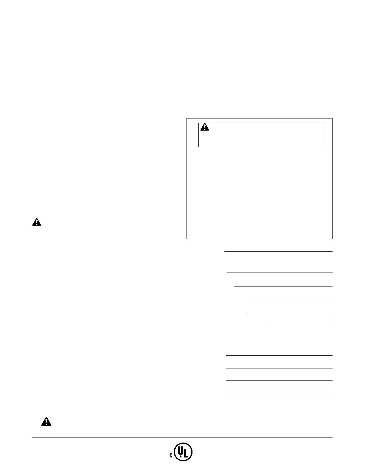
■■ For conventional firebox boilers refer to Table 2 and Figure 1 for recommended combustion
chamber dimension and typical floor and wall construction. If the recommended dimensions
cannot be provided, make length as long as possible and increase the width to maintain the floor
area. Where the floor are must be reduced, use the optional construction shown in Figures 2 or 3.
Figure 1: Typical Floor and Wall Construction
Standard Size Combustion Chamber up to 225 MBH per square foot
Figure 2: Typical Floor and Wall Construction
Alternate Size Combustion Chamber up to 275 MBH per square foot
Figure 3: Typical Floor and Wall Construction
Alternate Size Combustion Chamber up to 350 MBH per square foot (Maximum)
3
Page 4
■■
■■ For warm-air furnaces or Scotch Marine boilers with tubular combustion chambers, the
combustion chamber length must be great enough to exceed the lengths given in Table 2 by at
least 20%.
■■
■■ Combustion chamber proportions may be changed if necessary to avoid flame impingement on
critical parts such as drop sections in cast iron boilers or the heat exchanger surfaces of a warmair furnace. If sustained flame contact cannot be avoided, protect the surfaces with 2
1
/2" or
firebrick.
■■
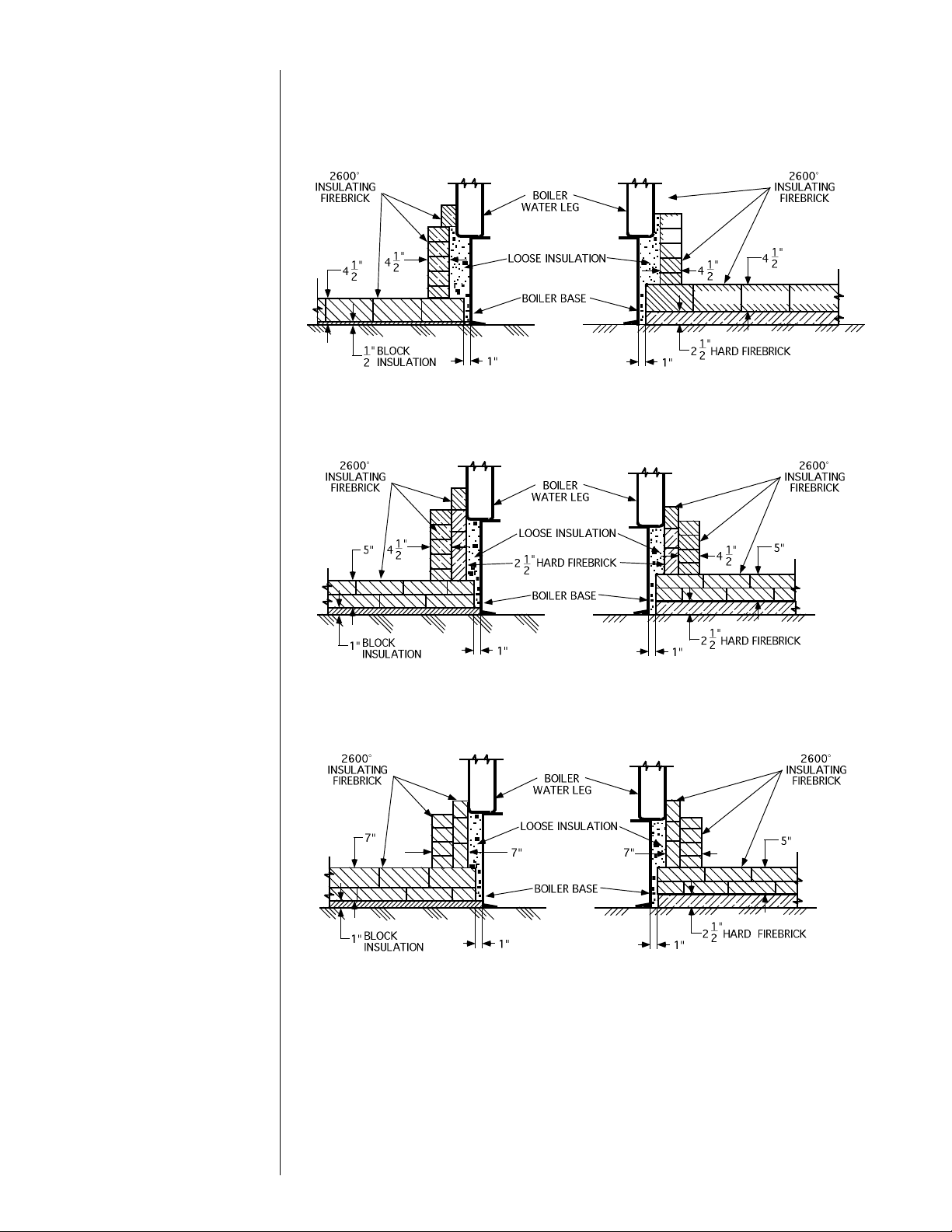
■■ The burner nozzle must not extend into the combustion chamber. It should be sealed into the
opening as shown in Figure 4. The burner mounting to the appliance front must be rigid and
sealed with
1
/4" soft refractory sheet or rope. See Figure 5 for mounting flange dimensions.
■■
■■ Allow a space of about 1" between the edges of the floor brickwork and the appliance base to
allow for expansion and creep. Where wall construction is such that both ends butt against rigid
appliance parts such as the base of a water leg, allow
1
/4" space between bricks every four feet
or so for expansion joints, particularly when reduced size combustion chambers are used.
Firing Door Installations
■■
■■ Greater care in planning will be required for firing door applications since flame impingement
on heat exchange surfaces is more probable. Do not fire a boiler containing a drop section
directly in the path of the flame, or over the water grate in a smokeless type boiler. The firebox
length must be great enough to exceed the combustion chamber lengths given in Table 2 by at
least 20%.
■■
■■ When raising the floor, maintain sufficient firebox volume to limit the heat release per cubic
foot to 50 MBH or less. Use the entire floor as a combustion chamber and cover any water leg
base to 6" from the bottom to avoid firing areas filled with sediment. Floor construction should
conform to Figures 1, 2 or 3.
■■
■■ The burner mounting in the door must be rigid and refractory lined as shown in Figure 9. The
burner nozzle must not protrude directly into the combustion chamber. The refractory liner must
be flush with or extend beyond the burner face as shown in Figure 4. A sheet metal rim should
encase the refractory up to the inside of the boiler wall. It should be intermittently bent inward to
retain the refractory or other means of anchoring should be provided. A refractory felt blanket
can be used in lieu of castable refractory, which will simplify construction at the burner entry.
IV Combustion Chamber
Continued
Figure 4: Construction at Burner Entrance
4
C
L
Page 5

IV Combustion Chamber
Continued
Detailed information is available on request.
■■
■■ Since firing door installations will generally leave no openings for flame observation, a peep
sight must be installed in the burner mounting plate.
Maximum
Input
MBH
685
1,125
1,750
2,250
2,500
3,000
3,500
4,000
5,000
6,000
Width
17"
21"
25"
27"
29"
32"
36"
39"
43"
45"
Length
33"
41"
50"
54"
58"
64"
72"
78"
86"
90"
C/L to Floor*
8"
10"
12"
12"
12"
12"
12"
12"
14"
14"
Recommended Combustion
Chamber Dimensions
Table 2: Recommended Combustion Chamber Dimensions
Figure 5: Mounting Flange and Burner Nozzle
Figure 6: Conventional Boiler—Large Firebox
* Dimension given is from centerline of burner nozzle to combustion chamber
floor.
5
Page 6

Figure 7: Conventional Boiler—Small Firebox
Figure 8: Tubular Combustion Chambers
Figure 9: Firing Door Installation in Three Pass Boiler
IV Combustion Chamber
Continued
6
Page 7

V Chimney and Flue Pipe
The chimney should be inspected for unsafe conditions such as deteriorated masonry
and excessive soot or other blockage or potential blockage.
■■
■■ All combustion air is furnished by the Unipower burner, and therefore the only function of the
chimney is to vent the flue products.
■■
■■ For the conventional appliances where a slight negative pressure in
the combustion chamber is desirable, the chimney and flue pipe sizes
given in Table 3 are recommended. Where chimney height exceeds
15 feet, a draft control should be installed per Figure 10 and set to
produce a draft of approximately .04" W.C.
■■
■■ The barometric draft control should be of the double swing type,
which opens freely outward to afford downdraft protection
regardless of the setting made to the balancing weights for updraft
control. For a chimney of the recommended diameter in Table 3, the
draft control should be sized from 80% to 100% of the flue pipe
area, or per manufacturer's recommendations. It should be located in
the same room as the heating appliance, clear of any obstruction
which could interfere with its operation.
■■
■■ The flue pipe must be of durable construction, preferably
galvanized steel of sufficient strength, and securely supported. When
passing through a combustible wall or partition, ventilated metal
thimbles or suitable insulation and clearances must be provided to
keep surface temperatures of exposed combustible material below 194° F.
■■
■■ Do not arbitrarily reduce the flue pipe size, since a back pressure can build up in the
combustion chamber, leading to possible
leakage of flue products into the building.
However, if an undersized flue pipe or
chimney must be used and the appliance
is carefully sealed, or if it is built for
pressurized firing, the areas can be
reduced to accommodate 14,000 BTU per
square inch or more, particularly if the
chimney is 30 feet high or more.
■■
■■ If the flue pipe must be extra long, the
area of the pipe and chimney should be
increased, or the chimney height should
be increased, or both. Never allow the
horizontal length of the flue pipe to
exceed the height of the chimney.
■■
■■ If the chimney is of greatly excessive
height, draft may be so great as to cause
the barometric draft control to float in the
wide open position all the time, destroying
its effectiveness. The use of an adjustable
non-floating damper in the flue pipe will
prove useful in this instance by reducing
the draft to a point where the barometric
draft control can operate effectively. It
should be placed in the flue pipe between
the barometric draft control and the
chimney. Its' area must be less than that
of the flue pipe so that total blockage of
the flue pipe is impossible. The
construction of the flue pipe damper and
its adjusting mechanism must be rugged,
so that no flutter or vibration occurs. After
final setting, the damper must be welded
into position to prevent tampering.
■■
■■ In the case of a motorized flue pipe
damper or mechanical flue exhauster, an
electrical interlock must be provided—see
Section VI Electrical.
■■
■■ The information given in this section is by necessity of a general nature. Special cases may
require special treatment.
Maximum
Input
MBH
Flue
Pipe
Diameter
900
1,250
1,750
2,250
3,000
3,750
4,500
6,000
12"
14"
16"
18"
20"
22"
24"
26"
Table 3: Recommended
Size of Flue Pipe and
Chimney
Figure 10: Draft Hoods
Figure 11: Barometric Dampers
7
Page 8

VI Electrical
VII Gas Piping
■■
■■ The burner when installed, must be wired and grounded in accordance with local codes or in
the absence of local codes, with the National Electric Code ANSI/NFPA No. 70-latest edition.
In Canada, refer to CSA Standard C22.1, "Canadian Electrical Code Part 1" and/or local
codes.
Refer to the separate wiring diagram included with this burner for specific wiring
details. The wiring diagram number for your burner is listed on the front cover of this
manual.
■■
■■ When wiring, be sure that the electrical power take-off is connected to a permanently live
circuit and that the burner is electrically grounded. Use copper conductors not lighter than those
given in Table 4.
■■■■
Standard Unipower A-
Series burners are equipped
with Honeywell Flame
Safeguards.
■■
■■ The RM7895 Flame
Safeguard provides pre-purge
and intermittent pilot
operation. See Section I
Specifications for application.
When mounting the chassis,
be sure electrical power has
been turned off. Check all
plug-in components for
security.
■■
■■ The RM7840M Flame Safeguard provides pre- and post-purge and interrupted pilot operation.
See Section I Specifications for application. Burners over 2500 MBH are equipped with a highlow gas pressure switch which prevents operation if gas line pressure exceeds or falls below
certain preset limits.
■■
■■ For further information on both flame safeguards, see Part 2 Service.
■■
■■ Where safe operation of the burner depends on factors external to the burner, an interlock
must be included which will prevent or delay burner operation until safe conditions exist. For
example, in the case of a motorized flue pipe damper or mechanical flue exhauster, the initial call
for heat must first energize the damper or exhauster motor, with burner start-up following only
when the above components are in effective operation as monitored by flow or draft pressure
switches in the flue pipe. If burner operation is made dependent on damper or exhauster control
relays, the system must "fail safe" so that malfunction or failure of these components will not
result in unsafe operations of the burner. See wiring diagrams for proper location of auxiliary
controls.
■■
■■ For the usual low pressure gas supply system, i.e. 5" to 14" W.C., use Table 5 to find the
recommended gas line size.
■■
■■ Piping follows normal practice and should be arranged as shown in Figure 12 with a drip leg at
the end of the vertical drop. The piping must be firmly supported independent of the
burner.
■■
■■ The burner is shipped with the main and pilot valve train completely assembled except for the
manual gas valves and regulators which should be mounted in a location convenient to the
burner. If the main gas train must be rearranged because of space limitations, maintain the
relationship of the components.
■■
■■ The gas line
pressure must be
within the limits
given in Section I
Specifications. If
higher than normal
gas delivery pressure
is encountered, as is
the case in many
industrial plants, the
gas line size may be
reduced to allow for
a greater pressure
drop (use the
multipliers given in
Table 5 for the
allowable size
variations) however, the size must be sufficient to deliver burner rating pressure.
Motor
H.P. Fuse Wire
115/1/60
Fuse Wire
230/1/60
Fuse Wire
230/3/60*
1
/
3
1
/
2
3
/
4
11/
2
2
30A
30A
45A
65A
75A
#14
#14
#12
#10
#10
#14
#14
#14
#12
#12
15A
15A
25A
35A
40A
—
—
#14
#14
#14
—
—
15A
15A
20A
Table 3: Fuse and Wire Sizes
* When 3 phase motor is used, the 120V. 1 phase control circuit
should be fused for 10A minimum and wired with #14 conductors.
Figure 12: Gas Piping Schematic
8
Page 9

VII Gas Piping Cont.
VIII Burner Start-Up
■■
■■ In higher gas pressure systems (over 14" W.C.) it is very important to install the proper
pressure reducing regulators at the burner. A high pressure regulator must be used in the line
ahead of the burner main manual gas valve, but it must be of the tight shut-off type and must
have a minimum flow regulating capacity suitable for the pilot (20,000 BTU/hr.)
CAUTION: If the gas supply pipeline is to be pressure tested, it should be done
before the burner is connected in order to prevent damage to the burner pressure
regulators and main gas valve. Use air or inert gas under pressure (DO NOT USE
OXYGEN).
■■
■■ Before gas is turned into the system, a
check must be made to see that there
are no open fittings and to make sure
the burner main manual valve and pilot
manual valve are closed. Purge the gas
line up to the burner inlet. Discharge
purged gas outside of the building, do
not purge into the combustion chamber.
Each burner is supplied with an individual initial start-up procedure. The start-up
instructions number for your burner is listed on the front cover of this manual.
■■
■■ After the initial start-up procedure the following steps can be followed for routine start-up and
shut-down on a seasonal basis.
Extended Burner Shut-Down
1. Turn off burner switch.
2. Close main manual valve.
3. Close pilot manual valve.
4. Turn off line switch.
Burner Start-Up
1. Make sure line switch and burner switch are off.
2. Set controller to call for heat.
3. Open firing door.
4. Open main and pilot manual gas valves.
5. Depress flame safeguard reset button.
6. Reset low gas pressure switch (if used).
7. Turn on line switch.
8. Turn on burner switch and allow burner to run through firing cycle.
9. Close firing door.
10. Reset controller to desired setting.
Table 5: Recommended Gas Piping
* Multiplier for Propane: 1.57
** Multiplier for alternate pressure drops: 0.3" W.C.-.77,
1.0" W.C.-1.40, 2.0" W.C.-2.00, 4.0" W.C.-2.80.
Feet
From
Meter
11/4"
11/2"
2"
3" 4"
21/2"
Maximum Capacity for Natural Gas*
MBTU/hr. Based on 0.5" W.C. Pressure Drop**
Pipe Size
25
40
60
80
100
125
150
175
200
760
660
1175
1000
810
690
620
2375
1900
1520
1300
1150
1020
950
850
800
3900
3000
2400
2050
1850
1650
1500
1370
1280
6000
5300
4300
3700
3250
2950
2650
2450
2280
5500
5000
4600
9
Page 10

Part 2 Service
CAUTION: Do not tamper with the unit or controls. If trouble occurs contact your
serviceman.
CAUTION: Be sure that the main and pilot manual valves are closed and the burner
power supply is turned off before removing any parts for service. Do not push relay
contacts in manually.
■■■■
Maintenance of the burner box and nozzle is minimal, due to the simplicity of the parts and
the absence of small air or gas passages. An occasional inspection of the parts in contact with the
flame will suffice. The burner nozzle parts should show no severe loss of metal or warping.
■■
■■ If the burner mounting flange shows evidence of overheating, check the tightness of the
burner mounting. The burner is intended to be sealed into the appliance face as shown in Figure
4 to prevent blow-back of hot flue products around the nozzle and flange.
■■
■■ The pilot is of the premix, blast type. Undampered blower air is brought into the pilot body
through the air orifice where the proper amount of gas is added through the pilot gas orifice. The
mixture is discharged through the alloy flame retention pilot tip. The pilot is rated for an
approximate capacity of 20 MBH and a normal operating pressure of 2.5" to 4" W.C. for both
Natural Gas and Propane.
■■
■■ The pilot regulator is factory set for an outlet pressure of about 3
1
/2" W.C. which will be
suitable for average conditions. Do not indiscriminately increase orifice sizes. Pilot troubles are
rarely cured in this manner. Adjust the pilot as described in the start-up instructions included with
the burner.
■■
■■ The spark rod is located on the center line of the pilot and is arranged to arc to the inside of
the central port. Spark current is supplied by a 6000V, 20 milliampere (minimum) end point
grounded ignition
transformer.
■■
■■ Service of the pilot
will generally consist
only of inspection and
cleaning. Check that the
air tube, pilot body and
the tip ports are free of
lint and dirt and that the
pilot tip is free of serious
corrosion. The spark rod
insulator must be clean,
dry and free of cracks.
See Figure 13.
■■
■■ The high tension
cable for the spark
electrode should be
checked for cracks and
abrasions.
■■
■■ Proper operation of
the flame safeguard
depends on a reliable
current flow through
the flamerod, pilot
flame and the burner
frame. The flamerod
must be free of any
contact with conductive
burner parts. The
insulator must be clean, dry and free of cracks. While the rod is made of heat resistant alloy, it
may eventually deteriorate at the point of flame contact and should be replaced if it is seriously
corroded.
X Pilot and Flame Sensor
IX Burner Box and
Nozzle Assembly
Model
A50G
Air Orifice
Natural
Propane
5
/16" (Brass)
#45 (.082)
#47 (.078)
#50 (.070)
Pilot Orifice Sizing
9
/32" (Aluminum)
A52-A55G A73-A77G
Figure 13: Pilot Assembly
10
C
L
Page 11

XI Blower and Motor
XII Gas Pressure Regulator
XIII Main Automatic Safety
Shut-Off Valve
V48 Diaphragm Gas Valve
(Not for use in Canada)
V5055 Valve Body
with Motorized Actuator
■■
■■ No routine service is necessary on the blower system other than cleaning the blower wheel
when necessary.
■■
■■ Blowers using three-phase motors will run in either direction depending on the connection of
the power supply. On new installations, motor replacement or power supply disturbance, the
rotation must be checked. Corrections can be made by interchanging any 2 wires of the threephase power supply.
■■
■■ If replacement motors for standard burners are procured from a source other than Midco, they
should conform to the following specifications: 3450 RPM, Frame 56C, end mounted open motor
with ball bearings. Capacitor start and thermal overload protection if single phase.
■■
■■ Proof of blower operation is provided by the diaphragm type blower air switch, which must
close its normally open contacts and maintain them closed when the blower is running. A check
for proper operation can be made by disconnecting the air pressure tube during burner
operation, which should result in burner shut-down. In case of malfunction, it is recommended
that the air switch be completely replaced.
■■
■■ A three wire self-testing hookup of the air switch is used on burners equipped with flame
safeguards, such as the RM7840, which have a 120V air proving interlock circuit. The N.C.
contacts of the air switch are wired into the start interlock circuit, which prevents burner start-up
unless the air switch proves operational by returning to its normally off position after every burner
run. Failure of the burner to start may be caused by a faulty air switch.
■■
■■ The gas pressure regulator is used to automatically reduce and maintain constant gas pressure
at the burner.
■■
■■ To adjust the outlet pressure, remove the seal cap for access to the adjusting screw. Turning
the screw clockwise will increase outlet pressure, counter-clockwise will decrease outlet pressure.
■■
■■ The vent in the upper diaphragm case normally breathes only air and must be connected to the
outside air to prevent escape of gas into the building in case of a ruptured diaphragm. The vent
line must be of sufficient diameter, otherwise the restriction of air flow may cause sluggish
opening of the regulator. The effect can be checked by comparing main flame start-up time with
the vent line connected and unconnected.
The vent must never be connected to the burner or combustion chamber
■■
■■ Although regulators seldom require servicing, the most vulnerable part is the diaphragm.
Periodic service should be limited to a diaphragm inspection, which should be checked for
punctures of stiffness.
■■
■■ The Honeywell V48A diaphragm gas valve is of the slow opening type with a maximum closing
time of 5 seconds. It requires a bleed tube which discharges into the combustion chamber
adjacent to the pilot. Closing force combines a gas pressure differential, diaphragm weight and
spring.
■■
■■ For general service a check for gas tightness will suffice. Start the burner and observe through
at least one cycle to be sure the valve functions properly and that the main flame has
extinguished completely.
■■
■■ Leak test per Section XVI Special Equipment. If leakage is observed, turn off the electrical
power and the main manual gas valve, remove the diaphragm case and make the following
checks: (1) the diaphragm must be pliable, free of holes and must have sufficient slack when set
in position; (2) the valve seat must be free of gum, tar or other dirt and must be free of cuts,
nicks and worn spots.
■■
■■ If the valve fails to close, make sure power is off at the terminals and gas flow is in the
direction of the arrow on the valve body. When malfunction is determined to be caused by the
valve operator head, the operator head should be completely replaced.
■■
■■ If the valve will not open, make sure normal gas pressure is available at the valve, the bleed
line is unobstructed, and power is available at the terminals.
■■
■■ The Honeywell V5055 main valve body is of the slow opening, fast closing type and does not
require venting. It is powered by a motorized valve actuator which supplies the motive power for
opening and closing the valve. The V4055 Actuator is used for On-Off and Full Modulating
operation. The V4062 Actuator is used for both the On-Off control and to provide High-Low
firing rate control. The full open position should be reached in 26 seconds after energization, the
closed position in one second or less.
■■
■■ For general service, the valve should be checked for gas tightness and proper operation. If
leakage is detected, the valve seat should be examined for dirt, damage or obstruction.
■■
■■ For access to the valve for inspection and cleaning, turn off the electrical power and the main
manual gas valve, then loosen the two Allen setscrews in the actuator collar and remove the
actuator. Remove the valve bonnet assembly by removing the bolts holding it to the valve body.
Inspect the valve seat for dirt, cuts, nicks and other defects. Do not disassemble the valve bonnet.
The valve seat is not replaceable; if defective, the entire valve body should be replaced.
11
Page 12

V5055 Valve Body with
Motorized Actuator Cont.
XIV Automatic Gas
Valve Leak Test
XV Flame Safeguard
XVI Special Equipment
■■
■■ Do not disassemble the valve actuator, it is not field repairable. If malfunction occurs, replace
the entire actuator.
1. Turn off power to burner.
2. Fully close the manual test cock (located downstream of the gas input adjuster.
3. Remove the
1
/8" pipe plug from the test tap located:
a. with diaphragm valve (in one of the pipes nipples between the valve and test cocks, or
b. with motorized valve (in the bottom of the valve body on its downstream side, or in the
tee connecting the high gas pressure switch tube to the valve train.
4. Install a pet cock in the test tap and attach a short length of
1
/4" flexible tubing. The open
end of the tubing should be cut at a 45° angle.
5. Immerse the open end of the tubing to a depth of
1
/2" in a container of water.
6. Open the pet cock. If bubbles appear, wait until the rate stabilizes, then count the number
appearing in ten seconds. An excess of 23 bubbles over a ten second period (approximately
.023 CFH of gas) indicates that the valve should be repaired or replaced.
7. If there are two automatic gas valves in the valve train, check the downstream valve first and
then the upstream valve. Use the appropriate tap in one of the motorized valve bodies, or
when a diaphragm and solenoid valve are furnished, in the pipe nipple between the valves.
8. After the test is completed, be sure to replug the test taps and fully open the test cock.
■■
■■ Standard Unipower burners are equipped with a Honeywell RM7895 microprocessor based
burner control, employing a flame rectification system of flame detection. Burner construction for
special codes and/or insurance requirements such as Factory Mutual or Industrial Risk Insurers (IRI)
may require alternate controls. Refer to Section XV Special Equipment. A safe start and run
control sequence is provided with instantaneous response to presence or loss of flame signal.
Flame failure response time is 3 seconds. Pilot Flame Establishing Period (PFEP) is field selectable
from 4 or 10 seconds. The RM7895 features a pre-purge time (30 seconds for On-Off, 90
seconds for 2-Step or Modulating burners) and a plug-in amplifier. An airflow circuit is also field
selectable to allow either lockout or recycle upon loss of airflow. Five LED's (light emitting diodes)
are provided to display sequence information. Refer to the Honeywell RM7895 literature for
detailed operating information, configuration requirements, testing and service.
■■
■■ Special Equipment, such as high-low gas pressure switches, main valve, proof of closure
switches etc., can affect the start-up and operation of the burner. Refer to your burner wiring
diagram and specific start-up instructions, as well as equipment manufacturer's literature included
with the burner for further information.
■■
■■ If any doubt exists concerning burner operation when special equipment is involved, contact
the installing contractor or Midco International Inc.
Burner
Model 0" W.C. .25" W.C. .50" W.C. .75" W.C. 1.0" W.C.
A50G
A52G
A53G
A55G
A73G
A75G
A77G
1500
2000
2500
3000
4200
5000
6000
—
—
—
—
4200
5000
5800
1300
1700
2500
2800
4000
5000
5600
—
—
—
—
3850
5000
5400
*
1525
2500
2575
3650
5000
5200
Combustion Chamber Back Pressure
Table 6: Maximum Capacities at Specified Back Pressures
12
 Loading...