

Page 1

XL8 Control Centre
Quick Reference Guide
Midas,
Klark Teknik Building,
Walter Nash Road,
Kidderminster.
Worcestershire.
DY11 7HJ.
England.
Tel: +44 1562 741515
Fax: +44 1562 745371
Email: info@uk.telex.com
Website: www.midasconsoles.com
XL8 Control Centre - Quick Reference Guide
DOC04-XL8 Issue C - February 2007
© Telex Com munications (UK) Limited
In line with the company’s policy of continual improvement, specifications and function may be
subject to change without notice. This Quick Reference Guide was correct at the time of writing. E&OE.
Page 2

Page 3
IMPORTANT SAFETY INSTRUCTIONS
The lightning flash with arrowhead symbol within an equilateral triangle is
intended to alert the user to the presence of uninsulated “dangerous voltage”
within the product's enclosure that may be of sufficient magnitude to constitute a
risk of electric shock to persons.
The exclamation point within an equilateral triangle is intended to alert the user
to the presence of important operating and maintenance (servicing) instructions
in the literature accompanying the product.
1. Read these instructions.
2. Keep these instructions.
3. Heed all warnings.
4. Follow all instructions.
5. Do not use this apparatus near water.
6. Clean only with a dry cloth.
7. Do not block any of the ventilation openings. Install in accordance with the manufacturer’s
instructions.
8. Do not install near any heat sources such as radiators, heat registers, stoves, or other
apparatus (including amplifiers) that produce heat.
9. Do not defeat the safety purpose of the polarized or grounding-type plug. A polarized plug
has two blades with one wider than the other. A grounding type plug has two blades and a
third grounding prong. The wide blade or the third prong are provided for your safety. If the
provided plug does not fit into your outlet, consult an electrician for replacement of the
obsolete outlet.
10. Protect the power cord from being walked on or pinched particularly at plugs, convenience
receptacles and the point where they exit from the apparatus.
11. Only use attachments/accessories specified by the manufacturer.
12. Unplug this apparatus during lightning storms or when unused for long periods of time.
13. Refer all servicing to qualified personnel. Servicing is required when the apparatus has been
damaged in any way , such as power -supply cord or plug is damaged, liquid has been spilled or
objects have fallen into the apparatus, the apparatus has been exposed to rain or moisture,
does not operate normally, or has been dropped.
14. Use the mains plug to disconnect the apparatus from the mains.
15. “DO NOT EXPOSE THIS EQUIPMENT TO DRIPPING OR SPLASHING AND ENSURE THAT NO
OBJECTS FILLED WITH LIQUIDS, SUCH AS VASES, ARE PLACED ON THE EQUIPMENT”
16. “THE MAINS PLUG OF THE POWER SUPPLY CORD SHALL REMAIN READILY OPERABLE”
WARNING: TO REDUCE THE RISK OF FIRE OR ELECTRIC SHOCK,
DO NOT EXPOSE THIS APPARATUS TO RAIN OR MOISTURE AND
OBJECTS FILLED WITH LIQUIDS, SUCH AS VASES, SHOULD NOT BE
PLACED ON THIS APPARATUS OR EQUIVALENT.
AVIS: RISQUE DE CHOC ELECTRIQUE. NE PAS OUVRIR
CAUTION
RISK OF ELECTRIC SHOCK
DO NOT OPEN
Page 4

Page 5
Telex Communications (UK) Limited, Klark Teknik Building,
Walter Nash Road, Kidderminster. Worcs. DY11 7HJ. England.
Tel: +44 1562 741515 Fax: +44 1562 745371
www.midasconsoles.com
EU DECLARATION OF CONFORMITY
We, Telex Communications (UK) Limited of Klark Teknik Building, Walter Nash Road, Kidderminster,
Worcestershire, DY11 7HJ, declare that a sample of the following product:
to which this declaration refers, is in conformity with the following directives and/or standards:
Signed: ...................................... ............ Date: 5th February 2007
Name: Simon Harrison
Authority: Research and Development Director, Telex Communications (UK) Limited
Attention!
Where applicable, the attention of the specifier, purchaser, installer or user is drawn to special limitations of
use which must be observed when these products are taken into service to maintain compliance with the
above directives. Details of these special measures and limitations to use are available on request and are
available in product manuals.
Company registration No. 2414018. A subsidiary of Telex Communications Inc.
Product Type Number Product Description Nominal Voltage(s) Current Freq.
XL8 Control Centre 115V AC
230V AC
12A
6A
50/60Hz
Directive(s) Test Standard(s)
89/336/EEC Electromagnetic Compatibility Directive amended by
92/31/EEC & 93/68/EEC 73/23/EEC,
Low Voltage Directive, amended by 93/68/EEC
Generic Standard Using EN55103 Limits and Methods EN50081/1
Class B Conducted Emissions PAVI EN55103
Class B Radiated Emissions PAVI EN55103
Fast Transient Bursts at 2kV EN61000-4-4
Static Discharge at 4kV EN61000-4-2
Electrical Stress Test EN60204
Electrical Safety
EN60065 7
th
Edition
Page 6

Page 7

End-User License Agreement for Midas™ and Klark Teknik™ Software
IMPORTANT - Please read this document carefully before using this Midas™ or
Klark Teknik™ product. This is an agreement governing your use of software or
other machine instructions already installed on the Midas™ or Klark Teknik™
product, as well as other software that we provide for installation on the product.
The Midas™ or Klark Teknik™ product will not operate in accordance with its
documentation without this software.
THIS AGREEMENT ("AGREEMENT" OR "LICENSE") STATES THE TERMS AND CONDITIONS UPON WHICH
TELEX COMMUNICATIONS, INC. ("COMPANY") OFFERS TO LICENSE THE INSTALLED FIRMWARE,
SOFTWARE, AND/OR PROGRAM ("the SOFTWARE") WITH THE MIDAS™ OR KLARK TEKNIK™ CONSOLE
OR SIGNAL PROCESSING PRODUCT ("PRODUCT") IN WHICH IT WAS INSTALLED BY, OR PROVIDED
FOR BY, THE COMPANY. YOU ARE AGREEING TO BECOME BOUND BY THE TERMS OF THIS LICENSE. IF
YOU DO NOT AGREE TO THE TERMS OF THIS LICENSE, DO NOT USE THIS PRODUCT. PROMPTLY
RETURN THE PRODUCT TO THE PLACE WHERE YOU OBTAINED IT FOR A FULL REFUND. You agree to
notify any persons who you permit to operate this Product of the terms of this License, and to expressly
obligate them in writing to comply with these terms.
The installed software as supplied by the Company is licensed, not sold, to you for use only under the
terms of this License, and the Company reserves all rights not expressly granted to you. You own the
Product on or in which the Software has been installed by the Company, but the Company retains
ownership of all copies of the Software itself, including those stored on or in the Product.
1. License: This limited License allows you, and other persons you permit to operate the Product,
to use the Software only on the single Product unit in which it was installed.
2. Restrictions: (a) The Software and the accompanying written materials are copyrighted, and
contain trade secrets and other proprietary matter, including confidential information relating to
the specifications and performance characteristics of Company's products. The Software is
protected by state trade secret laws as well as U.S. and international copyright and intellectual
property laws and treaties. All rights to copyrights, trademarks and trade secrets in the Software
or any modifications to it are owned by Company. Unauthorized copying of the Software or any
portion thereof, or copying of the written materials, is prohibited. (b) You may not create,
market, distribute, or transfer copies of the Software to others or electronically transfer or
duplicate the Software, or rent, lease, or loan the Software, except in conjunction with the sale,
transfer, loan, rent, or lease of the Product on w hich it is installed, and subject at all times to this
License. YOU MAY NOT REVERSE ENGINEER, DECOMPILE, DISASSEMBLE, MODIFY, ADAPT,
PORT, OR TRANSLATE THE SOFTWARE OR CREATE DERIVATIVE WORKS BASED ON THE
SOFTWARE OR ANY ACCOMPANYING WRIT TEN MATERIALS. (c) In the event you violate any term
of this Agreement, all licenses granted herein automatically terminate and you must stop using
the Software and destroy any copies of the Software or remove them from the Product.
3. Limited Warranty: Subject to your installation of any Software updates issued by the Company
as described herein, the Company warrants that the Software shall cause the Product to operate
in compliance with the Product's material specifications and documentation for a period of
90 days from your purchase of the Product. The Company does not w arrant that the oper ation of
the Software will meet your requirements or operate free from error. The Company DISCLAIMS
ALL WARRANTIES AND CONDITIONS EITHER EXPRESS OR IMPLIED, INCLUDING THE
WARRANTIES OF MERCHANTABILITY, FITNESS FOR A PARTICULAR PURP OSE AN D
NON-INFRINGEMENT OF THIRD PARTY RIGHTS. You understand that the Company may update
or revise the Software and in so doing incurs no obligation to furnish such updates to you.
However, the Company may in its discretion make updates available from time to time upon such
terms and conditions as it shall determine. It is a condition of any warranty granted pertaining to
either the Software or the Product, that you install any such Software updates, as may be issued
from time to time by the Company for the Product or the Software, in accordance with
Company's instructions. You may view current Software updates at http://www.klarkteknik.com
and http://www.midasconsoles.com
Page 8

4. Limited Liability: THE LIABILITY OF THE COMPANY FOR ANY CLAIMS ARISING OUT OF THIS
LICENSE AND/OR BASED UPON THE SOFTWARE, REGARDLESS OF THE FORM OF ACTION, SHALL
NOT EXCEED THE GREATER OF THE LICENSE FEE FOR THE SOFTWARE OR THE COST OF THE
PRODUCT. IN NO EVENT SHALL TELEX BE LIABLE FOR ANY LOSS OF DATA, LOST OPPORTUNITY
OR PROFITS, COST OF COVER, OR SPECIAL, INCIDENTAL, CONSEQUENTIAL, OR INDIRECT
DAMAGES, EVEN IF YOU ADVISE COMPANY OF THE POSSIBILITY OF SUCH DAMAGES. THIS IS
AN ESSENTIAL TERM OF THIS AGREEMENT AND YOU ACKNOWLEDGE THAT THE AMOUNT YOU
PAID FOR THE PRODUCT AND SOFTWARE REFLECTS THIS ALLOCATION OF RISK.
5. Other Third-Party Computer Programs: As referred to herein, the term "Software" refers
only to proprietary Midas™ or Klark Teknik™ Software, developed by Company, that has been
provided to you for installation on, or already installed in, your Midas™ or Klark Teknik™ Product.
In addition to this Software, you may have also been provided, at no additional charge, a v ersion
of the widely-available Linux software, which is a modular operating system made up of
hundreds of individual software components, each of which were written and copyrighted
individually by various parties (collectively, the "Linux Programs"). Each component has its own
applicable end user license agreement. Many of the Linux Programs are licensed pursuant to a
Linux End User License Agreement ("Linux EULA") that permits you to copy, modify, and
redistribute the Software. However, you must review the on-line documentation that shares a
directory or otherwise accompanies each of the Linux Programs included in this Product, for the
applicable Linux EULA. Nothing in this license agreement limits your rights under, or grants you
rights that supersede, the terms of any applicable Linux EULA. If you wish to receive a
computer-readable copy of the source code for the Linux programs that have been provided with
your Midas™ or Klark Teknik™ product, send a check or money order (no cash accepted), your
address, and $10.00 to cover the cost of optical media, postage and handling, to:
Telex Communications, Inc.
ATTN: Linux Programs CD for Midas™/Klark Teknik™
12000 Portland Ave South
Burnsville, Minnesota 55337.
In your request, indicate your Product's name and model number, serial number, and
version/release information. This offer made pursuant to the Linux EULA may expire according
to the terms of the Linux EULA, in which case your check will be returned to you or destroyed at
our option. Please note that the Linux distribution that may be available to you under this offer
consists of the Linux kernel only and does not contain any application software not
covered by the Linux EULA. Other updated Linux distributions containing application software
are widely available from a variety of Internet sources, and are often available at minimal or no
cost.
6. Termination: This License will terminate immediately if you violate any of the License terms.
Upon termination you must discontinue use of the Software, and either destroy, erase, or return
to Company all copies of the Software in your possession, custody or control, including those in
or on the Product.
7. General: This License constitutes the entire agreement between you and Company with respect
to this Software and supersedes any other communication (including advertising). If any
provision of this License is held unenforceable, that provision shall be enforced to the maximum
extent permissible so as to give effect the intent of this License, and the remainder of this
License shall continue in full force and effect. This License shall be governed by the laws of the
State of Minnesota, and the federal laws of the United States, without reference to conflict of
laws principles. You agree that the United Nations Co nv ention on Contr acts for the Internation al
Sale of Goods is inapplicable to both this License and to the sale of the Product.
Page 9

vii
XL8 Control Centre
Quick Reference Guide
Safety Precautions
Before installing, setting up or operating this equipment please ensure that
you have read and fully understand all of this section and the “IMPORTANT
SAFETY INSTRUCTIONS” at the front of this guide.
This equipment is supplied by a mains voltage that can cause electric shock injury!
The following special limitations must be observed in order to maintain safety and
electromagnetic compatibility performance.
Safety warnings
This equipment is fitted with two PowerCon® mains power sockets. For safety
reasons the earth leads must not be disconnected.
Signal 0V is connected internally to the chassis.
To completely disconnect this equipment from the AC mains, while observing
full safety precautions (see “Power” on page viii), switch off the five bay
isolator switches (rear of control centre) one at a time and then switch off the
mains at the two mains outlets that the PowerCon® mains leads are connected
to. It is now safe to isolate the control centre by unplugging the two
PowerCon® mains leads from rear of control centre.
Do not expose this equipment to dripping or splashing and ensure that no
objects filled with liquids, such as drinks glasses or cans, are placed on the
equipment.
To prevent shock or fire hazard, do not expose the equipment to rain or
moisture. To avoid electrical shock do not remove covers. Refer servicing to
qualified personnel only.
The power supplies - even the DC ones - have a high current!
General precautions
The following information gives basic safety precautions that should be observed to
reduce the risk of fire, electric shock and personal injury:
• Only properly trained service personnel familiar with this guide and with the
generally applicable safety regulations should service the equipment.
• Safety instructions detailed in the guide should be understood and properly
implemented.
• In the event of ground loop problems, disconnect the signal screen at one end of the
connecting cables. Note that this can only be done when the equipment is used
within a balanced system.
• Never operate damaged equipment and never operate equipment with damaged
cables.
• Any part that is damaged should be properly repaired or replaced. This must be
done by a fully trained and authorised service engineer.
• Observe all warnings, cautions etc. on any part of the equipment.
• Do not remove, hide or deface any warnings or cautions.
Page 10

viii Safety Precautions
XL8 Control Centre
Quick Reference Guide
Power
THE XL8 SYSTEM COMPONENTS SHOULD NEVER BE OPERATED WITH THE
MAINS EARTH DISCONNECTED!
Please note that the system power supplies contain LETHAL VOLTAGES greatly in
excess of the mains voltage and that its rails can produce extremely large currents that
could burn out equipment and wiring if shorted. All testing and servicing must ONLY be
carried out by approved service engineers.
This apparatus should only be operated with the power supply connected to ground via
the ground in the mains connector.
The internal power supplies are of the switch mode type that automatically sense the
incoming mains voltage and will work where the nominal voltage is in the range
100VAC to 240VAC.
Two PowerCon® mains inlets are provided on the rear panel. The correct leads for
connection in the area to which the unit was shipped are supplied with the unit. The
equipment should only be plugged into the mains outlets using the supplied leads.
We strongly recommend that, for safety and to optimise the life and performance of the
equipment, the mains cable plugs are removed from the power outlets when the
equipment is not to be used for extended periods of time or during electrical storms.
When removing the equipment’s electric plugs from the outlets, always hold the plug
itself and not the cable. Pulling out the plug by the cable can damage it.
Never insert or remove an electric plug with wet hands.
Do not insert or remove a PowerCon® connector into/from the rear of control centre
with mains power and any of the mains bay switches on. Y ou must make sure all mains
bay switches are off and mains is switched off at the power outlet(s) first.
When switching the five bay mains on/off switches on or off please make sure it is done
one at a time. It is important that you don’t switch on or off two or more
simultaneously.
Before switching the XL8 on or off, please make sure that all monitor loudspeaker
power amplifiers are turned off or muted.
Handling the equipment
Completely isolate the equipment electrically and disconnect all cables from the
equipment before moving it.
When lifting or moving the equipment, always take its size and weight into
consideration. If necessary, use suitable lifting equipment or transporting gear, or
sufficient additional personnel.
Do not insert your fingers or hand in any gaps or openings on the equipment, for
example, vents.
Avoid inserting or dropping foreign objects, such as paper, plastic, metal etc., into any
gaps or openings on the equipment, for example, vents. If this happens, immediately
disconnect the equipment from the AC mains; see “Safety warnings” on page vii. Then
have the equipment inspected by the manufacturer's qualified service personnel.
Do not press or rub on the sensitive surface of the GUI screens.
If the glass of the GUI screen is broken, liquid crystals shouldn’t leak through the break
due to the surface tension of the thin layer and the type of construction of the LCD
panel. However, in the unlikely event that you do make contact with this substance,
please wash it out with soap.
Page 11

Safety Precautions ix
XL8 Control Centre
Quick Reference Guide
Installation
Before installing the equipment:
• Make sure the equipment is correctly connected to the protective earth conductor of
the mains voltage supply of the system installation through the mains leads.
• Power to the equipment must be via a fused spur.
• Power plugs must be inserted in socket outlets provided with protective earth
contacts. The electrical supply at the socket outlets must provide appropriate
over-current protection.
• Both the mains supply and the quality of earthing must be adequate for the
equipment.
• Before connecting up the equipment, check that the mains power supply voltage
rating corresponds with the local mains power supply . The r ating of the mains power
supply voltage is printed on the equipment.
Location
• Ideally a cool area is preferred, away from power distribution equipment or other
potential sources of interference.
• Do not install the equipment in places of poor ventilation.
• Do not install this equipment in a location subjected to excessive heat, dust or
mechanical vibration. Allow for adequate ventilation around the equipment, making
sure that its fans and vents are not obstructed. To prevent excessive heating of the
equipment, avoid mounting it directly above power amplifiers or other devices that
radiate significant amounts of heat such as, radiators and heaters. Keep the
equipment out of direct sunlight.
• Do not place the equipment in an unstable condition where it might accidentally fall
over.
• Make sure that the mains voltage and fuse rating information of the equipment will
be visible after installation.
Audio connections
To ensure the correct and reliable operation of your XL8 Control Centre, only high
quality balanced, screened, twisted pair audio cable should be used.
XLR connector shells should be of metal construction so that they provide a screen
when connected to the console and, where appropriate, they should have Pin 1
connected to the cable screen.
Page 12

x Safety Precautions
XL8 Control Centre
Quick Reference Guide
Radio frequency interference
Class B device
This equipment has been tested and found to comply with the limits for a Class B digital
device, pursuant to part 15 of the FCC Rules. These limits are designed to provide
reasonable protection against harmful interference in a residential installation. This
equipment generates, uses, and can radiate radio frequency energy and, if not installed
and used in accordance with the instructions, may cause harmful interference to radio
communications. However, there is no guarantee that interference will not occur in a
particular installation. If this equipment does cause harmful interference to radio or
television reception, which can be determined by turning the equipment off and on, the
user is encouraged to try to correct the interference by one or more of the following
measures:
• Reorient or relocate the receiving antenna.
• Increase the separation between the equipment and receiver.
• Connect the equipment into an outlet on a circuit different from that to which the
receiver is connected.
• Consult the dealer or an experienced radio TV technician for help.
Electric fields
Caution:
In accordance with Part 15 of the FCC Rules & Regulations, “… changes or
modifications not expressly approved by the party responsible for compliance
could void the user's authority to operate the equipment.”
Should this product be used in an electromagnetic field that is amplitude modulated by
an audio frequency signal (20Hz to 20kHz), the signal to noise ratio may be degraded.
Degradation of up to 60dB at a frequency corresponding to the modulation signal may
be experienced under extreme conditions (3V/m, 90% modulation).
Operation
To avoid electrical shock, never operate the equipment with the covers removed.
Safety equipment
Never remove, for example, covers, housings or any other safety guards. Do not
operate the equipment or any of its parts if safety guards are ineffective or their
effectiveness has been reduced.
Optional equipment
Unless advised otherwise, optional equipment must only be installed by service
personnel and in accordance with the appropriate assembly and usage regulations.
Special accessories
To comply with part 15 of the FCC Rules, any special accessories (that is, items that
cannot be readily obtained from multiple retail outlets) supplied with this equipment
must be used with this equipment; do not use any alternatives as they may not fulfil
the RF requirement.
Page 13

xi
XL8 Control Centre
Quick Reference Guide
Contents
Chapter 1 Introduction. . . . . . . . . . . . . . . . . . . . . . . . . . . . . . . . .1
About this guide . . . . . . . . . . . . . . . . . . . . . . . . . . . . . . . . . . . . . . . .1
XL8 Live Performance System overview . . . . . . . . . . . . . . . . . . . . . . . 2
Control centre . . . . . . . . . . . . . . . . . . . . . . . . . . . . . . . . . . . . . . . . .2
Bays . . . . . . . . . . . . . . . . . . . . . . . . . . . . . . . . . . . . . . . . . . . . . . . .3
Control surface layout . . . . . . . . . . . . . . . . . . . . . . . . . . . . . . . . . . . . 4
GUI . . . . . . . . . . . . . . . . . . . . . . . . . . . . . . . . . . . . . . . . . . . . . . . .5
Input bay GUI display . . . . . . . . . . . . . . . . . . . . . . . . . . . . . . . . . . 5
Mix bay GUI display . . . . . . . . . . . . . . . . . . . . . . . . . . . . . . . . . . .5
Output bay GUI display . . . . . . . . . . . . . . . . . . . . . . . . . . . . . . . . .6
Pull-out keyboard . . . . . . . . . . . . . . . . . . . . . . . . . . . . . . . . . . . . . . .6
Front and rear connections . . . . . . . . . . . . . . . . . . . . . . . . . . . . . . . .6
Chapter 2 Connections, Setting Up And Powering Up . . . . . . . . .7
Description of the XL8 connections . . . . . . . . . . . . . . . . . . . . . . . . . . . 7
Front and rear connector panels . . . . . . . . . . . . . . . . . . . . . . . . . .7
Connecting up the XL8 . . . . . . . . . . . . . . . . . . . . . . . . . . . . . . . . . . . 8
Cable type and function . . . . . . . . . . . . . . . . . . . . . . . . . . . . . . . 10
Manual set-up of unit IDs . . . . . . . . . . . . . . . . . . . . . . . . . . . . . . . . 11
Powering the XL8 system . . . . . . . . . . . . . . . . . . . . . . . . . . . . . . . . 12
To power up the XL8 system . . . . . . . . . . . . . . . . . . . . . . . . . . . . 12
To power down the XL8 system . . . . . . . . . . . . . . . . . . . . . . . . . . 12
Switching the XL8 Control Centre on/off . . . . . . . . . . . . . . . . . . . . . . 13
To switch on the XL8 Control Centre . . . . . . . . . . . . . . . . . . . . . . . 13
To switch off the XL8 Control Centre . . . . . . . . . . . . . . . . . . . . . . 14
Booting up . . . . . . . . . . . . . . . . . . . . . . . . . . . . . . . . . . . . . . . . . . . 14
Chapter 3 Getting Started. . . . . . . . . . . . . . . . . . . . . . . . . . . . . .15
Control surface layout . . . . . . . . . . . . . . . . . . . . . . . . . . . . . . . . . . . 15
Saving your work . . . . . . . . . . . . . . . . . . . . . . . . . . . . . . . . . . . . . . 15
Saving a show versus storing a scene . . . . . . . . . . . . . . . . . . . . . . 15
Working with the controls . . . . . . . . . . . . . . . . . . . . . . . . . . . . . . . . 16
To adjust a GUI control knob via glide pad/trackball . . . . . . . . . . . . 16
Navigating the inputs . . . . . . . . . . . . . . . . . . . . . . . . . . . . . . . . . . . 17
How input channels are displayed on the GUI . . . . . . . . . . . . . . . . 17
To select a bank of input channels . . . . . . . . . . . . . . . . . . . . . . . . 18
To select an input channel by typing in its number . . . . . . . . . . . . . 19
Setting a mic amplifier’s input gain . . . . . . . . . . . . . . . . . . . . . . . . . . 20
To set stage box gain/console gain . . . . . . . . . . . . . . . . . . . . . . . 20
Setting the high and low pass filters . . . . . . . . . . . . . . . . . . . . . . . . . 21
To set both high and low pass filters in . . . . . . . . . . . . . . . . . . . . . 21
Input equalisation (E zone) . . . . . . . . . . . . . . . . . . . . . . . . . . . . . . . 22
To EQ the input signal . . . . . . . . . . . . . . . . . . . . . . . . . . . . . . . . 22
Page 14

xii Contents
XL8 Control Centre
Quick Reference Guide
Input dynamics processing (D zone) . . . . . . . . . . . . . . . . . . . . . . . . .23
To set up a compressor/limiter . . . . . . . . . . . . . . . . . . . . . . . . . . .23
To set up a gate . . . . . . . . . . . . . . . . . . . . . . . . . . . . . . . . . . . . .24
VCA/POP groups . . . . . . . . . . . . . . . . . . . . . . . . . . . . . . . . . . . . . . .25
To assign input channels to a VCA/POP group . . . . . . . . . . . . . . . .25
To set up the name and colour of a VCA/POP group . . . . . . . . . . . .26
To recall a VCA/POP input group . . . . . . . . . . . . . . . . . . . . . . . . . .27
Navigating the outputs . . . . . . . . . . . . . . . . . . . . . . . . . . . . . . . . . . .28
To select the output screen . . . . . . . . . . . . . . . . . . . . . . . . . . . . .28
To select a bank of auxes or returns to the mix bay . . . . . . . . . . . .28
To select an output channel . . . . . . . . . . . . . . . . . . . . . . . . . . . . .29
Setting up a mix . . . . . . . . . . . . . . . . . . . . . . . . . . . . . . . . . . . . . . .30
To set up an aux mix . . . . . . . . . . . . . . . . . . . . . . . . . . . . . . . . . .30
To program a mix preset . . . . . . . . . . . . . . . . . . . . . . . . . . . . . . .32
Setting up the effects rack . . . . . . . . . . . . . . . . . . . . . . . . . . . . . . . .33
To add an effect . . . . . . . . . . . . . . . . . . . . . . . . . . . . . . . . . . . . .33
Routing an aux to an effect or output . . . . . . . . . . . . . . . . . . . . . . . .34
To route an aux . . . . . . . . . . . . . . . . . . . . . . . . . . . . . . . . . . . . .34
Simple routing to master stereo outputs . . . . . . . . . . . . . . . . . . . . . .35
Scenes (automation) . . . . . . . . . . . . . . . . . . . . . . . . . . . . . . . . . . . .36
To create a new show . . . . . . . . . . . . . . . . . . . . . . . . . . . . . . . . .36
To save a show . . . . . . . . . . . . . . . . . . . . . . . . . . . . . . . . . . . . . .37
To load a show . . . . . . . . . . . . . . . . . . . . . . . . . . . . . . . . . . . . . .37
To store a scene . . . . . . . . . . . . . . . . . . . . . . . . . . . . . . . . . . . . .38
To recall a scene . . . . . . . . . . . . . . . . . . . . . . . . . . . . . . . . . . . . .39
Naming inputs and outputs . . . . . . . . . . . . . . . . . . . . . . . . . . . . . . . .40
To change the name and colour of an input . . . . . . . . . . . . . . . . . .40
To change the name and colour of an output . . . . . . . . . . . . . . . . .40
Areas A and B (split surface/dual operation) . . . . . . . . . . . . . . . . . . . .41
Saving your show files to USB memory stick . . . . . . . . . . . . . . . . . . .42
To save a show file to a USB memory stick . . . . . . . . . . . . . . . . . .42
Troubleshooting . . . . . . . . . . . . . . . . . . . . . . . . . . . . . . . . . . . . . . .43
To check active master controller via the GUI . . . . . . . . . . . . . . . . .43
Page 15
1
XL8 Control Centre
Quick Reference Guide
Chapter 1: Introduction
The XL8 Control Centre is a user-friendly, state-of-the-art, high performance digital
console that forms an integral part of the XL8 Live Performance System, which has
been specifically designed for live use.
The XL8 Control Centre comprises a combined control surface and graphical user
interface (GUI) that provide an array of easy-to-use controls for precise manipulation of
audio. The control surface has been designed to emulate the fast access of an analogue
control surface by presenting things in a familiar, consistent and logical way so that
experienced analogue engineers can migrate easily to the new digital surface. This is
enhanced by visual representations on the GUI at the top of control surface, which also
provides extra functionality.
About this guide
This quick reference guide shows you how to connect up an XL8 Live Performance
System, switch on the XL8 Control Centre and then quickly familiarises you with its
basic operation in order to produce some audio.
For full details on connecting and setting up, operation, servicing etc., please refer to
the XL8 Control Centre Operator Manual, part number DOC02-XL8, which is available at
www.midasconsoles.com.
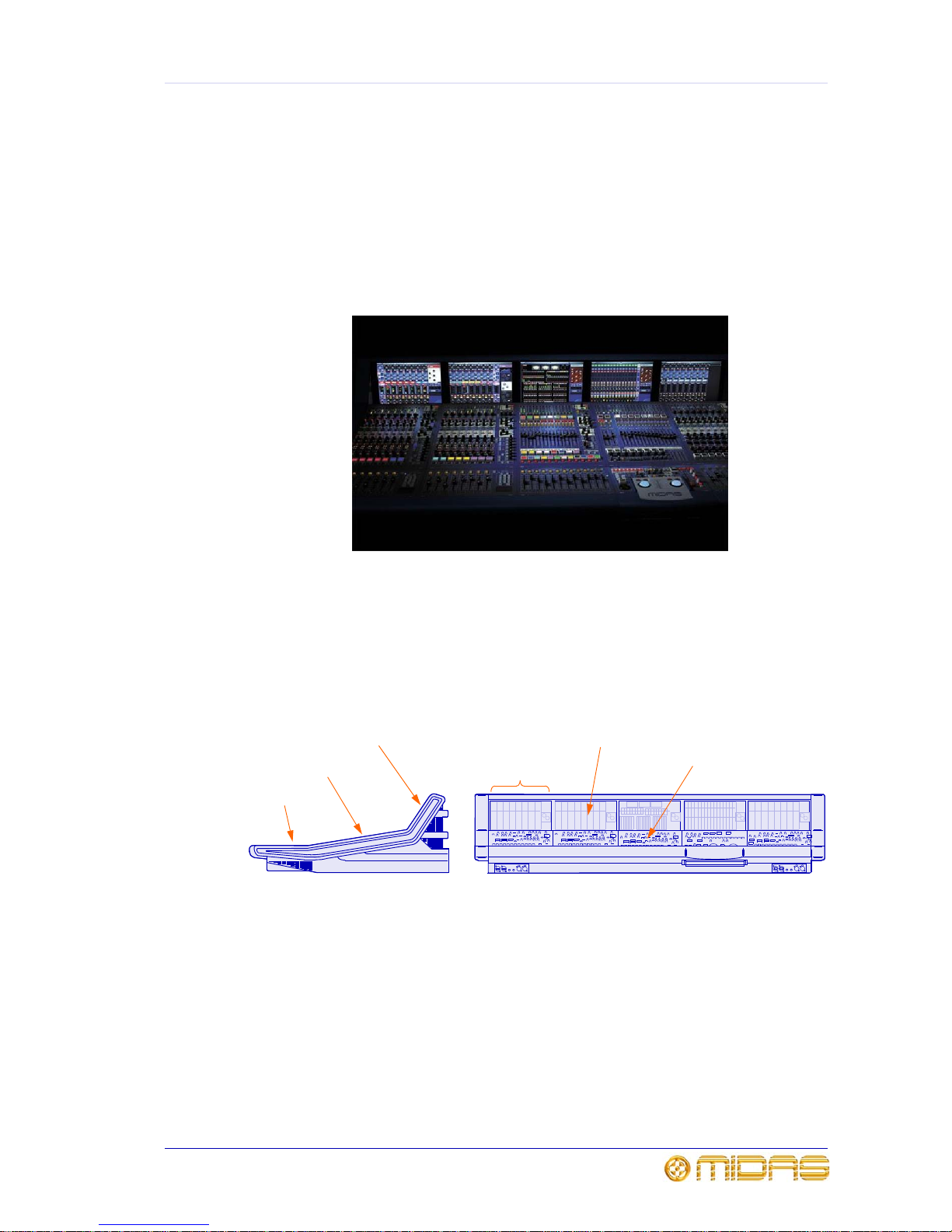
Front viewSide view
GUI screens
Control surface
Fader tray
GUI screen
Bay
Control surface
Page 16

2 Chapter 1: Introduction
XL8 Control Centre
Quick Reference Guide
XL8 Live Performance System overview
The XL8 Live Performance System is a very powerful and flexible audio processing
system that provides a complete solution for any audio mixing and signal distribution
application in a sound environment.
The XL8 Control Centre forms the core of the XL8 Live Performance System, which also
includes a number of 19” rack modules that are interconnected by a networked data
system. The network carries both proprietary control data and open architecture
AES50 digital audio, and uses readily available standard cabling and connectors.
Along with the XL8 Control Centre, there are four mic splitters, five I/O units, 10 DSP
units, two routers and a Klark Teknik DN9331 RAPIDE that, between them, form the
standard XL8 Live Performance System configuration.
The XL8 Live Performance System is tolerant of any single failure of hardware or
software. To achieve this the system employs dual redundancy, where a key
component has a identical redundant spare that is ready to take over should it fail.
Other failure scenarios are managed by the N+1 principle, where redundant
components form an acceptable fraction of the system, for example, one of the DSP
units in the rack is a redundant spare.
Control centre
The XL8 Control Centre is built on a robust Midas steel frame chassis similar to those
used for established Midas analogue products. The frame houses five bays, each of
which is a discrete hardware module that can operate independently of its neighbour.
Collectively, the bays provide the primary mixing needs of the engineer.
Each bay has its own power supply, control surface modules, control surface
processors, GUI processor and GUI screen. The control surface and GUI processors for
each bay are separately connected to the network on duplicated Ethernet links. Also
housed within each bay are dual redundant master control processors and dual
redundant high-speed network routers (eight AES50 connections each).
The control surface of the XL8 Control Centre is populated with instantly recognisable
controls that are logically distributed in major sections, so that all the controls you need
to access most of the time are always on the control surface, while the remainder are
only one action away. All I/O meters are permanently on display, both on the control
surface and the GUI (if configured), to give instant monitoring feedback. The layout
also allows two operators to work on the XL8 Control Centre simultaneously.
The principle of XL8 Control Centre operation is based on the concept of colours and
groups rather than ‘layering’ or ‘paging’, which is the case with most digital consoles on
the market today. With so many channels available it is far easier to remember them
by their group colour and name rather than by their channel number.
Multiple hardware faults are tolerated by the XL8 Control Centre without loss of audio
control due to the dual redundancy and N+1 methods incorporated in the system. This
is further helped by the modular nature of the bays and GUI independence. So if a
whole bay fails, others can take over or be used instead, and any of the GUI screens
can be used to operate the whole XL8 Control Centre, even if none of the control
surface hardware is working.
Page 17
Bays 3
XL8 Control Centre
Quick Reference Guide
Bays
The XL8 control centre has five bays, of which there are three types:
• Input Bays (3-off): Provide fast access to large numbers of faders and important
input signal processing controls. The bays are numbered 1, 2 and 3, in order from
left to right.
• Mix Bay: Gives fast access to large numbers of creative mix faders.
• Output Bay: Gives access to the matrix/master output mixes and monitor faders,
the automation central control and large quantities of complex signal processing
systems.
Each bay has a GUI screen at the top and a control surface below, which is subdivided
into a control area (shallow rake) and a flat (horizontal) area at the bottom that
contains faders, navigation zones, automation etc.
Figure 1: Bays
GUI screens
Control area
(shallow rake)
Fader tray (flat)
Bays
Mix OutputInput 1 Input 2 Input 3
Input bay
1 2 3
Mix bay Output bay
Page 18
4 Chapter 1: Introduction
XL8 Control Centre
Quick Reference Guide
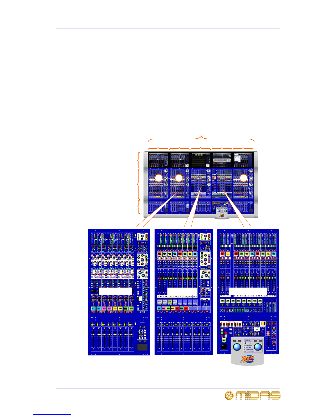
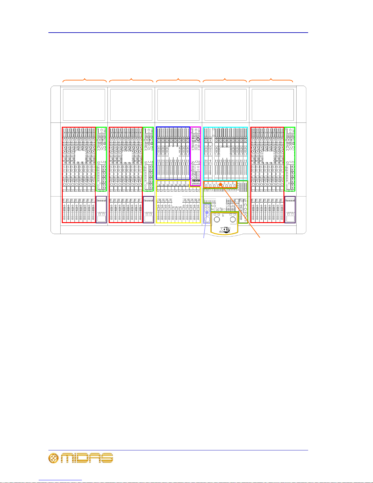
Control surface layout
The diagram below shows the main control surface areas of the five bays.
• A - input fast zone: contains operator’s ‘must have now’ controls in eight input
fast strips.
• B - input channel strip: provides a more comprehensive control by allowing
detailed adjustments to a single channel’s audio parameters; contains D-zone
(dynamic parameters) and E-zone (EQ parameters).
•
C - input navigation zone: for input GUI navigation via glide pad, and input
channel selection using an array of keys.
•
D - mix fast zone: auxiliary (aux) mix masters in eight dual-channel mix fast
strips.
•
E - output channel strip: provides a more comprehensive control by allowing
detailed adjustments to a single channel’s audio parameters.
•
F - VCA and POP groups: VCA and POP group select buttons and VCA faders.
•
G - output fast zone: output (matrix) mix masters in eight dual-channel output
fast strips, and also stereo (left and right) and mono masters.
• H - monitors: A and B signal path monitoring, communications and mute groups.
•
I - I-zone: operator-assignable effects controls.
•
J - automation: scene store/recall and system edit.
•
K - primary navigation zone: for mix bay and output bay GUI screen navigation
via trackballs, and screen access panel for quick access to certain GUI screen menu
options.
A A ABB B
D
E
G
F
Mix OutputInput 1 Input 2 Input 3
C
C
C
H
K
J
I
Page 19

GUI 5
XL8 Control Centre
Quick Reference Guide
GUI
The XL8 Control Centre has a graphical user interface (GUI) that provides a backdrop to
the control surface. The GUI comprises five screens that have been manufactured to a
high specification to give good definition in areas of strong light. This allows their
displays to be clearly visible in sunlight, which makes the XL8 ideal for outdoor
performances.
The GUI screen displays are designed to pictorially represent the layout of the control
surface, making them easy to follow and quickly understood. Not only do they reflect
what is happening on the control surface, but they also provide extra functionality via a
main GUI menu.
Each type of bay has its own specific GUI display and, generally, each GUI screen will
follow its bay navigation. However, the GUI screens are independent of their ‘home’
bay and can all perform the same tasks. This means that they can access any display
in the system at any time, even if this temporarily detaches it from its default task. So,
you can use any GUI screen to access the GUI menu (click on home at the top
left-hand corner). This menu provides access to all the screens that you will require to
set up, configure, manage and operate the entire XL8 Control Centre, all from a single
drop-down list of easy to follow options.
The following subsections show the standard bay screen displays.
Input bay GUI display
Shows input fast zone containing a bank of eight input
channels, plus input channel strip on the right.
Mix bay GUI display
Option of two displays:
default dashboard screen
(immediate right) showing
all meters, or output
channel screen (far right)
with 16 mix fast strips
(masters have only three).
Both displays have an
output channel strip on the
right.
Mix bay Output bayInput bay 1 Input bay 2 Input bay 3
Page 20

6 Chapter 1: Introduction
XL8 Control Centre
Quick Reference Guide
Output bay GUI display
Default display is the
effects screen (immediate
right), but can be changed
to any of a variety of
screens commonly
required, such as input
channels, groups,
automation (far right),
monitors etc.
Pull-out keyboard
A QWERTY keyboard is situated underneath the output bay. It is fitted on a tray that
runs on sliders, which allow it to be pulled out for use and slid back out of the way when
not required. It is used mainly for inputting text on the output bay GUI screen, such as
during configuration or when using automation.
Front and rear connections
Connector panels on the front and rear of the XL8 Control Centre provide XL8 Live
Performance System interconnections that allow connection of peripheral devices, such
as keyboards, monitors, portable PCs, USB memory keys etc.
Front view of XL8
Pull-out keyboard
Page 21

7
XL8 Control Centre
Quick Reference Guide
Chapter 2: Connections, Setting Up And
Powering Up
Description of the XL8 connections
Front and rear connector panels
The XL8 has connector panels on the front and rear that house numerous types of
connector, which cater for the connection of mains power leads, 19” rack units, USB
memory keys, keyboards, headphones, talk mics, communications, external monitors
(input and output), KVM (keyboard, video and mouse) switches, intercoms, AES3
synchronisation, word clocks (75R) and monitors.
The rear panel also houses the mains power inlet and five mains on/off switches, one
for each bay. Mains power is supplied to the XL8 Control Centre via two PowerCon®
sockets.
Figure 2: Front and rear connectors on XL8 Control Centre
Front connectors
Rear
Front
Control centre - side view
Rear connectors
Page 22

8 Chapter 2: Connections, Setting Up And Powering Up
XL8 Control Centre
Quick Reference Guide
Connecting up the XL8
This diagram shows the network interconnections for a typical FOH XL8 system.
1
2
5
1
2
5
5 4 3 2 1
6 7 8 9
10
5 4 3 2 1
6 7 8 9
10
5 4 3 2 1
6 7 8 9
10
1
5 4 3 2 1
6 7 8 9
10
5 4 3 2 1
6 7 8 9
10
5 4 3 2 1
6 7 8 9
10
12345678
12345678
1
2
2
1
1
2
2
3
3
4
4
5
5
1
1
2
2
6
6
7
7
8
8
9
9
1010
1
1
2
2
3
3
4
4
5
5
6
6
7
7
8
8
9
9
1010
C
C
C
C
C
C
C
C
C
C
A
A
B
D
D
1
2
2
3
3
4
4
5
5
6
6
7
7
8
8
9
9
10
10
1
FOH XL8 Control Centre - rear
Stage rack 1
Stage rack 2
X
Y
Note:
All connections are dual
redundant, so the
system can operate
quite normally using
either the X or Y cables.
Page 23

Connecting up the XL8 9
XL8 Control Centre
Quick Reference Guide
X router’s AES50 audio - bank 0 connectors to
AES50 audio - A X connector on mic splitters and
AES50 audio X connector on I/O boxes
Control centre AES50 audio Y connectors to
FOH rack I/O unit AES50 audio Y connectors
33
44
66
22
11
A
A
B
B
B
1
1
1
1
1
1
1
1
1
1
Stage rack 3
FOH rack
Control centre AES50 audio X connectors to
FOH rack I/O unit AES50 audio X connectors
Control centre snake/optical X and Y
connectors to appropriate X or Y router’s
snake/optical connector
Control centre snake/CAT6e X and Y
connectors to appropriate X or Y router’s
snake/CAT6e connector
X router’s AES50 audio - bank 1 connectors
to AES50 audio X connector on DSP units
Y router’s AES50 audio - bank 1 connectors to
AES50 audio Y connector on DSP units
X router’s Ethernet control connectors to
Ethernet control X connectors on DSP units
Y router’s Ethernet control connectors to
Ethernet control Y connectors on DSP units
Y router’s AES50 audio - bank 0 connectors to
AES50 audio - A Y connector on mic splitters and
AES50 audio Y connector on I/O boxes
A
Mic splitter
B
I/O box
Link DSP backbone (cables linking connectors
1-1 and 6-6 are non-standard lengths)
1
33
B
C
DSP unit
D
Router (X and Y)
Main cable
Duplicate cable
Note: A description of cable type and function can be
found in “Cable type and function” on page 10.
Key
Note:
For connections specific to the 19” rack units, please
refer to their respective operator manuals
Page 24

10 Chapter 2: Connections, Setting Up And Powering Up
XL8 Control Centre
Quick Reference Guide
Cable type and function
Table 1 below shows the type, terminations and function of the XL8 system’s
interconnecting cables. Please read the table in conjunction with the network
interconnections diagram on page 8.
Table 1: System interconnecting cables - type and function
Key Socket and
Connector
Cable
Type
Socket and
Connector
Description
Control centre
Cat5
I/O unit
AES50 audio, X - X.
Carries a bi-directional
combination of 24 channels of
96KHz audio plus 5Mbs of control
data.
Control centre
Cat5
I/O unit
AES50 audio, Y - Y.
Carries a bi-directional
combination of 24 channels of
96KHz audio plus 5Mbs of control
data.
Control centre
Optical
Router
Optical ‘snake’.
Carries a bi-directional
combination of 192 channels of
96KHz audio plus 200Mbs of
control data.
Control centre
Cat6e
Router
Cat6 ‘snake’.
Carries a bi-directional
combination of 192 channels of
96KHz audio plus 200Mbs of
control data.
Router
Cat5
DSP
AES50 audio - bank 1 - X.
Carries a bi-directional
combination of 24 channels of
96KHz audio plus 5Mbs of control
data.
Router
Cat5
DSP
AES50 audio - bank 1 - Y.
Carries a bi-directional
combination of 24 channels of
96KHz audio plus 5Mbs of control
data.
Router
Cat5
DSP
Ethernet control - X.
Carries standard 100bs Fast
Ethernet data.
Router
Cat5
DSP
Ethernet control - Y.
Carries standard 100bs Fast
Ethernet data.
Router
Cat5
Mic splitter
AES50 audio - bank 0 - Y.
Carries a bi-directional
combination of 24 channels of
96KHz audio plus 5Mbs of control
data.
Router
Cat5
Mic splitter
AES50 audio - bank 0 - X.
Carries a bi-directional
combination of 24 channels of
96KHz audio plus 5Mbs of control
data.
DSP
3M
cable
DSP
link 0 - link 1.
Carries a proprietary data format
for connecting the DSP units
together to form the DSP loop.
1
RJ45 XLR RJ45 XLR
1
RJ45 XLR RJ45 XLR
1
Neutrik Opticon Neutrik Opticon
1
RJ45 XLR RJ45 XLR
1
RJ45 XLR RJ45 XLR
1
RJ45 XLR RJ45 XLR
1
RJ45 XLR RJ45 XLR
1
RJ45 XLR RJ45 XLR
1
RJ45 XLR RJ45 XLR
1
RJ45 XLR RJ45 XLR
1
50-way
connector
50-way
connector
Page 25

Manual set-up of unit IDs 11
XL8 Control Centre
Quick Reference Guide
Manual set-up of unit IDs
After connecting up your XL8 network system, you may need to set up the ID of each
mic splitter, I/O box and DSP unit connected in the XL8 system (although they are
normally factory configured). This is because units of the same type must all have their
own unique ID numbers. There is no need to switch on the control centre, as the
procedure can be carried out offline. The following example shows you how to set up
an I/O unit. This procedure is basically the same for each type of unit, although there
may be variations in their set up menus. Please refer to the unit’s operator manual for
more details.
1 Switch on the I/O unit by pressing the mains on/off switch on the rear panel.
2 After unit has powered up and the I/O’s control panel shows the default display, press the MENU button and
hold down for approximately two seconds to access menu mode.
3 Press the down arrow button to select the “Set ID” option (option 2).
4 Press SELECT to activate the “Set ID” option; the unit will show the currently selected ID number (line 2).
5 Use the up and down buttons to select the required ID of your unit. For example, for an ID of “15”, press the
down button 14 times.
6 When you have reached the required ID number, press SELECT to store the ID. The display will run through
a ‘store ID’ sequence by displaying “Trying ID” followed by “Saving new ID”, before taking you back to the
“Set ID” display. The ID number will have ceased to flash and will remain constantly on to show that it is
now currently selected.
7 Press MENU to exit.
Rear of I/O box
1
This number will
flash to indicate
that this option is
not currently
selected.
x14
6
3
4
7
5
x2 seconds
2
Page 26

12 Chapter 2: Connections, Setting Up And Powering Up
XL8 Control Centre
Quick Reference Guide
Powering the XL8 system
The following details the recommended power up and power down procedures for the
XL8 system.
To power up the XL8 system
Important Note:
DO NOT switch on the speaker sub-system until after the start-up of the XL8
system has been completed.
After all XL8 system interconnections have been made, start up the XL8 system:
1 Make sure that all of the XL8 system equipment is switched off, that is, the XL8
Control Centre, speaker sub-system, DL431 mic splitters, DL451 modular I/O
units, DL461 routers and DL471 DSP units.
2 Switch on the XL8 Control Centre; see “To switch on the XL8 Control Centre” on
page 13.
3 On the XL8 Control Centre, move all of the monitor and master channel faders to
the minimum position and mute all of the master channels. The master channels
can be found in the mix and output fast zones; see “Control surface layout” on
page 4.
4 Switch on the DL431 mic splitters.
5 Switch on the DL451 modular I/O units.
6 Switch on the DL471 DSP units.
7 Switch on the DL461 routers.
8 After the alert indicators (top centre of each GUI screen on the XL8 Control
Centre) turn green, switch on the speaker sub-system.
9 Switch on the audio source and start playing the audio.
10 On the XL8 Control Centre, check that the audio inputs are routed to the master
channels. Then unmute the master channels and gradually increase their faders
while listening to the sound levels from the speakers.
If there are no sounds at all from the speakers when the faders are at maximum, move
the faders to below the 0dB level and check if the audio is muted somewhere along the
input paths and also check that the individual speakers are switched on. If there is still
no sound from the speakers, contact Midas Technical Support; see the front of this
guide.
To power down the XL8 system
Important Note:
BEFORE switching off any of the XL8 system components, make sure to mute
the audio from the speakers and switch off the speaker sub-system.
1 Mute the audio from the speakers and switch off the speaker sub-system.
2 Switch off the DL431 mic splitters.
3 Switch off the DL451 modular I/O units.
4 Switch off the DL471 DSP units.
5 Switch off the DL461 routers.
6 Switch off the XL8 Control Centre; see “To switch off the XL8 Control Centre” on
page 14.
Page 27

Switching the XL8 Control Centre on/off 13
XL8 Control Centre
Quick Reference Guide
Switching the XL8 Control Centre on/off
To switch on the XL8 Control Centre
Caution!
Before switching on, check that all monitor loudspeaker power amplifiers are
turned off or muted.
After connecting up the audio cables, carry out the following:
Mains
outlet
Mains
plug
1
1 Plug the two control centre’s mains PowerCon® cables into the mains power outlets.
2 Insert the two mains PowerCon® connectors into the PowerCon® sockets on rear of control
centre, observing the WARNING abov e. Then lock each one by twisting P owerCon® connec tor
about 90° (1/4 turn) clockwise; you should hear a click to indicate that it has locked in place.
Check that both PowerCon® connectors are securely fitted.
3 On the control centre’s rear connector panel, switch on all five bay mains on/off switches, one
after the other. It is important that you don’t switch on two or more switches
simultaneously.
4 Control centre will boot up (see “Booting up” on page 14); the GUI will display the default
screens and all the controls will be set to default. You are now ready to start using the XL8
control centre.
4
x2
x5
3
2
PowerCon®
connector
WARNING!
DO NOT INSERT OR REMOVE A
POWERCON® CONNECTOR INTO/FROM
REAR OF CONTROL CENTRE WITH MAINS
POWER AND ANY OF THE MAINS BAY
SWITCHES ON. YOU MUST MAKE SURE
ALL MAINS BAY SWITCHES ARE OFF AND
MAINS IS SWITCHED OFF AT THE POWER
OUTLET(S) FIRST.
PowerCon®
socket
Rear of XL8 Control Centre
Page 28

14 Chapter 2: Connections, Setting Up And Powering Up
XL8 Control Centre
Quick Reference Guide
To switch off the XL8 Control Centre
To switch off the control centre, make sure you have saved any scenes or settings you
require and switch off the five bay mains on/off switches on the rear of the control
centre, one at a time.
Booting up
The XL8 Control Centre has two boot up modes, cold and hot.
Cold boot occurs with a brand new system that has never before operated as a system.
Cold boot determines the system configuration and sets up all the IP addresses and unit
names.
Hot boot is the normal mode of operation (even if the XL8 has just been loaded from a
truck and is physically cold!). Hot boot uses the configuration and names stored in the
system flash memory. A complete hot boot takes up to 30 seconds. Should the
configuration not match the previously stored settings the user is asked what action the
XL8 should take.
Page 29

15
XL8 Control Centre
Quick Reference Guide
Chapter 3: Getting Started
This section is intended as a quick guide to familiarise you with the controls of the XL8
Control Centre and to show you how to carry out basic operations to enable you to get
some audio out of it.
Please don’t forget that, although this system is a complex, high-tech piece of
equipment, it is very easy to use.
Control surface layout
During show time the screen functions that require fast access are controlled by control
knobs (rotary encoders), pushbutton switches, faders etc. More complex functions that
do not require this fast access are controlled by glide pad/trackball and navigation keys.
An integral keyboard pulls out from underneath the output bay to enable setting up,
configuration etc., on the output bay GUI screen. An external keyboard can be used on
any of the other bays, as each bay has a dedicated keyboard socket on the front of the
control centre.
The choice of controls provided by each bay type are prioritised by access time
importance. A fast zone area gives instant access to specific functions across the bay.
A channel strip to the right of the input and mix bays gives greater control of the
selected fast strip. Similarly, GUI screen displays are split into corresponding areas - a
fast zone on the left-hand side and a channel strip on the right - to make them easier to
follow.
Typically, the XL8 fast zone areas contain signal processing and routing levels for input
bays, but only routing level control on the mix and output bay channel panels. GUI
screen navigation tools (keys, glide pad, trackball etc.) are used to manipulate the
signal processing required for these paths. This distances these functions from the
mixing surface, thus allowing the operator to concentrate more on creative mixing. On
analogue systems this is the equivalent of the external processing racks. The exception
to this on the XL8 being the graphic EQ for monitor mixing, where fast access is once
again required; this is provided by the Klark Teknik HELIX RAPIDE DN9331 Graphic
Controller.
Saving your work
We recommend that you save your work while carrying out the following
procedures. Not only is this good practise during normal XL8 operation, but in
this instance it may save you from losing some set-ups that could prove useful
later on. To do this, create a new show now, as detailed in “To create a new
show” on page 36, and then continue reading through the remainder of this
section, following the instructions carefully. Save your work at convenient
points; see “To store a scene” on page 38 and “To save a show” on page 37.
Saving a show versus storing a scene
Storing a scene saves the current scene settings to the show file, which is also done
automatically every five seconds. The latest show file is stored in the XL8’s memory.
Although this memory is recalled on XL8 power up, in extreme circumstances, such as a
system failure, this may be lost. However, by saving a show you are copying it onto the
XL8’s solid-state disk, which provides you with a ‘permanent’ copy. We therefore
recommend that you save your work regularly.
Page 30

16 Chapter 3: Getting Started
XL8 Control Centre
Quick Reference Guide
Working with the controls
The control surface is populated with many familiar analogue-type controls. However,
the GUI-related ones, such as the glide pads and trackballs, may be new to you.
To adjust a GUI control knob via glide pad/trackball
Adjustments of controls, such as a control knob or fader, on a GUI screen are done via
the glide pads/trackballs in the input and primary navigation zones, respectively. Each
glide pad will only operate the GUI screen within its bay, whereas the left-hand
trackball in the output bay operates the mix bay GUI screen and the right-hand one
operates the output bay GUI screen. Operation of both glide pad and trackball is
basically the same as using a mouse on a PC, as illustrated in the following example.
1,3
Control knob on the GUI screen
rotates smoothly relative to the
adjustment
1 Move your finger on glide pad or trackball to move the GUI screen cursor until it is
positioned over the control knob you wish to adjust.
2 Using your other hand, press and hold down the sele ct button (le ft -h and butto n) to
select the control knob under the cursor; cursor on GUI screen disappears to show
that control knob is selected.
3 Adjust the control knob by moving your finger again on the glide pad/trackball,
while still holding down the select button.
4 Release select button when you have achieved the required value.
Note:
On the glide pad, you can also select by quickly
double-tapping on the pad itself instead of using the select
button, which may be more convenient as you only need to
use one finger to complete the task.
Trackball
Glide pad
1,3
2
2
Page 31

Navigating the inputs 17
XL8 Control Centre
Quick Reference Guide
Navigating the inputs
The XL8 Control Centre has moved away from the traditional digital methods of layering
and paging, which are used to manipulate the channels too numerous to all fit on the
GUI simultaneously. Instead, it utilises operator-configurable grouping and colour
coding, see “VCA/POP groups” on page 25.
How input channels are displayed on the GUI
Each standard input GUI screen usually displays a bank of eight consecutively
numbered input channels (unless a group is selected to the control surface). There are
a total of 12 banks that, between them, encompass the 96 inputs available. Input
channels are displayed across the GUI in ascending order from left to right, irrespective
of bay position.
To help you understand the operating principles of the XL8 it may be best to visualise
the control surface as if it were an analogue one, that is, in two dimensions with all 96
input channels laid out side by side. In this case all input channels are visible all of the
time and would look something like the one in Figure 3 (a massive beast!).
Figure 3: Theoretical analogue equivalent of the XL8 Control Centre
However, in reality the XL8 Control Centre has only five GUI screens and, in the
standard configuration, only three of these GUI screens are allocated to the input
channels; the other two are used for the mix and output bay displays.
There are two main methods for selecting an input channel to a bay’s control surface,
scrolling and by typing in its number, which are detailed in the following sections.
1-8 9-16 17-24 25-32 33-40 41-48 49-56 57-64 65-72 73-80 81-88 89-96
Banks of channels
Theoretical analogue equivalent o f the XL8
Page 32

18 Chapter 3: Getting Started
XL8 Control Centre
Quick Reference Guide
To select a bank of input channels
To select a bank of input channels to an input bay (input bay 2 in example below), press
the scroll by 8 left and right buttons in the input select panel (located in the input
bay’s input navigation zone). The buttons select the bank that they are pointing to, as
illustrated below. The LEDs in the input select panel represent the 12 banks of eight
input channels (96 inputs in total) and show which bank is currently selected to its input
bay.
Bank 41-48 is displayed
on input bay 2’s GUI
screen
Display changes
to bank 33-40
Display changes
to bank 49-56
25-32
33-40 41-48
1 2 3
33-40
41-48 49-56
1 2 3
41-48
49-56 57-64
1 2 3
Illuminated LED shows
which bank is currently
selected to its input bay
Input bay 2
Page 33

Navigating the inputs 19
XL8 Control Centre
Quick Reference Guide
To select an input channel by typing in its number
To select any input channel to an input bay, type in its channel number using the keys
in the input select panel in the input bay’s input navigation zone. The LED
representing the bank containing the currently selected input channel will illuminate.
The diagram below shows the result of the action on the input bay GUI screens, where
the other two input bay GUI screens change their display accordingly so that the banks
still run consecutively.
The three input bay GUI screens can each have an input channel selected at the same
time.
25-32
33-40 41-48
1 2 3
This shows the
bank containing
channels 33-40
selected to input
bay 2 (default
configuration)
89-96
1-8 9-16
1 2 3
1
2
1 Type the required channel number, for example, “5”.
2 Press ENTER. Illuminated LED bank indicator will change position accordingly.
Illuminated LED
shows which bank
of eight channels is
currently selected
to its bay’s control
surface
This shows the new bank,
containing the channel just
selected (that is, 5),
selected to input bay 2
(see GUI screen above)
Input bay 2
Page 34

20 Chapter 3: Getting Started
XL8 Control Centre
Quick Reference Guide
Setting a mic amplifier’s input gain
The XL8 Control Centre has two input gains per channel, one is the remote gain for the
DL431 mic box (stage box gain) and the other is the digital trim (console gain). All of
the input gain sections (control surface and input GUI screen) are interchangeable so
that you can swap control from stage box gain to console gain, and vice versa. This is
useful if you want to change the gain of more than one channel in a bank. By pressing
the gain swap button, you can select the type of gain you want to the input fast strips
and adjust them there via their gain control knobs.
To set stage box gain/console gain
1
1 Select stage box-type input gain control to the
input fast strips by pressing gain swap.
2 Adjust the gain trim control knob (in 2.5dB steps
from -2.5dB to +45dB) to required level to suit
Midas pre-amp characteristic. A suitable level
could be one that only just illuminates the yellow
LEDs.
3 Drive the mic amps for that ‘Midas colouration’;
feel free to overdrive if you want.
4 After you have achieved the required gain state,
swap back to the console gain display by pressing
gain swap again.
5 Adjust console digital trim (gives ±20dB
continuous trim) for preferred gain structure.
Please note that the control knob in the input
channel strip (as indicated) always controls the
alternative ‘swap’ to the ones in the input fast
strips.
6 Set analogue remotes for initial set-up, then
adjust digital trim for showtime.
Common gain control knob
on input GUI screen
4
Stage box input gain
Console input gain
1,4
2
5
Page 35

Setting the high and low pass filters 21
XL8 Control Centre
Quick Reference Guide
Setting the high and low pass filters
Select high and low pass filters. Each can be on or off and, when on, each has two
settings. These filters can also be set via the GUI.
To set both high and low pass filters in
1 In the gain trim section of the required input channel, select the hi gh and low pass fi lter section by pressing
the quick access button.
2 Press high pass filter button to enable high pass filter.
3 Press SLOPE to enable slope of 24dB (SLOPE button illuminates). Leaving the SLOPE button in the fully
out position (SLOPE button extinguished) gives a slope of 12dB.
4 Adjust high pass filter control knob to required value in the range 10Hz to 400Hz.
5 Press low pass filter button to enable low pass filter.
6 Press SLOPE to enable slope of 12dB (SLOPE button illuminates). Leaving SLOPE button in the fully out
position (SLOPE button extinguished) gives a slope of 6dB.
7 Adjust low pass filter control knob to required value in the range 2kHz to 40kHz.
1
2
3
5
4
7
6
To aid filter set-up, the control surface
settings for the high and low pass filters are
replicated on the GUI, which can also be
used to set up the filters using the
associated glide pad
S
e
l
e
c
t
s
r
e
q
u
i
r
e
d
c
h
a
n
n
e
l
.
.
.
.
.
.
a
n
d
s
e
l
e
c
t
s
h
i
g
h
a
n
d
l
o
w
p
a
s
s
f
i
l
t
e
r
s
s
e
c
t
i
o
n
t
o
G
U
I
c
h
a
n
n
e
l
s
t
r
i
p
Important:
Stage box hi pass: The remote stage box contains a 12dB/Oct 30Hz filter. It
is recommended that this is used at all times for o ptimum A/D performance.
However, it may be bypassed if extremely low frequency performance is
required, for example, when testing the system.
Graph shows the
filter effects
Page 36

22 Chapter 3: Getting Started
XL8 Control Centre
Quick Reference Guide
Input equalisation (E zone)
Use EQ to equalise the input signal via the treble, hi-mid, lo-mid and bass filters, which
are situated in the input channel strip’s E zone. Treble and bass each have a
parametric filter option and three specific shelving modes. Feedback for EQ is via GUI
screen only.
To EQ the input signal
bright
classic
soft
deep
classic
warm
1
2
3a
4
3b
3c
2b
E zone
Input fast strip
1 In the required input fast strip, press EQ to switch on EQ.
2 Select the required filter, that is, treble, hi-mid, lo-mid (as in this example) or bass, by pressing its quick access
button on the input fast strip or by using the bass and treble up and down buttons on the E-zone.
3 Apply EQ by adjusting the freq, width and gain control knobs in the E-zone, as required.
4 Audition the different filters, including the ‘minimum harmonic dis ruption’ typ es by scrolling through them, using the
SHAPE button (or by pressing MODE on the GUI channel strip). These filters are only available for treble (bright,
classic and soft) and bass (deep, classic and warm).
2a
4a
4b
Note:
“Bright” and “Deep” use psychoacoustic p henomena to generate steep s lopes that sound
natural. These filters are called “minimum harmonic disruption filters”.
Graph shows the
EQ effects
Page 37

Input dynamics processing (D zone) 23
XL8 Control Centre
Quick Reference Guide
Input dynamics processing (D zone)
This section deals with assigning compressor and gate dynamics processors using the
controls in the input channel strip’s D zone.
To set up a compressor/limiter
Use the D-zone’s controls to apply compression. There are four compressors available,
corrective, adaptive, creative and vintage, with each having the option of hard knee,
medium knee and soft knee.
1 In the required input fast strip, press ON in the comp section to switch the compressor on.
2 Press the quick access button in the comp section to select the compressor section.
3 Apply processing by using the controls in D-zone, for example, adjust the attack and release. You could set up
a limiter by using a high threshold and a steep ratio (greater than 5:1).
4 Audition different algorithms (hard knee, medium knee and soft knee) using the KNEE button.
5 Try different compressor types (corrective, adaptive, creative and vintage) using the MODE button.
2
1
3b
4
3d
3e
3c
3a
D zone
Input fast strip
5
Corrective
Adaptive
Hard Medium Soft
Creative
Vintage
Page 38

24 Chapter 3: Getting Started
XL8 Control Centre
Quick Reference Guide
To set up a gate
Use the D-zone controls to apply gating.
2
1
Input fast strip
D-zone
3b
3d
3c
3a
1 In the required input fast strip, press ON to switch the gate on.
2 Press the quick access button in the gate section to select the gate section.
3 Apply processing by using the controls in D-zone, such as, attack, release, threshold, ratio/range and hold.
3e
Graph shows the
gating effects
Page 39

VCA/POP groups 25
XL8 Control Centre
Quick Reference Guide
VCA/POP groups
VCA/POP groups allow simultaneous control over a number of channels. They also save
you having to remember channel numbers when you wish to select a particular channel
to a bay. VCA/POP group recall is via an array of group select buttons on the mix bay.
Channel group associations are chosen by you and, in addition, you can configure the
colour and legend of the LCD group select button to be instantly recognisable.
A VCA group can contain input and output channels, while POP groups can only have
inputs assigned to them. Only input channels are recalled to the surface; any outputs
recalled leave the output bay ‘unchanged’.
To assign input channels to a VCA/POP group
In the example below, two input channels (already named “Bass” and “Lead”) are
selected to the VCA group select button named “Guitar”. The following method is also
adopted for selecting channels to a POP group.
VCA group
select button
1 On the mix bay, press and hold down the VCA group select
button that you wish to assign the input channels to. The inputs
will jump to program mode.
2 While still holding down the VCA group select button, press the
LCD select buttons of the input channels you wish to assign to
the new VCA group. Scroll to new bank, if required.
3 Release the VCA group select button. The VCA group now
contains the input channel members you have just selected. To
recall the VCA group, see “To recall a VCA/POP input group” on
page 27.
Input channel
select buttons
1
2b
2a
Page 40

26 Chapter 3: Getting Started
XL8 Control Centre
Quick Reference Guide
To set up the name and colour of a VCA/POP group
You can change the default name of a VCA/POP group and configure the backlight
colour of its group select button to suit your own preference. This is done via the GUI
and also using the keyboard under the output bay.
1 Click on home (top left-hand corner of screen) to obtain the GUI menu.
2 Select Population Groups and then Group Sheet from the menu options; this will take you to the Groups
Sheet screen.
3 Choose a pre-configured name from the drop-down list by:
a) Clicking on the ‘pencil’ icon.
b) Dragging the slider to scroll the list up and down to view all of the names.
c) Clicking on the name of your choice, for example, “Ride”.
4 Alternatively, you can type in a new name for your VCA group. Do this by clicking in its name field - a white
flashing cursor will appear at the end of the current name - and typing in its new name via the keyboard
(maximum six characters). The keyboard pulls out from underneath the output bay.
5 Assign a backlight colour to the VCA group select button and background of name field on GUI by:
a) Clicking on the palette icon.
b) Clicking on your chosen colour to select it, for example, blue.
1
2b
POP groups are configured
here; the method is identical
to that used for configuring
the VCA groups
3a
5a
4
3c
5b
This button takes you to the
VCA Groups screen, where
you can also assign
input/output group members
Slider
3b
2a
Page 41

VCA/POP groups 27
XL8 Control Centre
Quick Reference Guide
To recall a VCA/POP input group
To recall a VCA/POP input group and select its members to the control surface, simply
press its group select button. These buttons can be colour coded and display group
name (if configured).
When a VCA/POP input group select button is pressed the group members are unfolded
to the three input bays. They are displayed left to right across the control surface in
ascending order. The first bay populated is input bay 2 and, when this is full, input
bays 1 and then 3 are filled. Population starts at the right-hand side of bays 1 and 2
and at the left-hand side of bay 3.
If a group has more members than visible channels, these can be selected to the
control surface by scrolling using the left and right scroll by 8 buttons shown below.
To deselect the VCA/POP group, press its group select button again; settings revert to
those when the group select button was last pressed. Recalling an other VCA/POP group
deselects the one currently selected.
If any of these LEDs flash, it means
there are current VCA/POP group
members within the respective
bank(s) that are not selected to the
control surface.
Use the left and right scroll by 8
buttons to select hidden group
members to the control surface
Page 42

28 Chapter 3: Getting Started
XL8 Control Centre
Quick Reference Guide
Navigating the outputs
Outputs are manipulated on the GUIs in a slightly different manner to the input
channels. The different types of output channel are accommodated on the mix bay GUI
in banks of eight dual-channels, ex c e pt in the case of the master outputs, which have
only three channels (two stereos and a mono).
To select the output screen
To swap from the dashboard screen to the output screen, and vice versa, click on the
screen swap button. The swap button is situated at the top of the screen, adjacent to
the GUI channel strip.
To select a bank of auxes or returns to the mix bay
To select a bank of returns or auxes to the mix bay control surface, press RET or AUX
as required.
Pressing a bank select button
selects that bank to the
control surface. This is
confirmed by its associated
LED in the detail active
section being illuminated.
Page 43

Navigating the outputs 29
XL8 Control Centre
Quick Reference Guide
To select an output channel
There are a number of ways to select an output channel, for example, you can:
a) Press the channel select button in the appropriate fast strip. Where the channel
select button controls two channels, the initial press selects the fast strip’s left
channel (shown at top of button) and a second press selects the right channel
(bottom of button). Pressing a channel select button in another fast strip
changes selection to the left channel in that strip and deselect the current one.
b) Scroll by one output channel at a time. You can scroll across all of the banks of
output channels, which have the following type order: returns; auxes; masters
(stereo left and right, and mono); and matrixes.
c) Press the appropriate select quick access button (left or right) within the
appropriate fast strip, which also selects that channel section to the mix bay GUI
detail area. With two channels per fast strip, the left-hand button selects the
lower numbered (odd) channel and the right-hand button selects the higher
numbered (even) channel.
First press selects
aux 1
Only one of these LEDs will be
highlighted to show which bank
is currently selected to the
control surface
a)
Second press
selects aux 2
b)
Scrolls right by
one channel
Scrolls left by one
channel
c)
1
2
Page 44

30 Chapter 3: Getting Started
XL8 Control Centre
Quick Reference Guide
Setting up a mix
XL8 has 32 configurable mix buses, each of which can be aux mixes, subgroups and mix
minus. The aux mixes can also be set up as stereo pairs or mono. 16 matrix outputs
can also be accessed directly from input channels via level controls, which gives the XL8
the ability to provide 48 discrete mixes, plus left, right and mono. To keep the control
surface manageable, access to these mixes is confined to two rows of control knobs
across the input fast zone, which can be scrolled up and down on a ‘virtual’ surface.
Identification and access of mixes is again by colour coding. Any pair of 48 mix buses
can be locked onto the control surface of the input bays on an individual channel-bychannel basis. So that the two most crucial auxes for each channel (most pertinent
effects auxes, main artistes’ foldback, etc.) can be available at all times.
To set up an aux mix
1 Select an aux to the mix bay; see “To select an output
channel” on page 29.
2 Select the bus mode section by pressing the quick access
button adjacent to the direct input section of the output
channel strip.
3 The illuminated mix LED on the mix bay GUI screen
(default) indicates that mono mix is selected, which will
be used throughout this example. (Y ou can scroll thro ugh
the mix options by pressing MODE. group is fader only
with no pre-fader and mix minus allows mute only with
all buses being initially muted. Stereo mix mode - with
mix selected and stereo LINK button on - is only
accessed from the odd numbered output channel of the
linked pair; top control knob becomes pan adjust and the
bottom one adjusts level.)
4 On an input bay, select the required input channel by
pressing its channel select button.
5 Select the mixes section of the input fast strip to the
GUI’s channel strip by pressing the (store) quick access
button. (The (store) button has another function when it
is used for setting up bus presets, see “To program a mix
preset” on page 32.)
6 Use the PRE button to select pre- or post-fader. PRE
button status is via GUI only and is shown in two ways
(see following page): as a ramp or bar in the fast strip, or
by the PRE button in the channel strip (mix section)
being illuminated or extinguished.
7 Press ON to route the aux mix from input to aux output.
8 Adjust signal level using level control knob; you can also
use the fader.
2
3b
3c
3a
Page 45

Setting up a mix 31
XL8 Control Centre
Quick Reference Guide
5
6
7
8
Illuminated aux numbers
indicate that this is the
selected pair
Ramp shows that this
signal is post-fader
Bar shows that this
signal is pre-fader
This transition point, where solid colours
change to translucent, indicates 0dB
across the eight auxes
Level indicators are
bright on selected
channel but dimmed on
inactive/muted channels
Matrix mix
Aux mix
Page 46

32 Chapter 3: Getting Started
XL8 Control Centre
Quick Reference Guide
To program a mix preset
Programming mix presets is a cumulative process, that is, you can continually add
mixes to the store without affecting the ones already there. Once a mix preset is
programmed, it will be displayed whenever the preset button in the mix select section
of the input channel strip is pressed.
8
1a
1 In an input bay’s channel strip , se lect the mix you re quire
(that is, aux or matrix) to the mixes section of the input
fast strips. Do this by using any combination of the AUX,
MTX, scroll by 8 and scroll pair buttons.
2 Press and hold down the set upper button in the mix
preset section. This allows you to select all of the odd
numbered mixes (top number) shown in the mixes
section of the input fast strips.
3 While holding down the set upper button, press (store)
at every input channel you wish to select to the preset.
4 While still holding down the set upper button, repeat
steps 1 and 3 for all other odd numbered mixes you with
to select to the preset.
5 Release set upper button. Presets are stored.
6 Repeat steps 1 to 5, inclusive, to add all even numbered
mixes, but press set lower instead of set upper.
7 When you release the set lower button, the even
numbered mixes are added to the odd numbered ones
already in the preset store. All programmed presets will
be selected to the input channels. To deselect them from
the input channels, press one of the AUX or MTX buttons,
for example, the 1-8 AUX button; this action does not
affect the stored presets.
8 Press preset to view programmed presets.
2
6
3
7
1b
1c
Page 47

Setting up the effects rack 33
XL8 Control Centre
Quick Reference Guide
Setting up the effects rack
To add an effect
3
1 At the mix bay GUI, click on home to obtain the menu
options.
2 Click on Rack Units and then Effects in the GUI menu to
select the effects screen.
3 Choose the location of your new effect from one of the 16
effects sections, then click within that section.
4 Click on the Change Device Type button.
5 In “Select Device Type” window, click on one of the
available device types, for example, “Phaser”. (The
effects in the list may be slightly different on your display ,
as devices may have been added or existing ones
replaced.)
6 Click OK.
7 Edit new device as necessary, that is, adjust control
knobs, make ‘virtual’ connections (patch); you can even
change the device name by clicking in the name field and
typing the new name via the output bay keyboard.
8 Click OK to exit. You can exit without saving your
changes by clicking on “X” at top right-hand corner of
device window.
1
Effect currently selected
to this section
4
5
6
8
2a
2b
Page 48

34 Chapter 3: Getting Started
XL8 Control Centre
Quick Reference Guide
Routing an aux to an effect or output
To route an aux
2
1 Select an aux to the mix bay; see “To select an output channel” on page 29.
2 Select the bus mode section by pressing the quick access button adjacent to the direct input section of the
output channel strip.
3 Click on the down arrow to the right of the aux output source field (adjacent to XLR socket) to obtain a
drop-down list containing output source names.
4 Click on the name of the output source you require, for example, the effect you have just set up in “Setting
up the effects rack” on page 33.
3
Page 49

Simple routing to master stereo outputs 35
XL8 Control Centre
Quick Reference Guide
Simple routing to master stereo outputs
To obtain audio, simply press the ST (stereo) button of an input fast strip in an input
fast zone or in the output channel strip. Then, while making sure nothing is muted and
master faders are up, you will have audio.
Page 50

36 Chapter 3: Getting Started
XL8 Control Centre
Quick Reference Guide
Scenes (automation)
You can create new shows, load existing ones and manage scenes within a show. This
is done via the output bay GUI screen using the automation option. The save function
allows you to regularly save the current show settings to prevent them from being lost.
To create a new show
1 Press the automation/filing button in the output bay’s primary navigation zone to obtain the automation
screen on the output bay GUI screen. (Pressing this button again accesses the Files screen.)
2 Alternatively, you can use the output bay GUI screen by clicking on home and then Automation. (This can
be done at any of the GUI screens.)
3 Click on NEW.
4 In the small window that has just appeared, click in name field underneath the “Enter new show name:”
prompt and type in the name of your new show via the keyboard. The keyboard slides out from under the
output bay; to access it, just pull it towards you.
5 Click OK; control surface settings reve rt to default. Y ou can now creat e and manage the scenes for your new
show. Don’t forget to save at regular intervals.
2a
3
1
2b
Page 51

Scenes (automation) 37
XL8 Control Centre
Quick Reference Guide
To save a show
The XL8 will indicate to you when there are show settings to be saved. It does this by
changing the background colour of the SAVE button to red, as shown below. To save,
simply click on the SAVE button. We recommend you save your show settings
regularly.
To load a show
Background of SAVE
button reverts to its
normal dark grey colour
to indicate show settings
are up-to-date
1 Click on LOAD.
2 In the “Load File” window that has just appeared, select the show you require and click on it.
3 Making sure the show file name you have just chosen now appears in the “Load this file ...” name
field, click OK to load the show file.
1
Page 52

38 Chapter 3: Getting Started
XL8 Control Centre
Quick Reference Guide
To store a scene
Scenes can be managed using a combination of the automation section (output bay) on
the control surface and GUI screen, or via GUI screen only. The buttons in the
automation section illuminate to show that they are active.
1 Click STORE.
2 In the new “Store” window, use the output bay’s trackball to place GUI screen’ s cursor over the name
field. Press the trackball’s select button to enter the name field. Type in new scene name via the
keyboard.
3 Below new scene name, select one of the following options by clicking on it (emboldened options are
enabled, while greyed out ones are disabled):
“Insert before scene”
“Store to empty scene”
“Store to next scene”
“Overwrite scene”
4 You can use the keyboard to ty pe in any useful scene informati on in the “Scene Notes” window , if you
wish.
5 Click OK to save the scene.
1
1
2a
2b
Page 53

Scenes (automation) 39
XL8 Control Centre
Quick Reference Guide
To recall a scene
To recall a scene, use the “last”, “now” or “next” buttons, as required. The three
highlighted scenes are identified by their colour, where current scene is yellow, last
scene is red and next scene is green; these correspond to the colours of the three recall
buttons.
Last, now and next scenes are identified
by their highlight colour, which also
matches their respective recall button
Eye icon expands/collapses empty
scenes and point scenes
The jogwheel provides fast scene navigation. By rotating
it you can quickly scroll through the scenes one at a time,
in either direction; you can even go to the empty scenes
towards the end of the cue list. When you reach the end
of the cue list, it just wraps around to the beginning so
you can continue from the start again.
Page 54

40 Chapter 3: Getting Started
XL8 Control Centre
Quick Reference Guide
Naming inputs and outputs
For ease of identification, the name and background colour of the inputs and outputs
can be changed to suit user preferences. This is done via the sheet screens, which are
accessible via the GUI menu after clicking home and then selecting either Input
Channels or Mix & Outputs. The procedure is similar to that used for VCA/POP
configuration.
To change the name and colour of an input
To change the name and colour of an output
1
2a
2b
This button takes you to the input channels
screen; see page 19 for an example
From here, set up the mic input name and
colour; see “To set up the name and colour of
a VCA/POP group” on page 26.
1
2a
2b
This button takes you to the output channels
screen; see page 28 for an example
From here, set up the output name and colour; see “ To set up
the name and colour of a VCA/POP group” on page 26.
Page 55

Areas A and B (split surface/dual operation) 41
XL8 Control Centre
Quick Reference Guide
Areas A and B (split surface/dual operation)
In their default state, the input bays respond in a global manner to selections made on
any of their respective control surfaces, that is, they react as if they are ganged
together. In this case they are all designated as area A. However, the three input bays
can be split into two areas, A and B, both of which operate independently of each other.
The main reasons for doing this are for dual (two-man) operation or if a single operator
requires area B as a place to store important channels, just as a ‘channel 25’ would be
used on an analogue console.
Groups can be pre-selected to populate area A or B and a single group of inputs can
have members in both areas of the control surface. An operator can then recall them to
their own area to work on.
When operating area B, please remember to select the B option where
appropriate, particularly in the monitor section. Also note that solo B (also for
talkback) is totally independent of area B, which is used for navigation only.
For area B operation, choose the input bay that you wish to allocate as area B and press
its area B button (this is to the left of the input select panel, towards the bottom right
of the bay). Areas A and B can now be used independently of each other. A typical
configuration for area A and B operation is shown below, although any input bay can be
used as area B.
1 2 3
Area A Area B
Page 56

42 Chapter 3: Getting Started
XL8 Control Centre
Quick Reference Guide
Saving your show files to USB memory stick
After you are satisfied that your show file is how you want it, we recommend that you
save it to a removable storage device, that is, a USB memory stick. This provides a
valuable back up should the one stored in the XL8 be lost, for example, due to
inadvertent deletion or in the highly unlikely event of system failure.
To save a show file to a USB memory stick
1
3
4
2a
2b
1 Check which is the active USB key socket (its active LED
flashes) and insert the USB memory stick into this socket.
In this example, USB key 1 is active.
2 Click on home and then Files in the GUI menu to select
the Files screen. You may see an “Analysing...” message
in the “Removable Storage” panel, which means that the
Midas folder on the USB memory stick is being read.
3 When message has cleared, click on your show file (in
“Control Surface“ panel) to select it, which will now be
highlighted.
4 Click EXPORT.
5 A window with the message “Are You Sure you Want To
Export?” will appear; click OK to export the file. (Clicking
CANCEL cancels this operation.)
6 When your show file appears in the “Removable Storage”
panel it has been copied to the USB memory stick.
Remove the USB memory stick
Page 57

Troubleshooting 43
XL8 Control Centre
Quick Reference Guide
Troubleshooting
If you have followed all of the instructions for obtaining audio, but are not hearing
anything through the speakers, there are a number of quick checks you can go through
to make sure you haven’t missed out anything or that nothing is amiss. The following
provides a quick checklist:
• Make sure the appropriate ST buttons in the channel fast strips are on.
• Make sure the appropriate ST buttons in the source a/b panels (monitors section of
the output bay) are on.
• Make sure nothing is muted.
• Make sure no faders are set to minimum.
• Check that the VCA/group master faders are at unity gain.
• Use solo at selected points in the signal path to try and pinpoint where the signal is
being lost.
• Check for correct signal routing by making sure channel sources/destinations are
correctly assigned.
To make provision for the highly unlikely event that the active master controller (MC)
develops a malfunction, we recommend that you copy the show file to both MCs before
the performance. This will enable you to carry on with the show using the same show
file after carrying out an MC swap. To do this, copy the show file to a USB memory
stick (see “Saving your show files to USB memory stick” on page 42), switch active MC
(reset the MCs) and copy the show file to the other MC, which is now the active one.
To swap the MCs
1
, check via the GUI which MC is currently active (see “To check
active master controller via the GUI” on page 43) and press the appropriate MC
reset switch to shut down this MC. Then press the reset switch of the other MC
to activate it; the alert buttons at the top of the GUI screens will change to
green when the XL8 is ready for operation again.
The MC 1 and 2 switches, mc - 1 and mc - 2, respectively, are contained in a
bank of four (shown right) on the control surface, just to the right of the I zone.
(The other two switches are the router reset switches, which should not be
operated; a router swap is performed via the GUI.)
To check active master controller via the GUI
This is done by noting which of the two MCs is shown as green on the Diagnostics
screen on the GUI; the redundant one is red. In the following example, MC 1 is active.
1. The current method of resetting the master controllers involves the use of the reset buttons
on the control surface. In future XL8 versions this procedure will be under software control
and will be carried out via the GUI’s Diagnostics screen.
1
2
Page 58

44 Chapter 3: Getting Started
XL8 Control Centre
Quick Reference Guide
Page 59

Thank you for reading through this Quick Reference
Guide. We hope you found it useful. Please feel free
to send us your comments.
More detailed information on the XL8 can be found in
the XL8 Control Centre Operator Manual, part
number DOC02-XL8. This is available for download
from our website.
Our contact details and webite address can be found
at the front of this guide.
Page 60

Midas
Klark Teknik Building, Walter Nash Road,
Kidderminster. Worcestershire. DY11 7HJ. England.
Tel: +44 1562 741515, Fax: +44 1562 745371
Email: info@uk.telex.com
Website: www.midasconsoles.com
© 2007 Telex Communications (UK) Limited
 Loading...