

Page 1
(Visit midasconsoles.com for Full Manual)
Quick Start Guide
PRO X
Live Digital Console Control Centre and Audio System
Engine with 168 Input Channels, 99 Mix Buses and 96 kHz Sample Rate
A54-00001-28765
Page 2
2 PRO X
Terminals marked withthis symbol
carryelectrical currentof su cient
magnitude to constitute risk of electric
shock. Useonly high-quality commercially-available
speaker cables with plugs pre-installed. Allother
installation or modi cation should be performed only by
quali edpersonnel.
This symbol, wherever it appears,
alertsyou to the presence of uninsulated
dangerous voltage inside the
enclosure-voltage that may be su cient to constitute a
risk ofshock.
This symbol, wherever it appears,
alertsyou to important operating and
maintenance instructions in the
accompanying literature. Please read the manual.
Caution
To reduce the risk of electric shock, donot
remove the top cover (or the rear section).
No user serviceable parts inside. Refer servicing to
quali ed personnel.
Caution
To reduce the risk of re or electric shock ,
do not expose this appliance to rain and
moisture. The apparatus shall not be exposed to dripping
or splashing liquids and no objects lled with liquids,
suchas vases, shall be placed on the apparatus.
Caution
These service instructions are for use
by quali ed ser vice personnel only.
Toreduce the risk of electric shock do not perform any
servicing other than that contained in the operation
instructions. Repairs have to be performed by quali ed
servicepersonnel.
1. Read these instructions.
2. Keep these instructions.
3. Heed all warnings.
4. Follow all instructions.
5. Do not use this apparatus near water.
6. Clean only with dry cloth.
7. Do not block any ventilation openings. Install in
accordance with the manufacturer’s instructions.
8. Do not install near any heat sources such as
radiators, heat registers, stoves, or other apparatus
(including ampli ers) that produce heat.
9. Do not defeat the safety purpose of the polarized
or grounding-type plug. A polarized plug has two blades
with one wider than the other. A grounding-type plug
has two blades and a third grounding prong. The wide
blade or the third prong are provided for your safety. Ifthe
provided plug does not t into your outlet, consult an
electrician for replacement of the obsolete outlet.
10. Protect the power cord from being walked on or
pinched particularly at plugs, convenience receptacles,
and the point where they exit from the apparatus.
11. Use only attachments/accessories speci ed by
themanufacturer.
12. Use only with the
cart, stand, tripod, bracket,
or table speci ed by the
manufacturer, orsold with
the apparatus. When a cart
is used, use caution when
moving the cart/apparatus
combination to avoid
injury from tip-over.
13. Unplug this apparatus during lightning storms or
when unused for long periods of time.
14. Refer all servicing to quali ed service personnel.
Servicing is required when the apparatus has been
damaged in any way, such as power supply cord or plug
is damaged, liquid has been spilled or objects have fallen
into the apparatus, the apparatus has been exposed
to rain or moisture, does not operate normally, or has
beendropped.
15. The apparatus shall be connected to a MAINS socket
outlet with a protective earthing connection.
16. Where the MAINS plug or an appliance coupler is
used as the disconnect device, the disconnect device shall
remain readily operable.
17. Correct disposal of this
product: This symbol indicates that
this product must not be disposed
of with household waste,
according to the WEEE Directive
(2012/19/EU) and your national
law. This product should be taken
to a collection center licensed for the recycling of waste
electrical and electronic equipment (EEE). The
mishandling of this type of waste could have a possible
negative impact on the environment and human health
due to potentially hazardous substances that are generally
associated with EEE. At the same time, your cooperation
in the correct disposal of this product will contribute to
the e cient use of natural resources. For more
information about where you can take your waste
equipment for recycling, please contact your local city
o ce, or your household waste collection service.
MUSIC Group accepts no liability for any loss which
may be su ered by any person who relies either
wholly or in part upon any description, photograph,
or statement contained herein. Technical speci cations,
appearances and other information are subject to
change without notice. All trademarks are the property
of their respective owners. MIDAS, KLARK TEKNIK,
TURBOSOUND, BEHRINGER, BUGERA and DDA are
trademarks or registered trademarks of MUSIC Group IP
Ltd. © MUSIC Group IP Ltd. 201 All rights reserved.
For the applicable warranty terms and conditions
and additional information regarding MUSIC Group’s
Limited Warranty, please see complete details online at
music-group.com/warranty.
Important Safety
Instructions
LEGAL DISCLAIMER
LIMITED WARRANTY
Page 3
Quick Start Guide 3
Las terminales marcadas con este símbolo
transportan corriente eléctrica de
magnitud su ciente como para constituir
un riesgo de descarga eléctrica. Utilice solo cables de
altavozde alta calidad con clavijas TSde6,3mm
pre-instaladas (puedeadquirirlos en comercios
especializados en audio). Cualquierotra instalación o
modi cación debe ser realizada únicamente por un
técnico cuali cado.
Este símbolo, siempre que aparece,
leadvierte de la presencia de voltaje
peligroso sin aislar dentro de la caja;
estevoltaje puede ser su ciente para constituir un riesgo
dedescarga.
Este símbolo, siempre que aparece,
leadvierte sobre instrucciones operativas
y de mantenimiento que aparecen en la
documentación adjunta. Por favor, lea el manual.
Atención
Para reducir el riesgo de descarga
eléctrica, no quite la tapa (o la parte
posterior). No hay piezas en el interior del equipo que
puedan ser reparadas por el usuario. Si es necesario,
póngase en contacto con personal cuali cado.
Atención
Para reducir el riesgo de incendio o
descarga eléctrica, no exponga este
aparato a la lluvia, humedad o alguna otra fuente que
pueda salpicar o derramar algún líquido sobre el aparato.
Nocoloque ningún tipo de recipiente para líquidos sobre
el aparato.
Atención
Las instrucciones de servicio deben
llevarlas a cabo exclusivamente personal
cuali cado. Para evitar el riesgo de una descarga eléctrica,
no realice reparaciones que no se encuentren descritas
en el manual de operaciones. Lasreparaciones deben ser
realizadas exclusivamente por personalcuali cado.
1. Lea las instrucciones.
2. Conserve estas instrucciones.
3. Preste atención a todas las advertencias.
4. Siga todas las instrucciones.
5. No use este aparato cerca del agua.
6. Limpie este aparato con un paño seco.
7. No bloquee las aberturas de ventilación. Instale el
equipo de acuerdo con las instrucciones del fabricante.
8. No instale este equipo cerca de fuentes de calor
tales como radiadores, acumuladores de calor, estufas u
otros aparatos (incluyendo ampli cadores) que puedan
producir calor.
9. No elimine o deshabilite nunca la conexión a tierra
del aparato o del cable de alimentación de corriente.
Unenchufe polarizado tiene dos polos, uno de los cuales
tiene un contacto más ancho que el otro. Una clavija con
puesta a tierra dispone de tres contactos: dos polos y la
puesta a tierra. El contacto ancho y el tercer contacto,
respectivamente, son los que garantizan una mayor
seguridad. Si el enchufe suministrado con el equipo no
concuerda con la toma de corriente, consulte con un
electricista para cambiar la toma de corriente obsoleta.
10. Coloque el cable de suministro de energía de manera
que no pueda ser pisado y que esté protegido de objetos
a lados. Asegúrese de que el cable de suministro de
energía esté protegido, especialmente en la zona de la
clavija y en el punto donde sale del aparato.
11. Use únicamente los dispositivos o accesorios
especi cados por el fabricante.
12. Use únicamente la
carretilla, plataforma,
trípode, soporte o mesa
especi cados por el
fabricante o suministrados
junto con el equipo.
Altransportar el equipo,
tenga cuidado para evitar
daños y caídas al tropezar con algún obstáculo.
13. Desenchufe el equipo durante tormentas o si no va a
utilizarlo durante un periodo largo.
14. Confíe las reparaciones únicamente a servicios
técnicos cuali cados. La unidad requiere mantenimiento
siempre que haya sufrido algún daño, si el cable de
suministro de energía o el enchufe presentaran daños,
sehubiera derramado un líquido o hubieran caído objetos
dentro del equipo, si el aparato hubiera estado expuesto
a la humedad o la lluvia, si ha dejado de funcionar de
manera normal o si ha sufrido algún golpe o caída.
15. Al conectar la unidad a la toma de corriente eléctrica
asegúrese de que la conexión disponga de una unión
atierra.
16. Si el enchufe o conector de red sirve como único
medio de desconexión, éste debe ser accesiblefácilmente.
17. Cómo debe deshacerse de
este aparato: Este símbolo indica
que este aparato no debe ser
tratado como basura orgánica,
según lo indicado en la Directiva
WEEE (2012/19/EU) y a las
normativas aplicables en su país.
En lugar de ello deberá llevarlo al punto limpio más
cercano para el reciclaje de sus elementos eléctricos/
electrónicos (EEE). Al hacer esto estará ayudando a
prevenir las posibles consecuencias negativas para el
medio ambiente y la salud que podrían ser provocadas por
una gestión inadecuada de este tipo de aparatos. Además,
el reciclaje de materiales ayudará a conservar los recursos
naturales. Para más información acerca del reciclaje de
este aparato, póngase en contacto con el Ayuntamiento
de su ciudad o con el punto limpio local.
MUSIC Group no admite ningún tipo de responsabilidad
por cualquier daño o pérdida que pudiera sufrir
cualquier persona por con ar total o parcialmente en
la descripciones, fotografías o a rmaciones contenidas
en este documento. Las especi caciones técnicas,
imágenes y otras informaciones contenidas en este
documento están sujetas a modi caciones sin previo
aviso. Todas las marcas comerciales que aparecen
aquí son propiedad de sus respectivos dueños.
MIDAS, KLARK TEKNIK, TURBOSOUND, BEHRINGER,
BUGERA y DDA son marcas comerciales o marcas
registradas de MUSIC Group IP Ltd. © MUSIC Group IP Ltd.
201 Reservados todos los derechos.
Si quiere conocer los detalles y condiciones aplicables
de la garantía así como información adicional sobre la
Garantía limitada de MUSIC group, consulte online toda la
información en la web music-group.com/warranty.
Instrucciones de
seguridad
NEGACIÓN LEGAL
GARANTÍA LIMITADA
Page 4
4 PRO X
Les points repérés par ce symbole portent
une tension électrique su sante pour
constituer un risque d’électrocution.
Utilisez uniquement des câbles d’enceintes de haute
qualité disponibles dans les points de vente avec les
connecteurs Jack mono 6,35 mm déjà installés.
Touteautre installation ou modi cation doit être
e ec tuée uniquement par un personnel quali é.
Ce symbole avertit de la présence d’une
tension dangereuse et non isolée à
l’intérieur de l’appareil - elle peut
provoquer des chocs électriques.
Attention
Ce symbol signale les consignes
d’utilisation et d’entre ! Tien importantes
dans la documentation fournie. Lisez les consignes de
sécurité du manuel d’utilisation de l’appareil.
Attention
Pour éviter tout risque de choc électrique,
ne pas ouvrir le capot de l’appareil ni
démonter le panneau arrière. L’intérieur de l’appareil
ne possède aucun élément réparable par l’utilisateur.
Laissertoute réparation à un professionnel quali é.
Attention
Pour réduire les risques de feu et de choc
électrique, n’exposez pas cet appareil à la
pluie, à la moisissure, aux gouttes ou aux éclaboussures.
Ne posez pas de récipient contenant un liquide sur
l’appareil (un vase par exemple).
Attention
Ces consignes de sécurité et d’entretien
sont destinées à un personnel quali é.
Pouréviter tout risque de choc électrique, n’e ectuez
aucune réparation sur l’appareil qui ne soit décrite par le
manuel d’utilisation. Les éventuelles réparations doivent
être e ectuées uniquement par un technicien spécialisé.
1. Lisez ces consignes.
2. Conservez ces consignes.
3. Respectez tous les avertissements.
4. Respectez toutes les consignes d’utilisation.
5. N’utilisez jamais l’appareil à proximité d’un liquide.
6. Nettoyez l’appareil avec un chi on sec.
7. Veillez à ne pas empêcher la bonne ventilation de
l’appareil via ses ouïes de ventilation. Respectezles
consignes du fabricant concernant l’installation
del’appareil.
8. Ne placez pas l’appareil à proximité d’une source
de chaleur telle qu’un chau age, une cuisinière ou tout
appareil dégageant de la chaleur (y compris un ampli
depuissance).
9. Ne supprimez jamais la sécurité des prises bipolaires
ou des prises terre. Les prises bipolaires possèdent deux
contacts de largeur di érente. Leplus large est le contact
de sécurité. Les prises terre possèdent deux contacts plus
une mise à la terre servant de sécurité. Si la prise du bloc
d’alimentation ou du cordon d’ali-mentation fourni ne
correspond pas à celles de votre installation électrique,
faites appel à un électricien pour e ec tuer le changement
de prise.
10. Installez le cordon d’alimentation de telle façon
que personne ne puisse marcher dessus et qu’il soit
protégé d’arêtes coupantes. Assurez-vous que le cordon
d’alimentation est sufsamment protégé, notamment au
niveau de sa prise électrique et de l’endroit où il est relié à
l’appareil; cela est également valable pour une éventuelle
rallonge électrique.
11. Utilisez exclusivement des accessoires et des
appareils supplémentaires recommandés par lefabricant.
12. Utilisez
exclusivement des
chariots, des diables,
desprésentoirs, despieds
et des surfaces de
travail recommandés
par le fabricant ou
livrés avec le produit.
Déplacezprécautionneusement tout chariot ou diable
chargé pour éviter d’éventuelles blessures en cas dechute.
13. Débranchez l’appareil de la tension secteur en cas
d’orage ou si l’appareil reste inutilisé pendant une longue
période de temps.
14. Les travaux d’entretien de l’appareil doivent
être e ectués uniquement par du personnel qualié.
Aucunentretien n’est nécessaire sauf si l’appareil est
endommagé de quelque façon que ce soit (dommagessur
le cordon d’alimentation ou la prise par exemple), siun
liquide ou un objet a pénétré à l’intérieur du châssis,
si l’appareil a été exposé à la pluie ou à l’humidité, s’il ne
fonctionne pas correctement ou à la suite d’une chute.
15. L’appareil doit être connecté à une prise secteur
dotée d’une protection par mise à la terre.
16. La prise électrique ou la prise IEC de tout appareil
dénué de bouton marche/arrêt doit rester accessible
enpermanence.
17. Mise au rebut appropriée de
ce produit: Ce symbole indique
qu’en accord avec la directive DEEE
(2012/19/EU) et les lois en vigueur
dans votre pays, ce produit ne doit
pas être jeté avec les déchets
ménagers. Ce produit doit être
déposé dans un point de collecte agréé pour le recyclage
des déchets d’équipements électriques et électroniques
(EEE). Une mauvaise manipulation de ce type de déchets
pourrait avoir un impact négatif sur l’environnement et la
santé à cause des substances potentiellement
dangereuses généralement associées à ces équipements.
En même temps, votre coopération dans la mise au rebut
de ce produit contribuera à l’utilisation e cace des
ressources naturelles. Pour plus d’informations sur
l’endroit où vous pouvez déposer vos déchets
d’équipements pour le recyclage, veuillez contacter votre
mairie ou votre centre local de collecte des déchets.
MUSIC Group ne peut être tenu pour responsable pour
toute perte pouvant être subie par toute personne
se ant en partie ou en totalité à toute description,
photographie ou a rmation contenue dans ce
document. Les caractéristiques, l’apparence et d’autres
informations peuvent faire l’objet de modi cations
sans noti cation. Toutes les marques appartiennent à
leurs propriétaires respectifs. MIDAS, KLARK TEKNIK,
TURBOSOUND, BEHRINGER, BUGERA et DDA sont des
marques ou marques déposées de MUSIC Group IP Ltd.
© MUSIC Group IP Ltd. 201 Tous droits réservés.
Pour connaître les termes et conditions de garantie
applicables, ainsi que les informations supplémentaires
et détaillées sur la Garantie Limitée de MUSIC Group,
consultez le site Internet music-group.com/warranty.
Consignes de sécurité
DÉNI LÉGAL
GARANTIE LIMITÉE
Page 5
Quick Start Guide 5
Vorsicht
Die mit dem Symbol markierten
Anschlü sse fü hren so viel Spannung,
dass die Gefahr eines Stromschlags besteht.
Verwenden Sie nur hochwertige, im Handel
erhältliche Lautsprecherkabel mit vorinstallierten
6,3 mm TSSteckern. Alle anderen Installationen
oder Modi kationen sollten nur von quali ziertem
Fachpersonal ausgefü hrt werden.
Achtung
Um eine Gefährdung durch Stromschlag
auszuschließen, darf die Geräteabdeckung
bzw. Geräterückwand nicht abgenommen werden.
ImInnern des Geräts be nden sich keine vom Benutzer
reparierbaren Teile. Reparaturarbeiten dürfen nur von
quali zier tem Personal ausgeführt werden.
Achtung
Um eine Gefährdung durch Feuer bzw.
Stromschlag auszuschließen, darf dieses
Gerät weder Regen oder Feuchtigkeit ausgesetzt werden
noch sollten Spritzwasser oder tropfende Flüssigkeiten
in das Gerät gelangen können. Stellen Sie keine mit
Flüssigkeit gefüllten Gegenstände, wie z. B. Vasen,
aufdasGerät.
Achtung
Die Service-Hinweise sind nur durch
quali zier tes Personal zu befolgen.
Umeine Gefährdung durch Stromschlag zu vermeiden,
führen Sie bitte keinerlei Reparaturen an dem Gerät
durch, die nicht in der Bedienungsanleitung beschrieben
sind. Reparaturen sind nur von quali ziertem
Fachpersonaldurchzuführen.
1. Lesen Sie diese Hinweise.
2. Bewahren Sie diese Hinweise auf.
3. Beachten Sie alle Warnhinweise.
4. Befolgen Sie alle Bedienungshinweise.
5. Betreiben Sie das Gerät nicht in der Nähe vonWasser.
6. Reinigen Sie das Gerät mit einem trockenen Tuch.
7. Blockieren Sie nicht die Belüftungsschlitze. Beachten
Sie beim Einbau des Gerätes die Herstellerhinweise.
8. Stellen Sie das Gerät nicht in der Nähe von
Wärmequellen auf. Solche Wärmequellen sind z. B.
Heizkörper, Herde oder andere Wärme erzeugende Geräte
(auch Verstärker).
9. Entfernen Sie in keinem Fall die
Sicherheitsvorrichtung von Zweipol- oder geerdeten
Steckern. Ein Zweipolstecker hat zwei unterschiedlich
breite Steckkontakte. Ein geerdeter Stecker hat zwei
Steckkontakte und einen dritten Erdungskontakt.
Derbreitere Steckkontakt oder der zusätzliche
Erdungskontakt dient Ihrer Sicherheit. Falls das
mitgelieferte Steckerformat nicht zu Ihrer Steckdose
passt, wenden Sie sich bitte an einen Elektriker, damit die
Steckdose entsprechend ausgetauscht wird.
10. Verlegen Sie das Netzkabel so, dass es vor
Tritten und scharfen Kanten geschützt ist und nicht
beschädigt werden kann. Achten Sie bitte insbesondere
im Bereich der Stecker, Verlängerungskabel und an
der Stelle, an der das Netzkabel das Gerät verlässt,
aufausreichendenSchutz.
11. Das Gerät muss jederzeit mit intaktem Schutzleiter
an das Stromnetz angeschlossen sein.
12. Sollte der Hauptnetzstecker oder eine
Gerätesteckdose die Funktionseinheit zum Abschalten
sein, muss diese immer zugänglich sein.
13. Verwenden Sie nur Zusatzgeräte/Zubehörteile,
dielaut Hersteller geeignet sind.
14. Verwenden
Sie nur Wagen,
Standvorrichtungen,
Stative, Halter oder Tische,
die vom Hersteller benannt
oder im Lieferumfang
des Geräts enthalten
sind. Falls Sie einen
Wagen benutzen, seien Sie vorsichtig beim Bewegen
der Wagen- Gerätkombination, umVerletzungen durch
Stolpern zuvermeiden.
15. Ziehen Sie den Netzstecker bei Gewitter oder wenn
Sie das Gerät längere Zeit nicht benutzen.
16. Lassen Sie alle Wartungsarbeiten nur von
quali zier tem Service-Personal ausführen. EineWartung
ist notwendig, wenn das Gerät in irgendeiner Weise
beschädigt wurde (z. B. Beschädigung des Netzkabels oder
Steckers), Gegenstände oder Flüssigkeit in das Geräteinnere
gelangt sind, das Gerät Regen oder Feuchtigkeit ausgesetzt
wurde, das Gerät nicht ordnungsgemäß funktioniert oder
auf den Boden gefallen ist.
17. Korrekte Entsorgung dieses
Produkts: Dieses Symbol weist
darauf hin, das Produkt
entsprechend der WEEE Direktive
(2012/19/EU) und der jeweiligen
nationalen Gesetze nicht
zusammen mit Ihren
Haushaltsabfällen zu entsorgen. DiesesProdukt sollte bei
einer autorisierten Sammelstelle für Recycling elektrischer
und elektronischer Geräte (EEE) abgegeben werden.
Wegen bedenklicher Substanzen, diegenerell mit
elektrischen und elektronischen Geräten in Verbindung
stehen, könnte eine unsachgemäße Behandlung dieser
Abfallart eine negative Auswirkung auf Umwelt und
Gesundheit haben. Gleichzeitig gewährleistet Ihr Beitrag
zur richtigen Entsorgung dieses Produkts die e ektive
Nutzung natürlicher Ressourcen. Fürweitere
Informationen zur Entsorgung Ihrer Geräte bei einer
Recycling-Stelle nehmen Sie bitte Kontakt zum
zuständigen städtischen Büro, Entsorgungsamt oder zu
Ihrem Haushaltsabfallentsorgerauf.
MUSIC Group übernimmt keine Haftung für Verluste,
die Personen entstanden sind, die sich ganz oder
teilweise auf hier enthaltene Beschreibungen,
Fotos oder Aussagen verlassen haben. Technische Daten,
Erscheinungsbild und andere Informationen können
ohne vorherige Ankündigung geändert werden.
Alle Warenzeichen sind Eigentum der jeweiligen
Inhaber. MIDAS, KLARK TEKNIK, TURBOSOUND,
BEHRINGER, BUGERA und DDA sind Warenzeichen oder
eingetragene Warenzeichen der MUSIC Group IP Ltd.
© MUSIC Group IP Ltd. 201 Alle Rechte vorbehalten.
Die geltenden Garantiebedingungen und zusätzliche
Informationen bezüglich der von MUSIC Group
gewährten beschränkten Garantie nden Sie online unter
music-group.com/warranty.
Wichtige
Sicherheitshinweise
HAFTUNGSAUSSCHLUSS
BESCHRÄNKTE GARANTIE
Page 6
6 PRO X
Aviso!
Terminais marcados com o símbolo
carregam corrente elétrica de magnitude
su ciente para constituir um risco de choque elétrico.
Use apenas cabos de alto-falantes comercialmente
disponíveis de alta qualidade com plugues TS de ¼ "
pré-instalados. Todas as outras instalações e modi cações
devem ser efetuadas por pessoas quali cadas.
Este símbolo, onde quer que o encontre,
alerta-o para a leitura das instruções de
manuseamento que acompanham o
equipamento. Por favor leia o manual de instruções.
Atenção
De forma a diminuir o risco de choque
eléctrico, não remover a cobertura
(ouasecção de trás). Não existem peças substituíveis por
parte do utilizador no seu interior. Para esse efeito recorrer
a um técnico quali cado.
Atenção
Para reduzir o risco de incêndios ou
choques eléctricos o aparelho não deve ser
exposto à chuva nem à humidade. Além disso, não deve
ser sujeito a salpicos, nem devem ser colocados em cima
do aparelho objectos contendo líquidos, tais como jarras.
Atenção
Estas instruções de operação devem ser
utilizadas, em exclusivo, por técnicos de
assistência quali cados. Para evitar choques eléctricos
não proceda a reparações ou intervenções, que não as
indicadas nas instruções de operação, salvo se possuir as
quali - cações necessárias. Para evitar choques eléctricos
não proceda a reparações ou intervenções, que não as
indicadas nas instruções de operação. Só o deverá fazer se
possuir as quali cações necessárias.
1. Leia estas instruções.
2. Guarde estas instruções.
3. Preste atenção a todos os avisos.
4. Siga todas as instruções.
5. Não utilize este dispositivo perto de água.
6. Limpe apenas com um pano seco.
7. Não obstrua as entradas de ventilação. Instale de
acordo com as instruções do fabricante.
8. Não instale perto de quaisquer fontes de calor
tais como radiadores, bocas de ar quente, fogões de
sala ou outros aparelhos (incluindo ampli cadores)
que produzam calor.
9. Não anule o objectivo de segurança das chas
polarizadas ou do tipo de ligação à terra. Uma cha
polarizada dispõe de duas palhetas sendo uma mais larga
do que a outra. Uma cha do tipo ligação à terra dispõe
de duas palhetas e um terceiro dente de ligação à terra.
A palheta larga ou o terceiro dente são fornecidos para
sua segurança. Se a cha fornecida não encaixar na sua
tomada, consulte um electricista para a substituição da
tomada obsoleta.
10. Proteja o cabo de alimentação de pisadelas ou
apertos, especialmente nas chas, extensões, e no local
de saída da unidade. Certi que -se de que o cabo eléctrico
está protegido. Veri que particularmente nas chas, nos
receptáculos e no ponto em que o cabo sai doaparelho.
11. O aparelho tem de estar sempre conectado à rede
eléctrica com o condutor de protecção intacto.
12. Se utilizar uma cha de rede principal ou uma
tomada de aparelhos para desligar a unidade de
funcionamento, esta deve estar sempre acessível.
13. Utilize apenas ligações/acessórios especi cados
pelofabricante.
14. Utilize apenas com
o carrinho, estrutura,
tripé, suporte, ou mesa
especi cados pelo
fabricante ou vendidos
com o dispositivo.
Quandoutilizar um
carrinho, tenha cuidado ao
mover o conjunto carrinho/dispositivo para evitar danos
provocados pela terpidação.
15. Desligue este dispositivo durante as trovoadas
ou quando não for utilizado durante longos períodos
detempo.
16. Qualquer tipo de reparação deve ser sempre
efectuado por pessoal quali cado. É necessária uma
reparação sempre que a unidade tiver sido de alguma
forma dani cada, como por exemplo: no caso do cabo
de alimentação ou cha se encontrarem dani cados;
naeventualidade de líquido ter sido derramado ou
objectos terem caído para dentro do dispositivo; no caso
da unidade ter estado exposta à chuva ou à humidade;
seesta não funcionar normalmente, ou se tiver caído.
17. Correcta eliminação deste
produto: este símbolo indica que
o produto não deve ser eliminado
juntamente com os resíduos
domésticos, segundo a Directiva
REEE (2012/19/EU) e a legislação
nacional. Este produto deverá
ser levado para um centro de recolha licenciado para a
reciclagem de resíduos de equipamentos eléctricos e
electrónicos (EEE). O tratamento incorrecto deste tipo
de resíduos pode ter um eventual impacto negativo
no ambiente e na saúde humana devido a substâncias
potencialmente perigosas que estão geralmente
associadas aos EEE. Ao mesmo tempo, a sua colaboração
para a eliminação correcta deste produto irá contribuir
para a utilização e ciente dos recursos naturais. Paramais
informação acerca dos locais onde poderá deixar o seu
equipamento usado para reciclagem, é favor contactar
os serviços municipais locais, a entidade de gestão de
resíduos ou os serviços de recolha de resíduosdomésticos.
O MUSIC Group não se responsabiliza por perda alguma
que possa ser sofrida por qualquer pessoa que dependa,
seja de maneira completa ou parcial, de qualquer
descrição, fotogra a, ou declaração aqui contidas.
Dados técnicos, aparências e outras informações estão
sujeitas a modi cações sem aviso prévio. Todas as
marcas são propriedade de seus respectivos donos.
MIDAS, KLARK TEKNIK, TURBOSOUND, BEHRINGER,
BUGERA e DDA são marcas ou marcas registradas
do MUSIC Group IP Ltd. © MUSIC Group IP Ltd.
201 Todos direitos reservados.
Para obter os termos de garantia aplicáveis e condições e
informações adicionais a respeito da garantia limitada do
MUSIC group, favor veri car detalhes na íntegra através
do website music-group.com/warranty.
Instruções de Segurança
Importantes
LEGAL RENUNCIANTE
GARANTIA LIMITADA
Page 7
Quick Start Guide 7
注意
感電の.恐れがありますので、カ
バーや その他の部品を取り外
したり、開けたりしないでください。高品
質なプロ用スピーカーケーブル(
¼" T S標準
ケーブルおよびツイストロッキングプラ
グケーブル)を使用してください。
注意
火事および感電の危険を防ぐ
ため、本装置を水分や湿気の
あるところには設置しないで下さい。装置
には決して水分がかからないように注意
し、花瓶など水分を含んだものは、装置の
上には置かないようにしてください。
注意
このマークが 表 示されている
箇所には、内部に高圧電流が
生じています。手を触れると感電の恐れが
あります。
注意
取り扱いとお手入れの方 法 に
ついての重要な説明が付属の
取扱説明書に記載されています。ご使用の
前に良くお読みください。
注意
1. 取扱説明書を通してご覧ください。
2. 取扱説明書を大切に保管してくだ
さい。
3. 警告に従ってください。
4. 指示に従ってください。
5. 本機を水の近くで使用しないでくだ
さい。
6. お手入れの際は常に乾燥した布巾を使
ってくだ さ い 。
7. 本機は、取扱説明書の指示に従い、
適切な換気を妨げない場所に設置してく
ださい。取扱説明書に従って設置してくだ
さい。
8. 本機は、電気ヒーターや温風機器、
ストーブ、調理台やアンプといった熱源か
ら離して 設 置 してくださ い 。
9. ニ極式プラグおよびアースタイプ
(三芯)プラグの安全ピンは取り外さないで
ください 。ニ極式プラグにはピンが二本つ
いており、そのうち一本はもう一方よりも幅
が広くなっています。アースタイプの三芯プ
ラグにはニ本のピンに加えてアース用のピ
ンが一本ついています。これらの幅の広い
ピン、およびアースピンは、安全のためのも
のです。備え付けのプラグが、お使いのコン
セントの形 状と異なる場 合は 、電器技師に
相談してコンセントの交換をして下さい。
10. 電源コードを踏みつけたり、挟んだり
しないようご注 意ください。電源コードや
プラグ、コンセント及び製品との 接 続 には
十分にご注意ください。
11. すべての装置の接地(アース)が確保
されていることを確認して下さい。
12. 電源タップや
電源プラグは電
源遮断機として利
用されている場合
には、これが直ぐ
に操作できるよう
手元に設置して下
さい。
13. 付属品は本機製造元が指定したもの
のみをお使いください。
14. カートスタンド、三脚、ブラケット、
テーブルなどは、本機製造元が指定したも
の、もしくは本 機 の付属品となるものの み
をお使いください。カートを使用しての運
搬の際は、器具の落下による怪我に十分ご
注意ください。
15. 雷雨の場合、もしくは長 期間ご 使 用 に
ならない 場 合 は、電源プラグをコンセント
から抜いてください。
16. 故障の際は当社指定のサービス技術
者にお問い合わせください。電源コードも
しくはプラグの損 傷 、液体の装置内への浸
入、装置の上に物が落下した場合、雨や湿
気に装置が晒されてしまった場合、正常に
作動しない場合、もしくは装 置を地 面 に落
下させてしまった場 合など、いかなる形で
あれ装置に損傷が加わった場合は、装置
の修理・点検を受けてください。
17. 本製品に電源コード
が付属されている場合、
付属の電源コードは本製
品以外ではご使用いただ
けません。電源コードは
必ず本 製 品に付属された
電源コードのみご使用く
ださい。
ここに含 まれる記 述 、写真、意見の
全体または一部に依拠して、いかな
る人が損害 を生じさせた場 合にも、
MUSIC Groupは一切の賠償責任を負いま
せん。技術仕様、外観およびその他の
情報は予告なく変更になる場合があり
ます。商標はすべて、それぞれの所有
者に帰属します。MIDAS 、KLARK TEKNIK、
TURBOSOUND、BEHRINGER、BUGERAおよ
び
DDAはMUSIC Group IP Ltd.の商標ま
たは登録商標です。© MUSIC Group IP Ltd.
201無断転用禁止。
適用される保証条件と
MUSIC Groupの限定
保証に関する概要については、オンライン
上
music-group.com/warrantyにて詳細をご確
認ください 。
安全にお使いいただくために
限定保証
法的放棄
Page 8
8 PRO X
ࣝధ൦ಗᄋጽቬܭЧధ
ܹᄋႄุߜڛᝐႄԁᬘǎᬎ
Ώၺࣝధ
¼ '' TSᩛତ݁
ᄋᰵַ᠐˅ˋܧ٩ጴǎధᄋ߸ᜊួ
ڪᮍႁՍಬᄋ˅ˋցᤊᛢǎ
൦ಗଣᧉ১ַаߜڛఴ
ፑᎇᄋԁᬘႄԎధᝐႄԁᬘǎ
൦ಗଣᧉ১ಋᬅᄋ᧙
ᄋΏၺԤ፦οឮǎឱ឵ధ
Угǎ
࠶
˟ᥙГᝐႄԁᬘឱӉ఼
ᮈᄧᑁ᭨ౝǎܭа෦
ధԼΚၺ፦οΏၺᄋᦋǎឱ࠳፦ο
ᮋႁՍಬᄋ˅ˋցᤊᛢǎ
࠶
˟ᥙГᅍ༣ᝐႄԁᬘឱӉ
࠳൦ܭᎷᭂິ˘ǎ
൦ܭ˸ˁԼԫ͵ຶᄪధ͵ᄋࠕ
٩˸ˁԼᎷЦʾݡᔊၬǎ
࠶
፦οឮ௨ፍՍಬᄋ˅ˋ፦
οցΏၺ ᄋǎ˟ᥙГᝐႄԁ
ᬘᬕΏၺឮ˻ଣ҃ᄋܲឱӉᤊᛢ
ͶЦ߳፦οǎధ፦οڪᮍႁՍಬᄋ˅
ˋցᤊᛢǎ
1. ឱ឵ᤉឮǎ
2. ឱݱؔεߜᤉឮǎ
3. ឱญధᄋᇩǎ
4. ឱᥗ߷ధᄋឮǎ
5. ឱӉڛ᭦ᤄබᄋڢஶΏၺశַǎ
6. ឱၺࣱ࣌ຎพశַǎ
7. ឱӉ܅܌ᤱ᮴Աǎ߸ᜊశַឱᥗ
ཱིԉࠓᄋឮǎ
8. ឱӉ࠳శַ߸ᜊڛམ຺ᬅᤄ
ݡජྠ༰ߖЦ߳ၸམᄋܭ
Ӌҫ٩ǎ
9. ឱӉሩᬕমତ݁ڢତ݁ᄋ߸М
ᜊᎷǎڢତ݁௨ႁˑ˕ତ܌གྷԤʸ˕
ڢ݁ǎᔫᬥ᠏ଣΚᄋତ݁ˁᤡՍ১
ᄋତឱႄࢻటʸ˕Սᤡᄋତǎ
10. ݱؔεઑႄ຺ጴΏЦˁᜃᢇ҉
ᆢࡀЦญႄ຺ତ݁ǍܴၺତԤܭ
ᤍܬǎ
11. ឱԷΏၺԉࠓࠁᄋᬅܭ֘
ᦢǎ
12. ឱԷΏၺԉࠓ
ࠁᄋᬥ᠏ᩚ
ᄋଏᢽ౷ߖ
ʽᝉ౷౷֘ಹ
ߖǎᔫΏၺଏᢽ
ୄᤃܭឱญ
߸МᎷܭ
ᥙГଏᢽ֘
ܭϛωᏬԫǎ
13. ᥆ႄᭈᲟఱˁΏၺశܭ
ឱફѤႄ຺ତ݁ǎ
14. ధ፦οڪᮍႁՍಬᄋ፦οցᤊ
ᛢǎܭԫ૰ᭋᤊᛢ፦οΔݡႄ຺ጴ
ႄ຺ତ݁ԫ૰͵ุЛྮᗁЛܭ
аܭᥔᭂԫܭˁᑠࣣᤃͼ
ᜃگǎ
15. శܭᤍႄ຺ʸࠁధڢ
εઑǎ
16. ᔫႄ຺ତ݁٩Ч
ᏺՍ٩ၺͼளႄᜊᎷ
ε߳ܬᬥԼ
ஶΨ୳ͼ࿅ঘǎ
17. శַᤡၺ๓
ફ2000ዜʿڢӞశ
ַᤡၺ᭥མࣝජό
ʿǎ
ࠬͶڃڛ൦ឮ˻ଣ҃ᄋМᦋ
ᦋଢᤙǍڐྠܧᏬᤶᄋ૰
݀MUSIC Groupˁ᠈Ͷ᠋ǎస
ԡஞ֘ܲᔫధటஉিˁԴᛢᤱ
ᅽǎధᄋಗڪ˟ЦՋᒮధᏩᄋ
᠊ǎ
MIDASKLARK TEKNIKTURBOSOUND
BEHRINGERBUGERA֘DDA௨MUSIC Group IP
Ltd.ОՄᄋಗญгಗǎ© MUSIC Group
IP Ltd. 201
ྡీధǎ
ధУᮄˮᬸڅεοᄋᤡၺ൝ԤЦ߳ᄲУ
θ্ឱᄇᬇ
music-group.com/warrantyᎫቤಋ
ᄻߺᄋឡጻθ্ǎ
其他的重要信息
保修条款
法律声明
Page 9

Quick Start Guide 9
Page 10

10 PRO X
Overview
Introduction
Welcome to the PRO X Live Audio System. The PRO X is a user-friendly, state-ofthe-art, high per formance digital console speci cally designed for live use.
The control centre, which forms an integral part of its Live Audio System,
was conceived by MIDAS to o er audio professionals high-performance audio
equipment, designed to provide no-compromise sonic quality with a feature
set that o er s all essential facilities and functions. It represent s the very best
of British design and engineering combined with contemporar y, e cient
manufacturing methods, and will give you many years of reliable service.
So, to obtain the best results with a minimum of e ort, please read this
Quick Start Guide and, nally, enjoy your MIDAS PRO X Live Audio System!
About This Guide
This is the Quick Start Guide for the PRO X Live Audio System. Its purpose is to
quickly familiarise the user with the control centre, show how to set up the
system and then show how to carr y out some basic operations on the control
centre in order to produce some audio. This guide is struc tured such that it may
also provide a useful introduc tory guide for training purposes.
This document is aimed at professionals, such as front of house (FOH)
and monitor (MON) engineers, who will be using this equipment in a live
performance environment. It is assumed that the reader has prior experience of
using professional audio equipment and has, most likely, undergone training on
this system.
This guide has been designed speci cally so that mix engineers and
system technicians can go straight to the areas applicable to them, that is,
Operation and Connecting And Setting Up The System. The rest of the
guide is intended for general readership.
For full details of the PRO X Live Audio System, refer to the PRO X Live
Audio System Owner’s Manual, which can be found on our website at
midasconsoles.com.
NOTE: The content of this guide does not supersede any information
supplied with any other item of this PRO Series Live Audio System.
PRO X Host Software Version
Our team of software engineers is constantly working to ensure that you get the
most from the PRO X Live Audio System host sof tware, so please ensure that you
have the latest version installed on your PRO X by visiting the downloads page on
midasconsoles.com
Warranty & Registration
MIDAS has total con dence in the qualit y and reliability of this product. To back
this up, this product comes with the standard MIDAS three year warranty.
Please take the time to register your product by completing and returning the
registration card or by registering on our website at midasconsoles.com.
Service & Support
The PRO Series Live Audio Systems are very hi-tech pieces of equipment.
We provide superb levels of support and ser vice to give users con dence in
MIDAS digital products.
The PRO X Live Audio System
Introducing The PRO X
With their exemplary audio per formance and road-proven rugged and reliable
construction, the MIDAS PRO Series has become the gold standard in concer t
touring and installed live sound. Employing technologies developed from the
class-leading and visionary agship MIDAS XL8 console, and o ering the same
outstanding sample-synchronised and phase-coherent audio performance,
interpolated control func tions and intuitive navigation, the PRO3, PRO6 and
PRO9 Live Audio Systems have become the industry’s go-to choice for live sound
reinforcement consoles.
Now the PRO Series family moves up a gear with the PRO X Live Audio System
and the industry-changing NEUTRON Audio System Engine. Featuring 168
simultaneous input channels and 99 time-aligned and phase-coherent buses
with no trade-o s in channel or bus counts.
True and consistent 96 kHz sampling frequency and 4 0 bit oating point
processing provide exemplary quality audio processing, and the over sampled
and interpolated digital signal processing algorithms, combined with the
fully interpolated and touch sensitive user controls, result in the smooth
continuous response and immediacy of working on an analogue console.
Parameter adjustment becomes fast and easy, the continuous phase shift of a
swept frequency control is heard without the quantisation e ects of the discrete
steps found in other digital consoles.
The PRO X features the rugged and road-proven KLARK TEKNIK HyperMAC and
SuperMAC (AES50-compliant) networking technologies with their ultra-low and
deterministic latencies and robust error correction.
Its powerful audio networking o ers up to 288 inputs and 294 outputs at the
96 kHz sample frequenc y. For enhanced reliability, both the PRO X Live Audio
System and the NEUTRON Audio System Engine feature a HyperMAC router
with 192 bidirectional channels over dual-redundant copper or optical bre
snake connections.
The PRO X Live Audio System features dual 15" full colour daylight-viewable
TFT displays for use in all environments, both inside and outdoors.
The 10 VCA (variable control association) and eight POPulation groups,
combined with the advanced navigation o ered by the output-centric centre
section, allows the simultaneous display of 24 mono or stereo mix buses.
All of this provides an unparalleled mix experience.
Overview
The PRO X is a very powerf ul and exible audio processing sys tem that provides
a complete solution for any audio mixing and signal distribution application in a
live sound environment. Operation of the control sur face is intuitive, unique and
easy. Its layout is based on familiar analogue lines to retain that ‘analogue’ feel.
To manage the numerous channels, the control centre utilises VCA/POP groups
and colours, and additionally there are various navigational controls that aid
quick channel/bus access and selec tion. A daylight-viewable GUI at the top of the
control surface assist s operation and provides extra functionalit y.
The live audio system is tolerant of many types of hardware or software failure.
To achieve this the system employs dual redundancy, where a key component has
an identical redundant spare that is ready to take over should it fail. Other failure
scenarios are managed by the N+1 principle, where redundant components form
an acceptable fraction of the system.
The KLARK TEKNIK DN9696 Recorder can be used with the live audio system for
live multi-track recording and ‘virtual’ sound check.
Page 11

11Quick Start Guide
Applications
The PRO Series are the work horse mid- to high-end MIDAS Digital Console
Systems, akin to the industry standard Heritage 3000. Although the PRO Series
are designed for the traditional touring live sound environment, they are
also ideal for medium-sized theatres, small houses of worship installations,
and broadcast. So, being a truly multi-functional console in the MIDAS tradition,
the PRO Series are suitable for many applications, such as:
•
• Live sound touring MON or FOH duties
•
• Live sound small theatre MON or FOH duties
•
• Live sound house of worship MON or FOH duties
•
• Live sound broadcast mixer with basic 5.1 surround capabilities
and monitoring.
PRO X - The Next Generation
PRO Series Console
If you are already familiar with the PRO Series consoles, then you are already
well on your way to mastering the PRO X. With a few exceptions outlined here,
the functionalit y of the PRO X is almost identical to its PRO Series predecessors.
Because of its improved f unctionailty and increased processing power it was
necessary to make the following changes to the well-established format:
NEUTRON
The powerhouse at the centre of the PRO X system is the new NEUTRON Audio
System Engine. NEUTRON is the result of a three-year research and development
programme that has seen MIDAS engineers push beyond the envelope with their
expertise and knowledge.
Its cutting-edge, latest generation DSPs and high-performance FPGA,
couple with MIMD (Multiple Instruction, Multiple Data) architecture delivers
more than 100 giga ops of real-time audio processing performance. This means
that NEUTRON has the potential to provide more than 800 audio paths.
Your system remains absolutely future proof. It delivers impeccable MIDAS sonic
performance and func tionality.
But it’s not just about raw, number-crunching power and high channel counts,
NEUTRON is also about nesse. Adding I/O boxes with the best converter s
and custom processing algorithms that draw upon over 40 years of listening
experience at the top of the industr y, NEUTRON takes the audio quality of those
channels to another level.
All MIDAS digital console systems have a comprehensive and automatic latenc y
management system and NEUTRON is no exception. This system manages all
internal routing and processing latency and also includes compensation for
external analogue inser ts. All audio samples are synchronised before summing,
resulting in absolute phase coherency at the outputs and completely avoiding
the ‘comb ltering’ e ects of less carefully designed systems that result in
speci c f requencies cancelling out completely.
Channel Count
With 168 inputs, 96 buses and three master channels, on the PRO X what you see
is what you get. There’s no ‘smoke and mirror’ DSP sharing, the PRO X provides a
full input channel count and full bus count at 96 kHz at any time.
Mix Bay Output Fast Zone
The PRO X control surface features an entirely new output section that makes
handling the potentially huge number of buses a breeze. A page of 24 of the
possible 96 bus masters is displayed across three rows of eight, each position
easily identi ed by the s ame kind of select switch as the channel bay.
The digital write-on name and RGB backlight colour means ‘can’t miss’ selection.
Pressing ‘to faders’ on any row drops the master fader for those buses onto the
mix bay.
All of the buses can be scrolled through, in pages of 24, and when an output is
added to a POP group, it will unfold to the dedicated output section, making it
even easier to organise your work ow.
Channel & Bus Navigation Zone
At the heart of MIDAS console navigation are the VCA and POPulation groups,
which provide primary access to multiple channels (typically grouped into related
clusters by mix engineers). To access all the channels belonging to any of the VCA
or POP groups, merely press the select switch and those channels unfold to the
control surface.
If you think of the VCA faders as if they were each containers for all the channels
they control then nding channels becomes a natural and easy task. This method
is further expanded through the provision of user customised POP (POPulation)
groups, which can contain any combination of channels that you want to access
instantly, at the press of a switch.
Additional E ects
The PROX can simultaneously process up to 24 simultaneous internal
multi-channel e ects and NEUTRON’s 40 bit oating-point audio processing
hosts a wide choice of vir tual FX devices, which range from dual-mono delay
units, stereo modulation and many diverse reverb F X, multiband compression,
dynamic EQ and multichannel dual-function dynamics processing.
All FX processors are custom-designed to function within the MIDAS automatic
latency compensation system. This ensures a phase-coherent sample- accurate
mix regardless of whether the FX devices are used as channel inserts or as a
send-and-return.
Delay FX can be individually con gured to synchronise to the PRO X’s Global
Tap-Tempo hardware button, making on-the- y changes to tempo-based
e ec t parameters child’s play. Up to 36 1/3 octave KLARK TEKNIK DN370 Graphic
Equalisers (GEQs) are provided, which can be patched into any output.
Page 12
12 PRO X
About The Control Centre
Overview Of The Control Centre
The control centre has a combined control sur face and GUI that provide an array
of easy-to-use controls for the precise manipulation of audio.
The control centre is of modular construc tion and is built on a robust MIDAS steel
frame chassis similar to those used for established MIDAS analogue produc ts.
The frame houses three full size bays with a smaller one on the right. All of the
bays are controlled from a single processor and, collectively, provide the primar y
mixing needs of the engineer.
All associated power supplies, computer motherboards, memory and graphics
cards are housed within the control centre, which also contains a digital audio
router box that supports local FOH (insert) I/O connectors on the rear panel.
Substantial forced air-cooling is provided by a bulkhead and large (but slow
moving) internal fans. These produce ver y low noise, suitable for seated
areas, theatres and concert sound, and can even be turned o under the user
preferences menu.
Externally, the control centre has three main areas: control surface, GUI and
rear panel. The control surface is populated with instantly recognisable controls
that are logically distributed in major sections. The GUI, which comprises two
screens at the top of the centre bays, enhances operation by providing visual
representations of the control sur face and also gives you extra functionality.
The rear panel provides all of the control centre and net work connectivity,
and houses the mains power sockets and isolator switch.
Being of modular design, the overall form and shape of the control centre is
similar to MIDAS’s agship XL8. The control surface is split into bays, each one
containing a at fader tray and shallow raked control area. The centre bays also
have a third area that houses a steep-raked display screen.
Multiple hardware fault types are tolerated by the control centre without loss
of audio control due to the dual redundancy and N+1 methods incorporated in
the system. This is fur ther helped by the modular nature of the bays and GUI
independence. Either of the GUI screens can be used to operate the whole control
centre, even if none of the control surface hardware is working. The unit o ers
the facility of universal input, N+1 redundant power supplies with three latching
mains connectors.
Bay And GUI Layout
The control centre has four discrete bays that house the following control
surface controls:
•
• Input bays (12-channel and 4-channel) — two input
bays provide fast access to input faders and important signal
processing controls
•
• Mix bay — provides access to output s and groups, a detailed
processing controller (all channels) and navigational controls
•
• Master bay — provides access to the master output mixes,
monitor (A and B) faders, automation, comms control,
assignable e ects control, and another set of detailed processing and
navigational controls.
Two GUI display screens at the top of the central bays provide extensive screen
support (standard con guration) and extra functionality for the channels and
buses. For example, when mixing or processing. They also facilitate the use of the
GUI menu, which gives you access to the many powerful features of the control
centre, such as patching, e ects, GEQs, diagnostics etc.
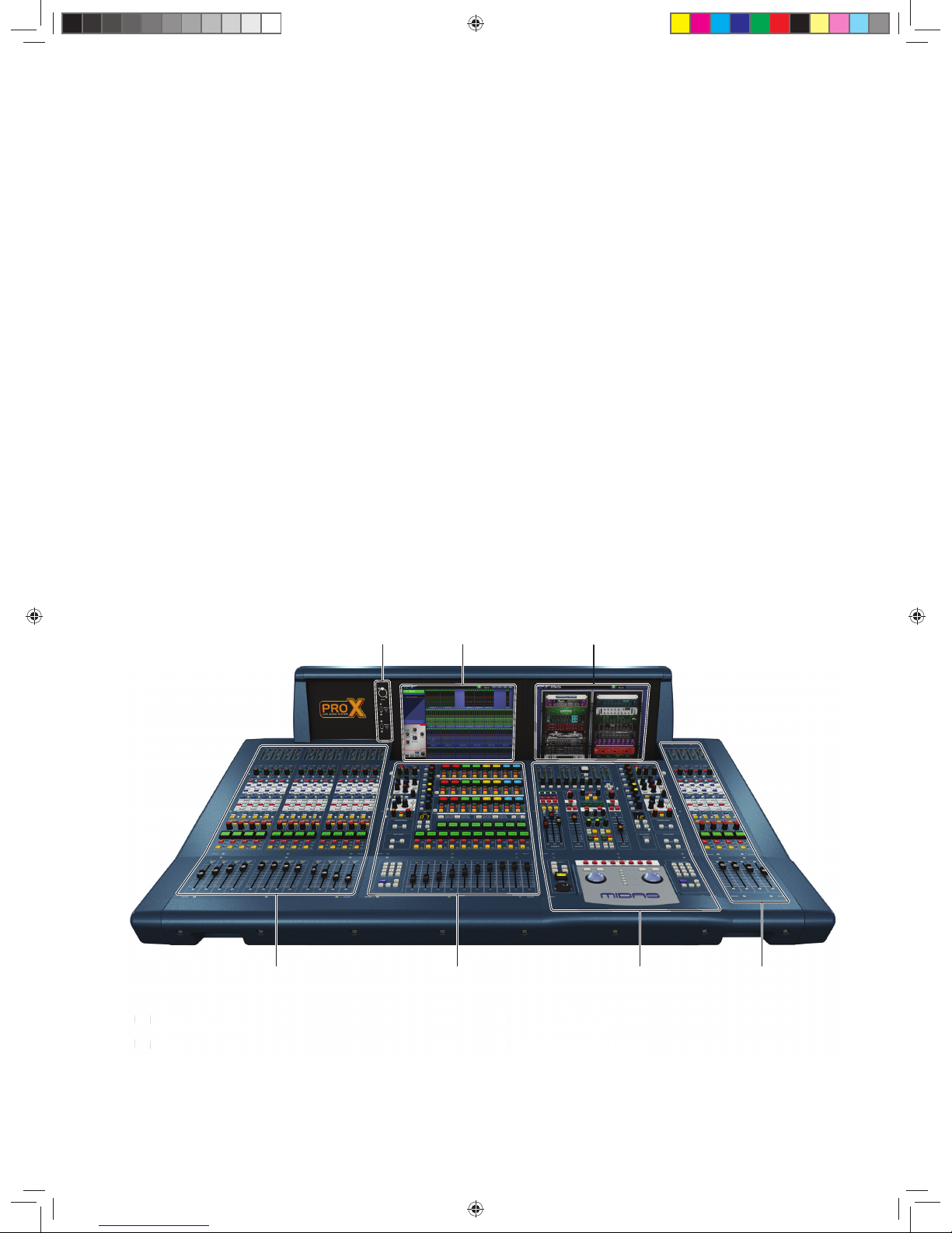
(1) Input bay (12-channel)
(2) Mix bay
(3) Master bay
(4) Input bay (4-channel)
(5) Mix bay GUI screen
(6) Master bay GUI screen
(7) Talk mic and USB connectors.
(1)
Input bay (12-channe
l)
(2)
Mix bay
(5) Mix bay GUI scree
n
(6)
Master bay GUI screen
(1)
(7) (5) (6)
(2) (3) (4)(1)
(7) (5) (6)
(2) (3) (4)
Page 13
13Quick Start Guide
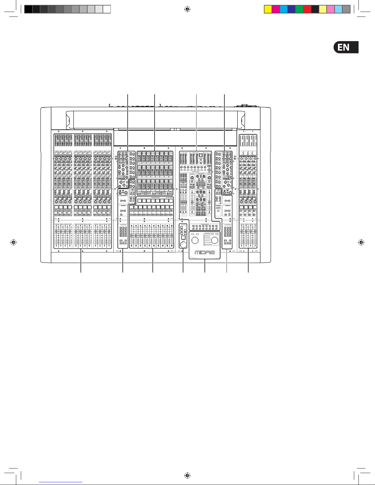
Control Surface
The control surface is divided into areas whose function is, largely, dependent on
bay location. Each bay has assorted control elements with local feedback and/or
support from the t wo centrally located GUI display screens. The screens can be
controlled remotely via external VGA connections, and third party systems can
also be viewed/controlled via an integrated KVM switch on the rear panel.
A — input fast zone: 16 input fast strips across the 12-channel and 4-channel
input bays provide the operator’s ‘must have now’ controls.
B — channel strip and mixes: processing areas, such as the D-zone (dynamic),
E-zone (EQ) and mix controls, provide a more comprehensive control by allowing
detailed adjustments to a single channel’s audio parameters.
C — channel and bus navigation zone: sections for channel and bus navigation
and selection. For details, see Navigation.
D — output fast zone: the new output-centric centre section, allows
the simultaneous display of 24 mono or stereo mix buses, and advanced
navigation buttons.
E — VCA and POP groups: VCA faders and POP group sec tions.
F — miscellaneous: master channel strips, A and B signal path monitoring,
communications, I-zone, surround monitoring and mute groups.
G — primary navigation zone: trackballs for mix and master bay GUI screen
control, and a screen access panel (bet ween trackballs) for direct access to GUI
menu options.
H — automation: scene store/recall and system edit.
ACEHGCA
BD F B
Page 14
14 PRO X
During show time the screen func tions that require fast access are controlled by
control knobs, pushbutton switches, faders, etc. More complex functions that do
not require this fast access are controlled by the trackballs and navigational keys.
A keyboard integral to the ight case is used for text entry via the master bay GUI
screen. An external USB keyboard can be used to operate the mix bay GUI screen.
The choice of controls provided by each bay t ype are prioritised by access time
importance. Fast zone areas, which contain fast strips, give instant access to
speci c functions across the bay, and channel strips give greater control of the
selected fast strip.
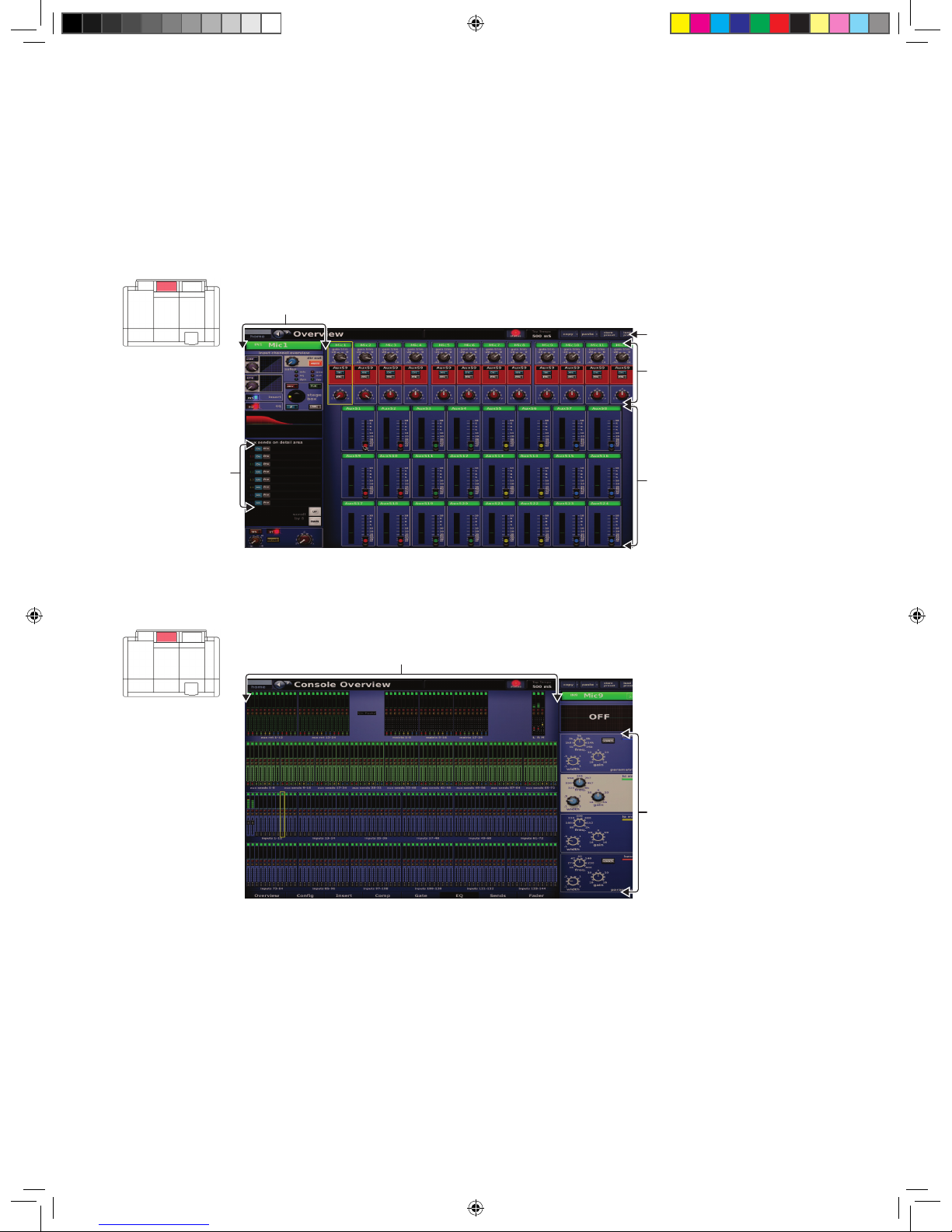
GUI
The GUI comprises two screens that provide a pictorial representation of the
control surface layout so that its displays are easy to follow at a glance. Not only
does it re ect what is happening on the control sur face, but it also provides
extra func tionality via a GUI menu. This menu provides access to all the screens
that you will require to set up, con gure, manage and operate the entire control
centre, all from a single drop-down list of easy to follow options.
Above: Typical Overview scre en (default of the mix bay GU I screen)
Above: Typical Meter s screen with no show loa ded (default of the mas ter bay GUI screen)
Channels strip
Banner
Inputs
Outputs
Channel type
select buttons
All meters
display
Inputs and automation
summary
Page 15
15Quick Start Guide
Each GUI screen has its own default display, although either is selectable via
the GUI main menu. The Overview screen displays 12 inputs and 24 outputs,
which are selected on the sur face. The Console Overview screen shows the
meters; both screens have a banner at the top, which is constantly displayed,
and a channel strip down the outermost side.
The channel strips have a similar func tion to the ones on the control surface,
but provide extra functionalit y. Each displays an overview of the associated
selected channel, which is divided into speci c sections that provide access to
processing areas.
Front And Rear Panel Connections
The control centre has connector panels on both the front and rear, and also to
the left of the mix bay GUI screen.
The connector panel to the lef t of the GUI has an XLR socket and two USB sockets
for connecting a talk mic and USB devices, respectively. For example, you can
connect a USB memory stick for show le backup and transfer, or a USB keyboard
for text editing on the GUI. The top USB socket is associated with the mix bay and
the bottom one with the master bay.
There are two panels at either end of the front of the control centre, under the
armrests. Each has a keyboard and phones socket. The lef t and right keyboard
sockets operate the mix and master bay GUI screens, respectively. The phones
socket in the left panel is for the monitor A section and the other one is for
monitor B.
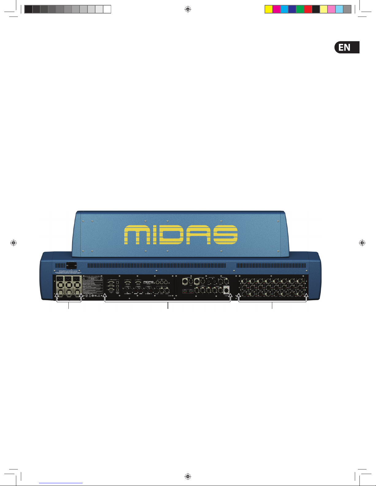
A connector panel on the rear of the control centre has three main sections
(see below). On the left are three mains power inlet and ventilation assemblies,
with a DC power switch above. The mid-section contains connections for the
audio, network, communications, intercoms, synchronisation, external remote
devices and peripheral devices. The section on the right is the user-con gurable
modular I/O section.
The modular I/O section can house up to three of any of the following I/O
modules in any combination: DL441 analogue input (mic) module; DL442
analogue output module; DL443 analogue Jack I/O module; DL444 8 analogue
mic in and 8 analogue line out module and DL452 AES/EBU input and output
module. This gives a maximum of 24 inputs and 24 outputs, if the appropriate
cards are tted.
Above: Rear view o f the Control Centre.
Mains power
and ventilation
Audio, control
and networking
I/O
(conguration dependent)
Page 16

16 PRO X
Basic Principles
Before You Start
This chapter is intended to familiarise you with the control centre by showing you
how to carry out some basic operations in order to get some audio out of it.
NOTE: As the operation of both input bays is principally the same, this
chapter will generally only show the operation of the 12-channel input
bay. However, any di erences in operation between the 4-channel and
12-channel input bays will be shown.
Please don’t forget that, although this system is a complex, high-tech piece of
equipment, it is very easy to use.
Principles Of Operation
Control centre operation is based on the concept of colour s and groups rather
than ‘layering’ or ‘paging’, which is the case with most digital consoles on the
market today.
With so many channels available it is far easier to remember them by their usercon gured individual/group colour and name rather than their channel number.
The control surface is populated with instantly recognisable controls that are
logically distributed in major sections, so that all the controls you need to access
most of the time are always on the control surface, while the remainder are only
one action away. You can display all I/O meters, both on the control surface and
the GUI, to give instant monitoring feedback.
Operating Modes
You can change certain aspects of control centre operation by assigning di erent
tasks to certain areas of the control surface. This section will explain the di erent
ways in which the control surface can operate.
Normal mode
During normal operation the 12-channel input bay is operated from the mix bay
controls and GUI screen, while the controls and GUI screen in the master bay
operate the 4-channel input bay. Both input bays operate in unison and are,
in e ec t, area A.
NOTE: The 12-channel input bay will always be area A, no matter which
operating mode you are using.
Using the 4-channel input bay as area B
You can assign the 4-channel input bay as area B, thus making both the
input bays independent from each other. This facilitates two-man operation
(see Two-Man Operation).
Controlling the mix buses in ip mode
Flip provides a more global approach to mix bus level control. Normally, you can
only use the level control knobs in the channel strips to adjust the signal level of
the aux/matrix mix buses going to the aux/matrix channels. However, by using
ip you have the option of controlling them f rom either the pan control knobs or
the faders in the input fas t strips.
In ip mode the lef t/right arrow buttons in the upper channel select section
scroll across the input fast strips.
>> To con gure the control centre for pan or fader ip
1. At the GUI, choose home > Preferences > General.
2. Depending on which option you require, click the option button of one of the
following in the Fader ip sec tion. When an option is selected, it will contain
a red circle:
•
• “Flip to Faders”
•
• “Flip to Pans”.
>> To ip mixes to input pan/fader control
With an output selected on the control surface, press FLIP. The button will
illuminate to show you are in ‘ ip’ mode. The currently selected mix bus in the
input fast strips will change to AuxS1 and, on the GUI, the background colour of
the pans and faders will change accordingly.
Also, the LCD select buttons in the input fast strips will display the current bus
mode, for example, “MONO AUX”.
Hints And Tips
•
• Check what is hidden - On the control centre, unlike on an analogue
control surface, some of the set tings and parameters will be hidden
from view. At various times during a mix we recommend that you
select and view unused parameters to make sure there are no hidden
surprises, for example, a reverb send left from a previous mix
•
• Check the Meters screen - It is a good idea to frequently
monitor the Meters screen (default display of the master bay GUI),
which provides at a glance an overview of the control centre’s status
and operation. It shows all the meters and the status condition of
faders and some switches, such as solos and mutes. However, some
things will still remain hidden.
Saving Your Work
We recommend that you save your work regularly while carr ying out the
procedures included in this guide. Not only is this good prac tise during normal
operation, but in this instance it may save you from losing some set-ups that
could prove useful later on. To do this, create a new show (see To Open The
Automation Screen), and then continue reading through the remainder of this
section, following the instructions caref ully. Save your work at convenient points
(see To Create A New Scene Using The Current Settings and To Save A
Show Or Create A New One From The Current Settings).
Saving a show versus storing a scene
It is important to understand the di erences between saving a show and storing
a scene.
•
• Storing a scene saves the current set tings of the system to the show
le. Scene data is never updated unless you manually store a scene.
The show le remains unsaved in R AM.
Although the state of the control centre is copied every ve seconds, it is not
stored in a scene. Instead, it is placed in the NVRAM (non-volatile random access
memory) of the control centre’s memory, which is a type of RAM that doesn’t lose
its data when the power goes o . If the control centre loses power accidentally,
these settings are loaded so that audio parameters are identical, thus avoiding
audio level jumps. When power is lost, the show le loaded (if any) will not
subsequently be restored, and any unsaved changes to it will be lost.
•
• Saving a show copies the show le onto the internal solid-state disk
of the control centre. This provides you with a ‘permanent ’ copy,
provided you shut down the system properly as detailed in the
following section.
Shutting down the control centre properly
When switching o the control centre, we recommend that you use the
shutdown option of the GUI menu (see To S witc h O The Control Centre).
By using shutdown, the cached copy of the show data, whic h is maintained by the
system, is automatically store d. Shutdown then uses the current show le, NVRAM
data and cache les to restore the control centre to exactly the same s tate as at
power down; even to the point of loading the unsaved show and placing you at the
correct scene, with non-s tored scene data at the control surface.
If you don’t use the Shutdown option the audio parameters are still restored,
but the show and show status (saved/unsaved) cannot be restored automatically.
You must manually reload the show, and any unsaved changes will be lost.
Page 17

17Quick Start Guide
Working With The Control Centre
Although many controls on the control centre are similar to their equivalent
analogue-type counterparts, some have been speci cally designed for the PRO
Series, particularly those for navigation and GUI operation. As you will probably
have had experience on analogue consoles, you will already be familiar with
most of the PRO X controls and their operation. Therefore, this chapter only deals
with the GUI controls that may be new to you.
The navigational controls, such as quick access but tons and scroll buttons, are
described in Navigation, and the ones speci cally for automation can be found
in Managing The Scenes.
About Channel Operation
During normal operation the task of controlling the input (12 channels), aux,
return, aux sends and matrix channels is allocated to the two bays on the lef t.
The two bays on the right control the input (4-channel) and master channels.
This task allocation applies similarly to the GUI screens. However, you can control
any channel from either GUI screen. This is done by navigating the channel to
the GUI channel strip via the GUI menu; control is also then available via the local
channel strip on the control sur face.
About GUI Operation
This section explains the basic procedures you can per form at the GUI screens.
In general, you will control and operate the GUI by combining the operations
described here.
Each trackball controls the movement of a pointer on its respective GUI screen.
The left trackball operates the mix bay GUI screen and the right one operates the
GUI screen in the master bay. Each trackball has t wo buttons, which have similar
functionality to the buttons on a PC/laptop mouse. The left button is used in click
and drag operations, while the right button is generally used for editing and ner
control operations.
Operating The GUI Screen Controls
This section shows you how to operate GUI screen elements, such as buttons,
control knobs, drop-down lists and sliders.
>> To switch a GUI button on/o
Click the button. If it has a status indicator, this will illuminate/extinguish to
show that it is on/o , respectively.
>> To adjust a GUI control knob or fader
Use a drag operation. Move the pointer up/down/left /right for adjustment.
>> To select an option from a drop-down list
Click the drop-down arrow. The drop-down list will unfold to display some or all
of its contents, depending on how many items it contains.
Do one of the following:
Click the option you require
If necessary, scroll the list (see “To scroll a drop-down list ” below) to display the
option, and then click it.
>> To scroll a drop-down list
With the drop-down list displayed, do one of the following:
Drag the scroll box
Click the scroll bar. The scroll box will ‘jump’ in the direc tion of the click to
another position in the scroll bar
Click an up/down scroll arrow. The scroll box will ‘jump’ in the direction of the
scroll arrow to another scroll bar position. Clicking a scroll arrow when the scroll
box is adjacent to it has no e ect.
Using The GUI Menu
You can open the GUI menu at either GUI screen, or you can go directly a GUI
menu screen by using a screen access but ton.
Throughout this guide, menu/submenu option selection sequences are shown in
the following format (for example, for choosing the general preferences screen):
home > Preferences > General
>> To open the GUI menu
Click home.
Page 18

18 PRO X
>> To select a GUI menu option
Click the menu option, for example, Monitors. The background of the menu
option will change to blue when it is ready for selec tion.
>> To open the submenu of a GUI menu option
Move the pointer over the arrow to the right of the desired menu option.
The submenu will open automatically to the right of the arrow.
>> To open a GUI menu screen using a screen access button
In the primary navigation zone, press a screen access button to open the
rst screen (printed to the right of the button). Press it again to open the
second screen.
Tex t Edi tin g
A keyboard is used to type in text on the GUI, for example, to con gure input
and output channel names. Editable tex t on the GUI is contained in text boxes,
which generally consist of a single line of limited length. Although all text editing
can be done using the normal keyboard func tions, the GUI can be used to assist
you, for example, by highlighting portions of text (using drag).
These tw o examples show you ho w to use the screen acc ess buttons to op en the Automation sc reen (single pres s) and the Graphic EQs sc reen (two presse s).
These but tons take you direc tly to the scree n you want.
>> To enter/edit text via the keyboard
At the GUI, click in the text box to place an inser tion point in it. The pointer will
change to an I-beam shape.
Using the keyboard, type in the new text. If the text box already contains some
text, you can delete this rst or edit it, which can be done via the keyboard or by
using the cut, copy and paste options after right-clicking.
Press ENTER on the keyboard to exit the text box (or click on an empty area of
the GUI screen). The pointer’s shape will change back to an arrow.
Page 19

19Quick Start Guide
Navigation
An Introduction To Navigation
The control centre provides you with unique navigational controls to quickly and
easily access the items, such as channels, buses, groups and processing areas,
that you will require for mixing.
Navigation is an important feature of the control centre. One of the advantages
digital consoles have over analogue ones is that their channel count is not
limited by the control surface hardware. However, this means that only a certain
amount of channels can be at the control surface at any time, while the others
are ‘hidden’. So, navigation is required to access these hidden channels whenever
you need them.
NOTE: The way the control centre is set to operate may alter the
function of some of the navigational controls. For more information,
see Operating Modes.
Navigation is primarily via the control sur face, although the GUI may provide an
alternative and also has some unique navigational features of its own.
Navigating The Input Channels
The input channels are grouped into ‘banks’, with each bank containing four
consecutively numbered channels.
During normal operation, four banks of input channels populate the input bays,
and these are displayed across the control surface in ascending order from
left to right.
Page 20

20 PRO X
Input channel navigation controls on the PRO X.
7
9
5
6
8
1
Mix bay channel strip
Input fast
strip
3
2
4
Item Element(s) Description
1
Quick access but ton —
channel str ip
Quickly sele cts the local proce ssing area of the selected c hannel or channel pair, but doesn’t a ect channel se lection.
Illuminates (blue) when active.
2
Quick access but ton — input
fast strip
Quickly sel ects the local input c hannel and assigns the local pr ocessing area to the mix bay channe l strip.
Illuminates (blue) when active.
3
LCD select bu tton — input
fast strip
Select s the local input channel. Has a back lit LCD display (with user-con gurable backlight colour), which shows cha nnel name etc.
When selec ted, the display changes to a ‘negative ’ image.
4
LCD select bu tton — VCA/
POP group
Select s the VCA/POP group, unfoldin g the group members to the contr ol surface. Has a backlit LCD display (wit h user-con gurab le
backlight colou r), which shows group name. Wh en selected, the display chang es to a ‘negative’ image.
This butto n is also used for settin g up the group (see To Assign Chann els to a VCA/POP Gro up).
5
Channel sele ct keys and
button
The INPUT button in the channel type secti on is used with the number keys in t he lower channel select se ction to select a spe ci c
channel number, assigning i t to the control surface (see Fault Fin ding A Problem Chan nel).
6 ALIGN button
Navigates the cur rently selected input c hannel to the local input bay (see To Navigate T he Selected Input Ch annel Back To
The Control Su rface”).
7 scroll by 4 / 12 buttons
These lef t and right scroll but tons scroll through the inpu t channels 12 channels at a time on the lef t 12-channel bay, and 4 at a time
on the right 4 -channel bay
8 B button Assigns the 4 -channel input bay as area B, wh ich then operates with the m aster bay channel strip.
9 scroll by 1 bu ttons These lef t and right scroll butt ons scroll through the channe ls one at a time. Channel selecti on follows the scrolling.
Page 21

21Quick Start Guide
>> To assign an input channel to the control sur face
Do one of the following:
•
• Scroll buttons - Scroll the desired input channel to the control
surface using the scroll by 1 / 12 buttons in the input select section.
•
• VCA/POP group buttons - If the desired input channel is in a group,
press its VCA/POP group LCD select button.
You can use the GUI menu to select any VCA/POP group you want via the
home > Control Groups > VCA Groups option.
>> To select an input c hannel
With the desired input channel currently assigned to the input fast strips on the
control surface, do one of the following:
•
• LCD select but ton - Press the LCD select button in the desired input
fast strip. This will assign the input channel to the local channel strip
and its input channel overview to the GUI channel strip
•
• Quick access button - Press any quick access button in the desired
input fast strip. This will assign the input channel to the local channel
strip and its local processing area to the GUI channel strip.
You can use the scroll by 1 buttons in the upper channel select section to
scroll channel by channel to go to the input channel you want. You can scroll all
of the input channels using this method and the desired input channel doesn’t
have to be assigned to the control surface initially. Channel selection follows
the scrolling.
You can use the GUI menu to select any input channel you want via the
home > Input Channels option.
>> To navigate the selected input channel back to the control surface
If you have navigated the currently selec ted input channel away from the control
surface, you can bring it back by pressing ALIGN.
>> To select a processing area
You may want a speci c processing area of an input channel assigned to the local
channel strip, for example, to carr y out processing or for copying its parameters
to another input channel.
Do one of the following:
•
• Quick access button (channel strip) - If the input channel you
want is currently selected at the control surface, press the quick access
button local to the desired processing area in the channel strip
•
• Quick access but ton (input fast strip) - If the input channel you
want is currently at the control sur face, but is unselected, press
the quick access button local to the desired processing area in its
input fast strip.
You can select a processing area via the input channel overview in the GUI
channel strip by clicking within a non-control area of the desired sec tion.
Page 22

22 PRO X
Navigating The Mix Buses
The input channels each have aux and matrix mix buses.
Mix sections
(mix bay)
Mix sections
(master bay)
Input fast
strip
1
6
5
43
2
43
2
5
Item Element(s) Description
1
Quick access but ton — input
fast strip
This butto n in the mix section of the input f ast strips quickly s elects the local mi x area of the selected ch annel.
Illuminates (blue) when active.
2
Quick access but ton — mix
selection
This butto n in the mix section of the mix and ma ster bays quickly selec ts the bank of the current ly selected aux/matr ix
bus, assigning it to th e local channel strip on the con trol surface, and also assignin g the bus processing area to the loc al GUI
channel strip.
Illuminates (blue) when active.
3 scroll by 8 bu ttons These up and dow n scroll buttons scr oll through the mix buses in g roups of eight (one bank) at a time.
4 scroll by 1 bu ttons These up and dow n scroll buttons scrol l through the mix buses one at a ti me. Mix bus selection foll ows the scrolling.
5 Display Shows the number of t he currently selec ted mix bus and its type.
6 FLIP butt on See Contro lling The Mix Buses In Flip Mod e.
Page 23

23Quick Start Guide
>> To navigate a mix bus to the control surface
Do one of the following:
•
• Scroll to the desired mix bus using the scroll by 1 buttons in the mix
section. Mix bus selection follows the scrolling
•
• Scroll the desired bank of mix buses to the control surface using the
scroll by 8 but tons in the mix section
•
• Select the desired mix bus in the Output Bay and press Align.
>> To select a mix bus
Do one of the following:
•
• Scroll buttons - Scroll to the desired mix bus using the scroll by 1
buttons in the mix section. Mix bus selection follows the scrolling
•
• Touch sensitive control knobs - With the desired mix bus
assigned to the mix section on the control sur face, touch/operate its
control knob.
>> To navigate the mix bus processing area to the channel strip
Press the quick access button in the mix section of the desired input fast strip.
This does not a ect the current population of the output fast zone.
You can select an aux bus or matrix bus processing area on the GUI by clicking
on the title of the desired bank of mix buses in the input channel overview of
the GUI channel strip (see Typical Sends Sections Of The Mixes In The Gui
Channel Strip).
Page 24

24 PRO X
Navigating The Output Channels
The output channels comprise auxes, matrices and masters.
Master channels
8
6
7
1
2
4
3
5
Master bay channel strip
9
Item Element(s) Description
1
Quick access but ton —
master channels
Quickly sele cts the local master chan nel. Illuminates (blue) when active.
2 To Faders Moves the curre ntly-selected group to th e faders below.
3 LCD select but ton Select s the channel. Has a backlit LCD display (with use r-con gurable backlight colou r), which shows group name.
4 Mute button Mutes the selec ted channel.
5 Solo butto n Solos the sele cted channel.
6
Channel sele ction keys
and button s
The button s in the channel type section (except th e INPUT button) are used with the nu mber keys in the channel select (lower)
section to s elect a speci c output channel number, assigning it to th e control surface (see Fault Find ing A Problem Chann el.
7 scroll by 1 bu ttons These lef t and right scroll butt ons scroll through the channe ls one at a time. Channel selecti on follows the scrolling.
8 scroll by 24 buttons These lef t and right scroll butt ons scroll through the channe ls 24 at a time. Channel sele ction follows the scro lling.
9
Quick access but ton —
channel str ip
Quickly sele cts the local proce ssing area of the selected c hannel or channel pair, but doesn’t a ect channel se lection.
Illuminates (blue) when active.
Page 25

25Quick Start Guide
>> To assign output channels to the control sur face
Do one of the following:
•
• Channel type buttons - On the PRO X the Channel Type buttons
have been replaced with 24 Out LCDs which are assignable in the
usual manner: press and hold, and then selec t the channels you wish
to assign.
•
• Scroll but tons - Scroll the desired output channel to the control
surface using the scroll by 1 buttons in the channel select
(upp er) se ctio n.
To select the desired output group, scroll through the input fast zone with the
Scroll by 24 buttons.
>> To select a processing area
You may want a speci c processing area of an output channel assigned to
the local channel strip, for example, to carry out processing or for copying its
parameters to another output channel. To do this, provided the output channel
is currently selected at the control surface, press the quick access button local to
the desired channel strip’s processing area to selec t it.
You can select a processing area via the GUI by clicking on a non-control area
within the desired section of the ‘overview’ display (aux send, aux return,
matrix or master) in the GUI channel strip.
Navigation Via The GUI
The GUI has unique navigational tools by which to return to a channel ‘overview ’
display from one of its processing areas in the GUI channel strip, and also to
browse through the GUI screen display history.
>> To navigate back to a channel’s overview display from one of its
processing areas in the GUI channel strip
Click the return arrow in the channel header.
>> To nd a GUI screen that you recently opened
Use the back/for ward browser buttons to do one of the following:
To return to the GUI screen you have just opened, click the back button
To open one of the GUI screens you have recently visited, click the back/forward
buttons. The back but ton will take you back through your browser history,
while the forward but ton goes the opposite way.
The back/for ward buttons are similar to those on standard browsers used
on any PC.
Fault Finding A Problem Channel
If you know the number of the channel that has a problem, you can quickly
navigate it to the control surface by t yping in its channel type and number via
the lower channel select (lower) and channel type sections.
>> To select a channel using its number
1. In the channel type sec tion, press the button of the desired type.
For example, if the channel is an input, press INPUT.
2. In the channel select (lower) section, type in the channel’s number.
For example, press 4 and then 7 for channel 47.
3. Press ENTER.
Con guring The Inputs And Outputs
Similarly to the VCA/POP groups, you can change the name and colour of each of
the inputs and outputs. This is done via the GUI at their respective sheet screens.
For con guration details, see Con guring VCA/POP Groups.
>> To open the Input/Output Sheet screen
Do one of the following:
•
• At the GUI, choose home > Input Channels > Input Sheet to open
the Input Sheet screen, or choose home > Mix & Outputs > Output
Sheet to open the Output Sheet screen
•
• In the primary navigation zone, press the inputs/outputs screen
access button to open the Input Sheet screen. To open the Output
Sheet screen, press it again.
Page 26

26 PRO X
Patching
Introduction
Patching is a GUI-only feature that lets you carry out all system routing
requirements. The GUI main menu has a Patching option that takes you to the
Patching screen, which contains all of the available patching connectors in
the system. This screen provides an easy-to-use interface, where you can select
your source and destination patching options, facilitated by a panel of func tion
buttons. Additionally, the Patching screen lets you set up the units (devices).
For example, you can adjust the analogue gain, selec t +48 V phantom voltage
etc., of the line I/O units connected in the system.
Item Element(s) Description
1 SINGLE button Lets you patch a sing le source to a single destination or mu ltiple destinations. See Single Patching (SINGLE).
2 SEQ. button Lets you select m ultiple sources and patch the m one by one. See Sequence Patching (SEQ.).
3 AUTO button
Lets you selec t a block of sources and patch the m all automatically, simply by selecting a si ngle destination. Any exist ing patches
within the des tination range will be repla ced by the new ones.
4 NONE button Clears all cur rently selected patch con nectors from all tabs i n the From and To sections.
5 LIST button Chan ges the tooltip type fr om standard to list when carr ying out a sequence patchin g operating via the SEQ. but ton.
6 CHECKPOINT button
Sets a patchin g store point, or snapshot, that contain s the patching status at that inst ant. Each time CHECKPOINT is clicked th e
previous checkpoint is overwritten.
7 RESTORE button
Reverts p atching status to the last che ckpoint or, if no checkpoint s have been created, it will rever t patching status to the power up
condition. All patc hing done in the intervening per iod will be lost.
8 UNDO button
Undoes the lates t single patch, even if it was part o f a multiple patching operatio n. Repeated clicks will undo th e preceding
patching opera tions, going back to the last che ckpoint, or power up if no check points have been created.
Page 27

27Quick Start Guide
Item Element(s) Description
9 REDO button Redoes an undo. This can be repe ated for each undo in the previou s undo operation.
10 CLEAR SEL. butto n
Clears all cur rent selections and t heir patches.
Important:
Unlike the NONE but ton, which merely removes the cur rent selections (highli ghted in yellow), CLEAR SEL. goes a step furt her by
removing the patc h as well. This will stop any audio that may have bee n going through the patched sign al.
11 C LE AR b utt on
Clears all patc hing.
Important:
Exercise gr eat caution when using this f unction. Observe t he warning that appears af ter clicking this but ton.
12 CO NFIG but ton
Opens the AES50 De vice Con guratio n window, from where you can set up the I/O t abs in the Patching screen (see Typic al AES50
Device Con guration window).
13
STORE PRESET and LOAD
PRESET buttons
These are user li brary (preset) func tion buttons. See Use r Library (Presets).
14 Title section Section titles and tab names.
15 Patching area Contains all of the patch connec tors on tabs.
16 To section Houses the tab s that contain all of the patch connec tor destinations.
17 From sectio n H ouses the tabs that contain all of the p atch connector sources.
>> To access the Patching screen
Do one of the following:
•
• At the GUI, choose home > Patching
•
• Press the patching/metering button in the primary navigation zone
•
• At the GUI, click a src (source) or dest (destination) button.
The Patching screen will open at the appropriate tab/
con guration window.
About The Patching Procedure
Although patching can be thought of as routing/rerouting the control centre’s
incoming, internal and outgoing signals, in the context of the Patc hing screen,
patching also encompasses the set ting up and con guration of the stage and
FOH rack I/O devices. The patching procedure is initially carried out after system
installation and comprises:
•
• Device con guration - Con gure the devices by adjusting their
parameters (see below)
•
• Setting up the I/O rack devices - Set up the system devices, such
as line I/O, DN9696 and generic AES50, in the I/O tabs in the From
and To sections of the Patching screen (see Setting Up The I/O
Rack Devices)
•
• Patching - Carry out all of the required routing, for example, mics to
input channels (see How To Patch)
•
• Snake selection - Con gure the control centre according to the type
of ‘snake’ you are using for the X and Y networks (see Con guring
The Snake Type). This is impor tant, as the control centre will
not work unless the snake type is correctly con gured.
Con guring The Snake Type
Important:
The snakes must be correctly con gured before operating the control
centre, as it will not pass audio or control data if the snakes are not
con gured correctly.
You can connect the Neutron DSP Engine to the control centre with either
copper or bre-optic snakes. The control centre needs to be con gured with this
information before operation can begin.
>> To con gure the control centre with the snake type information
1. At the GUI, choose home > Preferences > General.
2. Under the Stage Link X heading, click the Fibr e or Copper option,
according to whichever is t ted to the X network. A selected option will
contain a red circle.
Do the same for the Y network, under the Stage Link Y heading..
Setting Up The I/O Rack Devices
You can add, remove and set up the devices, such as line I/Os, mic splitters,
DN9696s etc., that are in the Stage I/O and FOH I/O racks. This is done via the
AES50 Device Con guration window. Here, you can set up the device ID and
also the type of cards (modules) tted to the physical unit. The options are
context-sensitive, so some may be blank, depending on the type of device.
To cater for the dual redundant ports of the Mic Splitter and Modular I/O (X and
Y connections) there are several options in the device type: drop-down list,
for example DL431 Cable Red, DL155 Cable Red, etc. Initially, the device is
allocated to a port (as for any device), then a second port is allocated to the
redundant connection, but with the same device ID (see below for details).
Page 28

28 PRO X
Item Descript ion
1 List of Stage and FOH p orts, showing current de vice assignments.
2 device type drop-down li st, contains a list of the available device s to choose from.
3 device ID drop-down list, co ntains a full list of IDs for the sele cted device type. Thos e already in use will be pre xed with the text “( In use)”.
4
device options drop-down lis t(s), from which you can se lect the card that is ac tually tted in the physic al unit. The positions of the dro p-down lists are relati ve to
the card posit ions in the physical unit.
5 CLOSE button, clos es the AES50 Device Con guration window.
>> To add a device or change its set up
1. Click CONFIG to open the AES50 Device Con guration window.
2. Click the por t to which you want to allocate the device. For example,
“FOH Port 3 (unused)”. The text in the device type: eld will change
accordingly. (A port that has no device allocated to it will have the tex t
“(unused)” after its name.)
3. In the device type: drop-down list, click the type of device.
For example, “DL351A”.
4. In the device ID: drop-down list, click the ID you want for the device.
For example, “ID6”.
5. In the device options: drop-down list, click the type of card tted physical
unit. For example, “Analogue 8 Input”. If there is more than one device
options: drop-down list, repeat for the remaining ones, making sure they
match the actual cards tted (DL351 & DL451 only).
6. Click CLOSE.
Con guring The Devices
You have the option to con gure the devices from the Patching screen.
Parameters, such as gain and +48 V phantom voltage, can be adjusted or
switched on/o , respectively, via a device-speci c con guration window.
These con guration settings can be independent of channel data,
as (until patched) they only control the physical unit. If a device is subsequently
patched to one or more channels, the channel(s) control the device,
and vice-versa.
The device con guration area also allows control of audio parameters when the
device is used as a direct connec tion to another device. For example, FOH to stage
via a digital snake, instead of through the DSP. In this case the settings are also
saved in the show le and c an be automated, even though the signals are not
routed through the control centre DSP.
Device con guration procedure
Although the procedure for con guring the devices is similar, their parameters
are dependent on device type. The procedure for con guring the devices of a
similar type involves:
•
• Opening the con guration window of the device
•
• Selecting one of the device’s cards/channel ranges and con guring
the available parameters
•
• Repeating for the other cards/channel ranges of the device
•
• Repeating for the other devices
•
• Closing the device’s con guration window.
>> To open the con guration window of a device
Click the device’s spanner button.
>> To set up/change the con guration of an I/O device
1. Open the con guration window of the I/O device you want to con gure.
2. Select the I/O device from the drop-down list at the top of the
con guration window.
Page 29

29Quick Start Guide
3. Select the card/channel you want to con gure/change, from the drop-down
list at the upper-right corner of the con guration window. For example,
the “Analogue In Card”.
4. In a channel, con gure the parameters. For example, in channel “In1”,
adjust the gain and switch the +48V phantom voltage on.
5. Repeat step 4 for the other channels in the card.
6. Repeat step 3 to step 5 for the other cards.
7. If necessary, con gure other I/O devices by repeating step 2 to step 6.
8. Click CLOSE.
How To Patch
Patching, basically, involves selecting the source patching connectors in the
From section of the Patching screen and then selecting their destination(s)
in the To sec tion. You can select patches singly, or in multiples by using the
sequence and automatic operations.
>> To open a tab in the From or To sections
Click the tab title. For example, click Ins. Sends to open the insert sends tab.
>> To select a single patch connector
Click the patch connector. The e ects of clicking a patch connector are shown in
the following table.
Clicki ng Does thi s in the From sec tion Does thi s in the To section
Select s the patch connector.
Will do one of the follow ing (provided a source patch connec tor(s)
has been selec ted in the From sectio n):
•
Selec ts the patch connector dur ing a single patching operation.
• Patches the patch conne ctor during either a sequ ence or an
automatic patching operation.
Otherwi se, this has no e ect.
Deselec ts the patch connector, which the n reverts to its
previous state (patched or unpatched).
or
Removes the patch.
Select s the patch connector and all th e ones it is patched to in
the To section.
Removes the patch.
NOTE: To quickly check the destinations of a source patch connector, click it. This will select it and all of its destinations. A green triangle will appear under the
name of any tab in the To section that contains a destination(s).
Page 30

30 PRO X
Single Patching (SINGLE)
The SINGLE function button lets you patch a single source to a single destination
or multiple destinations.
>> To patch a single source to a single destination
The following example shows you how to patch an output from a mic split ter to an
input channel.
1. Click SINGLE.
2. Select the source patch connector. For example, in the Stage I/O tab of the
From section, click the rst patch connector (XLR1) of card A of the DL351
Modular I/O. Its background will change to yellow and a green triangle will
appear under the tab title (as shown right).
3. Select the destination patch connector. For example, in the Inputs tab of the
To section, click the patch connector for input channel 14 (Mic14). It will now
be patched to the source. If the new patch is carrying a signal, this audio may
be heard, depending on the settings of the control centre.
NOTE: You can also carry out single patching operations using the
CLEAR SEL. and AUTO functions.
>> To patch a single source to multiple destinations
Patch the desired source patch connec tor to one of its destinations, as detailed in
To Patch A Single Source To A Single Destination.
In the To sec tion, select the other destinations.
Sequence patching (SEQ.)
If you need to do a number of patches, and each has only a single destination,
you can use the sequence func tion. All of the source patch connectors are selected
in the From section before being patched, one by one, in the To section. This saves
you having to go back to the Fro m section at the start of each patch.
To assist you in sequence patching, you can change the tooltip to the lis t type
(see the LIST function button in the Patching Screen diagram).
Page 31

31Quick Start Guide
Basic Operation
This section is intended to familiarise you with the control centre by showing you
how to carry out some basic operations in order to get some audio out of it.
NOTE: As the operation of both input bays is principally the same,
this chapter will generally only show the operation of the 12-channel input
bay. However, any di erences in operation between the 4-channel and
12-channel input bays will be highlighted.
Setting A Mic Ampli er’s Input Gain
The control centre has two input gains per channel, one is the remote gain for the
analogue mic pre (stage box gain) and the other is the digital trim (console gain).
In its default state, the stage box gain is in the channel strip and the console gain
is in each input fast strip. However, you can swap these sections over (by pressing
the gain swap button) to give you a more global control of the stage box gain.
NOTE: The gain trim and stage box control knobs on the control surface
will adjust whatever has been ‘swapped’ to their respective strips and
not necessarily what their names suggest. The stage box control knob
(channel strip) always controls the alternative ‘swap’ to the ones shown in
the input fast strips on the GUI screen.
>> To set the stage box gain/console gain
1. In the gain trim section of an input fast strip, press the quick access button
(see Gain and lter sections of the input strips). This selects the input
channel and assigns its con guration processing area to GUI channel strip,
which contains the GAIN SWAP button.
2. Press the lef t-right arrow gain swap but ton (or click GAIN SWAP) to swap
the gain trim and stage box sections over.
3. Adjust the gain trim control knob to the required level to suit the MIDAS
pre-amp characteristic. A suitable level could be one that only just
illuminates the yellow LEDs. Do this for each required channel. Drive the mic
amps for that ‘MIDAS colouration’; feel free to overdrive if you want.
4. After you have achieved the required gain state, press the lef t-right arrow
gain swap button (or click GAIN SWAP) to swap the gains back to their
default state.
5. Adjust the gain trim control knob to (this time) adjust the console digital
trim (+20 dB to -40 dB continuous trim) for your preferred gain structure.
6. Set analogue remotes for initial set-up, then adjust digital trim
for showtime.
Setting The High And Low Pass Filters
Select high and low pass lters. The high and low pass lters can be switched
on/o and, when on, each has two settings. The lters are replicated on the GUI,
which also shows the value of the lter in operation.
>> To set both high and low pass lters in
1. In the gain trim section of an input fast strip (see the Gain And Filter
Sections O f The Input Strips diagram), press the quick access button.
This selects the input channel and assigns its con guration processing area
to the GUI channel strip, which contains the l t e r s section.
2. In the lters section of the input channel strip, press the lter select button
(high pass or low pass) to switch the lter in.
3. If necessar y, press the lter’s SLOPE button to set its slope (dB); its status
is shown on the GUI. For the high pass lter, in = 24 dB and out = 12 dB,
and for the low pass lter, in = 12 dB and out = 6 dB.
4. Adjust the high pass/low pass control knob to set the lter frequency (Hz).
The ranges are 10 Hz to 400 Hz for the high pass lter and 2 kHz to 40 kHz for
the low pass lter.
Page 32

32 PRO X
Input Equalisation (E Zone)
Use EQ to equalise the input signal via the treble, hi-mid, lo-mid and bass lters,
which are situated in the input channel strip’s E zone. Treble and bass each have
a parametric lter option and three speci c shelving modes. Visual feedback for
EQ is via GUI only.
>> To EQ the input signal
1. In an input fast strip, press the quick access but ton of the desired EQ lter
(treble, hi-mid, lo-mid or bass). This will select the channel and open the
EQ lter’s processing area in the GUI’s channel strip. Alternatively, you can
navigate to it using the bass and treble up and down arrow but tons in the
E-zone (shown above).
2. In the input fast strip, press EQ to switch the EQ in. The EQ button’s LED will
illuminate when its EQ is switched in.
3. In the E zone, adjust the freq, width and gain control knobs to apply
EQ as desired.
4. Audition the di erent lters, including the ‘minimum harmonic disruption’
types, by scrolling through them using the SHAPE button.
NOTE: The minimum harmonic disruption lter s are bright and deep,
which are available for treble and bass, respec tively. These lter s use
psychoacoustic phenomena to generate steep slopes that sound natural.
Graph shows the eects of EQ
LEDs for EQ
lter selection
indication
Filter quick
access button
Input fast strip
GUI channel strip
E zone
Page 33

33Quick Start Guide
Input Dynamics Processing (D Zone)
Set up compressor and gate dynamics processors using the controls in the input
channel strip’s D zone.
There are four compressors available, correc tive, adaptive, creative and vintage,
each with the option of hard knee, medium knee and soft knee.
>> To set up a compressor/limiter
1. In an input fast strip, press the compressor quick access button in the comp
section. This will select the channel and assign its compressor processing
area to the GUI channel strip.
2. In the comp section, press ON to switch the compressor in.
3. In the D zone, operate the attack, ratio/range (rat io), release, threshold
and make up controls to apply processing. You could also set up a limiter by
using a high threshold and a steep ratio (greater than 5:1). The hold control
knob has no a ec t as it is only used for the gate.
4. Press KNEE to audition the di erent algorithms.
5. Press MODE to try di erent compressor types (corrective, adaptive,
creative, shimmer and vintage).
>> To set up a gate
1. In an input fast strip, press the gate quick access button in the gate section.
This will select the channel and assign its gate processing area to the GUI
channel strip.
2. In the gate section, press ON to switch the gate in.
3. In the D zone, operate the attack, ratio/range (rang e), release,
threshold and hold controls to apply processing. The make up control
knob has no a ec t as it is only used for the compressor
4. There is also a MODE func tion to select either Gate, Transient Gate or
Ducker modes.
Output Processing
The outputs have a six-band PEQ with shelving modes on bands 1, 2 and 6.
They also have the option of using a GEQ, which is accessed via the GEQ button in
their EQ processing areas.
Using VCA/POP Groups
VCA/POP groups (bottom of the mix bay) allow simultaneous control over a
number of channels. This provides a quick method of bringing particular channels
to the control surface and saves you having to remember their name/number.
You can choose channel group associations and also con gure the colour and
legend of each group’s LCD select button to make them instantly recognisable.
The LCD select button for each group is used for both group member assignment
and group recall.
Any group can have any channels (input/output) assigned to them, although in
normal practise is more likely that they will only have one or the other.
VCA groups include fader, solo and mute control. However, POP groups — which
have no audio function — are limited to unfolding channels (on area A or B).
POP groups let you create a group of related instruments that you need on the
control surface for some function.
Page 34

34 PRO X
>> To assign channels to a VCA /POP group
1. Press and hold down the LCD select button of the desired group (VCA or
POP). For example, “Kit” in the VCAs (as shown above). The group’s LCD
select button will start ashing when you are in group member selection
mode and the inputs will jump to program mode.
2. While still holding down the LCD select button, do one of the following:
•
• To assign an input channel to the group, press the LCD select button
of the desired input channel. Repeat for any other input channels you
want in the group. For example, “Kik 1”, “Sn1”, “Hihat” and “Tom”
(shown above). If necessary, scroll to a new bank of input channels
•
• To assign an output channel to the group, press the LCD Select button
of the desired output channel. Repeat for any other output channels
you want in the group. If necessary, navigate the desired output
channels to the control surface. The LCD Selec t button of any output
channels that are at the control surface and are group members will
illuminate. Individual output select buttons will ash if their bank
contains a member of the current group.
3. Release the group LCD select button. The group now contains the channel
members you have just assigned and the group will be selected.
4. To exit the group, quickly press the group LCD select button.
Con guring VCA/POP groups
The default name and associated colour of a group, which appear on its LCD
select button and on the GUI, can be con gured to suit your own preference.
You can also globally change the colour of the group members to match the
group colour.
Con guration is carried out at the Group Sheet screen.
NOTE: Clicking the control knob icon will take you to the VCA Groups
screen (a submenu of the Control Groups option), which provides group
management control.
>> To access the Group Sheet screen
Do one of the following:
•
• At the GUI, choose home > Control Groups > Group Sheet
•
• In the primary navigation zone, press the vc a/assignable controls
screen access button.
>> To set up the name of a VCA/POP group
Do one of the following:
•
• Choose from a list of pre-con gured names by clicking the pencil
icon of the group. In the drop-down list, click the name of your choice,
for example, “E Gtr”. Scroll the list, if required
•
• Type in a new name by clicking within the name eld of the group.
The pointer will change to a white ashing I-shaped cursor, which
will appear at the end of the name eld. Type in the new name via the
keyboard (maximum six characters).
>> To set up the colour of a VCA /POP group
1. Click the palette icon of the group.
2. In the palette, click your chosen colour.
>> To set up the colour of a VCA /POP group and all of its members
Click the ll icon of the group. The colour of all group members will now match
that of the group.
Setting Up A Mix
The control centre has 96 con gurable mix buses (72 auxes and 24 matrices);
the auxes can be set to mixes, subgroups or mix minus. All of the mixes can
also be set up as stereo pairs or mono. 24 matrix outputs can also be accessed
directly from input channels via level controls, which gives the control centre the
ability to provide 32 discrete mixes, plus left, right and mono. The mix sections
(input fast strips) and the mix and sends sections (mix and master bays)
provide mix control and navigation, while the bus mode selection is via GUI only.
Similarly to the inputs and groups, identi cation of mixes is by colour coding.
The overview displays in the GUI channel strip (see below) show the status of the
mixes, which are colour coordinated to match those in the sends section of the
control surface.
Page 35

35Quick Start Guide
>> To select the mix bus mode
1. Select the mix bus (see To Select A Mix Bus).
2. Press the quick access button (adjacent to the lters section) to assign the mix
overview to the channel str ip. For example, the aux send overview for AuxS1.
3. Click a non-control area within one of the sections (for example, dir in)
to open the con guration processing area in the GUI channel strip.
4. Click MODE repeatedly to scroll through the mix modes (mix, group and
mix minus) to select the one you want. Group mode is fader only with no
pre-fader, and in mix minus mode all buses are initially routed — you have
to turn a bus routing switch on to take it out of the mix. Stereo mix mode
— with mix selected and LINK button on — is only accessed f rom the odd
numbered output channel of the linked pair. In stereo mix mode the top
control knob becomes pan adjust and the bottom one adjusts level. When
creating a stereo mix, you can use either the odd or even output to link the
two channels, but the mode of the odd channel is used on both.
>> To set up a mono aux mix
1. Making sure that the mix bus is not linked, select mix (see To Select The
Mix Bus Mode).
2. Select the input channel (see To Select An Input Channel).
3. At the GUI, click within the appropriate sends section (aux or matrices) in the
overview display to open its processing area.
4. In the mix (upper) section, do the following:
•
• Press PRE to select pre-fader (on) or post-fader (o ).
•
• Press ON to route the aux mix from input to aux output
•
• Adjust the level control knob to change the signal level.
You have the option to adjust them using the pan/fader controls in the input fast
zone (12-channel input bay); this is known as “ ip” mode. (You can also adjust
them in the GUI channel strip — overview or processing area — using drag.)
Page 36

36 PRO X
Mix bus routing
You can route an aux or matrix (or even master output) to an e ect or output.
This is a GUI-only operation, which is done via the GUI channel strip or Patching
screen (see Patching).
>> To route an aux or matrix to an e ect or output
Do one of the following:
•
• In the processing area of the channel strip, click the required mix bus
destination from the drop-down list. For details of how to open the
processing area, refer to To Select The Mix Bus Mode
•
• In the processing area of the channel strip, click dest. This will open
the Patching screen and the appropriate tab. For details of how to
open the processing area, refer to To Select The Mix Bus Mode
•
• Open the Patching screen and route the aux/matrix from there.
For information on patching, see Patching.
Linking
You can link two mixes together. Pairs can only be created from adjacent mix
buses of the same colour. To link a pair of mix buses, click the LINK button of
either of the mix buses (odd or even) you want to link (see To Select The Mix
Bus Mode).
The linked parameters default to the user-con gurable global default link
settings, which are set via the GUI menu (choose home > Preferences >
Linking). However, you can override these default link settings for the pair
via the Stereo Linking Options window, which is opened by pressing the
LINK OPT. button (to the right of the LINK button).
Using Fader Flip
For information on using fader ip, see Controlling The Mix Buses In
Flip Mode.
NOTE: When using fader ip to control the aux bus levels, always use the
GUI to check the level. This is because the fader level markings have a
maximum of +10 dB, whereas the aux bus levels only go up to +6 dB.
Setting up the e ects rack
The GUI’s E ects screen contains a vir tual 24-unit rack. You can have a maximum
of 24 e ects units in the rack, the number being dependent on con guration (via
the E ects and GEQs sec tion of the Preferences screen).
Each unit can contain any combination of the e ects listed in the
Change Device Type window.
The assignable controls panel is common to all e ec ts, and lets you control
e ec t parameters via the equivalent panel on the control surface (master bay).
>> To choose an e ect
1. At the GUI, choose home > Rack Units > E ects. Alternatively, press the
e ects/graphics screen access button in the primary navigation zone.
2. Click within your chosen rack position. This will be the position of the
new e ec t.
3. In the e ect window, click CHANGE DEVICE TYPE.
4. In the Change Device Type window, click your chosen device type.
5. Click OK.
6. Change the parameters of the new e ec t device as necessary. For example,
adjust control knobs, press buttons etc. You can even change the e ect’s
name by editing its name eld (upper-left corner of e ect window).
7. Click CLOSE to close the e ect window. The new e ect will appear in
the e ects rack. You can now patch the new e ect, which will be on the
E ects tabs of both the Fro m and To sections of the Patching screen.
For information on how to patch, see Patching.
Simple Routing To Master Stereo Outputs
The following shows you how to obtain audio. Before proceeding with this
operation, make sure nothing is muted and master faders are up.
>> To obtain audio
Do one of the following:
•
• Press the ST (stereo) button of an input fast strip
•
• Press the ST (stereo) button of a channel strip.
Scene And Show Management (Automation)
Automation lets you manage show les and the scenes within the shows.
This can all be done via the Automation screen (a GUI menu option).
>> To open the Automation screen
Do one of the following:
•
• At the GUI, choose home > Automation > Automation
•
• In the primary navigation zone, press the automation/ ling screen
access button.
Managing the shows
The four buttons (NEW, LOAD, SAVE and SAVE AS) towards the top of
Automation screen let you create a new show, load an existing show,
update the current show or create a new show using the current settings.
Important:
We recommend that you save your show settings regularly (see Saving
A Show Versus Storing A Scene). The control centre will indic ate that
there are show settings to be saved by changing the background colour
of the SAVE button to red.
>> To create a new show
1. Click NEW.
2. In the Enter new show name: window, type your chosen name for the
new show.
3. Click OK. You can now create and manage the scenes for your new show.
(Cli ckin g CANCEL instead of OK will close the Enter new show name:
window without creating a new show.)
>> To save a show or create a new one from the current settings
Do one of the following:
•
• To update the current show with the latest set tings, click SAVE
•
• To create a new show using the current show settings, click SAVE AS.
Then, in the Save File window, type in the name of the new show.
Click OK to save the new show and close the window. (Clicking Cancel
will close the window without saving the new show.)
Page 37

37Quick Start Guide
>> To load a show
1. Click LOAD.
2. In the Load File window, click the show le you want to load (shown right).
The le name will appear in the Load this le: name eld. The Load File
window will contain a list of all the shows currently loaded. If the one you
want is not there, load it from a USB memory stick (see To Load (Import) A
Show File From A USB Memory Stick).
3. Click OK to start loading the le and close the window. The show le name
will appear in the show le name eld (next to the SAVE AS button) when it
has nished loading.
Managing the scenes
An automation section in the master bay supports the Automation screen
by providing a number of controls for scene navigation and management.
A jogwheel and a next LCD button are unique automation controls,
while the store, ok, cancel, last and now buttons are replicated on the
Automation screen.
The four coloured, backlit but tons are context-sensitive and illuminate only when
they are available. Typically, three scenes in the cue list (Automation screen)
will be highlighted to match the button colours (red, yellow or green) to show
which scene each button will ac t upon.
The jogwheel quickly scrolls through the individual scenes in either direction.
You can even go to the empty scenes towards the end of the cue list and
then wrap to the beginning. Operation of the jogwheel does not a ect
scene selection.
The next LCD button displays information on the scene to which you have
just scrolled.
Additional function buttons on the Automation screen allow you to copy
scenes and also to choose what is stored within each scene (store and recall
scope buttons).
NOTE: The eye icon in the Automation screen ( just under the ADD MIDI
button) opens a Show window, which contains a list of lter options.
>> To navigate the scenes using the jogwheel
Rotate the jogwheel in a clockwise or anti-clock wise direction to scroll through
the scenes one by one.
When using the jogwheel the next LCD button will illuminate yellow and
will track the scene currently highlighted in yellow in the cue list. In this
case, pressing this button will only have an a ect if a non-empty scene is
currently highlighted.
>> To recall a scene
Important:
When recalling a new scene, make sure monitor output levels are low,
as the new scene’s settings may produce higher audio output levels
than the one it is replacing. Also, recalling a scene clears any unsaved
adjustments made to the previous scene.
Do one of the following:
•
• Press last to change scene selection to the one currently highlighted
in red in the cue list, which was the last selected scene
•
• Press now to change scene selection to the one currently highlighted
in yellow in the cue list
•
• Press next (LCD button) to change scene selection to the one
currently highlighted in green in the cue list, which is the scene
immediately following the ‘now’ scene. However, if you have used the
jogwheel the e ect will be di erent.
>> To create a new scene using the current settings
1. Click STORE SCENE.
2. In the Store Scene window, type in the scene name.
3. In the Notes panel, type in any scene notes.
4. Do one of the following:
•
• Click “Insert before scene” to put the new scene in between the one
currently highlighted in yellow and the scene immediately before it
•
• Click “Store to empty scene” to put the new scene in the one currently
highlighted in yellow, provided it is empty
•
• Click “Store to next scene” to put the new scene in the next one,
provided it is empty
•
• Click “Overwrite scene” to overwrite the scene currently highlighted in
yellow. An OK button will appear at the bottom of the window, to the
left of the Cancel button. The options in the Store Scene window
are context-sensitive, so some may be greyed-out to show that they
are unavailable.
5. Click OK. This will store the scene, saving any changes you have
made, and close the window. (Clicking CANCEL will close the window,
ignoring any changes.)
Additional control — managing events
You can use the MIDI or GPIO functions of the control centre to control the
parameters of an external device (outgoing), and conversely you can use an
external device to control the control centre (incoming). Also, by using the unique
‘internal’ event option, you can trigger events from within the show le itself.
All this is done by creating events in scenes/point scenes.
You can have any number and types of events in any scene/point scene, and
event parameters are set up and edited in an Edit Event window. Similarly to
scenes/point scenes, you can skip events during rehearsals.
To aid event management, a menu opens when you right-click a scene/point
scene or event. The menu options allow you to create, edit and copy events.
Click an option to select it.
>> To create an event
Select the scene in which you want to create the event, and then do one of
the following:
•
• Click the ADD GPIO, ADD INTERNAL or ADD MIDI button
as necessary
•
• From the ‘right-click’ menu, choose Add > Midi Event,
Add > Internal Event or Add > GPIO Event as necessary.
>> To edit an event
1. Open the Edit Event window by doing one of the following:
•
• Right-click the event you want to edit and then choose Edit from the
right-click menu
•
• Select the event you want to edit and then click EDIT.
2. In the Edit Event window, choose your options as necessary. For example,
you can use a program change to trigger the event.
3. Click CLOSE to close the Edit Event window.
Page 38

38 PRO X
>> To copy and paste an event
1. Right-click the event you want to copy, and then choose Copy from
the menu.
2. Select the scene in which you want to paste the copied event. Or, if the scene
already contains an event(s), select the event after which you want to paste
the copied event.
3. Right-click to open the menu, and then choose Paste.
Show editor
The Show Editor screen lets you very easily copy and paste settings
through scenes.
The panel at the far left of the Show Editor screen shows the sources, such as
channels, GEQs and e ects, from which you can copy the settings. The Sections
panel in the centre of the screen contains source sections that you can copy to the
scene(s). At the far right of the screen is the Scenelist panel, which is a cue list of
the current show.
>> To open the Show Editor screen
Do one of the following:
•
• From the GUI menu, choose home > Automation > Show Editor
•
• At the Automation screen, click SHOW EDITOR.
>> To copy and paste sections to a scene(s)
1. In the Show Editor screen, click the sources that contain the sections you
want to copy to a scene(s). These are in the far left panel of the screen.
You can choose any combination of inputs, aux returns, aux sends, matrices,
GEQs, e ec ts and masters.
2. In the Sections panel, click the boxes of the sec tions that you want to copy.
Ticked options will be copied.
3. In the Scenelist panel, click the scene(s) in which you want to paste the
sections. You can use the buttons at the bottom of the list to help you,
as follows:
4. Click ALL to select all of the scenes in the list
5. Click NONE to deselect all selected scenes.
6. Click PASTE TO SCENES.
Saving Your Show Files To A USB Memory Stick
When you are satis ed that your show le is how you want it, we recommend
that you save it to a removable storage device (USB memory stick). This provides
a valuable back up should the show le stored in the internal memory of the
control centre be lost, for example, due to inadvertent deletion.
You can also load show les onto the control centre from the same
storage device.
>> To save (export) a show le to a USB memory stick
1. If necessar y, close and save the show le you want to export; you can’t
export a show le that is open.
2. Insert the USB memory stick into the active USB socket, which is the one
with the active LED. For example, USB key 2.
3. Do one of the following:
•
• At the GUI, choose home > Files
•
• In the primary navigation zone, press the automation/ ling screen
access button twice.
4. You may see an “Analysing...” message in the Removable Storage panel,
which means that the MIDAS folder on the USB memory stick is being read.
Wait for the message to clear. Then, in the Control Surface panel, click the
show le you want to copy.
5. Click EXPORT.
6. In the Are You Sure you Want To Export? message window, click OK.
The le will start copying to the USB memory stick.
7. When your show le appears in the Removable Storage panel, it has
nished copying to the USB memory stick. Remove the USB memory stick.
>> To load (import) a show le from a USB memory stick
The procedure is similar to the expor t procedure, as detailed in To Save (Export)
A Show File To A USB Memory Stick, but selec t the le to be imported to the
control centre from the Removable Storage panel and then click IMPORT.
Using Copy And Paste
The copy and paste buttons (upper-right corner of GUI) let you copy the
parameters of one/all of a single channel’s processing area(s) — such as the
EQ, compressor, gate etc. — and paste them to one/all of the channels of a
similar type.
>> To copy a processing area to a channel/all channels
1. If necessar y, navigate the channel’s processing area to the channel strip
(see To Select A Processing Area).
2. Click copy.
3. Do one of the following:
•
• To copy the processing area to another channel, select the channel
and then click paste. (As the copied parameters are still stored, you
can paste to as many channels as you want)
•
• To copy the processing area to all other channels, right-click paste to
open its menu, then choose Paste To All.
>> To copy all parameters to a channel/all channels
1. If necessar y, select the channel from which you want to copy all of the
processing areas.
2. Right-click copy to open its menu, and then choose Copy All.
3. Do one of the following:
•
• To copy the parameters to another channel, select the desired channel
and then click paste
•
• To copy the processing area to all other channels, right-click paste to
open its menu, then choose Paste To All.
Copy and paste rules and restrictions
•
• You can only copy and paste similar functions. For example, you can’t
copy the input EQ from one channel to the output EQ of another,
as they are di erent
•
• You can only copy and paste across similar channel types.
For example, you cannot copy from an aux and paste to a matrix
•
• Copying and pasting across inputs is restricted to the input bays only
•
• Channel names are not copied
•
• Compressor and gate side chain listen cannot be copied.
Page 39

39Quick Start Guide
User Library (Presets)
The control centre has a user library where you can store settings, such as for the
EQ or the whole channel. For example, you may wish to store the EQ set tings of
a singer who may be called upon to perform during a future show. You can then
easily recall these EQ settings to the appropriate channel, when required.
The settings are stored as presets, which are saved in a library. The library les
are managed via a Preset Manager screen on the GUI. Here, you can create new
libraries, load existing libraries, save the current librar y or give it a new name.
You can also delete presets from the library.
Before you can save/load a preset, you need to create a new preset library or
open an existing one. To create a new one, open the Preset Manager screen
(cho ose home > Preset Manager) and click New. Then, after t yping in the
details in the Enter new Librar y name window, click OK.
>> To save a preset to the user library
1. Make sure that the settings you want to save are assigned to the channel
strip, then click store preset. If the channel’s overview is displayed, all of
its settings will be saved in the preset. Otherwise, just the settings of the
displayed processing area will be saved.
2. In the Save Preset window (shown right), type in your chosen preset
name (Preset Name), your name (Preset Author) and any note (Notes)
as necessary.
3. Click OK.
>> To load a preset
1. Make sure that the channel section in which you want to load the settings of
the preset is assigned to the channel strip, then click load preset.
2. In the Load Preset window, click the desired preset.
3. Click OK.
Surround Panning
In addition to stereo, the control centre has three surround panning modes:
quad; left, centre, right and surround (LCRS); and 5.1 surround.
To help you visualise the surround panning envelope, the masters processing area
of the GUI channel strip has a spatial diagram (shown right) that updates in real
time when you operate the panning controls.
The surround panning modes are operated via a surround moni toring system,
which uses matrix channels 1 to 6 as the sur round bus channels. The channels are
muted via six MUTE buttons in the mas ter bay. Control centre monitor output
connections are via the surround, sub, centre and front XLRs on the rear panel.
The 5.1 panning mode uses all six channels, while quad mode uses four (left and
right on both the front and surround). Although the LCRS mode uses ve
channels (front left and right, centre and surround left and right), both surround
channels are the same. (In an LCRS surround panning arrangement, you can have
a single surround speaker positioned directly behind the listener.)
In surround mode, the SIS button routes the channel to the surround buses in
much the same way that the ST button routes to the master buses.
The diagram below shows the location of the surround MUTE buttons and
their matrix channel allocation, and shows the allocation of the surround
MUTE buttons per loudspeaker and the recommended1 5.1 surround
system con guration.
>> To select the surround panning mode
1. At a GUI screen, choose ho me > Preferences > General to open the
Preferences screen.
Matrix channels
1 2 5 63 4
Page 40

40 PRO X
2. In the Surround Mode section, selec t the desired surround mode.
Two-M an Ope ration
The control centre can be operated by t wo people simultaneously. In this mode
of operation the 4-channel input bay is designated as area B, and operates
independently of the 12-channel input bay, which is always area A. (You can have
the same channel selected simultaneously in both bays.)
NOTE: This feature can also be used by a single operator if they require
somewhere to store important channels. In this case, area B can be used in
the same way a ‘channel 25’ would be used on an analogue console.
The diagram above shows the areas designated as A and B during t wo-man
operation and also shows the location of the area B button. All other part s of the
control surface are common to both areas.
Area A Area B
Page 41
41Quick Start Guide
VCA/POP groups can be pre-selected to populate area A or B, and a single group
of inputs can have members in both areas of the control surface. An operator can
then recall them to their own area to work on.
NOTE: Wwhen operating in area B, remember to select the B option,
where appropriate, particularly in the monitor section. Also note that solo
B (also for talkback) is totally independent of area B, which is used for
navigation only.
>> To set up the control centre for two-man operation
In the input select section of the master bay, press B (see above).
External AES50 Synchronisation
If you want to connect AES50 audio bet ween two MIDAS digital consoles the
slave console must be set to external AES50 synchronisation, irrespective of the
synchronisation source of the master console.
Consol e 2 Sync Setting
Console 1 Sy nc Setting Master Word Cloc k AES3 Exter nal AES50 from Conso le 1
Master Not Val id Not Val id Not Val id Valid C onnect ion
Word Clock Not Valid Not Va lid Not Va lid Valid Connec tion
AES3 Not Val id Not Val id Not Val id Valid C onnect ion
Extern al AES50 from Console 2 Valid Connect ion Valid Connection Valid Connection Not Valid
A valid connection can be a tie line between the stage routers or any I/O unit with
internal click, or a mic split which is receiving sync on the opposite por t.
Security (Locking Mode)
If you need to leave the control centre unattended, but you want to preserve
its current state of operation, you can lock it via the GUI menu. This will prevent
unauthorised adjustment of its settings. When locked the GUI displays the
‘splash’ screens (shown during the start up sequence) and none of the controls on
the control surface will f unction; the control centre will be totally locked out.
>> To lock the control centre
At the GUI, choose home > Lock.
>> To unlock the control centre
At the GUI, click UNLOCK. This button is in the lower-left corner of both GUI
screens. For securit y, this button has been designed to blend in with the
background to disguise it. When unlocked, the control centre will rever t to the
state it was in the last time it was locked.
Setting Up The System
Unpacking The Equipment
After carefully unpacking the equipment, save all packing materials, as they will
prove useful should it become necessary to transpor t the equipment later.
Inspect the equipment carefully for any sign of damage incurred during
transportation. It has undergone stringent quality control inspection and tests
prior to packing and was in perfect condition when it left the factory. However,
if the equipment shows any signs of damage, notify the transportation company
without delay. Only you, the consignee, may institute a claim against the carrier
for damage during transportation.
Making Up A Rack
In the standard supply, the rack supplied with the your system is fully tted with
the Neutron DSP Engine unit and the I/O unit(s) appropriate for your system.
Wiring Instructions
Powering the system
The following details the recommended power up and power down procedures
for the system.
NOTE: If you are in any doubt as to how to switch the rack units on/o ,
refer to their operator manuals.
>> To power up the system
Important Note:
DO NOT switch on the speaker sub-system until after the star t-up of the system
has been completed.
After all system interconnec tions have been made (see Wiring Instructions),
start up the system by doing the following:
1. Make sure that all of the system equipment is switched o , such as the
control centre, speaker sub-system, Neutron DSP Engine unit and I/O unit(s).
2. Switch on the control centre (see To Switch On The Control Centre).
3. In the master bay of the control centre, move all of the monitor and master
channel faders to the minimum position and mute all of the master channel.
4. Power up the other system equipment, such as the Neutron DSP Engine unit
and I/O unit(s). This can be done in any order you like.
5. After the status indicator at the top of each GUI screen has changed to
green, switch on the speaker sub-system.
6. Switch on the audio source and start playing the audio.
7. On the control centre, check that the audio input s are routed to the master
channels. Then, unmute the master channels and gradually increase their
faders while listening to the sound levels from the speakers.
If there is no sound at all coming from the speakers when the faders are at
maximum, move the faders to below the 0dB level and check if the audio is
muted somewhere along the input paths and also check that the individual
speakers are switched on. If there is still no sound from the speakers,
see No Audio.
>> To power down the system
Important Note:
BEFORE switching o any of the system components, don’t forget
to mute the audio from the speakers and switch o the speaker
sub-system.
1. Mute the audio from the speakers and switch o the speaker sub-system.
2. Switch o the I/O unit(s).
3. Switch o the Neutron DSP Engine unit.
4. Switch o the control centre (see To S witc h O The Control Centre).
Page 42

42 PRO X
Switching The Control Centre On/O
Carry out the following to switch the control centre on or o in a safe manner,
observing all WAR NINGS and Cautions.
>> To switch on the control centre
Caution (1)!
A minimum of two power supply modules must be
supplying power to the control centre for correc t operation.
Caution (2)!
Before switching on, check that all monitor loudspeaker
power ampli ers are turned o or muted.
After connecting up the audio cables, carry out the following:
1. Plug the three mains cables into the mains power outlets.
2. Observing Caution (1)! above, plug the connectors (see Wiring
Instructions) of the mains cables into the mains sockets on the rear of the
control centre. (The green LED next to each mains socket will illuminate if its
mains supply is on.)
3. Observing Caution (2)! above, apply power to the control centre by
switching the D.C. POWER switch on. The control centre will boot up and,
when the default GUI screens are displayed, it is ready for use.
>> To switch o the control centre
1. Make sure you have saved any shows, scenes or set tings you require (see
Saving Your Show Files To A USB Memory Stick).
2. At the GUI, choose home > Preferences > Shutdown System.
3. At the Shutdown ENTIRE system? prompt, click OK.
4. After the shutdown sequence has nished, switch o the D.C. POWER switch
(rear of control centre).
5. Disconnect the mains cables from the rear of the control centre.
Setting Up The ID Of The Unit(s)
After connecting up your system, you may need to set up the ID of the unit(s) in
the rack, such as the Neutron DSP Engine, as each unit must have its own unique
ID number.
NOTE: The I/O unit doesn’t have to be connected in the system for you to
set up its ID, as the procedure can be carried out o ine.
>> To set up the ID of a unit
Although the programming menu of each type of I/O unit may look slightly
di erent, the procedure for setting up its ID is basically very similar. For full
instructions on how to set up the ID of each particular I/O unit, refer to its
operator manual.
1. If necessar y, switch on the I/O unit.
2. Press MENU and hold for approximately two seconds to enter the
main menu.
3. If necessar y, use the down arrow button to navigate to the set ID option.
4. Press SELEC T to enter the set ID option.
5. If necessar y, use the down arrow button to navigate to the desired
ID number.
6. Press SELECT to select the ID number.
7. Press MENU repeatedly to exit the main menu. (The unit will automatically
exit programming mode af ter 20 seconds of inactivity, that is, if none of the
programming buttons are pressed within that time.)
Page 43

43Quick Start Guide
Appendix A: Troubleshooting
No Audio
If you have set up your system and followed all of the instructions for
obtaining audio, but you are not hearing anything through the speakers,
check the following:
•
• Make sure the appropriate ST buttons in the input fast strips are on
•
• Make sure the appropriate ST buttons in the source a/b panels
(monitors section of the master bay) are on
•
• Make sure nothing is muted
•
• Make sure no faders are set to minimum
•
• Check that the VCA/group master faders are at unity gain
•
• Use solo at selected points in the signal path to try and pinpoint
where the signal is being lost
•
• Check for correct signal routing by making sure channel sources/
destinations are correctly assigned.
If you still don’t have any audio, contact MIDAS Technical Support.
Diagnostics
You can view the Diagnostics screen to get an overview of the current health
and status of the system. The Diagnostics screen shows real-time connec tivity
of the system, the health of connected nodes and whether a device is con gured
or not.
The status LED at the top of the screen, which is constantly displayed while the
control centre is switched on, is linked to the status of individual items on the
Diagnostics screen. You can click on it to see what is causing the error.
Item Element(s) Desc ription
1 CONFIG butto n Opens the AES50 Device Co n guration window.
2 Column titles
The columns house the f ollowing: Uncon gured contains any unit s that have not been con g ured during the patching proce dure;
Con gured contains con gured units; Link show s the router/unit connection; Stage Router/FOH Rou ter contains the appropriate
router and any ass ociated rack units; and HyperMAC shows the r outer/router connec tions.
1
2
Page 44

44 PRO X
The colour of each device, together with its link (if applicable), indicates its
current status, as shown in the following table.
State D escription Unit Statu s Link Statu s Connec tion of Active Li nk
Both the unit and li nk are green Good Good Good
Unit is green and the li nk is red Good Bad Not known
Unit is red and the link is g reen Malfunct ion Good Not known
Both the unit and lin k are red Not known Bad Bad
There is also an amber condition, which means that the item(s) is in error, but the
error does not a ect the audio.
Viewing the status of the master controllers is particularly important, especially
when you wish to swap the active master controller (see Swapping The Active
Master Controller), as it shows you which master controller is currently
controlling the network.
Swapping The Active Network
In the highly unlikely event that the active network (X or Y) develops a
malfunction, you can swap over to the standby network, making this the
active one.
NOTE: The swap function does not swap control data, as this non-audio
data nds its own way through the network. This allows the router to
swap to the inactive link, even if the active link is broken or removed.
>> To check the health of the active net work
At the GUI, open the Diagnostics screen by choosing home > Diagnostics,
and then check the status of the active HyperMAC link. If it is green the link
is good, but if it is red there is a problem and you should swap to the standby
HyperMAC link.
Swapping The Active Master Controller
Although it is highly unlikely that the active master controller (MC) will develop a
malfunction, should it ever happen you will need to activate the standby MC.
>> To swap the active master controller
1. At the GUI, choose home > Files.
2. Click FILE SYNC.
3. In the Master Controller File Synchronisation window, click the
MAKE ACTIVE button of the standby MC. This will become the active one.
Appendix B: Technical Speci cations
System Speci cations
Sampling Frequency 96 kHz
Latency De lay < 2 mS Input to Master (no compens ation)
DynamicR ange 106 dB 22 Hz – 22 kHz (no pre- emphasis)
Maximum Vol tage Gain
80 dB Inputs to Sub Gro ups and Masters
86 dB Inputs to Aux an d Matrix
Crossta lk @ 1 kHz -100 dB physically adjacent input channels
Crossta lk @ 10 kHz -90 dB physically adjacen t input channel
Fader/Pan cut o @ 1 kHz -10 0 dB
Fader/Pan cut o @ 10 kHz -10 0 dB
Power Requirements 100-240 V a.c. ±10% 50-6 0 Hz
Operating Temperature Range +5 to +45 degrees C
StorageTemper ature Range -20 to +60 degrees C
Page 45
45Quick Start Guide
Audio Performance Speci cations
Freque ncy Respons e
Input Output Gain 20 Hz 20 kHz
Surface I/O Surfa ce I/O 0 dB 0 dB to -1.0 dB 0 dB to -1.0 dB
Surface I/O Surfa ce I/O 40 dB 0 dB to -1.0 dB 0 dB to -1.0 dB
Gain Err or at 1 kHz
Input Output Gain Max. Min.
Surface I/O 251 I/O Box 0 dB +1.0 dB -1.0 dB
Surface I/O 251 I/O Box 40 dB +1.0 dB -1.0 dB
Input CMRR ( Typical)
Input Output Gain 100 Hz 1 kHz
Surface I/O Surfa ce I/O 0 dB 6 0 dB 60 dB
Surface I/O Surfa ce I/O 40 dB 90 dB 90 d B
Distor tion at 0 dBu
Input Output Gain 1 kHz 10 kHz
Surface I/O Surface I/O 0 dB 0.01% 0.01%
Surface I/O Surfa ce I/O 40 dB 0.03% 0.03%
Distor tion at +20 dBu
Input Output Gain 1 kHz 10 kHz
Surface I/O Surface I/O 0 dB 0.01% 0.01%
Surface I/O Surfa ce I/O 40 dB 0.03% 0.03%
Mixing No ise (all bus types) 22-22 kHz Unweig hted
No. of Inputs Gain Fade r Pos Pan Output Nois e
12 0 dB - in n central -91 dBu
12 0 dB 0 dB central -78 dBu
24 0 dB - in n central -91 dBu
24 0 dB 0 dB central -78 dBu
Mixing No ise (all bus types) 22-22 kHz Unweig hted
48 0 dB - in n central -91 dBu
48 0 dB 0 dB central -78 dBu
Signal Pat h Noise 22-22 kHz Unweighted (inp uts 150 R terminated)
Input Output Gain Output Noise EIN
Surface I/O Surfa ce I/O 0 dB -85 d Bu -85 dB u
Surface I/O Surfa ce I/O 45 dB -81 dBu -126 dBu
Dynamic R ange 22-22 kHz Unweighted
Input Output Gain Max Output Dynamic Range
Surface I/O Surfa ce I/O 0 dB +21 dBu 106 dB
Surface I/O Surfa ce I/O 45 dB +21 dBu 102 dB
Page 46

46 PRO X
System In puts and Outp uts
Control Surf ace Input Connector 3 pin XLR balanced
AD Converter 24 bit, 96 kHz and 128 X oversamplin g
Control Sur face Analogue Outputs Conn ector 3 pin XLR balanced
DA Converter 24 bit, 96 kHz and 128 X oversamplin g
MIDI Connector In, Out and Thru on 5 pi n DIN
Contro l Surface Dig ital System Inpu ts and Output s
System Connec tor 3 X AES50 (24 channels of bidirec tional digital audio) on EtherCON XLR
Word Clock IN Connec tor BNC
Word Clock OUT Connec tor BNC
AES3 Sync IN Connec tor 3 pin XLR
AES3 Sync OUT Connec tor 3 pin XLR
Contro l Surface Anal ogue Audio Syst em Inputs
Connector 3 pin XLR balanced
AD Converter 24 bit, 96 kHz and 128 times over samp ling
Talkback Connector 3 pin XLR balanced line
Talk Connector 3 pin XLR balanced mic wi th 48 V phantom
Contro l Surface Anal ogue Audio Syst em Outputs
Connector 3 pin XLR balanced
DA Converter 24 bit, 96 kHz and 128 times over samp ling
Monitor Connec tor 3 pin X LR balanced line
Talk Connector 3 in XLR balanced line
Headphone Connec tor ¼ inch Jack (stereo)
Contro l Surface Dig ital Audio Syste m Inputs and Out puts
Input Connec tor AES3 (two channels of dig ital audio) on 3-pin XLR
Sample Rates Accepts any frequ ency 32 kHz – 96 kHz
Bypass Sample rate conver ter can be bypassed
Output Connec tor AES3 (two channels of digital audio) on 3-pin XLR
Sample Rate 48 K, 96 K or auto tra cking to Inputs
Bypass Sample rate conver ter can be bypassed
Contro l Surface Dig ital Audio Syste m Inputs and Out puts
Word length 16, 20 or 24 bit
Contro l Surface Cont rol Data SystemIn putsand Outp uts
System Connec tor EtherCON XLR
Control S urface Misc I nputs and Outp uts
Monitor Outp ut Connector 3 row 15 pin D TYPE – analogue VGA
USB Host Connec tion USB 2.0 full speed (12.0 Mbs)
5 V, 1 A max load
Page 47

47Quick Start Guide
Input & Output Characteristics
Analogu e Input Charac teristics
Input Type Load Z Gain Max Level Conn ector
Surface I/O 10 K -22.5 dB to +65 dB +21 dBu XLR
Talk Mic 60 0 R +15 dB to +60 dB +6 dBu XL R
Monitor 10 K 0 dB +21 dBu XLR
Analogu e Output Charac teristic s
Output Type Source Z Gain Max Level Connector
Surface I/O 50 R 0 dB +21 dBu XLR
Talk 50 R 0 dB +23 dBu XLR
Monitor 50 R 0 dB +23 dBu XLR
Headphones 10 R +10 dB +21 dBu ¼ inch jack
Digita l I/O Character istics
Type Channels Data Length I/O Description Notes Connector
AES3 2 24 bit input conforms to AE S3 -2003 XLR
AES3 2 24 bit output confor ms to AES3 -2003 XLR
AES50 24 24 bit bi directional conforms to AES50 -2006 EtherCON XLR
Misc Dig ital Charact eristics
Type I/O Description Notes Connector
Word Clock IN Accept s TTL level, 96 kHz square wave; impedance 75 Ohms BNC
Word Clock OUT Prov ides a TTL level, 96 kHz square wave BNC
AES Sync IN Acce pts a digital audio signal confor ming to AES3 -2003 at 96 kHz XLR
AES Sync OUT Prov ides a grade II reference signal con forming to AES3 – 2003 at 96 kHz XLR
Page 48

48 PRO X
Appendix C: Dimensions
PRO X is built around a road rugged frame:
Width 1364 mm x Depth 945 mm x Height 431 mm (53.7" x 37.2" x 17.0")
Weight: 97 kg (213.4 lbs)*
*Weights are a pproximate and out o f ight c ase. Packing may var y by territory
Page 49

Quick Start Guide 49
Other important information
1. Register online. Please re gister your new
MUSIC Group equipme nt right after you purchase i t by
visiting midasconso les. com. Regis tering your purchase
using our simple online f orm helps us to process your repair
claims more quick ly and e c iently. Also, read the terms and
conditions of ou r warranty, ifapplicable.
2. Malfunction. Should your MUSICGroup
Authorised R eseller not be located in your vic inity, you
may contact th e MUSIC Group Authorised Ful ller for your
country liste d under “Support” at midas consoles. com.
Shouldyour countr y not be listed, please check i f your
problem can b e dealt with by our “OnlineSuppor t” which
may also be found unde r “Support” at midascon soles. co m.
Alternatively, please submi t an online warranty claim at
midasconsoles. com BEFORE returning thepro duct.
3. Power Connections. Before plu gging the unit
into a power socket, p lease make sure you are using the
correct ma ins voltage for your parti cular model. Faultyfuses
must be replace d with fuses of the same t ypeand rating
without exception.
1. Registro online. Le recomendamos que registre
su nuevo aparato MUSIC Grou p justo después de su compra
accediendo a la página web m idasconsoles. com. Elregistro
de su compra a través de nu estro sencillo sistema online n os
ayudará a reso lver cualquier incidencia que s e presente a la
mayor brevedad posi ble. Además,aproveche para lee r los
términos y condici ones de nuestra garantía, si es aplic able
en sucaso.
2. Averías. En el caso de que no exista un dis tribuidor
MUSIC Group en las inmed iaciones, puede poners e en
contacto con el d istribuidor MUSIC Group de su país,
queencontrar á dentro del apartado “ Support” de nues tra
página web
midasconsoles. com
. En caso de que su país n o
aparezca en es e listado, acceda a la sección “Online Suppo rt”
(quetambiénencont rará dentro del apart ado “Support” de
nuestra pág inaweb) y compruebe si su problema aparece
descrito y so lucionado allí. De forma alternati va, envíenos a
través de la página web u na solicitud online de sopor te en
periodo de gara ntía ANTES de devolvernos el apara to.
3. Conexiones de corriente. Antes de enchufar
este aparato a una s alida de corriente, asegúrese d e que
dicha salida sea de l voltaje adecuado para su modelo
concreto. En caso d e que deba sustituir un fusible que mado,
deberá hacerlo po r otro de idénticas especi cacione s,
sinexcepción.
1. Enregistrez-vous en ligne. Prenez le temps
d’enregistrer vot re produit MUSIC Group aussi vite que
possible sur le site Interne t midasconsoles. com. Le fait
d’enregistrer le p roduit en ligne nous permet de g érer
les réparati ons plus rapidement et plus e cacement.
Prenezégalement le te mps de lire les termes et conditions
de notre garantie.
2. Dysfonctionnement. Si vous n’avez pas de
revendeur MUSIC Group p rès de chez vous, contactez l e
distribute ur MUSIC Group de votre pays: consultez la liste
des distrib uteurs de votre pays dans la page “Supp ort” de
notre site Internet mi dasconsoles. com. Si votre pays n’est
pas dans la liste, ess ayez de résoudre votre problème ave c
notre “aideen ligne” que vo us trouverez également dans la
section “Su pport” du site midascons oles. com. Vous pou vez
également nous f aire parvenir direc tement votre demande
de réparation sou s garantie par Internet sur le site
midasconsoles. com AVANT de nous renvoyer le produit.
3. Raccordement au secteur. Avant de relier
cet équipement au s ecteur, assurez-vous que la tension
secteur de vo tre région soit compatible ave c l’appareil.
Veillez à remplacer les f usibles uniquement par des modè les
exactement de même taille et de même valeur électrique
— sans aucune exception.
1. Online registrieren. Bitte registrie ren Sie
Ihr neues MUSIC Group -Gerät direkt nach dem Kau f auf
der Website midasconsoles. com. Wenn Sie Ihren Kauf
mit unserem einf achen online Formular regis trieren,
können wir Ihre Rep araturansprüche schn eller und
e zienter bearbeiten. Lesen Sie b itte auch unsere
Garantiebedingungen, fallszutre end.
2. Funktionsfehler. Sollte sich kein MUSICGroup
Händler in Ihrer Nähe be nden, können Sie den
MUSICGroup Vertri eb Ihres Landes kontakt ieren, derauf
midasconsoles. com unter „Support “ aufgeführt ist.
Sollte Ihr Land nich t aufgelistet sein, prüfen Sie bi tte,
ob Ihr Problem von uns erem „Online Support“ g elöst
werden kann, den Sie eben falls auf mida sconsoles. com
unter „Suppor t“ nden. Al ternativ reichen Sie bitte Ihr en
Garantieanspruc h online auf midasconsoles. com ein,
BEVOR Sie das Produk tzurücksenden.
3. Stromanschluss. Be vor Sie das Gerät an
eine Netz steckdose anschließe n, prüfen Sie bitte, obSie
die korrekte N etzspannung für Ihr spezie lles Modell
verwenden. Fehlerhafte Sicherungen müssen ausnahmslos
durch Sicheru ngen des gleichen Typs und Nennwert s
ersetztwerden.
1. Registre-se online. Por favor, regis tre seu novo
equipamento MUSIC Gr oup logo após a compra visitando
o site midasconsoles . com Regist rar sua compra usando
nosso simples fo rmulário online nos ajuda a process ar
seus pedidos d e reparos com maior rapidez e e ciência.
Além disso, leia nossos ter mos e condições de garantia,
caso seja necessário.
2. Funcionamento Defeituoso.
Casoseuforn ecedor MUSIC Group não esteja localiz ado
nas proximidades, você p ode contatar um distribuidor
MUSIC Group para o seu p aís listado abaixo de “Supor te”
emmidasconsole s. com. Se seu p aís não estiver na
lista, favorche car se seu problema pode s er resolvido
com o nosso “Supor te Online” que também pode s er
achado abaixo de “Suporte”em midasconsoles. com.
Alternativamente, f avor enviar uma solicitação de garantia
online em midasconsol es. com ANTE S da devolução
do produto.
3. Ligações. Antes de li gar a unidade à tomada,
assegure- se de que está a utilizar a vol tagem correcta para
o modelo em ques tão. Os fusíveis com defeito terã o de
ser substitu ídos, sem qualquer excepção, por fusí veis do
mesmo tipo e corren te nominal.
1. ヒューズの格納部/電圧の選択:
ユ ニットを パ ワーソケットに 接 続 す る 前 に 、
各モデルに対応した正しい主電源を使用し
ていることを確認してください。ユニットに
よっては 、
230 Vと120 Vの2つの違うポジ
ションを切り替えて使う、ヒューズの格 納 部
を備えているものがあります。正しくない値
のヒューズは、絶対に適切な値のヒューズに
交換されている必要があります。
2. 故障:MUSIC Groupディーラーがお客様
のお近くにないときは、midas consoles. comの
“Support”内に列記されている、お客様の国
のMUSICGroupディストリビューターにコン
タクトすることが で きま す。お客様の国が
リストに ない 場 合 は 、同じmidasconsoles. com
の“Support”内にある“OnlineSupport”でお客
様の問題が処理できないか、チェックして
みてください。あるいは、商品を返送する前
に、midasconsoles. comで、オンラインの保証
請求を要請してください。
3. 電源接続:電源ソケットに電源コードを
接続する前に、本製品に適切な電圧を使用
してい ることをご 確 認ください 。不具合が
発生したヒューズは必ず電圧および電流、
種類が同じヒューズに交換する必要があり
ます。
Important information
Aspectos importantes
Informations importantes
Weitere wichtige
Informationen
Outras Informações
Importantes
その他の重要な情報
Page 50

50 PRO X
1. 在线注册。 请购买 MUSIC Group 产品后立
即在
midasconsoles. com 网站注册。 网页上有简
单的在线注册表格。 这有助于我们更快更有
效率地处理您维修等事宜。 请阅读保修的相
关条款及条件。
2. 无法正常工作。 若您的
MUSIC Group 产品
无法正常工作, 我们会为您尽快修复。 请联
系您购买产品的销售商。 若你所在地区没有
MUSIC Group 销售商, 请联系 midasconsoles. com
网站的 “WHERETOBUY” 一栏下的所列出的子
公司或经销商。
3. 电源连接。 将本设备连接电源前, 请确
保使用的电压正确。 保险丝需要更换时,
必须使用相同型号及定额的保险丝。
其他的重要信息
Other important information
Page 51

Quick Start Guide 51
FEDERAL COMMUNICATIONS
COMMISSION COMPLIANCE
INFORMATION
Responsible Part y Name: MUSIC Group Research
UK Limited
Address: Klark Industrial Park,
Walter Nash Road,
Kidderminster. Worcestershire.
DY11 7HJ. England.
Phone Number: +44 1562 741515
PRO X
complies with the FCC rules as mentioned in the following paragraph:
This equipment has been tes ted and found to comply with the limits for a Class A
digital device, pursuant to Par t 15 of the FCC Rules. These limits are designed to
provide reasonable protection against harmf ul interference when the equipment
is operated in a commercial enviro nment. This equipment generates, uses, and can
radiate radio frequency energy and, if not ins talled and used in accordance with
the instruct ion manual, may cause harmful interference to radio communic ations.
Operation of this equip ment in a residential area is likely to cause harmful
interference in which c ase the user will be required to correct the interference at his
own expense.
Important information:
Changes or modi cations to the equipment not ex pressly approved by MUSIC Group
can void the user ’s authority to use t he equipment.
PRO X
Page 52

midasconsoles.com
 Loading...