

Page 1

PRO6 Control Centre
Quick Reference Guide
Midas,
Klark Teknik Building,
Walter Nash Road,
Kidderminster.
Worcestershire.
DY11 7HJ.
England.
Tel: +44 1562 741515
Fax: +44 1562 745371
Email: info@uk.telex.com
Website: www.midasconsoles.com
PRO6 Control Centre - Quick Reference Guide
DOC04-DL3 Issue A - September 2008
© Telex Communications (UK) Limited
In line with the company’s policy of continual improvement, specifications and function may be
subject to change without notice. This Operator Manual was correct at the time of writing. E&OE.
Page 2

Page 3
IMPORTANT SAFETY INSTRUCTIONS
The lightning flash with arrowhead symbol within an equilateral triangle is
intended to alert the user to the presence of uninsulated “dangerous voltage”
within the product's enclosure that may be of sufficient magnitude to constitute a
risk of electric shock to persons.
The exclamation point within an equilateral triangle is intended to alert the user
to the presence of important operating and maintenance (servicing) instructions
in the literature accompanying the product.
1 Read these instructions.
2 Keep these instructions.
3 Heed all warnings.
4 Follow all instructions.
5 Do not use this apparatus near water.
6 Clean only with a dry cloth.
7 Do not block any of the ventilation
openings. Install in accordance with the
manufacturer’s instructions.
8 Do not install near any heat sources such
as radiators, heat registers, stoves, or
other apparatus (including amplifiers) that
produce heat.
9 Do not defeat the safety purpose of the
polarized or grounding-type plug. A
polarized plug has two blades with one
wider than the other. A grounding type
plug has two blades and a third grounding
prong. The wide blade or the third prong
are provided for your safety. If the
provided plug does not fit into your outlet,
consult an electrician for replacement of
the obsolete outlet.
10 Protect the power cord from being walked
on or pinched particularly at plugs,
convenience receptacles and the point
where they exit from the apparatus.
11 Only use attachments/accessories
specified by the manufacturer.
12 Unplug this apparatus during lightning
storms or when unused for long periods of
time.
13 Refer all servicing to qualified personnel.
Servicing is required when the apparatus
has been damaged in any way, such as
power-supply cord or plug is damaged,
liquid has been spilled or objects have
fallen into the apparatus, the apparatus
has been exposed to rain or moisture,
does not operate normally, or has been
dropped.
14 Use the mains plug to disconnect the
apparatus from the mains.
15 Warning: To reduce the risk of fire or
electric shock, do not expose this
apparatus to rain or moisture.
16 Warning: Do not expose this
equipment to dripping or splashing
and ensure that no objects filled with
liquids, such as vases, are placed on
the equipment.
17 Warning: The mains plug of the power
supply cord shall remain readily
operable.
Page 4

Page 5
Midas
EC-Declaration of Conformity
The undersigned, representing the following manufacturer
Manufacturer:
Telex Communications (UK) Limited
Address:
Klark Teknik Building,
Walter Nash Road,
Kidderminster.
Worcestershire.
DY11 7HJ.
hereby declares that the following product
is in conformity with the regulations of the following marked EC-directives and bears the -mark
accordingly
The conformity of the product with EC directives is provided by the compliance with the following standards:
Standards/date:
Place, date: Kidderminster, UK
5th September 2008
Managing Director Business Line R+D Director Business Line
Printed name: John Oakley Printed name: Simon Harrison
Product Type Number Product Description Nominal Voltage(s) Current Freq.
PRO6 Control Centre 115V AC
230V AC
2.9A
1.5A
50/60Hz
reference number title
2004/108/EC EMC Directive (EMC)
2006/95/EC Low-Voltage Directive (LVD)
reference number title
EN50081/1 Generic Standard Using EN55103 Limits and Methods
EN55103 Class B Conducted Emissions PAVI
EN55103 Class B Radiated Emissions PAVI
EN61000-4-4 Fast Transient Bursts at 2kV
EN61000-4-2 Static Discharge at 4kV
EN60204 Electrical Stress Test
EN60065 7
th
Edition
Electrical Safety
Page 6

Page 7

End-User License Agreement for Midas™ and Klark Teknik™ Software
IMPORTANT - Please read this document carefully before using this Midas™ or
Klark Teknik™ product. This is an agreement governing your use of software or
other machine instructions already installed on the Midas™ or Klark Teknik™
product, as well as other software that we provide for installation on the product.
The Midas™ or Klark Teknik™ product will not operate in accordance with its
documentation without this software.
THIS AGREEMENT ("AGREEMENT" OR "LICENSE") STATES THE TERMS AND CONDITIONS UPON WHICH
TELEX COMMUNICATIONS, INC. ("COMPANY") OFFERS TO LICENSE THE INSTALLED FIRMWARE,
SOFTWARE, AND/OR PROGRAM ("the SOFTWARE") WITH THE MIDAS™ OR KLARK TEKNIK™ CONSOLE
OR SIGNAL PROCESSING PRODUCT ("PRODUCT") IN WHICH IT WAS INSTALLED BY, OR PROVIDED
FOR BY, THE COMPANY. YOU ARE AGREEING TO BECOME BOUND BY THE TERMS OF THIS LICENSE. IF
YOU DO NOT AGREE TO THE TERMS OF THIS LICENSE, DO NOT USE THIS PRODUCT. PROMPTLY
RETURN THE PRODUCT TO THE PLACE WHERE YOU OBTAINED IT FOR A FULL REFUND. You agree to
notify any persons who you permit to operate this Product of the terms of this License, and to expressly
obligate them in writing to comply with these terms.
The installed software as supplied by the Company is licensed, not sold, to you for use only under the
terms of this License, and the Company reserves all rights not expressly granted to you. You own the
Product on or in which the Software has been installed by the Company, but the Company retains
ownership of all copies of the Software itself, including those stored on or in the Product.
1. License: This limited License allows you, and other persons you permit to operate the Product,
to use the Software only on the single Product unit in which it was installed.
2. Restrictions: (a) The Software and the accompanying written materials are copyrighted, and
contain trade secrets and other proprietary matter, including confidential information relating to
the specifications and performance characteristics of Company's products. The Software is
protected by state trade secret laws as well as U.S. and international copyright and intellectual
property laws and treaties. All rights to copyrights, trademarks and trade secrets in the Software
or any modifications to it are owned by Company. Unauthorized copying of the Software or any
portion thereof, or copying of the written materials, is prohibited. (b) You may not create,
market, distribute, or transfer copies of the Software to others or electronically transfer or
duplicate the Software, or rent, lease, or loan the Software, except in conjunction with the sale,
transfer, loan, rent, or lease of the Product on which it is installed, and subject at all times to this
License. YOU MAY NOT REVERSE ENGINEER, DECOMPILE, DISASSEMBLE, MODIFY, ADAPT, PORT,
OR TRANSLATE THE SOFTWARE OR CREATE DERIVATIVE WORKS BASED ON THE SOFTWARE OR
ANY ACCOMPANYING WRITTEN MATERIALS. (c) In the event you violate any term of this
Agreement, all licenses granted herein automatically terminate and you must stop using the
Software and destroy any copies of the Software or remove them from the Product.
3. Limited Warranty: Subject to your installation of any Software updates issued by the Company
as described herein, the Company warrants that the Software shall cause the Product to operate
in compliance with the Product's material specifications and documentation for a period of
90 days from your purchase of the Product. The Company does not warrant that the operation of
the Software will meet your requirements or operate free from error. The Company DISCLAIMS
ALL WARRANTIES AND CONDITIONS EITHER EXPRESS OR IMPLIED, INCLUDING THE
WARRANTIES OF MERCHANTABILITY, FITNESS FOR A PARTICULAR PURPOSE AND
NON-INFRINGEMENT OF THIRD PARTY RIGHTS. You understand that the Company may update
or revise the Software and in so doing incurs no obligation to furnish such updates to you.
However, the Company may in its discretion make updates available from time to time upon such
terms and conditions as it shall determine. It is a condition of any warranty granted pertaining to
either the Software or the Product, that you install any such Software updates, as may be issued
from time to time by the Company for the Product or the Software, in accordance with
Company's instructions. You may view current Software updates at http://www.klarkteknik.com
and http://www.midasconsoles.com
Page 8

4. Limited Liability: THE LIABILITY OF THE COMPANY FOR ANY CLAIMS ARISING OUT OF THIS
LICENSE AND/OR BASED UPON THE SOFTWARE, REGARDLESS OF THE FORM OF ACTION, SHALL
NOT EXCEED THE GREATER OF THE LICENSE FEE FOR THE SOFTWARE OR THE COST OF THE
PRODUCT. IN NO EVENT SHALL TELEX BE LIABLE FOR ANY LOSS OF DATA, LOST OPPORTUNITY
OR PROFITS, COST OF COVER, OR SPECIAL, INCIDENTAL, CONSEQUENTIAL, OR INDIRECT
DAMAGES, EVEN IF YOU ADVISE COMPANY OF THE POSSIBILITY OF SUCH DAMAGES. THIS IS
AN ESSENTIAL TERM OF THIS AGREEMENT AND YOU ACKNOWLEDGE THAT THE AMOUNT YOU
PAID FOR THE PRODUCT AND SOFTWARE REFLECTS THIS ALLOCATION OF RISK.
5. Other Third-Party Computer Programs: As referred to herein, the term "Software" refers
only to proprietary Midas™ or Klark Teknik™ Software, developed by Company, that has been
provided to you for installation on, or already installed in, your Midas™ or Klark Teknik™ Product.
In addition to this Software, you may have also been provided, at no additional charge, a version
of the widely-available Linux software, which is a modular operating system made up of hundreds
of individual software components, each of which were written and copyrighted individually by
various parties (collectively, the "Linux Programs"). Each component has its own applicable end
user license agreement. Many of the Linux Programs are licensed pursuant to a Linux End User
License Agreement ("Linux EULA") that permits you to copy, modify, and redistribute the
Software. However, you must review the on-line documentation that shares a directory or
otherwise accompanies each of the Linux Programs included in this Product, for the applicable
Linux EULA. Nothing in this license agreement limits your rights under, or grants you rights that
supersede, the terms of any applicable Linux EULA. If you wish to receive a computer-readable
copy of the source code for the Linux programs that have been provided with your Midas™ or
Klark Teknik™ product, send a check or money order (no cash accepted), your address, and
$10.00 to cover the cost of optical media, postage and handling, to:
Telex Communications, Inc.
ATTN: Linux Programs CD for Midas™/Klark Teknik™
12000 Portland Ave South
Burnsville, Minnesota 55337.
In your request, indicate your Product's name and model number, serial number, and
version/release information. This offer made pursuant to the Linux EULA may expire according
to the terms of the Linux EULA, in which case your check will be returned to you or destroyed at
our option. Please note that the Linux distribution that may be available to you under this offer
consists of the Linux kernel only and does not contain any application software not
covered by the Linux EULA. Other updated Linux distributions containing application software
are widely available from a variety of Internet sources, and are often available at minimal or no
cost.
6. Termination: This License will terminate immediately if you violate any of the License terms.
Upon termination you must discontinue use of the Software, and either destroy, erase, or return
to Company all copies of the Software in your possession, custody or control, including those in
or on the Product.
7. General: This License constitutes the entire agreement between you and Company with respect
to this Software and supersedes any other communication (including advertising). If any
provision of this License is held unenforceable, that provision shall be enforced to the maximum
extent permissible so as to give effect the intent of this License, and the remainder of this
License shall continue in full force and effect. This License shall be governed by the laws of the
State of Minnesota, and the federal laws of the United States, without reference to conflict of
laws principles. You agree that the United Nations Convention on Contracts for the International
Sale of Goods is inapplicable to both this License and to the sale of the Product.
Page 9

ix
PRO6 Control Centre
Quick Reference Guide
Precautions
Before installing, setting up or operating this equipment make sure you have read and
fully understand all of this section and the “IMPORTANT SAFETY INSTRUCTIONS” at the
front of this guide.
This equipment is supplied by a mains voltage that can cause electric shock injury!
The following must be observed in order to maintain safety and electromagnetic compatibility (EMC)
performance.
Safety warnings
Signal 0V is connected internally to the
chassis.
To completely disconnect this equipment from
the AC mains, while observing full safety
precautions (see “Power” on page ix), switch off
the isolator switch (above the mains power
sockets on rear of control centre) and then
switch off the mains at the three mains outlets.
Unplug the three mains leads from the rear of
the control centre.
To avoid electrical shock do not remove
covers.
General precautions
In the event of ground loop problems,
disconnect the signal screen at one end of the
connecting cables. Note that this can only be
done when the equipment is used within a
balanced system.
Do not remove, hide or deface any warnings or
cautions.
Power
The system power supplies contain LETHAL
VOLTAGES greatly in excess of the mains
voltage and its rails can produce extremely large
currents that could burn out equipment and
wiring if shorted.
The internal power supplies are of the switch
mode type that automatically sense the
incoming mains voltage and will work where the
nominal voltage is in the range 100VAC to
240VAC.
Each mains inlet is to be sourced from its own
separate wall-mounted mains outlet socket.
Otherwise, their mains sources must be suitably
distributed so as to meet local safety
regulations.
During operation, a minimum of two of its three
mains inlets must be connected and supplying
power.
When removing the equipment’s electric plugs
from the outlets, always hold the plug itself and
not the cable. Pulling out the plug by the cable
can damage it.
Never insert or remove an electric plug with wet
hands.
Do not connect/disconnect a mains power
connector to/from the PRO6 Control Centre
while power is being applied to it. Switch the
power off first.
Before switching the PRO6 Control Centre on or
off, make sure that all monitor loudspeaker
power amplifiers are turned off or muted.
Handling the equipment
Completely isolate the equipment electrically
and disconnect all cables from the equipment
before moving it.
When lifting or moving the equipment, always
take its size and weight into consideration. Use
suitable lifting equipment or transporting gear,
or sufficient additional personnel.
Do not insert your fingers or hand in any gaps or
openings on the equipment, for example, vents.
Do not press or rub on the sensitive surface of
the GUI screens.
If the glass of the GUI screen is broken, liquid
crystals shouldn’t leak through the break due to
the surface tension of the thin layer and the
type of construction of the LCD panel. However,
in the unlikely event that you do make contact
with this substance, wash it out with soap.
Page 10

x Precautions
PRO6 Control Centre
Quick Reference Guide
Installation
Before installing the equipment:
• Make sure the equipment is correctly
connected to the protective earth conductor
of the mains voltage supply of the system
installation through the mains leads.
• Power to the equipment must be via a fused
spur(s).
• Power plugs must be inserted in socket
outlets provided with protective earth
contacts. The electrical supply at the socket
outlets must provide appropriate
over-current protection.
• Both the mains supply and the quality of
earthing must be adequate for the
equipment.
• Before connecting up the equipment, check
that the mains power supply voltage rating
corresponds with the local mains power
supply. The rating of the mains power supply
voltage is printed on the equipment.
Location
Ideally a cool area is preferred, away from
power distribution equipment or other potential
sources of interference.
Do not install the equipment in places of poor
ventilation.
Do not install this equipment in a location
subjected to excessive heat, dust or mechanical
vibration. Allow for adequate ventilation around
the equipment, making sure that its fans and
vents are not obstructed. Whenever possible,
keep the equipment out of direct sunlight.
Do not place the equipment in an unstable
condition where it might accidentally fall over.
Make sure that the mains voltage and fuse
rating information of the equipment will be
visible after installation.
Audio connections
To ensure the correct and reliable operation of
your equipment, only high quality, balanced,
screened, twisted pair audio cable should be
used.
XLR connector shells should be of metal
construction so that they provide a screen when
connected to the console and, where
appropriate, they should have Pin 1 connected
to the cable screen.
Radio frequency
interference—Class A
device
This equipment has been tested and found to
comply with the limits for a Class A digital
device, pursuant to Part 15 of the FCC Rules.
These limits are designed to provide reasonable
protection against harmful interference when
the equipment is operated in a commercial
environment. This equipment generates, uses,
and can radiate radio frequency energy and, if
not installed and used in accordance with the
instruction manual, may cause harmful
interference to radio communications.
Operation of this equipment in a residential area
is likely to cause harmful interference in which
case the user will be required to correct the
interference at his own expense.
Electric fields
Caution:
In accordance with Part 15 of the FCC
Rules & Regulations, “… changes or
modifications not expressly approved by
the party responsible for compliance could
void the user's authority to operate the
equipment.”
Should this product be used in an
electromagnetic field that is amplitude
modulated by an audio frequency signal (20Hz
to 20kHz), the signal to noise ratio may be
degraded. Degradation of up to 60dB at a
frequency corresponding to the modulation
signal may be experienced under extreme
conditions (3V/m, 90% modulation).
Safety equipment
Never remove, for example, covers, housings or
any other safety guards. Do not operate the
equipment or any of its parts if safety guards
are ineffective or their effectiveness has been
reduced.
Page 11

Precautions xi
PRO6 Control Centre
Quick Reference Guide
Optional equipment
Unless advised otherwise, optional equipment
must only be installed by service personnel and
in accordance with the appropriate assembly
and usage regulations.
Special accessories
To comply with part 15 of the FCC Rules, any
special accessories (that is, items that cannot be
readily obtained from multiple retail outlets)
supplied with this equipment must be used with
this equipment; do not use any alternatives as
they may not fulfil the RF requirement.
Page 12

xii Precautions
PRO6 Control Centre
Quick Reference Guide
Page 13

xiii
PRO6 Control Centre
Quick Reference Guide
Contents
Introduction
Chapter 1 Introducing The PRO6 . . . . . . . . . . . . . . . . . . . . . . . . . 3
Overview of the PRO6 Live Performance System . . . . . . . . . . . . . . . . . 3
System components (standard supply) . . . . . . . . . . . . . . . . . . . . . . . . 4
About this guide . . . . . . . . . . . . . . . . . . . . . . . . . . . . . . . . . . . . . . . . 4
Chapter 2 About The PRO6 Control Centre . . . . . . . . . . . . . . . . . .5
Overview of the PRO6 Control Centre . . . . . . . . . . . . . . . . . . . . . . . . . 5
Bay and GUI layout . . . . . . . . . . . . . . . . . . . . . . . . . . . . . . . . . . . . . 6
PRO6 control surface . . . . . . . . . . . . . . . . . . . . . . . . . . . . . . . . . . . . 7
GUI . . . . . . . . . . . . . . . . . . . . . . . . . . . . . . . . . . . . . . . . . . . . . . . . 8
Front panel connections . . . . . . . . . . . . . . . . . . . . . . . . . . . . . . . . . . 9
Rear panel connections . . . . . . . . . . . . . . . . . . . . . . . . . . . . . . . . . . . 9
Operation
Chapter 3 Working With The PRO6 Control Centre . . . . . . . . . .13
Basic GUI operation . . . . . . . . . . . . . . . . . . . . . . . . . . . . . . . . . . . . 13
Operating the GUI screen controls . . . . . . . . . . . . . . . . . . . . . . . . . . 14
Using the GUI menu . . . . . . . . . . . . . . . . . . . . . . . . . . . . . . . . . . . . 15
Text editing . . . . . . . . . . . . . . . . . . . . . . . . . . . . . . . . . . . . . . . . . . 16
Chapter 4 Navigation . . . . . . . . . . . . . . . . . . . . . . . . . . . . . . . . . 17
An introduction to PRO6 navigation . . . . . . . . . . . . . . . . . . . . . . . . . 17
About the navigational controls . . . . . . . . . . . . . . . . . . . . . . . . . . . . 18
About the navigation ‘select’ sections . . . . . . . . . . . . . . . . . . . . . . . . 19
How to navigate . . . . . . . . . . . . . . . . . . . . . . . . . . . . . . . . . . . . . . . 19
Chapter 5 Patching . . . . . . . . . . . . . . . . . . . . . . . . . . . . . . . . . . .23
Introduction . . . . . . . . . . . . . . . . . . . . . . . . . . . . . . . . . . . . . . . . . . 23
Function buttons . . . . . . . . . . . . . . . . . . . . . . . . . . . . . . . . . . . . . . 24
About the patching procedure . . . . . . . . . . . . . . . . . . . . . . . . . . . . . 25
Configuring the devices . . . . . . . . . . . . . . . . . . . . . . . . . . . . . . . . . . 25
Configuring the PRO6 with the snake type . . . . . . . . . . . . . . . . . . . . . 27
Setting up the I/O rack devices . . . . . . . . . . . . . . . . . . . . . . . . . . . . 27
How to patch . . . . . . . . . . . . . . . . . . . . . . . . . . . . . . . . . . . . . . . . . 29
Chapter 6 Basic Operation . . . . . . . . . . . . . . . . . . . . . . . . . . . . . 31
Principles of operation . . . . . . . . . . . . . . . . . . . . . . . . . . . . . . . . . . . 31
Operating modes . . . . . . . . . . . . . . . . . . . . . . . . . . . . . . . . . . . . . . 31
Hints and tips . . . . . . . . . . . . . . . . . . . . . . . . . . . . . . . . . . . . . . . . 32
Saving your work . . . . . . . . . . . . . . . . . . . . . . . . . . . . . . . . . . . . . . 33
Page 14

xiv Contents
PRO6 Control Centre
Quick Reference Guide
Setting a mic amplifier’s input gain . . . . . . . . . . . . . . . . . . . . . . . . . .34
Setting the high and low pass filters . . . . . . . . . . . . . . . . . . . . . . . . .35
Input equalisation (E zone) . . . . . . . . . . . . . . . . . . . . . . . . . . . . . . .36
Input dynamics processing (D zone) . . . . . . . . . . . . . . . . . . . . . . . . .37
Using VCA/POP groups . . . . . . . . . . . . . . . . . . . . . . . . . . . . . . . . . . .39
Setting up a mix . . . . . . . . . . . . . . . . . . . . . . . . . . . . . . . . . . . . . . .41
Setting up the effects rack . . . . . . . . . . . . . . . . . . . . . . . . . . . . . . . .44
Simple routing to master stereo outputs . . . . . . . . . . . . . . . . . . . . . .46
Scene and show management (automation) . . . . . . . . . . . . . . . . . . . .46
Configuring the inputs and outputs . . . . . . . . . . . . . . . . . . . . . . . . . .51
Using copy and paste . . . . . . . . . . . . . . . . . . . . . . . . . . . . . . . . . . . .51
Surround panning . . . . . . . . . . . . . . . . . . . . . . . . . . . . . . . . . . . . . .53
Two-man operation . . . . . . . . . . . . . . . . . . . . . . . . . . . . . . . . . . . . .54
Saving your show files to USB memory stick . . . . . . . . . . . . . . . . . . .55
Connecting And Setting Up The System
Chapter 7 Setting Up The System . . . . . . . . . . . . . . . . . . . . . . . 59
Initial set-up procedure . . . . . . . . . . . . . . . . . . . . . . . . . . . . . . . . . .59
Unpacking the equipment . . . . . . . . . . . . . . . . . . . . . . . . . . . . . . . . .59
Making up a rack . . . . . . . . . . . . . . . . . . . . . . . . . . . . . . . . . . . . . . .59
Wiring instructions . . . . . . . . . . . . . . . . . . . . . . . . . . . . . . . . . . . . .59
Powering the PRO6 system . . . . . . . . . . . . . . . . . . . . . . . . . . . . . . . .61
Switching the PRO6 Control Centre on/off . . . . . . . . . . . . . . . . . . . . .62
Setting up the DL351 Modular I/O unit ID . . . . . . . . . . . . . . . . . . . . .64
Appendices
Appendix A Troubleshooting . . . . . . . . . . . . . . . . . . . . . . . . . . . . 67
No audio . . . . . . . . . . . . . . . . . . . . . . . . . . . . . . . . . . . . . . . . . . . .67
Diagnostics . . . . . . . . . . . . . . . . . . . . . . . . . . . . . . . . . . . . . . . . . . .67
Swapping the active master controller . . . . . . . . . . . . . . . . . . . . . . . .68
Page 15

PRO6 Control Centre
Quick Reference Guide
Volume 1:Introduction
Page 16

Page 17

3
PRO6 Control Centre
Quick Reference Guide
Chapter 1: Introducing The PRO6
Welcome to the PRO6 Control Centre. The PRO6 Control Centre is a user-friendly,
state-of-the-art, high performance digital console specifically designed for live use.
The PRO6 Control Centre, which forms an integral part of the PRO6 Live Performance
System, was conceived by Midas to offer audio professionals high-performance audio
equipment, designed to provide no-compromise sonic quality with a feature set that
offers all essential facilities and functions. It represents the very best of British design
and engineering combined with contemporary, efficient manufacturing methods, and
will give you many years of reliable service.
So, to obtain the best results with a minimum of effort, please read this Quick
Reference Guide and, finally, enjoy your Midas PRO6 Live Performance System!
Overview of the PRO6 Live Performance System
The PRO6 Live Performance System is a very powerful and flexible audio processing
system that provides a complete solution for any audio mixing and signal distribution
application in a live sound environment.
Despite its compact size the standard PRO6 offers 56 channel inputs, eight returns, 41
buses (16 auxes, 16 matrices, three masters and six solos), eight on-board effects
processors, PEQs (four-band on inputs and six-band on outputs), eight standard (up to
36 maximum) 31-band GEQs, eight configurable stereo effects
1
, 5.1 surround panning
and comprehensive, easy-to-use routing. PRO6 automation provides up to 1,000
scenes with snapshot save/recall capability and global edit, and show file archiving.
The PRO6 Control Centre forms the core of the PRO6 Live Performance System, which
also includes two 19” rack units — a DL351 Modular I/O (7U) and a DL371 DSP (7U) —
that are interconnected by a networked data system. The network carries both
proprietary control data and open architecture AES50 digital audio, and uses readily
available standard cabling and connectors. The PRO6 uses a proven stable Linux
operating system. All of the console’s internal and network routing (“patching”) is
managed via the graphical user interface (GUI).
Operation of the control surface is intuitive, unique and easy. Its layout is based on
familiar analogue lines to retain that ‘analogue’ feel. To manage the numerous
channels, the PRO6 Control Centre utilises VCA/POP groups and colours, and
additionally there are various navigational controls that aid quick channel/bus access
and selection. A daylight-viewable GUI at the top of the control surface assists
operation and provides extra functionality.
The PRO6 Live Performance System is tolerant of many types of hardware or software
failure. To achieve this the system employs dual redundancy, where a key component
has an identical redundant spare that is ready to take over should it fail. Other failure
scenarios are managed by the N+1 principle, where redundant components form an
acceptable fraction of the system.
The Klark Teknik DN9696 Recorder can be used with the PRO6 Live Performance
System for live multi-track recording and ‘virtual’ sound check. Optional equipment
includes the XL8 DL451 I/O and DL431 splitter, and the DN9331 RapidE for remote GEQ
operation.
1. Each can be configured to generate four additional GEQs, making a total of 36 available on the console
(plus one stereo effect).
Page 18

4 Chapter 1: Introducing The PRO6
PRO6 Control Centre
Quick Reference Guide
System components (standard supply)
The PRO6 Live Performance System is modular, allowing for some variations in physical
placement and system size. The standard PRO6 package touring system is configured
as a 14U rack (containing two DL3n1 units) in a single, easily portable flight case, with
an equally portable, flight-cased control surface and minimal cabling. This package
comprises:
• 1-off PRO6 Control Centre (in a flight case). Its user-configurable modular I/O rack
(rear panel) will be populated with the following modules (from top to bottom):
• DL443 analogue Jack I/O module, providing eight Jack line inputs and eight Jack
line outputs.
• DL441 analogue input (mic) module, providing eight balanced mic/line inputs.
• DL452 digital (AES3) I/O module, providing four stereo AES/EBU inputs and
outputs.
• 1-off main 14U rack (in a flight case), which houses:
• 1-off DL351 Modular I/O. This is populated with seven DL441 analogue input
modules (56 main inputs) and a DL442 analogue output module. There are a
total of 64-off XLR mic/line inputs provided on the system.
• 1-off DL371 DSP. This is populated with five cards, the two empty slots being
blanked off.
• 4-off interconnecting (N+1) rack cat5E copper cables.
• 2-off interconnecting (dual redundant) gigabit HyperMac Cat5E copper cables,
each 100 m long.
• 8-off mains cables.
About this guide
This is the Quick Reference Guide for the PRO6 Control Centre. Its purpose is to quickly
familiarise the user with the PRO6 Control Centre, show how to set up the PRO6 Live
Performance System and then show how to carry out some basic operations on the
PRO6 Control Centre in order to produce some audio. This guide is structured such that
it may also provide a useful introductory guide for training purposes.
This document is aimed at professionals, such as front of house (FOH) and monitor
(MON) engineers, who will be using this equipment in a live performance environment.
It is assumed that the reader has prior experience of using professional audio
equipment and has, most likely, undergone training on this system.
This guide has been structured specifically so that mix engineers and system
technicians can go straight to the areas applicable to them, that is, “Operation” on
page 11 and “Connecting And Setting Up The System” on page 57, respectively. The
rest of the guide is intended for general readership.
For full details on the PRO6 Live Performance System and the PRO6 Control Centre,
refer to the PRO6 Live Performance System Owner’s Manual (part number DOC02-DL3),
which can be found on our website at www.midasconsoles.com.
Note: The content of this guide does not supersede any information supplied with any
other item of the PRO6 Live Performance System.
Page 19
5
PRO6 Control Centre
Quick Reference Guide
Chapter 2: About The PRO6 Control
Centre
This chapter introduces you to the PRO6 Control Centre and provides a brief hardware
description.
Overview of the PRO6 Control Centre
The PRO6 Control Centre has a combined control surface and GUI that provide an array
of easy-to-use controls for the precise manipulation of audio.
The PRO6 Control Centre is of modular construction and is built on a robust Midas steel
frame chassis similar to those used for established Midas analogue products. The frame
houses three full size bays with a smaller one on the right. All of the bays are
controlled from a single processor and, collectively, provide the primary mixing needs
of the engineer.
All associated power supplies, computer motherboards, memory, graphics cards etc.
are housed within the PRO6 Control Centre, which also contains a digital audio router
box that supports local FOH (insert) I/O connectors on the rear panel. Substantial
forced air-cooling is provided by a bulkhead and large (but slow moving) internal fans.
These produce very low noise, suitable for seated areas theatres and concert sound.
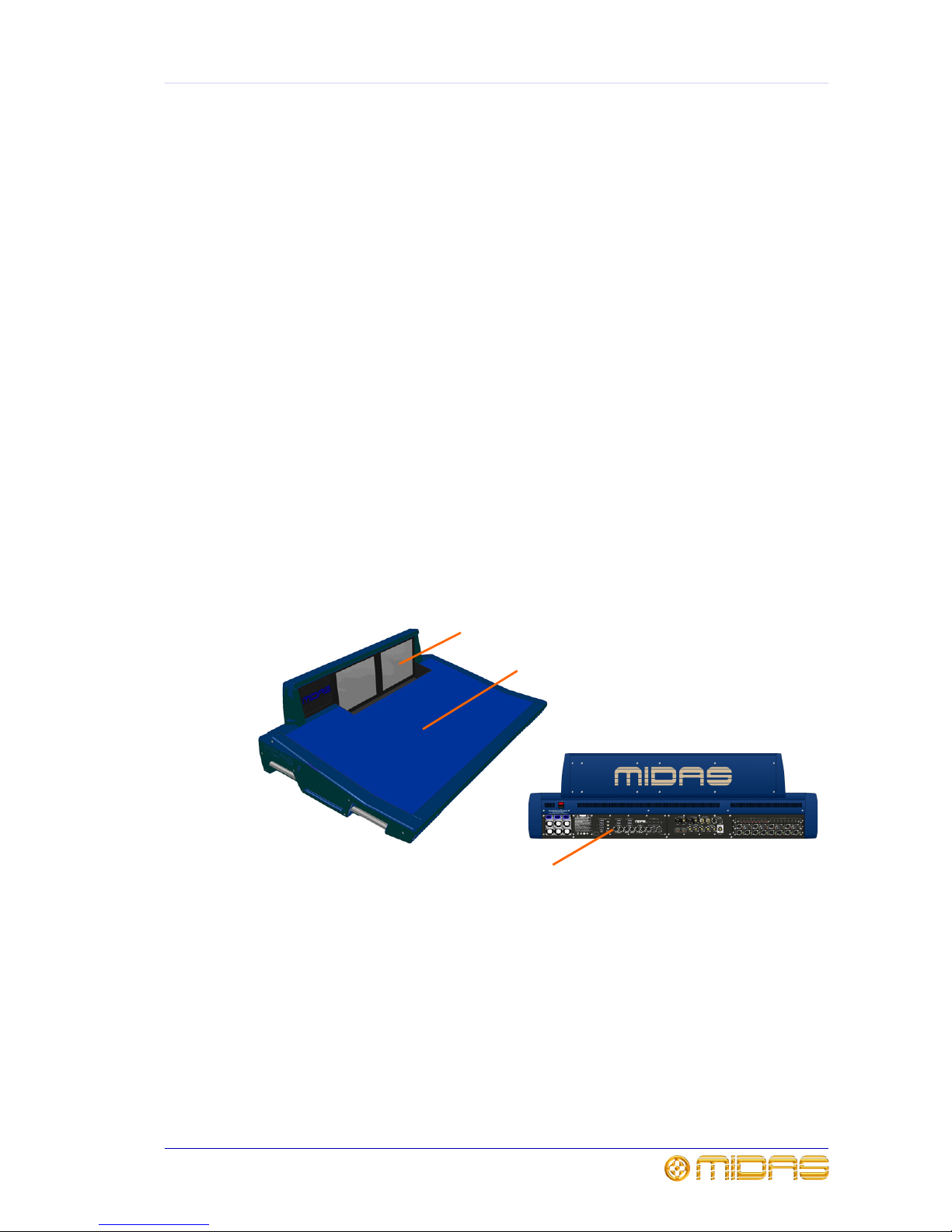
Externally, the PRO6 Control Centre has three main areas: control surface, GUI and
rear panel. The control surface is populated with instantly recognisable controls that
are logically distributed in major sections. The GUI, which comprises two screens at the
top of the centre bays, enhances operation by providing visual representations of the
control surface and also gives you extra functionality. The rear panel provides all of the
console and network connectivity, and houses the mains power sockets and isolator
switch.
Being of modular design, the overall form and shape of the PRO6 is similar to Midas’
flagship XL8. The PRO6 is split into bays, each one containing a flat fader tray and
shallow raked control area. The centre bays also have a third area that houses a
steep-raked display screen.
GUI screens
Control surface
Connector panel
Rear view
Page 20
6 Chapter 2: About The PRO6 Control Centre
PRO6 Control Centre
Quick Reference Guide
Multiple hardware fault types are tolerated by the PRO6 Control Centre without loss of
audio control due to the dual redundancy and N+1 methods incorporated in the system.
This is further helped by the modular nature of the bays and GUI independence. Either
of the GUI screens can be used to operate the whole PRO6 Control Centre, even if none
of the control surface hardware is working. The unit offers the facility of universal
input, N+1 redundant power supplies with three latching mains connectors.
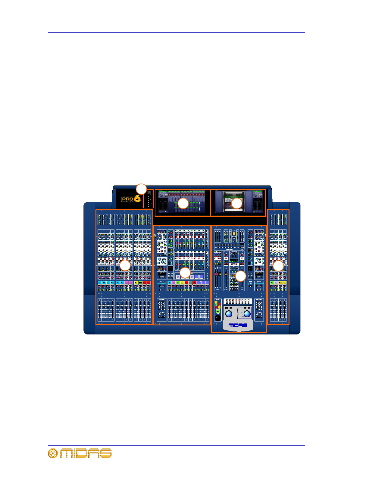
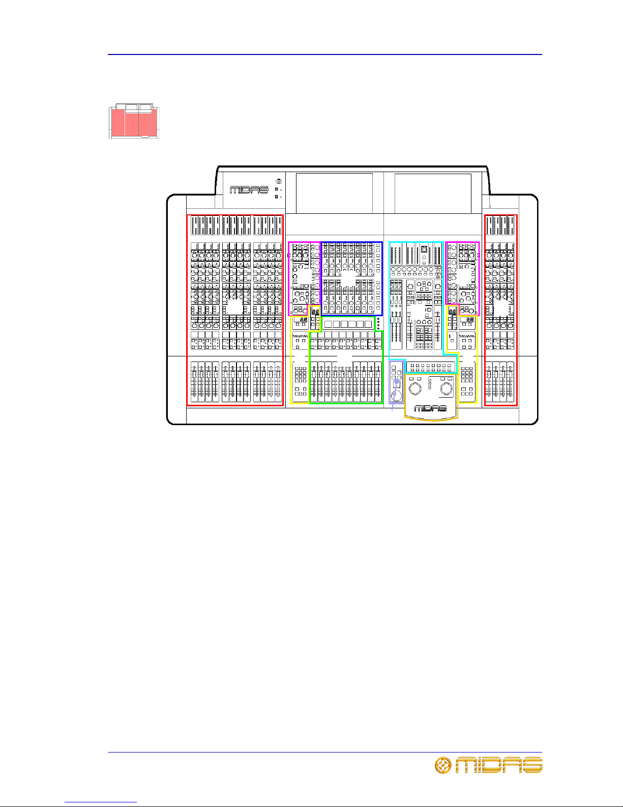
Bay and GUI layout
The PRO6 Control Centre has four discrete bays that house the following control surface
controls:
• Input bays (12-channel and 4-channel) — two input bays provide fast access to
input faders and important signal processing controls.
• Mix bay — provides access to outputs and groups, a detailed processing controller
(all channels) and navigational controls.
• Master bay — provides access to the master output mixes, monitor (A and B)
faders, automation, comms control, assignable effects control, and another set of
detailed processing and navigational controls.
Figure 1: Bay and GUI layout
Two GUI display screens at the top of the central bays provide extensive screen support
(standard configuration) and extra functionality for the channels and buses. For
example, when mixing or processing. They also facilitate the use of the GUI menu,
which gives you access to the many powerful features of the PRO6, such as patching,
effects, GEQs, diagnostics etc.
6
1
2
5
3
4
1 Input bay (12-channel).
2 Mix bay.
3 Master bay.
4 Input bay (4-channel).
5 Mix bay GUI screen.
6 Master bay GUI screen.
7 Talk mic and USB
connectors.
7
Page 21
PRO6 control surface 7
PRO6 Control Centre
Quick Reference Guide
PRO6 control surface
The control surface of the PRO6 Control Centre is divided into areas (see Figure 2)
whose function is, largely, dependent on bay location. Each bay has assorted control
elements with local feedback and/or support from the two centrally located GUI display
screens. The screens can be remoted via external VGA connections, and third party
systems can also be viewed/controlled via an integrated KVM switch on the rear panel.
Figure 2: Main areas of the control surface
A A
B
D
E
G
H
A — input fast zone: 16 input fast
strips across the 12-channel and
4-channel input bays provide the
operator’s ‘must have now’ controls.
B — channel strip and mixes:
processing areas, such as the D-zone
(dynamic), E-zone (EQ) and mix controls,
provide a more comprehensive control by
allowing detailed adjustments to a single
channel’s audio parameters.
C — channel and bus navigation
zone: sections for channel and bus
navigation and selection. For details, see
Chapter 4 “Navigation”.
D — output fast zone: 16 output fast
strips can be used for mixing and
processing aux, return, matrix and
master channels. Navigation and flip
buttons are on the right of the output fast
strips.
E — VCA and POP groups: VCA faders
and POP group sections.
F — miscellaneous: master fast strips,
A and B signal path monitoring,
communications, I-zone, surround
monitoring and mute groups.
G — primary navigation zone:
trackballs for mix and master bay GUI
screen control, and a screen access panel
(between trackballs) for direct access to
GUI menu options.
H — automation: scene store/recall
and system edit.
C
C
F
B
Page 22
8 Chapter 2: About The PRO6 Control Centre
PRO6 Control Centre
Quick Reference Guide
During show time the screen functions that require fast access are controlled by control
knobs, pushbutton switches, faders etc. More complex functions that do not require
this fast access are controlled by the trackballs and navigational keys. A keyboard
integral to the flight case is used for text entry via the master bay GUI screen. An
external USB keyboard can be used to operate the mix bay GUI screen.
The choice of controls provided by each bay type are prioritised by access time
importance. Fast zone areas, which contain fast strips, give instant access to specific
functions across the bay and channel strips give greater control of the selected fast
strip.
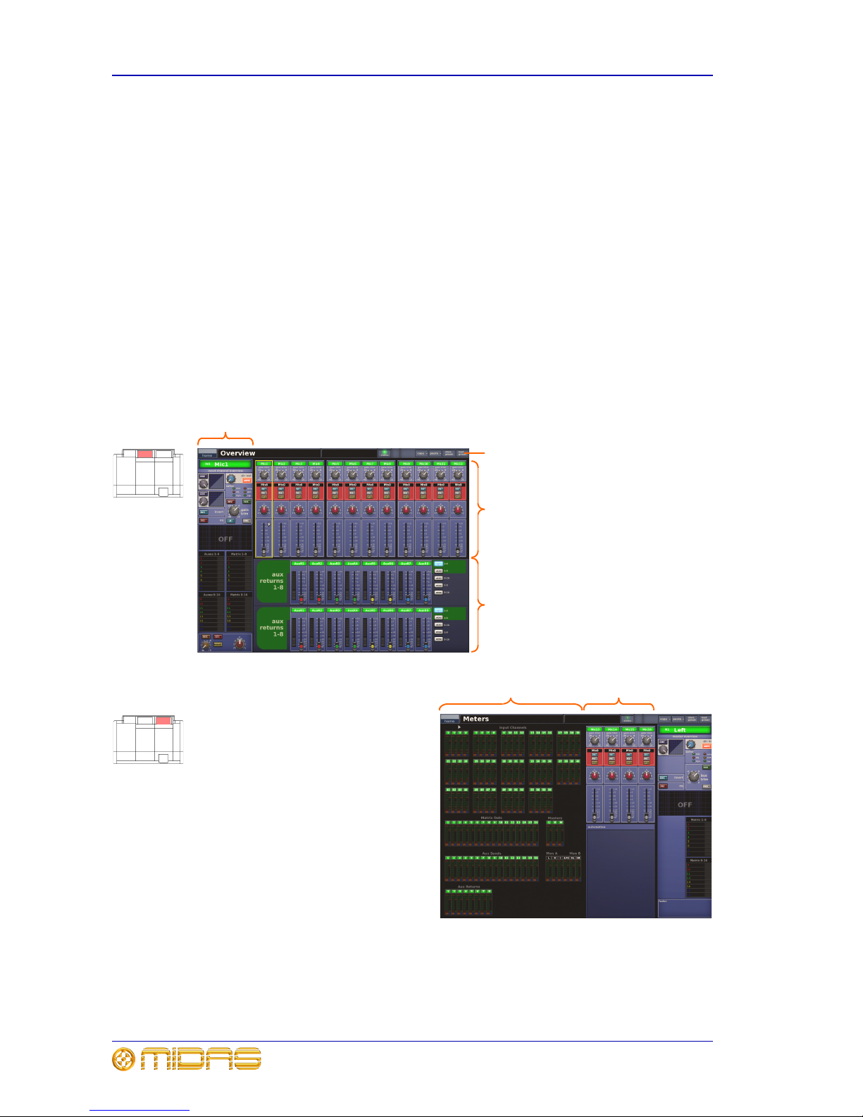
GUI
The GUI comprises two screens that provide a pictorial representation of the control
surface layout so that its displays are easy to follow at a glance. Not only does it reflect
what is happening on the control surface, but it also provides extra functionality via a
GUI menu. This menu provides access to all the screens that you will require to set up,
configure, manage and operate the entire PRO6 Control Centre, all from a single dropdown list of easy to follow options.
Figure 3: Layout of the GUI screens
Channel
strip
Overview screen
(mix bay GUI screen)
InputsOutputs
All meters display
Inputs and
automation
summary
Meters screen
(master bay GUI screen)
Banner
Page 23
Front panel connections 9
PRO6 Control Centre
Quick Reference Guide
Each GUI screen has its own default display (Overview and Meters as shown in
Figure 3), although either is selectable via the GUI main menu. The Overview screen
displays 12 inputs and two sets of eight outputs, and the Meters screen shows all the
meters, four inputs and a summary of the automation. Both screens have a banner at
the top, which is constantly displayed, and a channel strip down the outermost side.
The channel strips have a similar function to the ones on the control surface (see
Figure 2 on page 7), but provide extra functionality. Each displays an ‘overview’ of the
associated selected channel, which is divided into specific sections that provide access
to processing areas.
Front panel connections
The panel to the left of the mix bay GUI screen (item 7 in Figure 1) has an XLR socket
and two USB sockets for connecting a talk mic and USB devices, respectively. For
example, you can connect a USB memory stick for show file backup and transfer, or a
USB keyboard for text editing on the GUI.
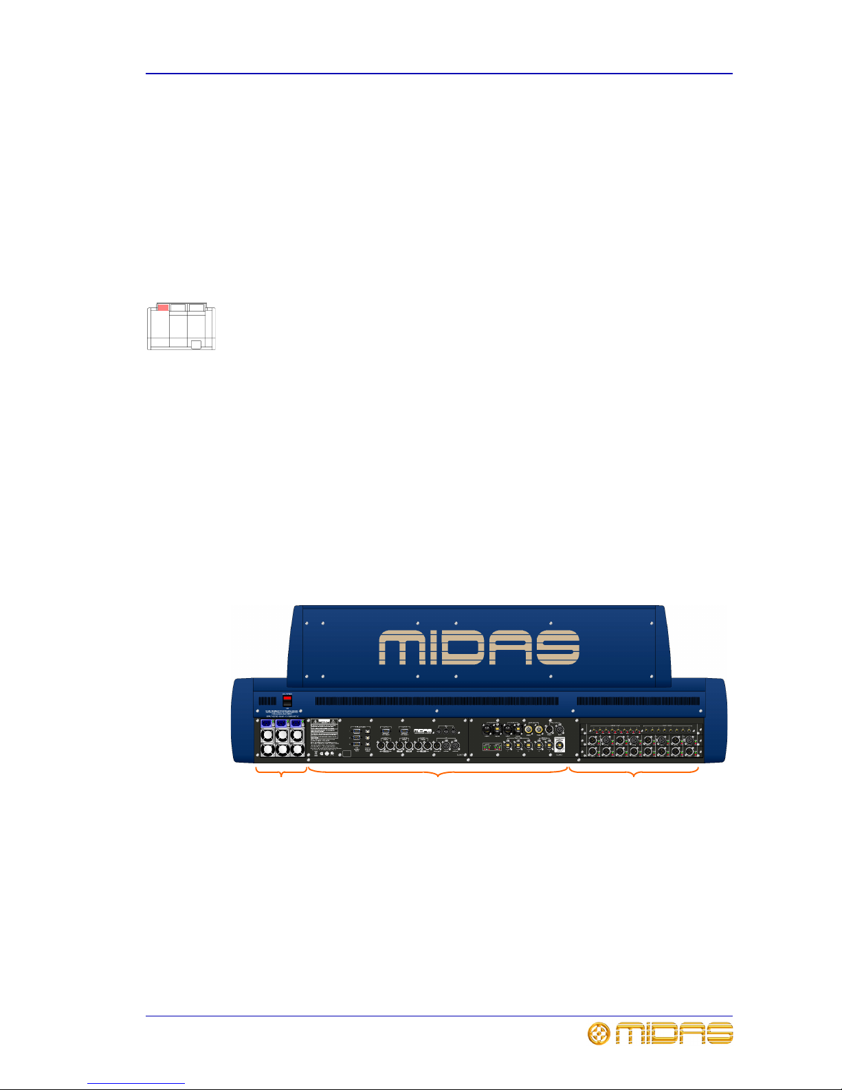
Rear panel connections
A connector panel on the rear of the PRO6 Control Centre has three main sections (see
below). On the left are three mains power inlet and ventilation assemblies, with a
DC power switch above. The mid-section contains connections for the audio, network,
communications, intercoms, synchronisation, external remote devices and peripheral
devices. The section on the right is the user-configurable modular I/O section.
The modular I/O section can house up to three of any of the following I/O modules in
any combination: DL441 analogue input module; DL442 analogue output module;
DL443 analogue insert input/output module; and DL452 digital in/out (AES/EBU)
module. This gives a maximum of 24 inputs and 24 outputs, if the appropriate cards
are fitted. The following diagram shows the standard I/O module configuration in which
the DL443 (top), DL441 (middle) and DL452 (bottom) are fitted.
Mains power
and ventilation
Audio, control
and networking
I/O
Page 24

10 Chapter 2: About The PRO6 Control Centre
PRO6 Control Centre
Quick Reference Guide
Page 25

PRO6 Control Centre
Quick Reference Guide
Volume 1:Operation
Page 26

Page 27

13
PRO6 Control Centre
Quick Reference Guide
Chapter 3: Working With The PRO6
Control Centre
Although many controls on the PRO6 Control Centre are similar to their equivalent
analogue-type counterparts, some have been specifically designed for the PRO6,
particularly those for navigation and GUI operation. As you will probably have had
experience on analogue consoles, you will already be familiar with most of the PRO6
controls and their operation. Therefore, this chapter only deals with the GUI controls
that may be new to you.
The navigational controls, such as quick access buttons and scroll buttons, are
described in Chapter 4 "Navigation" on page 17, and the ones specifically for
automation can be found in “Managing the scenes” on page 48.
Basic GUI operation
This section explains the basic procedures you can perform at the GUI screens. In
general, you will control and operate the GUI by combining the operations described
here.
Figure 4: Controlling the GUI
Each trackball controls the movement of a pointer on its respective GUI screen (see
Figure 4). The left trackball operates the mix bay GUI screen and the right one
operates the GUI screen in the master bay. Each trackball has two buttons, which have
similar functionality to the buttons on PC/laptop mouse. The left button is used in click
and drag operations, while the right button is generally used for editing and finer
control operations.
>> To operate a trackball
Rotate it by placing a finger on it and then moving your finger. The on-screen pointer
will move accordingly.
Trackball
Left trackball button
Right trackball button
Page 28

14 Chapter 3: Working With The PRO6 Control Centre
PRO6 Control Centre
Quick Reference Guide
Click
Moving the pointer to a specific point of the GUI screen and pressing the left button is
called “clicking”. This is fundamental to GUI operation and forms the basis of many of
its operations, such as switching a button on/off, selecting list and menu items, text
editing etc. Doing the same with the right button is called “right-clicking”.
Drag
Moving the pointer to a specific point of the GUI screen and then pressing the left
button while moving the pointer up/down/left/right is called “dragging”. Dragging is
used mainly to adjust control knobs and faders, and to move sliders (attached to
drop-down lists)—although it is also used to select blocks of connectors when patching.
The pointer disappears when the control has been selected to show that it is ready for
adjustment.
Operating the GUI screen controls
This section shows you how operate GUI screen elements, such as buttons, control
knobs, drop-down lists and sliders.
>> To switch a GUI button on/off
Click the button. If it has a status indicator, this will illuminate/extinguish to show that
it is on/off, respectively.
>> To adjust a GUI control knob or fader
Use a drag operation. Move the pointer up/down/left/right for adjustment.
>> To select an option from a drop-down list
1 Click the drop-down arrow. The drop-down list
will unfold to display some or all of its contents,
depending on how many items it contains.
2 Do one of the following:
• Click the option you require.
• If necessary, scroll the list (see “To scroll a
drop-down list” below) to display the option, and then click it.
>> To scroll a drop-down list
With the drop-down list displayed, do one
of the following:
• A. Drag the scroll box.
• B. Click the scroll bar. The scroll box
will ‘jump’ in the direction of the click
to another position in the scroll bar.
• C. Click an up/down scroll arrow. The
scroll box will ‘jump’ in the direction of
the scroll arrow to another scroll bar
position. Clicking a scroll arrow when
the scroll box is adjacent to it has no
effect.
Drop-down
arrow
Currently selected
list item
Scroll arrow
Scroll bar
Scroll box
B
C
A
Page 29

Using the GUI menu 15
PRO6 Control Centre
Quick Reference Guide
Using the GUI menu
You can access the GUI main menu by clicking the home button, which is constantly
displayed at the upper-left corner of both GUI screens. Menu options with an arrow on
the right have a submenu. The background colour of a menu option will be blue when it
is available for selection.
Throughout this guide, menu/submenu option selection sequences are shown in the
following format (for example, for choosing the general preferences screen):
home
PreferencesGeneral
>> To access the GUI main menu
Click home.
>> To select a GUI menu option
Click the menu option, for example, Monitors. The background of the menu option will
change to blue when it is ready for selection.
>> To access the submenu of a GUI menu option
Move the pointer over the arrow on the right of the menu option. The submenu will
appear automatically to the right of the arrow. Click an option in the submenu to select
that option.
GUI main
menu
Right arrow
shows that the
option has a
submenu
Page 30
16 Chapter 3: Working With The PRO6 Control Centre
PRO6 Control Centre
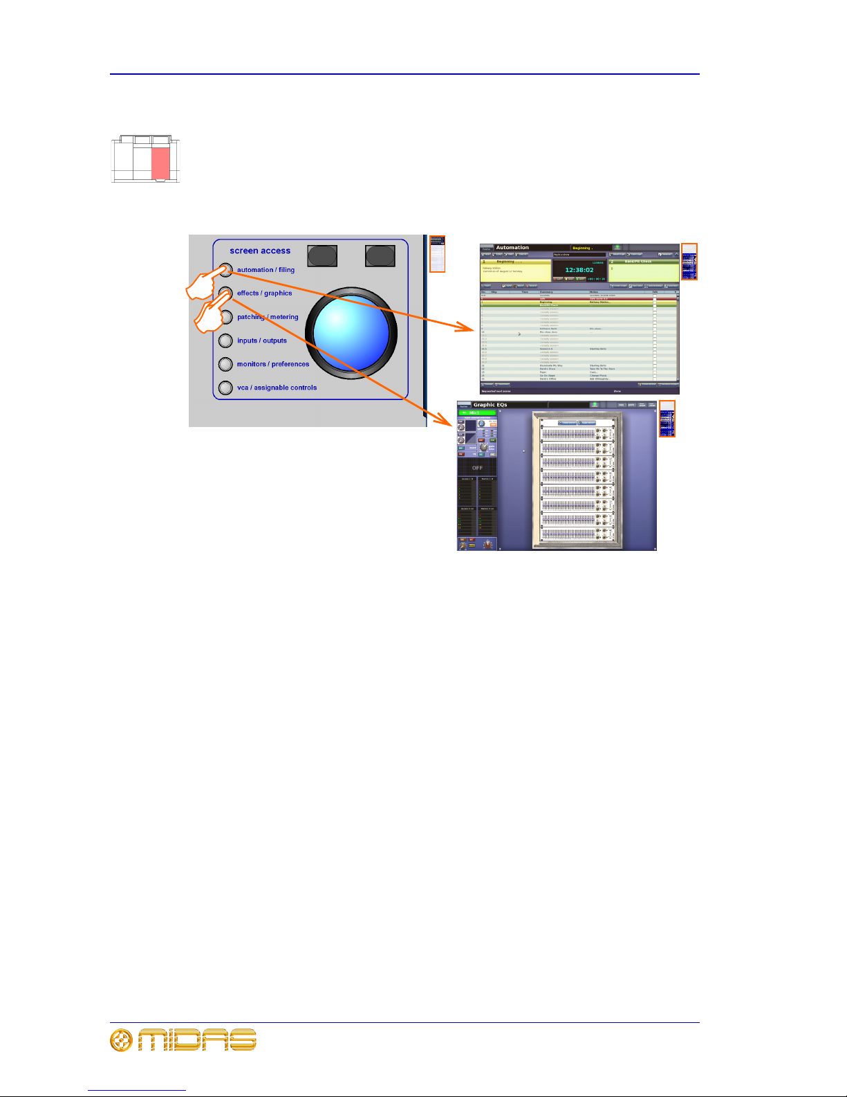
Quick Reference Guide
Accessing a GUI menu screen using the screen access buttons
You can access some of the GUI menu screens simply by pressing a button, instead of
using the GUI menu. This is done by using the screen access buttons in the primary
navigation zone. Each button provides direct access to two screens, the title of which
are printed next to the button. The first screen mentioned is accessed by a single
button press, while the next is accessed by a double press. An example of each is
shown in the following diagram.
Text editing
A keyboard is used to type in text on the GUI, for example, to configure input and
output channel names. Editable text on the GUI is contained in text boxes, which
generally consist of a single line of limited length. Although all text editing can be done
using the normal keyboard functions, the GUI can be used to assist you, for example,
by highlighting portions of text (using drag).
>> To enter/edit text via the keyboard
1 At the GUI, click in the text box to place an insertion point in it. The pointer will
change to an I-beam shape.
2 Using the keyboard, type in the new text. If the text box already contains some
text, you can delete this first or edit it, which can be done via the keyboard or by
using the cut, copy and paste options after right-clicking.
3 Press Enter on the keyboard to exit the text box (or click on an empty area of the
GUI screen). The pointer’s shape will change back to an arrow.
Page 31

17
PRO6 Control Centre
Quick Reference Guide
Chapter 4: Navigation
This chapter introduces you to PRO6 navigation and shows you how to use the
navigational tools of the PRO6 Control Centre.
For information on navigating the scenes in automation, refer to “Managing the scenes”
on page 48.
An introduction to PRO6 navigation
The PRO6 provides you with unique navigational controls to quickly and easily access
the items, such as channels, buses, groups and processing areas, that you will require
for mixing.
Navigation is an important feature of the PRO6 Control Centre. One of the advantages
digital consoles have over analogue ones is that their channel count is not limited by
the control surface hardware. However, this means that only a certain amount of
channels can be at the control surface at any time, while the others are ‘hidden’. So,
navigation is required to access these hidden channels whenever you need them.
The way the PRO6 is set to operate may alter the function of some of the navigational
controls. For more information, see “Operating modes” on page 31.
How the input channels are managed
To aid navigation the 56 input channels are grouped into 14 ‘banks’ of four channels
each. The banks contain the following consecutively numbered channels: 1 — 4,
5 — 8, 9 — 12 etc., up to 53 — 56. (Figure 5 shows the number of consoles required to
show all of the available inputs simultaneously.)
Figure 5: All inputs
During normal operation, four banks of input channels populate the input bays (see
Figure 6 “Input channels in the input bays” on page 18). These are displayed across
the control surface in ascending order from left to right.
Note: The rigid bank (four-channel) structure does not apply to groups, as their
contents are dependent on what channels are selected as group members.
1-12 13-16 17-28 28-32 33-44 45-48 49-56
Page 32

18 Chapter 4: Navigation
PRO6 Control Centre
Quick Reference Guide
Figure 6: Input channels in the input bays
About the navigational controls
The PRO6 navigational controls can be broadly divided into two main areas: those that
operate the channels currently populating the control surface (quick access buttons and
LCD select buttons) and the ones that navigate channels to/from the control surface
(scroll buttons and output select buttons)—although there may be some overlapping.
Quick access buttons
Quick access buttons help you to quickly select the channel, mix bus or processing area
you want. The buttons, which are round and translucent, illuminate (blue) when active.
The quick access buttons in fast strips select their local channel and assign their local
processing area to the associated channel strip. The ones in the channel strips select
their local processing area, but don’t affect channel selection.
LCD select buttons
LCD select buttons select their local input channel/group (VCA/POP). The buttons are
square and have an LCD display, which can be backlit. The display provides useful
feedback by showing you information, such as channel/group name, and by identifying
the group from the user-configured backlight colour. When selected, the display
changes to a ‘negative’ image.
For more information on how to use the group LCD select buttons, see “Using VCA/POP
groups” on page 39.
Scroll buttons
You can scroll through the channels/mixes by using the pairs of scroll buttons located in
the ‘select’ sections of the mix and master bays (see Figure 7 on page 20). The
direction of scrolling matches the analogue convention, where channels are left/right
and mixes are up/down. The buttons are translucent and have a blue backlight that
illuminates when pressed.
The scrolling action of the buttons (or the number of channels/buses scrolled per press)
varies according to their location. For more details, see “About the navigation ‘select’
sections” on page 19.
Output select buttons
The output select buttons navigate their associated bank of outputs to the control
surface. The buttons are translucent and have a blue backlight that illuminates when
pressed; the backlight stays on to show you which bank of outputs is currently
populating the control surface.
Three banks of four
input channels each
(12 channels in total),
which are also shown
on mix bay GUI screen
A single bank of four
input channels,
which are also shown
on master bay GUI
screen
Page 33

About the navigation ‘select’ sections 19
PRO6 Control Centre
Quick Reference Guide
Channel select (lower) and channel type sections
The Channel select (lower) and channel type sections are used in combination to
navigate a single channel to the control surface, which is generally used for rectifying a
fault on a problem channel.
ALIGN button
The ALIGN button (both input select sections) navigates the currently selected
channel to the local input bay. This is useful, for example, if you have scrolled away
from the selected channel on the control surface and you want to get the fader back.
B button
The B button (master bay input select section only) assigns the 4-channel input bay
as area B. This operates with the channel strip on the right (in the master bay).
Right arrow (to right channel) button
The right arrow (to right channel) button — to the right of the top output select
buttons — assigns the channel strip, navigation controls and sends in the master bay to
the top row of outputs.
About the navigation ‘select’ sections
The ‘select’ sections in the mix and master bays (see Figure 7 on page 20) are used for
navigating the channels and mixes, and also show you which ones are currently
selected. They have the following functions:
• channel select (upper) section — scrolls either the input or output fast strips
(depending on selected channel type) channel-by-channel. Current channel
selection follows the scroll, which is shown on the section’s display, along with the
channel type.
• input select section — scrolls the inputs in banks (of four). Shows you which banks
of inputs currently populate the control surface by illuminating the appropriate bank
LEDs. When using VCA/POP groups, an LED will flash if its bank contains a
channel(s) that are members of the selected group, but don’t currently populate the
control surface. This section also has an ALIGN button and a B button (master bay
only).
• mix section — scrolls the mix buses singly or in banks of eight. Shows you the you
the number and type (aux or matrix) of the currently select mix bus. The quick
access button assigns the currently selected mix bus to the channel strip.
• channel select (lower) and channel type sections — see “Channel select (lower)
and channel type sections” above.
How to navigate
This section shows you how to navigate the channels, mixes and groups, and how to
select the ones you want. Refer to Figure 7 “Location of the navigational controls on
the control surface” on page 20 throughout this section.
In many cases there are a number of navigational methods you can choose from to
carry out a particular task. Some may be more suitable than others in a given situation
and there may even be a combination of methods you an use. Experience should guide
you to the most appropriate and the ones you most prefer.
Page 34

20 Chapter 4: Navigation
PRO6 Control Centre
Quick Reference Guide
Figure 7: Location of the navigational controls on the control surface
1
1
1
1
1
1
1
1
1
1
2
1
1
1
1
2
1
1
1
5
3
3
3
2
3
4
Key:
1 Quick access buttons
2 LCD select buttons
3 Scroll buttons
4 ALIGN button
5 Output select buttons
6 Right arrow button
7 FLIP button
A Input fast strip
B Channel strip
C channel select
(upper) section
D input select section
E channel select
(lower) section
F channel type section
G mix section
H VCA group strip
I Output fast strip
J population groups
(POP groups) section
K Master fast strips
Note: Items A to G are replicated on the far right side of
the control surface, although the master bay’s input
select section also has an area B button.
A
B
C
D
E
F
G
I
K
H
J
5
6
7
Page 35

How to navigate 21
PRO6 Control Centre
Quick Reference Guide
Switching between inputs and outputs
You can easily change from working with inputs to working with outputs, and vice
versa. To switch channel type, simply select any channel of the type you want to switch
to. The channel select (upper) section shows which type of channel is currently in
operation (and the channel number selected).
>> To change channel type
Do one of the following:
• Press a quick access button in a fast strip of the required channel type.
• To change to inputs from outputs, press an LCD select button in any input fast strip.
Navigating channels and mix buses to the control surface
There are a number of ways in which you can bring channels and mix buses to the
control surface, particularly using the scroll buttons.
>> To navigate a channel to the control surface
With the channel type you require currently in operation, do one of the following:
• Scroll to the channel using the scroll by 1 buttons in the channel select (upper)
section. This will also select the channel.
• If you are currently operating the inputs, scroll the bank containing the input
channel you require to the control surface using the scroll by 4 buttons in the input
select section.
• If you are currently operating the outputs, navigate the bank containing the output
channel you require to the control surface by pressing its output select button (in
either the top or bottom output fast strip sections).
>> To navigate an input channel to a fast strip on the control surface
Press ALIGN.
>> To navigate a mix bus to the control surface
Do one of the following:
• Scroll to the mix bus using the scroll by 1 buttons in the mix section. This will also
select the mix bus.
• Scroll the bank containing the mix bus you require (aux or matrix) to the control
surface using the scroll by 8 buttons in the sends section.
Selecting channels, mix buses and groups
There are a number of ways you can select a channel/mix bus from those currently
populating the control surface, particularly by using the quick access buttons.
>> To select an input channel
Do one of the following:
• Press its LCD select button.
• Press any of its quick access buttons. This will also assign the channel to the
channel strip and its processing area to the GUI channel strip.
Page 36

22 Chapter 4: Navigation
PRO6 Control Centre
Quick Reference Guide
• Scroll to the input channel using the scroll by 1 buttons in the channel select
(upper) section.
>> To select an output channel
Do one of the following:
• Press its quick access button. This will also assign the channel to the channel strip
(control surface and GUI).
• Scroll to the output channel using the scroll by 1 buttons in the channel select
(upper) section.
>> To select a mix bus
Scroll to the mix bus using the scroll by 1 buttons in the mix section.
>> To select a group
Press its LCD select button.
Navigating a processing area or mix bus to a channel strip
You may want a specific processing area assigned to a channel strip, for example, to
carry out processing or for copying to other channels. Or, you may want to carry out
detailed processing on the currently selected mix bus, but it may not necessarily be
assigned to its associated channel strip.
>> To navigate a processing area to a channel strip
Do one of the following:
• If its channel is already selected, press its quick access button in the channel strip.
This will also assign the channel to the channel strip (control surface and GUI).
• If its channel is at the control surface, but is not currently selected, press its quick
access button in the fast strip.
>> To navigate the selected mix bus to a channel strip
Press the quick access button in the mix section. This does not affect the current
population of the output fast zone.
Fault finding a problem channel
If you know the number of the channel that has a problem, you can quickly navigate it
to the control surface by typing in its channel type and number via the channel select
(lower) and channel type sections.
>> To navigate a channel using its number
1 In the channel type section, press the button corresponding to the channel’s
type. For example, if the channel is an input, press INPUT.
2 In the channel select (lower) section, type in the channel’s number. For
example, press 4 and then 7 for channel 47.
3 Press ENTER.
Page 37

23
PRO6 Control Centre
Quick Reference Guide
Chapter 5: Patching
This chapter describes the patching feature of the PRO6.
Introduction
Patching is a GUI-only feature that allows you to carry out all the routing requirements
of the PRO6. The GUI main menu has a Patching option that takes you to the
Patching screen (shown below), which contains all of the available patching connectors
on the PRO6. This screen provides an easy-to-use interface, where you can select your
source and destination patching options, facilitated by a panel of function buttons.
Additionally, the Patching screen allows you to set up the units (devices). For
example, you can adjust the analogue gain, select +48V phantom voltage etc., of the
line I/O units connected to the system.
1
1 Function button panel, contains the
function buttons that enable patching and
device configuration (see “Function buttons” on
page 24).
2 Patching area, contains all of the patch
connectors on tabs.
3 From section, has tabs that contain all of
the patch connector sources.
4 To section, has tabs that contain all of the
patch connector destinations.
5 Tab n am e s .
43
2
5
Page 38

24 Chapter 5: Patching
PRO6 Control Centre
Quick Reference Guide
>> To access the Patching screen
Do one of the following:
• At the GUI, choose home
Patching.
• Press the routing/metering button in the primary navigation zone.
• At the appropriate GUI screen, click the src (source) or dest (destination) button.
The Patching screen will open at the appropriate tab/configuration window.
Function buttons
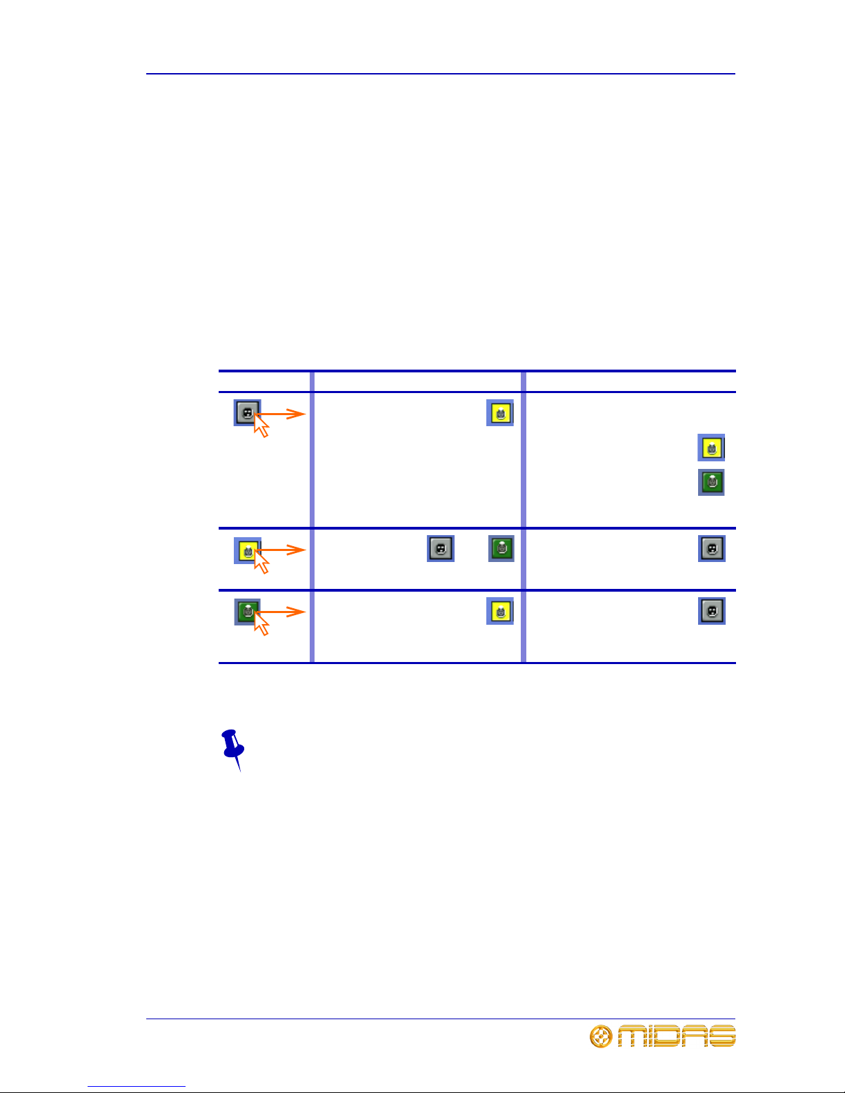
The function buttons are described in Table 1 “Description of the function buttons”.
Click a function button to select it; its background colour will change to a lighter shade
when selected.
Table 1: Description of the function buttons
Button Description
Allows you to patch a single source to a single destination or multiple destinations.
See “Single patching (SINGLE)” on page 30.
Lets you select multiple sources and patch them one by one to their destinations. In
this method, each source can only have one destination. See “Sequence patching
(SEQ.)” on page 30.
Allows you to select a block of sources and patch them all automatically, simply by
selecting a single destination. Any existing patches within the destination range will
be replaced by the new ones.
Clears all currently selected patch connectors from all tabs in the From and To
sections. The green triangles will disappear accordingly.
Changes the tooltip type from standard to list, but is only available when carrying out
a sequence patching operating via the SEQ. button. The list tooltip, which has a
distinctive translucent orange background, appears in the To section when you are
patching the destinations of a number of selected sources. The list contains a queue
of sources waiting to be patched; the first in the queue is at the bottom of the list.
Sets a patching store point that contains the patching status at that instant. There is
only one checkpoint available, so each time CHECKPOINT is clicked the previous
checkpoint is overwritten.
Reverts patching status to the last checkpoint or, if no checkpoints have been
created, it will revert patching status to the power up condition. All patching done in
the intervening period will be lost.
Undoes the latest single patch, even if it was part of a multiple patching operation.
Repeated clicks will undo the preceding patching operations, going back to the last
checkpoint, or power up if no checkpoints have been created.
Redoes an undo. This can be repeated for each undo in the previous undo operation.
Clears all current selections and their patches.
Important:
Unlike the NONE button, which merely removes the current selections
(highlighted in yellow), CLEAR SEL. goes a step further by removing the
patch as well. This will stop any audio that may have been going through
the patched signal.
Page 39

About the patching procedure 25
PRO6 Control Centre
Quick Reference Guide
About the patching procedure
Although patching can be thought of as routing/rerouting the console’s incoming,
internal and outgoing signals, in the context of the Patching screen, patching also
encompasses the setting up and configuration of the stage and FOH rack I/O devices.
The patching procedure is initially carried out after system installation and comprises:
• Device configuration: Configure the devices by adjusting their parameters (see
“Configuring the devices” on page 25).
• Snake selection: Configure the PRO6 according the type of ‘snake’ you are using
for the X and Y networks (see “Configuring the PRO6 with the snake type” on
page 27). This is important, as the PRO6 Control Centre will not work unless
the snake type is correctly configured.
• Setting up the I/O rack devices: Set up the system devices, such as line I/O,
DN9696 and generic AES50, to the I/O tabs in the From and To sections of the
Patching screen (see “Setting up the I/O rack devices” on page 27).
• Patching: Carry out all of the required routing, for example, mics to input channels
(see “How to patch” on page 29).
Configuring the devices
You have the option to configure the devices from the Patching screen. Parameters,
such as gain and +48V phantom voltage, can be adjusted or switched on/off,
respectively via a device-specific configuration window.
These configuration settings can be independent of channel data, as (until patched)
they only control the physical unit. If a device is subsequently patched to one or more
channels, the channel(s) control the device, and vice-versa.
The device configuration area also allows control of audio parameters when the device
is used as a direct connection to another device, for example, FOH to stage via a digital
snake, instead of through the DSP. In this case the settings are also saved in the show
file and can be automated, even though the signals are not routed through the console
DSP.
Device configuration procedure
Although the procedure for configuring the devices is similar, their parameters are
dependent on device type. The procedure for configuring the devices of a similar type
involves:
• Opening the configuration window of the device.
• Selecting one of the device’s cards/channel ranges and configuring the available
parameters.
• Repeating for the other cards/channel ranges of the device.
Clears all patching.
Important:
Exercise great caution when using this function. Observe the warning that
appears after clicking this button.
Opens the input/output setup window, from where you can set up the I/O tabs in
the Patching screen (see “To add a device or change its set up” on page 28).
Button Description
Page 40
26 Chapter 5: Patching
PRO6 Control Centre
Quick Reference Guide
• Repeating for the other devices.
• Closing the device’s configuration window.
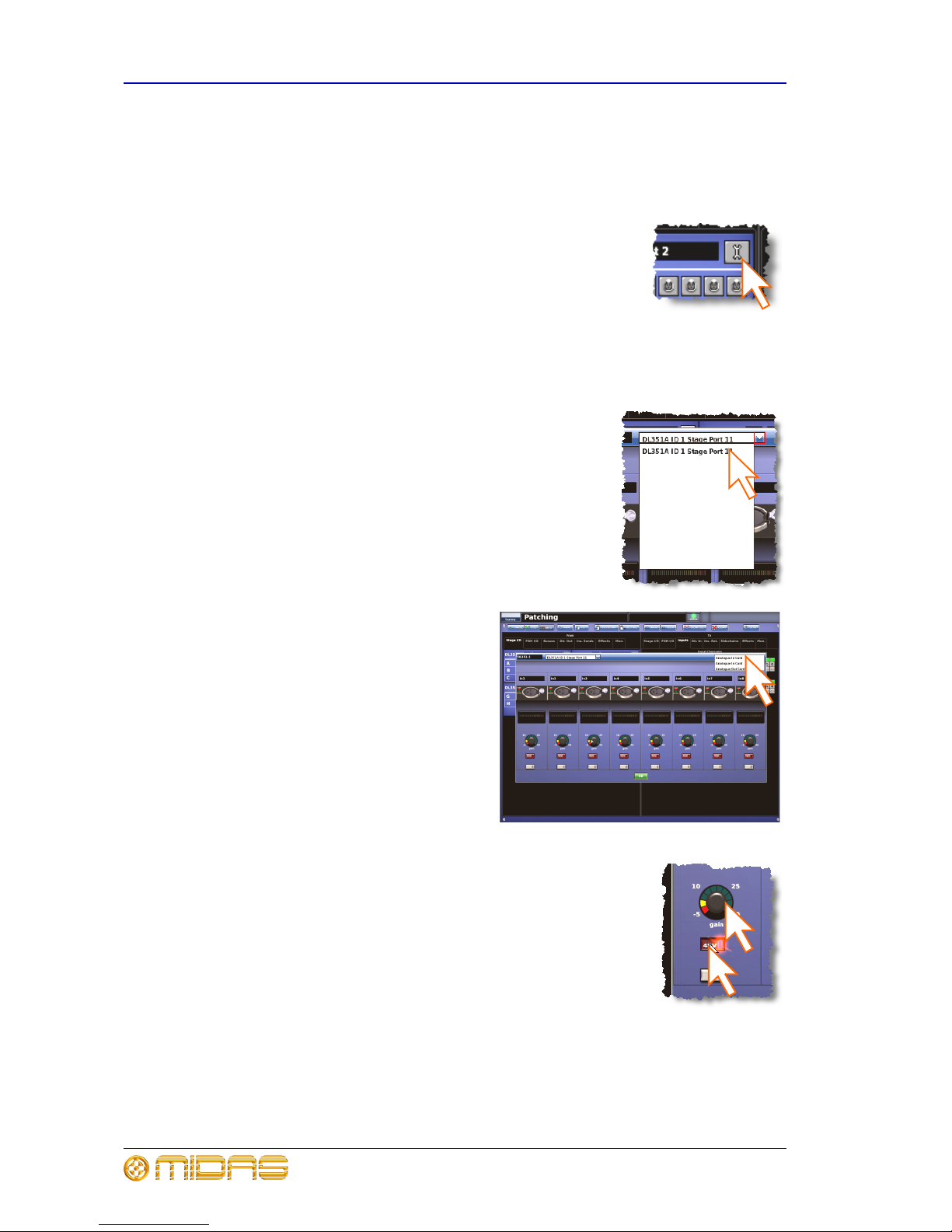
>> To open the configuration window of a device
Click the device’s spanner button.
>> To set up/change the configuration of an I/O device
1 Open the configuration window of the I/O device you want to configure (see “To
open the configuration window of a device” on page 26).
2 Select the I/O device from the drop-down list at the
top of the configuration window.
3 Select the card/channel you want to
configure/change, from the
drop-down list at the upper-right
corner of the configuration window.
For example, the “Analogue In
Card”.
4 In a channel, configure the parameters. For example, in
channel “In1”, adjust the gain and switch the +48V phantom
voltage on (shown right).
5 Repeat step 4 for the other channels in the card.
6 Repeat step 3 to step 5 for the other cards.
7 If you want, you can configure other I/O devices by
repeating step 2 to step 6. Otherwise, click OK (bottom of
configuration window) to save the configuration changes and
close the window.
Page 41

Configuring the PRO6 with the snake type 27
PRO6 Control Centre
Quick Reference Guide
Configuring the PRO6 with the snake type
Important:
The snakes must be correctly configured before operating the PRO6.
Otherwise it will not work.
You can connect the DL371 DSP to the PRO6 Control Centre with either copper or
fibre-optic snakes. The PRO6 needs to be configured with this information before
operation can begin. This is done via the GUI menu.
>> To configure the PRO6 with the snake type information
1 At the GUI, choose homePreferencesGeneral.
2 Under the Stage Link X heading, click the Fibre or
Copper option, according to whichever is fitted to the X
network. For example, click the Copper option (shown
right). A selected option will contain a red circle.
3 Repeat for the Y network, under the Stage Link Y
heading.
Setting up the I/O rack devices
You can add, remove and set up the devices, such as line I/Os, mic splitters, DN9696s
etc., that are connected to the Stage I/O and FOH I/O racks. This is done via the
input/output setup window. Here, you can set up the device ID and also the type of
cards (modules) fitted to the physical unit. Figure 8 “input/output setup window”
shows a typical example of what the input/output setup window looks like with one
of the DL351 devices selected. The options are context-sensitive, so some may be
blank, depending on the type of device.
The DL351 Modular I/O has four devices (A, B, C and D) per unit, and each one has its
own port. The four devices represent the following:
• DL351A - cards A, B and C.
• DL351B - cards D, E and F.
• DL351C - cards G and H.
• DL351D - redundant AES50 port.
Page 42

28 Chapter 5: Patching
PRO6 Control Centre
Quick Reference Guide
Figure 8: input/output setup window
>> To add a device or change its set up
1 Click SETUP (shown right) to open the input/
output setup window.
2 In the list of ports (far left in the
input/output setup window), click the port
you want to allocate the device to. For
example, “FOH Port 3 (unused)”. The text in
the device type: field will change accordingly. (A port that has no device
allocated to it will have the text “(unused)” after its name.)
3 In the device type: drop-down list, click the type of device. For example,
“DL351A”.
4 In the device ID: drop-down list, click the ID you want for the device. For
example, “ID6”.
5 In the device options: drop-down list, click the type of card fitted physical unit.
For example, “Analogue 8 Input”. If there is more than one device options:
drop-down list, repeat for the remaining ones, making sure they match the actual
cards fitted.
6 Click OK. This will save any changes and close the input/output setup window.
1 List of Stage and FOH ports with current
device assignments.
2 device type: drop-down list, contains a
list of the available devices to choose from.
3 device ID: drop-down list, contains a full
list of IDs for the selected device type. Those
already in use will be prefixed with the text
“(In use)”.
4 device options: drop-down list(s), from
which you can select the card that is actually
fitted in the physical unit. The positions of the
drop-down lists are relative to the card
positions in the physical unit.
5 OK button, closes the input/output
setup window.
1
2
3
4
5
Page 43
How to patch 29
PRO6 Control Centre
Quick Reference Guide
How to patch
Patching, basically, involves selecting the source patching connectors in the From
section of the Patching screen and then selecting their destination(s) in the To section.
You can select patches singly, or in multiples by using the sequence and automatic
operations.
>> To open a tab in the From or To sections
Click the tab title. For example, Ins. Sends (insert sends).
>> To select a single patch connector
Click the patch connector. The effects of clicking a patch connector are shown in
Table 2 “Effects of clicking a patch connector”.
Table 2: Effects of clicking a patch connector
Selected patch connectors will turn green after another patch operation is initiated or a
function button is selected.
To quickly check the destinations of a source patch connector, click it. This will
select it and all of its destinations. A green triangle will appear under the name
of any tab in the To section that contains a destination(s).
Clicking In the From section In the To section
Selects patch the connector. Will do one of the following (provided a
source patch connector(s) has been
selected in the From section):
• Selects the patch connector
during a single patching
operation.
• Patches the patch connector
during either a sequence or
an automatic patching
operation.
Otherwise, this has no effect.
Deselects the patch
connector, which
then reverts to its
previous state
(patched or unpatched).
Deselects the patch connector.
Selects the patch connector and
all the ones it is patched to in the
To section. Shows which tabs
contain selected patch connectors
by putting a green triangle under the title
of each.
Removes the patch.
OR
Page 44

30 Chapter 5: Patching
PRO6 Control Centre
Quick Reference Guide
Single patching (SINGLE)
The SINGLE function button allows you to patch a single source to a single destination
or multiple destinations.
>> To patch a single source to a single destination
The following example shows you how to patch an output from a mic splitter to an input
channel.
1 Click SINGLE.
2 Select the source patch connector. For example, in
the Stage I/O tab of the From section, click the first
patch connector (XLR1) of card A of the DL351
Modular I/O. Its background will change to yellow
and a green triangle will appear under the tab title
(as shown right).
3 Select the destination patch connector.
For example, in the Inputs tab of the
To section, click the patch connector for
input channel 14 (Mic14). It will now be
patched to the source. If the new patch
is carrying a signal, this audio may be
heard, depending on the settings of the
PRO6 Control Centre.
Note: You can also carry out single patching
operations by using the CLEAR SEL. and
AUTO functions.
>> To patch a single source to multiple destinations
1 Patch the source patch connector to one of its destinations, as detailed in “To
patch a single source to a single destination” on page 30.
2 In the To section, select the other destinations.
Sequence patching (SEQ.)
If you need to do a number of patches, and each has only a single destination, you can
use the sequence function. All of the source patch connectors are selected in the From
section before being patched, one by one, in the To section. This saves you having to
go back to the From section for the start of each patch.
To assist you in sequence patching, you can change the tooltip to the list type (see the
LIST function button in Table 1 “Description of the function buttons” on page 24).
Page 45

31
PRO6 Control Centre
Quick Reference Guide
Chapter 6: Basic Operation
This chapter is intended to familiarise you with the PRO6 Control Centre by showing you
how to carry out some basic operations in order to get some audio out of it.
Note: As the operation of both input bays is principally the same, this chapter will
generally only show the operation of the 12-channel input bay. Although, any
differences in their operation will be shown.
Please don’t forget that, although this system is a complex, high-tech piece of
equipment, it is very easy to use.
Principles of operation
PRO6 Control Centre operation is based on the concept of colours and groups rather
than ‘layering’ or ‘paging’, which is the case with most digital consoles on the market
today. With so many channels available it is far easier to remember them by their
user-configured individual/group colour and name rather than their channel number.
The control surface is populated with instantly recognisable controls that are logically
distributed in major sections, so that all the controls you need to access most of the
time are always on the control surface, while the remainder are only one action away.
All I/O meters are permanently on display, both on the control surface and the GUI, to
give instant monitoring feedback.
Operating modes
You can change certain aspects of PRO6 operation by assigning different tasks to
certain areas of the control surface. This section will explain the different ways in which
the control surface can operate.
Normal mode
During normal operation the 12-channel input bay is operated from the mix bay
controls and GUI screen, while the controls and GUI screen in the master bay operate
the 4-channel input bay. Both input bays operate in unison and are, in effect, area A.
(The 12-channel input bay will always be area A, no matter operation mode you are
using.)
Using the 4-channel input bay as area B
You can assign the 4-channel input bay as area B, thus making both the input bays
independent from each other. This facilitates two-man operation, which is described in
“Two-man operation” on page 55.
Page 46

32 Chapter 6: Basic Operation
PRO6 Control Centre
Quick Reference Guide
Operating the top output fast strips from the master bay
During normal operation, both rows of output fast strips — which are always
independent from each other — are operated using the controls in the mix bay.
However, you can assign the master bay to control the top row of output strips.
>> To switch control of the output strips to the master bay
Press the right arrow (to right channel) button (see Figure 7 “Location of the
navigational controls on the control surface” on page 20).
Controlling the mix buses in flip mode
Flip provides a more global approach to mix bus level control. Normally, you can only
use the level control knobs in the channel strips to adjust the signal level of the
aux/matrix mix buses going to the masters. However, by using flip you have the option
of controlling them from either the pan control knobs or the faders in the input fast
strips.
In flip mode the channel select (upper) section scrolls across the input fast strips.
>> To configure the PRO6 for pan or fader flip
1 At the GUI, choose homePreferencesGeneral.
2 Depending on which option you require, click the option button of one of the
following in the Fader flip section. When an option is selected, it will contain a
red circle:
• “Flip to faders”.
• “Flip to Pans”.
>> To flip mixes to input pan/fader control
With an output selected on the control surface, press FLIP (see Figure 7 “Location of
the navigational controls on the control surface” on page 20). The button will illuminate
to show you are in ‘flip’ mode. The currently selected mix bus in the input channels will
change to AuxS1 and, on the GUI, the background of the pans and faders will change
accordingly. Also, the LCD select buttons in the input fast strips will display the current
bus mode, for example, “MONO AUX”.
Hints and tips
• Check what is hidden: On the PRO6, unlike on an analogue control surface, some
of the settings and parameters will be hidden from view (stored in the computer
memory of the PRO6). At various times during a mix we recommend that you select
and view unused parameters to make sure there are no hidden surprises, for
example, a reverb send left from a previous mix.
• Check the Meters screen: It is a good idea to frequently monitor the Meters
screen (default display of the master bay GUI), which provides at a glance an
overview of the console’s status and operation. It shows all the meters and the
status condition of faders and some switches, such as solos and mutes. However,
some things will still remain hidden.
Page 47

Saving your work 33
PRO6 Control Centre
Quick Reference Guide
Saving your work
We recommend that you save your work regularly while carrying out the procedures
included in this chapter. Not only is this good practise during normal PRO6 operation,
but in this instance it may save you from losing some set-ups that could prove useful
later on. To do this, create a new show (see “To access the Automation screen” on
page 46), and then continue reading through the remainder of this section, following
the instructions carefully. Save your work at convenient points (see “To create a new
scene using the current settings” on page 49 and “To save a show or create a new one
from the current settings” on page 47).
Saving a show versus storing a scene
It is important to understand the differences between saving a show and storing a
scene.
• Storing a scene saves the current scene settings to the show file. Scene data is
never updated unless you manually store a scene.
Although the state of the console is copied every five seconds, it is not stored in a
scene. Instead, it is placed in the NVRAM (non-volatile random access memory) of
the console’s memory, which is a type of RAM that doesn't lose its data when the
power goes off. If the console loses power accidentally, these settings are loaded so
that audio parameters are identical, thus avoiding audio level jumps. When power is
lost, the showfile loaded (if any) will not subsequently be restored, and any unsaved
changes to it will be lost.
• Saving a show copies the show file onto the internal solid-state disk of the PRO6,
which provides you with a ‘permanent’ copy. Although this memory is recalled on
PRO6 power up, in extreme circumstances, such as a system failure, this may be
lost. We therefore recommend that you save your work regularly.
Shutting down the PRO6 Control Centre properly
When switching off the PRO6 Control Centre, we recommend that you use the
Shutdown option of the GUI menu (see “To switch off the PRO6 Control Centre” on
page 62).
By using shutdown, the cached copy of the show data, which is maintained by the
system, is automatically stored. Shutdown then uses the current showfile, NVRAM data
and cache files to restore the PRO6 Control Centre to exactly the same state as at
power down; even to the point of loading the unsaved show and placing you at the
correct scene, with non-stored scene data at the control surface.
If you don’t use the Shutdown option the audio parameters are still restored, but the
show and show status (saved/unsaved) cannot be restored automatically. You must
manually reload the show.
Page 48

34 Chapter 6: Basic Operation
PRO6 Control Centre
Quick Reference Guide
Setting a mic amplifier’s input gain
The PRO6 Control Centre has two input gains per channel, one is the remote gain for
the analogue mic pre (stage box gain) and the other is the digital trim (console gain).
In its default state, the stage box gain is in the channel strip and the console gain is in
each input fast strip. However, you can swap these sections over (by pressing the gain
swap button) to give you a more global control of the stage box gain.
Note: The gain trim and stage box control knobs on the control surface will adjust
whatever has been ‘swapped’ to their respective strips and not necessarily what their
names suggest. The stage box control knob (channel strip) always controls the
alternative ‘swap’ to the ones shown in the input fast strips on the GUI screen.
>> To set the stage box gain/console gain
2
1 Press the quick access button in the gain
trim section to display the GAIN SWAP
button in the GUI’s channel strip.
2 Press the left-right arrow gain swap button
(or click GAIN SWAP) to swap the gain
trim and stage box sections over.
3 Adjust the gain trim control knob (5dB
steps from -5dB to +40dB) to the required
level to suit the Midas pre-amp
characteristic. A suitable level could be one
that only just illuminates the yellow LEDs.
Do this for each required channel.
4 Drive the mic amps for that ‘Midas
colouration’; feel free to overdrive if you
want.
5 After you have achieved the required gain
state, press the left-right arrow gain swap
button (or click GAIN SWAP) to swap the
gains back to their default state.
6 Adjust the digital trim control knob to
(this time) adjust the console digital trim
(+20dB to -40dB continuous trim) for your
preferred gain structure.
7 Set analogue remotes for initial set-up,
then adjust digital trim for showtime.
Pressing the gain swap
button changes the
appearance of the gain trim
knobs
Stage box input gain
Console digital trim
(fast strip)
2,5
3
6
1
Page 49

Setting the high and low pass filters 35
PRO6 Control Centre
Quick Reference Guide
Setting the high and low pass filters
Select high and low pass filters. The high and low pass filters can be switched be on/off
and, when on, each has two settings. The filters are replicated on the GUI, which also
shows the value of the filter in operation.
>> To set both high and low pass filters in
1 Press the quick access button in the gain
trim section to assign the filters section to
the channel strip.
2 Press the high pass filter button to switch
on the high pass filter.
3 Press SLOPE (high pass) to change the
filter value to 24dB (button illuminated) or
12dB (button extinguished). The GUI
shows the current value.
4 Adjust the high pass filter control knob to
the required value, in the range 10Hz to
400Hz.
5 Pres s low pas s f ilter bu tton to s wi tch on th e
low pass filter.
6 Press SLOPE (low pass) to change the filter
value to 12dB (button illuminated) or 6dB
(button extinguished). The GUI shows the
current value.
7 Adjust the low pass filter control knob to
the required value, in the range 2kHz to
40kHz.
1
2
3
5
4
7
6
S
e
le
c
t
s
t
h
e
r
e
q
u
i
r
e
d
c
h
a
n
n
e
l
.
.
.
.
.
.
a
n
d
s
e
l
e
c
t
s
h
i
g
h
a
n
d
l
o
w
p
a
s
s
f
i
l
t
e
r
s
s
e
c
t
i
o
n
t
o
G
U
I
c
h
a
n
n
e
l
s
t
r
i
p
Graph shows the
filter effects
Page 50

36 Chapter 6: Basic Operation
PRO6 Control Centre
Quick Reference Guide
Input equalisation (E zone)
Use EQ to equalise the input signal via the treble, hi-mid, lo-mid and bass filters, which
are situated in the input channel strip’s E zone. Treble and bass each have a
parametric filter option and three specific shelving modes. Feedback for EQ is via GUI
only.
>> To EQ the input signal
Note: bright and deep use psychoacoustic phenomena to generate steep slopes that
sound natural. These filters are called “minimum harmonic disruption filters”.
2
3a
4a
3b
3c
1b
E zone
Input fast strip
1 Press the quick access button of the
required EQ filter (treble, hi-mid, lo-mid
or bass). For example, the bass filter.
This will select the channel and open the
EQ filters processing area in the GUI’s
channel strip. Alternatively, you can
navigate to it using the bass and treble up
and down buttons in the E-zone (see 1b
above).
2 Press EQ to switch on EQ (button will
illuminate).
3 Adjust the freq, width and gain control
knobs in the E-zone to apply EQ.
4 Audition the different filters, including the
‘minimum harmonic disruption’ types, by
scrolling through them using the SHAPE/
[MODE] button. The minimum harmonic
disruption filters are only available for
treble (bright, classic and soft) and bass
(deep, classic and warm); see Note below.
1b
One of these four LEDs will illuminate
to show which filter is in operation
Graph shows the effects of EQ
1a
4b
4a
This is the
background colour of
the currently
selected EQ filter
Page 51

Input dynamics processing (D zone) 37
PRO6 Control Centre
Quick Reference Guide
Input dynamics processing (D zone)
Set up compressor and gate dynamics processors using the controls in the input
channel strip’s D zone.
There are four compressors available, corrective, adaptive, creative and vintage, each
with the option of hard knee, medium knee and soft knee.
>> To set up a compressor/limiter
5
3b
3d
3e
3c
3a
4
Hard
1 Press the quick access button in the comp
section. This will select the channel and
open the compressor processing area in the
GUI’s channel strip.
2 Press ON to switch the compressor on.
3 Operate the controls in the D-zone to
adjust the compression parameters, such
as attack and release. You could also set
up a limiter by using a high threshold and a
steep ratio (greater than 5:1).
4 Use KNEE to audition the different
algorithms (hard knee, medium knee and
soft knee).
5 Use MODE to try different compressor
types (corrective, adaptive, creative and
vintage).
D zone
Input fast strip
5
2
1
Medium
Soft
Page 52

38 Chapter 6: Basic Operation
PRO6 Control Centre
Quick Reference Guide
>> To set up a gate
3b
3d
3c
3a
D zone
Input fast strip
1
2
1 Press the quick access button in the gate
section. This will select the channel and
open the gate processing area in the GUI’s
channel strip.
2 Press ON to switch the gate on.
3 Operate the controls in the D-zone to
adjust the gate parameters, such as attack,
release, threshold, ratio/range and hold.
Graph showing
gating effect
Page 53

Using VCA/POP groups 39
PRO6 Control Centre
Quick Reference Guide
Using VCA/POP groups
VCA/POP groups (bottom of the mix bay) allow simultaneous control over a number of
channels. This provides a quick method of bringing particular channels to the control
surface and saves you having to remember their name/number. You can choose
channel group associations and also configure the colour and legend of each group’s
LCD select button to make them instantly recognisable. The LCD select button for each
group is used for both group member assignment and group recall.
Any group can have any channels (input/output) assigned to them, although in normal
practise is more likely that they will only have one or the other. Only input channel
group members are unfolded to the surface (input bays).
VCA groups include fader, solo and mute control, whereas POP groups are limited to
unfolding channels (on area A or B).
>> To assign input channels to a VCA/POP group
In the following example, four input channels (already named “Kik 1”, “Sn1”, “Hihat”
and “Tom”) are selected to the VCA group select button named “Kit”. This method is
also used for assigning selecting channels to a POP group.
1 Press and hold down the LCD select button
of the VCA group that you want to assign
the input channels to, for example, “Kit”.
The button will start flashing when you are
in group member selection mode and the
inputs will jump to program mode. Any
existing group members will be unfolded to
the control surface.
2 While still holding down the LCD select
button, press the LCD select buttons of the
input channels you want to assign to the
VCA group. For example, “Kik 1”, “Sn1”,
“Hihat” and “Tom”. Scroll to new bank, if
required. A bank LED (input select
section) will flash if it contains a channel
that is a member of the current group, and
the bank is not at the control surface.
3 Release the group’s LCD select button. The
VCA group now contains the input channel
members you have just chosen and the
group will be selected.
4 Press the VCA group’s LCD select button to
exit the group.
VCA group LCD
select button
1
2a
2b
2c
Input channel LCD
select buttons
2d
Page 54

40 Chapter 6: Basic Operation
PRO6 Control Centre
Quick Reference Guide
>> To assign output channels to a VCA/POP group
Use the method shown in “To assign input channels to a VCA/POP group” on page 39,
but to select a group member press the quick access button of the output channel,
which must be at the control surface. The quick access buttons of any output channels
that are at the control surface and are group members will illuminate. Individual output
select buttons will flash if their bank contains a member of the current group.
To quickly see which channels are in a particular VCA group, press the group’s
SOLO button on and off. Monitor this action on the Meters display (master bay
GUI). Only the SOLO buttons of channels that are group members will be
affected.
Configuring the VCA/POP groups
The default name and associated colour of a group, which appear on its LCD select
button and on the GUI, can be configured to suit your own preference. You can also
globally change the colour of the group members to match the group colour.
Configuration is carried out at the Group Sheet screen (see Figure 9).
Figure 9: VCA/POP group fields on the Group Sheet screen
Note: Clicking the control knob icon will take you to the VCA Groups screen (a
submenu of the Control Groups option), which provides group management control.
>> To access the Group Sheet screen
Do one of the following:
• At the GUI, choose homeControl GroupsGroup Sheet.
• In the primary navigation zone, press the vca/assignable controls screen access
button.
>> To set up the name of a VCA/POP group
Do one of the following:
• Choose from a list of pre-configured names by clicking the pencil icon of the
group. In the drop-down list, click the name of your choice, for example, “E Gtr”.
Scroll the list, if required.
• Type in a new name by clicking within the name field of the group. The pointer
will change to a white flashing “I”-shaped cursor, which will appear at the end of the
name field. Type in the new name via the keyboard (maximum six characters).
Group name field
Control knob icon
Palette icon
Pencil icon
VCA groups
POP groups
Fill icon
Page 55

Setting up a mix 41
PRO6 Control Centre
Quick Reference Guide
>> To set up the colour of a VCA/POP group
1 Click the palette icon of the group.
2 In the palette (shown right), click the colour you
require. For example, blue.
>> To set up the colour of a VCA/POP group
Click the palette icon of the group. The colour of all group
members will now match that of the group.
Setting up a mix
The PRO6 has 32 configurable mix buses (16 aux and 16 matrix), each of which can be
used as aux mixes, subgroups or mix minus. All the mixes can also be set up as stereo
pairs or mono. 16 matrix outputs can also be accessed directly from input channels via
level controls, which gives the PRO6 the ability to provide 32 discrete mixes, plus left,
right and mono. The mix sections (input fast strips) and the mix and sends sections
(mix and master bays) provide mix control and navigation, while the bus mode
selection is via GUI only.
Similarly to the inputs and groups, identification of mixes is by colour coding. Any pair
of mix buses can be locked onto the control surface of the input bays on an individual
channel-by-channel basis. So that the two most crucial auxes for each channel, that is,
the most pertinent effects auxes, main artistes’ foldback, etc., can be available at all
times.
The overview displays in the GUI channel strip (see Figure 10) show the status of the
mixes, which are colour coordinated to match those in the sends section of the control
surface.
Figure 10: Sends sections of the mixes on the GUI (channel strip)
Ramp shows that
this signal is
post-fader
This transition point across the eight mix
buses, where solid colours change to
translucent, indicates 0dB
Bar shows that
this signal is
pre-fader
Illuminated aux
numbers and ramp/bar
shows that these auxes
are on
Page 56

42 Chapter 6: Basic Operation
PRO6 Control Centre
Quick Reference Guide
>> To select the mix bus mode
1 Select the mix bus (see “To select a mix bus” on page 22).
2 Press the quick access button
(adjacent to the filters section)
to assign the mix overview to
the channel strip. For example,
the aux send overview for
AuxS1.
3 Click within one of the sections (for example, dir in) to open
the mix processing area in the channel strip.
4 Press MODE repeatedly to scroll through the mix modes
(mix, group and mix minus) to select the one you want.
Group mode is fader only with no pre-fader, and mix minus
allows mute only with all buses being initially muted. Stereo
mix mode—with mix selected and LINK button on—is only
accessed from the odd numbered output channel of the
linked pair. In stereo mix mode the top control knob
becomes pan adjust and the bottom one adjusts level.
>> To set up a mono aux
mix
1 Making sure that the mix bus is not linked, select mix (see “To
select the mix bus mode” on page 42).
2 Select the input channel (see “Selecting channels, mix buses and
groups” on page 21).
3 At the GUI, click within the appropriate sends section (aux or
matrices) in the overview display (see Figure 10 on page 41) to
open its processing area.
Page 57
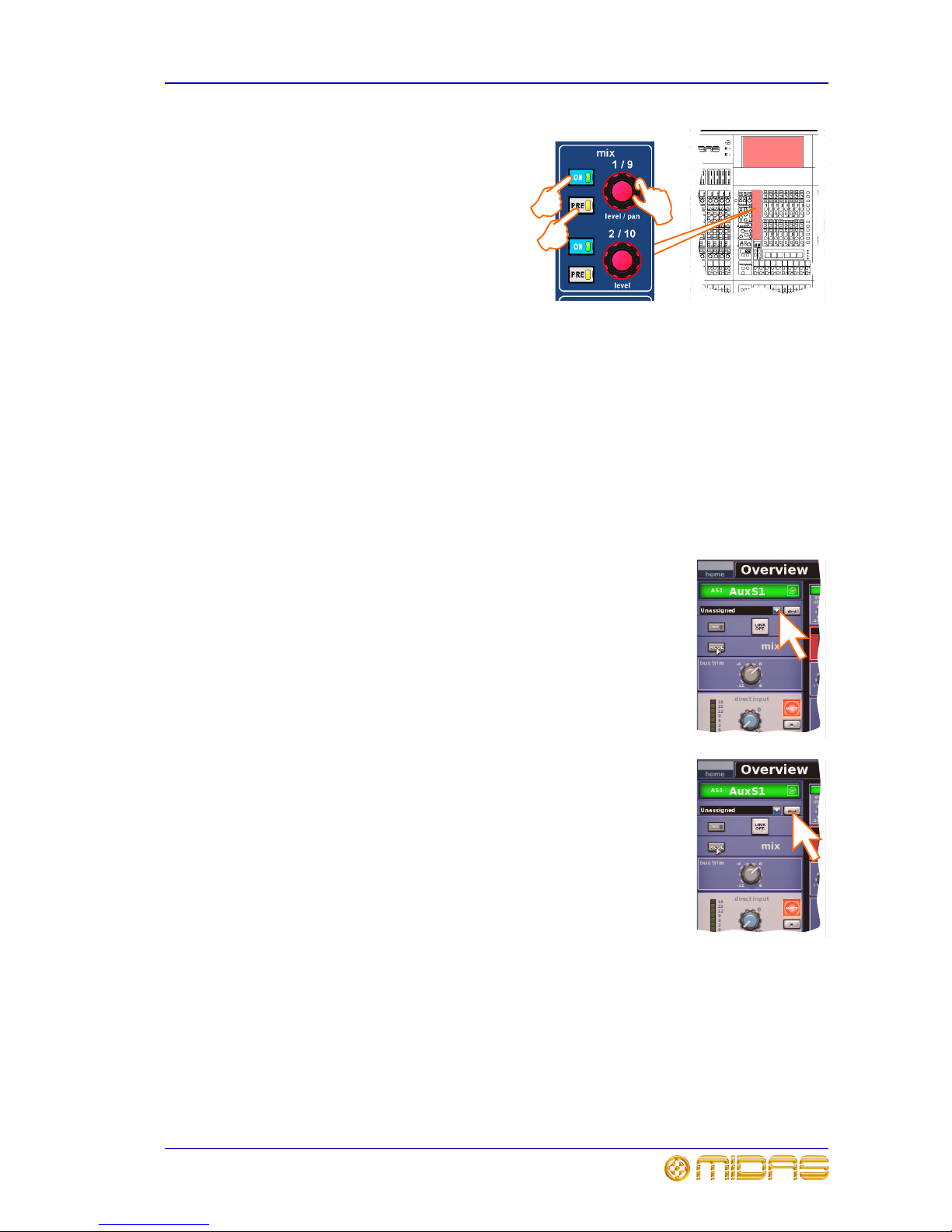
Setting up a mix 43
PRO6 Control Centre
Quick Reference Guide
4 In the mix (upper) section, do the
following:
• Press PRE to select pre-fader
(on) or post-fader (off). Button
status is only available on the
GUI (see Figure 10 on page 41).
• Press ON to route the aux mix
from input to aux output.
• Adjust the level control knob to
change the signal level. You
have the option to adjust them
using the pan/fader controls in the input fast zone (12-channel input bay);
this is known as “flip” mode. (You can also adjust them in the GUI channel
strip — overview or processing area — using drag.)
Mix bus routing
You can route an aux or matrix (or even master output) to an effect or output. This is
a GUI-only operation, which is done via the GUI channel strip or Patching screen (see
Chapter 5 “Patching”).
>> To route an aux or matrix to an effect or output
Do one of the following:
• In the processing area of the channel strip, click the required
mix bus destination from the drop-down list. For details of how
to open the processing area, refer to “To select the mix bus
mode” on page 42.
• In the processing area of the channel strip, click dest (shown
right). This will open the Patching screen and the appropriate
tab. For details of how to open the processing area, refer to
“To select the mix bus mode” on page 42.
•Open the Patching screen and route the aux/matrix from
there. For information on patching, see Chapter 6 "Basic
Operation" on page 31.
Linking
You can link two mixes together. Pairs can only be created from adjacent mix buses of
the same colour. To link a pair of mix buses, click the LINK button of the lower (odd)
numbered mix bus (even numbered mix buses do not have a LINK button). The LINK
button can found in the GUI channel strip (refer to “To select the mix bus mode” on
page 42). You can choose linking options for the pair after pressing the adjacent
LINK OPT. button.
a
b
c
Page 58

44 Chapter 6: Basic Operation
PRO6 Control Centre
Quick Reference Guide
Setting up the effects rack
You can set up the effects rack (in the GUI’s Effects screen)
to contain any of the available effects listed in the Change
Device Type window, in any of the eight rack positions.
This is a GUI-only function. The diagram right shows the
rack populated with the seven available effects.
The assignable controls panel (shown in the Delay
diagram below) is common to all effects, and allows you to
control effects parameters via the equivalent panel on the
control surface (master bay).
Delay — provides simple delay
line-based effects. Delay times can
be specified manually or you can use
the ‘tempo-tap’ button. It has a
three-mode delay algorithm: one
delay tap (mono or stereo
processing); dual - two delay lines
(stereo inset only); and ping-pong two delay lines with cross feedback.
DN780 — is a reverberation device
that emulates the Klark Teknik
DN780 Digital Reverberator/
Processor unit and allows you to
create unique acoustic environments
of virtually any type.
Flanger — has one or, if configured
as stereo, two-tap delay lines. One
tap is fixed and the other tap
position is modulated to provide
‘thru-zero’ flanging or single tap
modulation when ‘thru-zero’ is off.
Phaser — has one, or if configured
for dual operation, two stereo
phasers connected in serial or
parallel, according to mode setting.
Pitch Shifter — has two
independent channels that can
independently shift the pitch of
signals up or down to correct poor
pitching or generate harmonies. The
pitch change can also be modulated
as an effect.
SQ1 Dynamics — is an emulation
of the Klark Teknik Square ONE
Dynamics, which is an 8-channel
analogue dynamics processor. Used
for the precise manipulation of
compression parameters, it also
includes gating for creative and
corrective applications, and channel
linking for stereo/multi-channel
operation.
Page 59

Setting up the effects rack 45
PRO6 Control Centre
Quick Reference Guide
3 Band Compressor — is a
minimum phase shift (analogue
style) implementation that
guarantees coherent band summing,
even at the most extreme crossover
point settings. Each band provides
full control of its compressor’s
action, with partially adaptive time constants ensuring the most natural results from
even the most variable sources.
>> To add an effect to the effects rack
1 At the GUI, choose homeRack
UnitsEffects. Alternatively, press the
effects/graphics screen access button in
the primary navigation zone.
2 Cl ick wi thi n yo ur c hosen rac k po sit ion. T his
will be the position of the new effect.
3 In the new effect’s window, click CHANGE
DEVICE TYPE.
4 In the Change Device Type window, click
your chosen device type. For example,
“DN780”.
5 Click OK.
6 Change the parameters of the new effect
device, as necessary. For example, adjust
control knobs, press buttons etc. You can
even change the effect’s name by editing
its name field (shown above).
7 Click OK to exit. The new effect will appear
in the effects rack.
8 You can now patch the new effect, which
will be on the Effects tabs of both the
From and To sections of the Patching
screen. For information on how to patch,
see Chapter 5 "Patching" on page 23.
2
3
4
7
5
Effect name field
Page 60
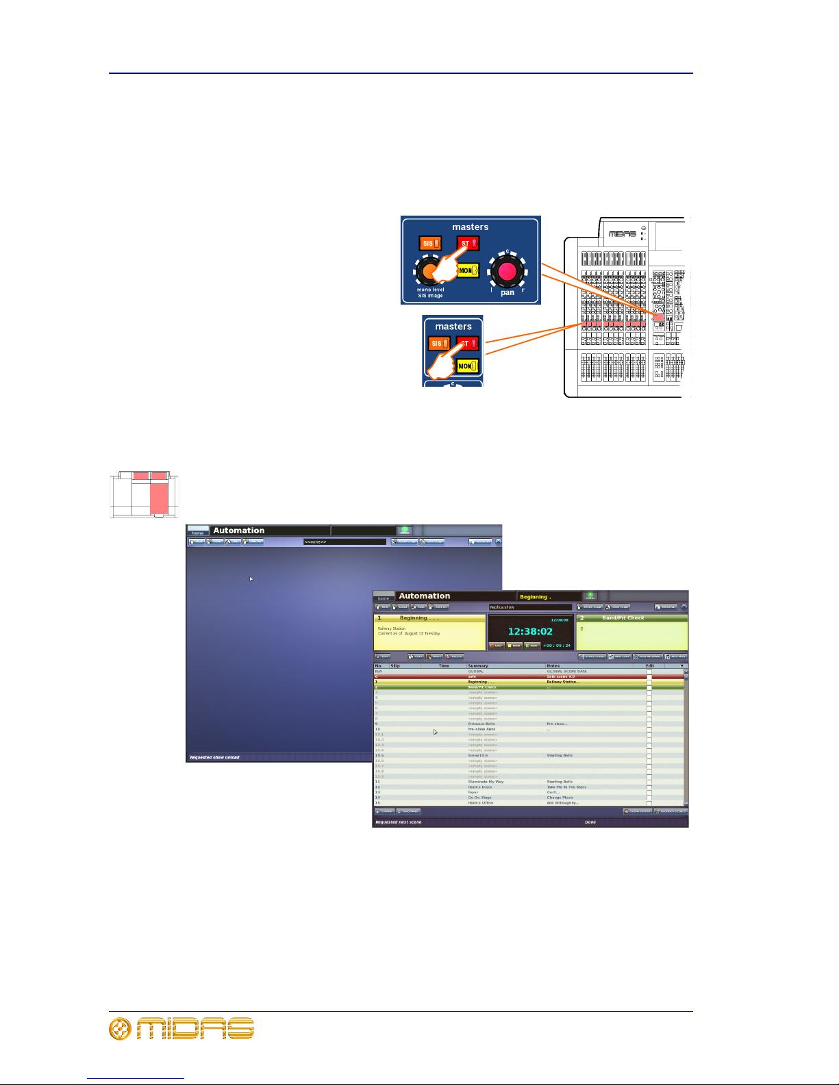
46 Chapter 6: Basic Operation
PRO6 Control Centre
Quick Reference Guide
Simple routing to master stereo outputs
The following shows you how to obtain audio. Before proceeding with this operation,
make sure nothing is muted and master faders are up.
>> To obtain audio
Do one of the following:
• Press the ST (stereo) button of
an input fast strip.
• Press the ST (stereo) button of
a channel strip.
Scene and show management (automation)
Automation allows you to manage show files and the scenes within the shows. This is
all done via the Automation screen (a GUI menu option). Figure 11 (below) shows
typical Automation screen displays before (left) and after a show is loaded.
Figure 11: Typical Automation screen displays
>> To access the Automation screen
Do one of the following:
• At the GUI, choose home
AutomationAutomation.
• In the primary navigation zone, press the automation/filing screen access button.
Page 61

Scene and show management (automation) 47
PRO6 Control Centre
Quick Reference Guide
Managing the shows
The four buttons (NEW, LOAD, SAVE and SAVE AS) towards the top of Automation
screen allow you to create a new show, load an existing show, update the current show
or create a new show using the current settings.
Important:
We recommend that you save your show
settings regularly (see “Saving a show
versus storing a scene” on page 33). The
PRO6 will indicate that there are show
settings to be saved by changing the
background colour of the SAVE button to
red.
>> To create a new show
1 Click NEW.
2 In the Enter new show name: window, type
your chosen name for the new show.
3 Click OK. You can now create
and manage the scenes for your
new show. (Clicking CANCEL
instead of OK will close the
Enter new show name:
window without creating a new
show.)
>> To save a show or create a new one from the current settings
Do one of the following:
• To update the current show with the latest settings, click SAVE.
• To create a new show using the current show
settings, click SAVE AS. Then, in the Save
File window, type in the name of the new
show. Click OK to save the new show and
close the window. (Clicking Cancel will close
the window without saving the new show.)
Page 62
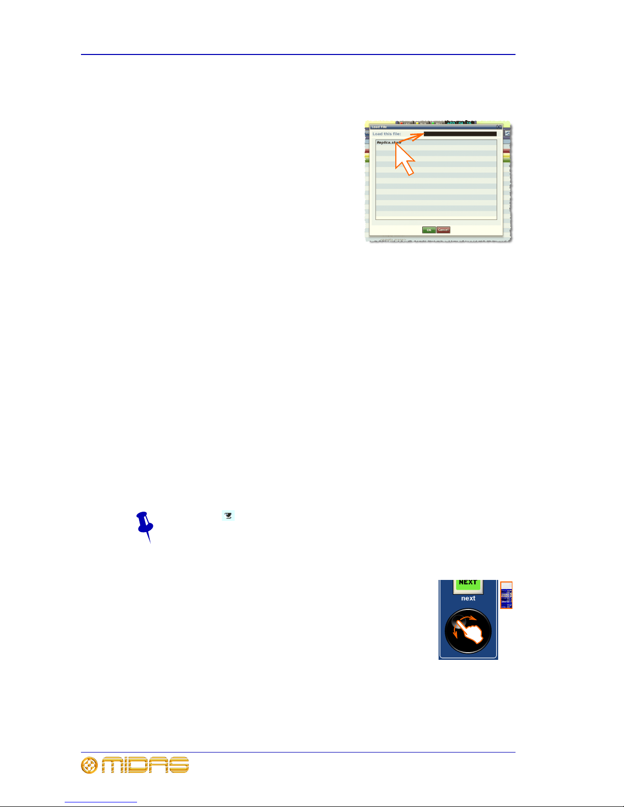
48 Chapter 6: Basic Operation
PRO6 Control Centre
Quick Reference Guide
>> To load a show
1 Click LOAD.
2 In the Load File window, click the show file
you want to load (shown right). The file
name will appear in the Load this file:
name field.
The Load File window will contain a list of
all the shows currently loaded. If the one
you want is not there, load it from a USB
memory stick (see “To load (import) a show
file from a USB memory stick” on page 56).
3 Click OK to start loading the file and close
the window. The show file name will appear
in the show file name field (next to the
SAVE AS button) when it has finished
loading.
Managing the scenes
An automation section in the master bay (see item H in Figure 2 “Main areas of the
control surface” on page 7) supports the Automation screen by providing a number of
controls for scene navigation and management. A jogwheel and a next LCD button are
unique automation controls, while the store, ok, cancel, last and now buttons are
replicated on the Automation screen.
The four coloured, backlit buttons are context-sensitive and illuminate only when they
are available. Typically, three scenes in the cue list (Automation screen) will be
highlighted to match the button colours (red, yellow or green) to show which scene
each button will act upon.
The jogwheel quickly scrolls through the individual scenes in either direction. You can
even go to the empty scenes towards the end of the cue list and then wrap to the
beginning. Operation of the jogwheel does not change scene selection.
The next LCD button displays information on the scene you have just scrolled to.
Additional function buttons on the Automation screen allow you to copy scenes and
also to choose what is stored within each scene (store and recall scope buttons).
The eye icon in the Automation screen (just under the ADD MIDI button)
opens a Show window, which contains a list of filter options.
>> To navigate the scenes using the jogwheel
Place a finger in the indent in the jogwheel and move it in a
clockwise or anti-clockwise direction, as required (shown right). The
scenes will be scrolled, one by one.
When using the jogwheel the next LCD button will illuminate yellow
and will track the scene currently highlighted in yellow in the cue
list. In this case, pressing this button will only have an affect if a
non-empty scene is currently highlighted.
Page 63
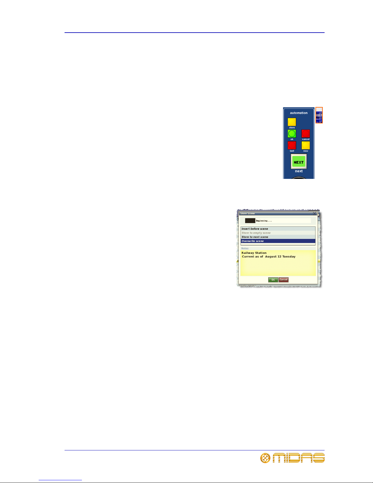
Scene and show management (automation) 49
PRO6 Control Centre
Quick Reference Guide
>> To recall a scene
Important:
When recalling a new scene, make sure monitor output levels are low, as the
new scene’s settings may produce higher audio output levels than the one it is
replacing. Also, recalling a scene clears any unsaved adjustments made to the
previous scene.
Do one of the following:
• Press last to change scene selection to the one currently
highlighted in red in the cue list, which was the last selected
scene.
• Press now to change scene selection to the one currently
highlighted in yellow in the cue list.
• Press next (LCD button) to change scene selection to the one
currently highlighted in green in the cue list, which is the scene
immediately following the ‘now’ scene. However, if you have used
the jogwheel the affect will be different (see “To navigate the
scenes using the jogwheel” on page 48).
>> To create a new scene using the current settings
1 Press STORE SCENE.
2 In the Store Scene window (shown right),
type in the scene name, if required.
3 In the Notes panel, type in any scene notes,
as required.
4 Do one of the following. The options are
context-sensitive, so some may be
greyed-out to show that they are
unavailable.
• Click “Insert before scene” to put the new
scene in between the one currently
highlighted in yellow and the scene
immediately before it.
• Click “Store to empty scene” to put the new scene in the one currently
highlighted in yellow, provided it is empty.
• Click “Store to next scene” to put the new scene in the next one, provided it is
empty.
• Click “Overwrite scene” to overwrite the scene currently highlighted in yellow.
An OK button will appear at the bottom of the window, to the left of the Cancel
button.
5 Click OK. This will store the scene, saving any changes you have made, and
close the window. (Clicking CANCEL will close the window, ignoring any
changes.)
Page 64

50 Chapter 6: Basic Operation
PRO6 Control Centre
Quick Reference Guide
Additional control — managing events
You can use the MIDI or GPIO functions of the PRO6 to control the parameters of an
external device (outgoing), and conversely you can use an external device to control
the PRO6 (incoming). Also, by using the PRO6’s unique ‘internal’ event option, you can
trigger events from within the showfile itself. All this is done by creating events in
scenes/point scenes.
You can have any number and types of events in any scene/point scene, and event
parameters are set up and edited in an Edit Event window. Similarly to scenes/point
scenes, you can skip events during rehearsals.
To aid event management, a menu appears (shown right) when you
right-click a scene/point scene or event. The menu options allow you to
create, edit and copy events. Click an option to select it.
The following shows what some of the event symbols in the Automation
screen mean: = currently selected event; = MIDI event;
= GPIO event; = internal event; = incoming event; and
= outgoing event.
>> To create an event
Select the scene in which you want to create the event, and then do one of the
following:
• Click the ADD GPIO, ADD INTERNAL or ADD MIDI button, as required.
• From the ‘right-click’ menu, choose Add
Midi Event, AddInternal Event or
Add
GPIO Event, as required.
>> To edit an event
1 Right-click the event you want to edit, and then
choose Edit to open the Edit Event window (a
typical example is shown right).
2 In the Edit Event window, choose your options
as necessary. For example, you can use a
program change to trigger the event.
3 At the upper-right corner of the Edit Event
window, click “X” to close it.
>> To copy and paste an event
1 Right-click the event you want to copy, and then
choose Copy from the menu.
2 Select the scene in which you want to paste the
copied event. Or, if the scene already contains an
event(s), select the event after which you want to
paste the copied event.
3 Right-click to open the menu, and then choose
Paste.
Page 65

Configuring the inputs and outputs 51
PRO6 Control Centre
Quick Reference Guide
Configuring the inputs and outputs
Similarly to the VCA/POP groups, you can change the name and colour of each of the
inputs and outputs. This is done via the GUI at their respective sheet screens. For
configuration details, see “Configuring the VCA/POP groups” on page 40.
>> To open the Input/Output Sheet screen
Do one of the following:
• At the GUI, choose homeInput ChannelsInput Sheet to open the
Input Sheet screen, or choose home
Mix & OutputsOutput Sheet to open
the Output Sheet screen.
• In the primary navigation zone, press the inputs/outputs screen access button
once to open the Input Sheet screen or twice in quick succession to open the
Output Sheet screen.
Using copy and paste
The copy and paste buttons (upper-right corner of GUI) allow you to copy the
parameters of one/all of a single channel’s processing area(s) — such as the EQ,
compressor, gate etc. — and paste them to one/all of the other channels of a similar
type.
Right-clicking the copy or paste button will open their respective menu, each of which
contains full copy/paste options.
>> To copy a processing area to a channel/all channels
1 If necessary, navigate the channel’s processing area to the channel strip (see
“Navigating a processing area or mix bus to a channel strip” on page 22).
2 Click copy.
3 Do one of the following:
• To copy the processing area to another channel, select the channel and then
click paste. (As the copied parameters are still stored, you can paste to as
many channels as you want.)
• To copy the processing area to all other channels, right-click paste to open its
menu and then choose Paste To All.
>> To copy all parameters to a channel/all channels
1 If necessary, select the channel from which you want to copy all of the processing
areas.
2 Right-click copy to open its menu, and then choose Copy All.
Page 66

52 Chapter 6: Basic Operation
PRO6 Control Centre
Quick Reference Guide
3 Do one of the following:
• To copy the parameters to another channel, select the channel and then click
paste.
• To copy the processing area to all other channels, right-click paste to open its
menu and then choose Paste To All.
Copy and paste rules and restrictions
• You can only copy and paste similar functions. For example, you can’t copy the
input EQ from one channel to the output EQ of another, as they are different.
• You can only copy and paste across similar channel types. For example, you cannot
copy from an aux and paste to a matrix.
• Copying and pasting across inputs is restricted to the input bays only.
• Compressor settings can be copied, but not the mode (that is, corrective, adaptive,
creative, vintage or shimmer). To ensure mode similarity between source and target
channels, make sure the target channels have the same selected mode as the
source channel’s before copying.
• Channel names are not copied.
• Compressor and gate side chain listen cannot be copied.
• Auxes: mix pan and master routing direct input solo B GEQ all parameters can be
copied, but insert cannot be copied.
• Returns: mix pan and master routing solo B can be copied.
• Matrices and masters: mix pan and master routing direct input solo B GEQ all
parameters and fader area solo B can be copied.
Show editor
The show editor is a GUI-only
function that allows you to
very easily copy and paste
settings through scenes. This
is done via the Show Editor
screen (shown right).
The panel on the far left of the
Show Editor screen shows
the sources (channels, GEQs
and effects) from which you
can copy the settings. The
Sections panel in the centre
of the screen contains source
sections that you can copy to
the scene(s). At the far right
of the screen is the Scenelist
panel, which is a cue list of the
current show.
>> To open the Show Editor screen
Do one of the following:
• From the GUI menu, choose home
AutomationShow Editor.
• At the Automation screen, click SHOW EDITOR.
Page 67

User library 53
PRO6 Control Centre
Quick Reference Guide
>> To copy and paste sections to a scene(s)
1 In the Show Editor screen, click the sources that contain the sections you want
to copy to a scene(s). These are in the far left panel of the screen. You can
choose any combination of inputs, aux returns, aux sends, matrices, GEQs,
effects and masters.
2 In the Sections panel, click the boxes of the sections that you want to copy.
Ticked options will be copied.
3 In the Scenelist panel, click the scene(s) in which you want to paste the
sections. You can use the buttons at the bottom of the list to help you, as
follows:
• Click ALL to select all of the scenes in the list.
• Click NONE to deselect all selected scenes.
4 Click PASTE TO SCENES.
5
User library
The PRO6 has a user library where you can store
settings, such as for the EQ or the whole channel. For
example, you may wish to store the EQ settings of a
singer who may be called upon to perform during a
future show. You can then easily recall these EQ
settings to the appropriate channel, when required.
The settings are stored as presets, which along with the
library files, are managed via a Preset Manager
screen on the GUI. Here, you can create new libraries,
load existing libraries, save the current library or give it
a new name. You can also delete presets from the library.
>> To open the Preset Manager screen
From the GUI menu, choose home
Preset Manager.
>> To save a preset to the user library
1 Make sure that the settings you want to save are assigned to the channel strip,
then click store preset. If the channel’s overview is displayed, all of its settings
will be saved in the preset. Otherwise, just the settings of the displayed
processing area will be saved.
2 In the Save Preset window (shown right), type in
your chosen preset name (Preset Name), your
name (Preset Author) and any note (Notes) as
necessary.
3 Click OK.
>> To load a preset
1 Make sure that the channel in which you want to
load the settings of the preset is assigned to the
channel strip, then click load preset.
2 In the Load Preset window, click the preset that you want to load.
3 Click OK.
Page 68

54 Chapter 6: Basic Operation
PRO6 Control Centre
Quick Reference Guide
Surround panning
In addition to stereo and LCR panning, the
PRO6 has three surround panning modes:
quad; left, centre, right and surround
(LCRS); and 5.1 surround. These are
operated via a surround monitoring system,
which uses matrix channels 1 to 6 as the
surround bus channels. The channels are
muted via six MUTE buttons in the master
bay. PRO6 output connections are via the
surround, sub, centre and front XLRs on
the rear panel.
The 5.1 panning mode uses all six
channels, while quad mode uses four (left
and right on both the front and surround).
Al thou gh the LCRS mode u ses f ive c h anne ls
(front left and right, centre and surround
left and right), both surround channels are
the same.
The surround panning mode is selected via
the Preferences screen of the GUI menu (home
PreferencesGeneral), which
contains a list of the surround panning mode options under the Surround Mode heading.
The diagram above right shows the areas on the control surface associated with
surround panning and the matrix channel allocation of the surround monitoring
system’s MUTE buttons. Figure 12 shows the allocation of the surround MUTE buttons
per loudspeaker, and the recommended
1
5.1 surround system configuration.
Figure 12: 5.1 surround panning arrangement
1. Reference - ITU-R BS.775.1, 1994. Multichannel stereophonic sound system with and without
accompanying picture. International Telecommunications Union.
Matrix channels
12 3 4 56
Subwoofer
Front left
Centre
Front right
Rear right
(right surround)
Rear left
(left surround)
30°30°
110° ±10°
110° ±10°
Listening
distance
Loudspeaker
Page 69

Two-man operation 55
PRO6 Control Centre
Quick Reference Guide
Two-man operation
The PRO6 Control Centre can be operated by two people simultaneously. In this mode
of operation the 4-channel input bay is designated as area B, and operates
independently of the 12-channel input bay, which is always area A. (You can have the
same channel selected simultaneously in both bays.)
This feature can also be used by a single operator if they require somewhere to
store important channels. In this case, area B can be used in the same way a
‘channel 25’ would be used on an analogue console.
The following diagram shows the areas designated as A and B during two-man
operation and also shows the location of the area B button. All other parts of the
control surface are common to both areas.
Figure 13: Two-man operation
Groups can be pre-selected to populate area A or B, and a single group of inputs can
have members in both areas of the control surface. An operator can then recall them to
their own area to work on.
Note: When operating in area B, please remember to select the B option, where
appropriate, particularly in the monitor section. Also note that solo B (also for talkback)
is totally independent of area B, which is used for navigation only.
>> To set up the PRO6 Control Centre for two-man operation
In the input select section of the master bay, press B (see Figure 13 above).
Area A
Area B
Page 70

56 Chapter 6: Basic Operation
PRO6 Control Centre
Quick Reference Guide
Saving your show files to USB memory stick
When you are satisfied that your show file is how you want it, we recommend that you
save it to a removable storage device (USB memory stick). This provides a valuable
back up should the show file stored in the internal memory of the PRO6 be lost, for
example, due to inadvertent deletion or in the highly unlikely event of system failure.
You can also load show files onto the PRO6 from the same storage device.
>> To save (export) a show file to a USB memory stick
1 Insert the USB memory stick
into the active USB socket,
which is the one with the
flashing active LED. For
example, USB key 2 (shown
right).
2 Do one of the following:
• At the GUI, choose
home
Files.
• In the primary navigation
zone, press the
automation/filing screen
access button twice in
quick succession.
3 You may see an “Analysing...” message
in the Removable Storage panel,
which means that the Midas folder on
the USB memory stick is being read.
Wait for the message to clear. Then, in
the Control Surface panel, click the
show file you want to copy (shown
right).
4 Click EXPORT.
5 In the Are You Sure you Want To
Export? message window, click OK. The file will
start copying to the USB memory stick.
6 When your show file appears in the Removable
Storage panel, it has finished copying to the
USB memory stick. Remove the USB memory
stick
>> To load (import) a show file from a USB memory stick
The procedure is similar to the export procedure, as detailed in “To save (export) a
show file to a USB memory stick” on page 56, but select the file to be imported to the
PRO6 from the Removable Storage panel and then press IMPORT.
USB memory
stick
Page 71

PRO6 Control Centre
Quick Reference Guide
Volume 1:Connecting And
Setting Up The
System
Page 72

Page 73

59
PRO6 Control Centre
Quick Reference Guide
Chapter 7: Setting Up The System
This chapter shows you how to set up a PRO6 Live Performance System to its default
configuration.T
Note: If you want to set up the PRO6 Live Performance System using a configuration
other than the default, please contact Midas Technical Support for details.
Initial set-up procedure
Initial system set-up basically comprises:
• Unpacking and checking the equipment — see “Unpacking the equipment” on
page 59.
• Making up a rack — see “Making up a rack” on page 59.
• Connecting up the equipment — see “Wiring instructions” on page 59.
• Powering the equipment — see “Powering the PRO6 system” on page 61.
• Initial patching — see “Setting up the I/O rack devices” on page 27. It is
important to set up the type of snakes connected in the system.
• Configuring the DL351 unit — see “Setting up the DL351 Modular I/O unit ID” on
page 63.
Unpacking the equipment
After carefully unpacking the equipment, check it against the packing list shown in
“System components (standard supply)” on page 4.
Save all packing materials, as they will prove useful should it become necessary to
transport the equipment later.
Inspect the equipment carefully for any sign of damage incurred during transportation.
It has undergone stringent quality control inspection and tests prior to packing and was
in perfect condition when it left the factory. However, if the equipment shows any signs
of damage, notify the transportation company without delay. Only you, the consignee,
may institute a claim against the carrier for damage during transportation.
Making up a rack
In the standard supply, the rack supplied with the PRO6 Live Performance System is
fully fitted with the DL351 Modular I/O and DL371 DSP units.
Wiring instructions
Connect the snake (copper or fibre optic) to the DL371 DSP unit and PRO6 Control
Centre (see Figure 14 “Standard system configuration” on page 60).
The DL351 Modular I/O and DL371 DSP units should already be connected together
when you receive them.
Page 74

60 Chapter 7: Setting Up The System
PRO6 Control Centre
Quick Reference Guide
Figure 14: Standard system configuration
DL371 DSP
(4 x AES50
expansion ports)
Rack (the DL351 and
DL371 units are
typically located in a
single 14U rack)
Maximum 100 m,
typically 0.5 m
(N+1 redundant
AES50)
Dual cable redundant HyperMAC
(fibre optic or copper)
PRO6 Control Centre
(control surface, router, 8 x inputs,
8 x outputs, 8 x insert Jack I/Os and
6 x monitor outputs)
DL351 Modular I/O
(56 x inputs and
8 x outputs)
Copper
Fibre optic
Mix position
Stage
3 x AES50 expansion
ports
Page 75

Powering the PRO6 system 61
PRO6 Control Centre
Quick Reference Guide
Powering the PRO6 system
The following details the recommended power up and power down procedures for the
PRO6 system.
Note: If you are in any doubt as to how to switch the DL3n1 units on/off, refer to their
operator manuals.
>> To power up the PRO6 system
Important Note:
DO NOT switch on the speaker sub-system until after the start-up of the PRO6
system has been completed.
After all PRO6 system interconnections have been made (refer to Figure 14 “Standard
system configuration” on page 60), start up the PRO6 system:
1 Make sure that all of the PRO6 system equipment is switched off, that is, the
PRO6 Control Centre, speaker sub-system, DL351 Modular I/O unit and DL371
DSP unit.
2 Switch on the PRO6 Control Centre (see “To switch on the PRO6 Control Centre”
on page 62).
3 In the master bay of the PRO6 Control Centre, move all of the monitor and
master channel faders to the minimum position and mute all of the master
channels (see section F in Figure 2 “Main areas of the control surface” on
page 7).
4 Switch on the DL351 Modular I/O unit.
5 Switch on the DL371 DSP unit.
6 After both status indicators at the top of each GUI screen
have changed to green (as shown right), switch on the
speaker sub-system.
7 Switch on the audio source and start playing the audio.
8 On the PRO6 Control Centre, check that the audio inputs are routed to the master
channels. Then, unmute the master channels and gradually increase their faders
while listening to the sound levels from the speakers.
If there is no sound at all coming from the speakers when the faders are at maximum,
move the faders to below the 0dB level and check if the audio is muted somewhere
along the input paths and also check that the individual speakers are switched on. If
there is still no sound from the speakers, see “No audio” on page 67.
>> To power down the PRO6 system
Important Note:
BEFORE switching off any of the PRO6 system components, don’t forget to
mute the audio from the speakers and switch off the speaker sub-system.
1 Mute the audio from the speakers and switch off the speaker sub-system.
2 Switch off the DL351 Modular I/O unit.
3 Switch off the DL371 DSP unit.
4 Switch off the PRO6 Control Centre (see “To switch off the PRO6 Control Centre”
on page 62).
Page 76

62 Chapter 7: Setting Up The System
PRO6 Control Centre
Quick Reference Guide
Switching the PRO6 Control Centre on/off
Carry out the following to switch the PRO6 Control Centre on or off in a safe manner,
observing all WARNINGS and Cautions.
>> To switch on the PRO6 Control Centre
Caution!
Before switching on, check that all monitor loudspeaker power
amplifiers are turned off or muted.
Caution!
A minimum of two power supply modules must be supplying power
to the PRO6 Control Centre for correct operation.
After connecting up the audio cables, carry out the following:
>> To switch off the PRO6 Control Centre
1 Make sure you have saved any shows, scenes or settings you require (see
“Saving your show files to USB memory stick” on page 56).
2 At the GUI, choose homeShutdown System.
3 At the Shutdown ENTIRE system? prompt, click OK.
4 After the shutdown sequence has finished, switch off the D.C. POWER switch
(rear of control centre).
5 Disconnect the mains cables from the rear of the PRO6.
Mains
plug
Mains
outlet
Rear of PRO6 Control Centre
1 Plug the three mains cables into the mains
power outlets.
2 Plug the IEC connectors of the three mains
cables into the mains sockets on the rear of
the control centre. (The green LED next to
each mains socket will illuminate if its
mains supply is on.)
3 Observing the Cautions above, apply
power to the PRO6 Control Centre by
switching the D.C. POWER switch on. The
PRO6 Control Centre will boot up (see
“Booting up” on page 63) and, when the
default GUI screens are displayed, it is
ready for use.
1
2
3
Mains power on/off
LED indicator
Page 77

Setting up the DL351 Modular I/O unit ID 63
PRO6 Control Centre
Quick Reference Guide
Booting up
The PRO6 Control Centre has two boot up modes, as follows:
• Cold: Cold boot occurs when a brand new system that has never before operated as
a system is booted up. Cold boot determines the system configuration and sets up
all the IP addresses and unit names.
• Hot: Hot boot is the normal mode of operation, even if the PRO6 has just been
loaded from a truck and is physically cold! Hot boot uses the configuration and
names stored in the system flash memory. A complete hot boot takes up to
approximately 30 seconds to complete. Should the configuration not match the
previously stored settings, the user is asked what action the PRO6 should take.
During boot up, you will briefly see the ‘splash’ screens on the GUI (also shown when
the PRO6 is locked), which is followed by the default screens. When these appear, the
PRO6 Control Centre is ready for operation.
Setting up the DL351 Modular I/O unit ID
After connecting up your PRO6 network system, you may need to set up the ID of the
DL351 Modular I/O unit, which is done via its control panel (see Figure 15 below). You
only need to this if the unit is not already configured to the ID you want, as there are
only two ID numbers available (1 and 2) and the default is ID 1. The unit’s ID number
is shown at the end of the bottom line in the default display, for example, the ID of the
unit shown in Figure 15 is “1”.
To change the ID number there is no need to switch on the PRO6 Control Centre, as the
procedure can be carried out offline.
Refer to the operator manual for the DL351 Modular I/O if you require more details.
Figure 15: Control panel of the DL351 Modular I/O (showing default display)
>> To set up the ID of the DL351 Modular I/O unit
1 Make sure the DL351 Modular I/O unit is switched on.
2 Press MENU and hold for approximately two
seconds to enter the main menu. You have
entered the main menu when the first option is
displayed.
3 Press the down arrow button to go to the set
ID option.
4 Press SELECT to go to the “Select ID” screen.
Page 78

64 Chapter 7: Setting Up The System
PRO6 Control Centre
Quick Reference Guide
5 Press the down arrow button to go to the ID 2
option.
6 Press SELECT to choose the ID 2 option.
7 Press MENU to exit menu mode.
Page 79

PRO6 Control Centre
Quick Reference Guide
Volume 2:Appendices
Page 80

Page 81

67
PRO6 Control Centre
Quick Reference Guide
Appendix A: Troubleshooting
This chapter gives a brief troubleshooting guide to the PRO6 Control Centre.
No audio
If you have set up the PRO6 and followed all of the instructions for obtaining audio, but
you are not hearing anything through the speakers, check the following:
• Make sure the appropriate ST buttons in the channel fast strips are on.
• Make sure the appropriate ST buttons in the source a/b panels (monitors section of
the master bay) are on.
• Make sure nothing is muted.
• Make sure no faders are set to minimum.
• Check that the VCA/group master faders are at unity gain.
• Use solo at selected points in the signal path to try and pinpoint where the signal is
being lost.
• Check for correct signal routing by making sure channel sources/destinations are
correctly assigned.
If you still don’t have any audio, contact Midas Technical Support.
Diagnostics
During operation you can view the Diagnostics screen (see Figure 16 below) to get an
overview of the current health and status of the system. The screen shows real-time
connectivity of the system and the health of connected nodes. In general, green items
are healthy and red ones indicate a problem. The Diagnostics screen also includes a
Swap button for changing the current network from X to Y, and vice versa. For more
information, see the PRO6 Control System Owner’s Manual.
Figure 16: Diagnostics screen
Page 82

68
PRO6 Control Centre
Quick Reference Guide
Swapping the active master controller
Although it is highly unlikely that the active master controller (MC) will develop a
malfunction, should it ever happen you will need to activate the standby MC.
>> To swap the active master controller
1 At the GUI, choose homeFiles.
2 Click FILE SYNC.
3 In the Master Controller File Synchronisation window, click the MAKE
ACTIVE button of the standby MC (shown in grey text). This will become the
active one.
Page 83

Thank you for reading through this Quick Reference
Guide. We hope you found it useful.
Please feel free to send us your comments.
Our contact details and website address can be found
at the front of this guide.
Page 84

Midas
Klark Teknik Building, Walter Nash Road,
Kidderminster. Worcestershire. DY11 7HJ. England.
Tel: +44 1562 741515, Fax: +44 1562 745371
Email: info@uk.telex.com
Website: www.midasconsoles.com
© 2008 Telex Communications (UK) Limited
 Loading...