

Midas Mida.Black 8, Mida.Black 10, Mida.Black 12, Mida.Black 14, Mida.Black 17 Installation Instructions Manual
...Page 1
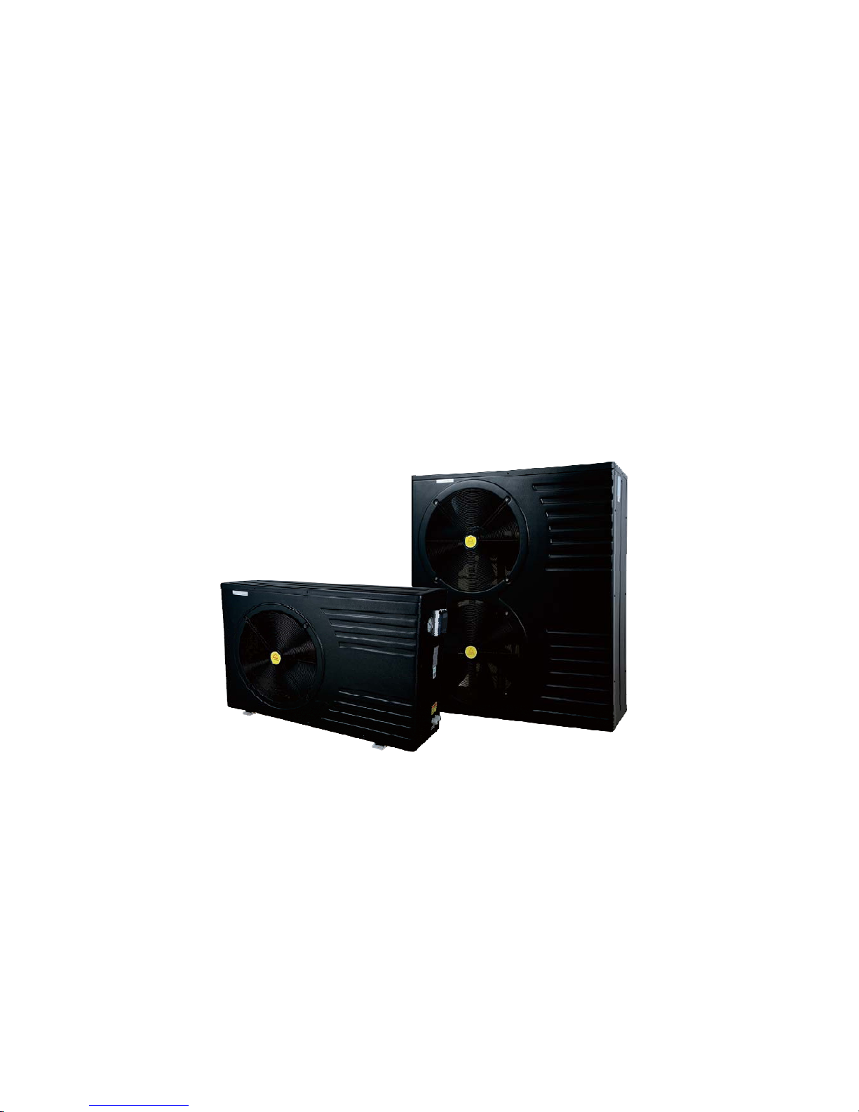
SWIMMING POOL HEAT PUMP UNITS
Installation&Instruction Manual
Rev. PG. EN&DE 04906
14.02.2017
1101-2720
Page 2

Page 3

ATTENTION:Thi s manua l inclu des all t he nece ssary i nfo rmation wi th the us e and the installation o f you r
heat pump.
The installer must read the manual and attentively follow the instructions in implementation and maint-
enance.
The installer is responsible for the of the product and should follow all the instructions of the manufact-
urer and the regulations in application. incorrect installation against the manual implies the exclusion of
the entire guarantee.
The manufacturer declines any responsibility for the damage caused with the people, objects and of the
errors due to the installation that disobey the manual guideline. Any use that is without conformity at t-
he origin of its manufacturing will be regarded as dangerous.
WARNING: Pleas e always e mpty the water in h eat pump dur ing win ter t ime or wh en the am bient temp -
erature drops below 0 C, or else the titanium heat exchanger will be damaged because of being frozen,
in su ch case , you w ill los e warranty on the h eat pump.
Please always cut the power supply if you want to open the cabinet to reach inside theWARNING:
heat pump due to high voltage electricity.
WARNING: Please keep the display controller in a dry area, or close the plastic cover to protect
the display controller from being defected by humidity.
Dear Customers,
Tha nk you for usi ng Midas pool heat pu mp .Ple ase read thi s instruct ion carefully b efo re th e installat-
ion and application of this product, otherwise it may lead to damage to the instrument or operators as
wel l as financial loss . When yo u might need f urthe r information p lease contact your local di str ibuto r. With
the gradual advancement of science and technology the product series and specifications will change as,
well, so you are invited to keep up with the latest products. In reading this instruction if you need any te-,
chnical consultations, contact your local distributor.
SWIMMING POOL HEAT PUMP UNITS
Installation&Instruction Manual
Page 4

Contents
1. Performance and installation
1.1 P erform ance an d featur es
1.2 Working principles
1.3 Specification
1.3.1 Technical data
1.3.2 Dimension
1.4 L ocati on of heat p ump ins talla tion
1.5 Distance from the pool
1.6 Installation of the check-valve
1.7 P ool syste m set up
1.8 Connecting the by-pass
1.9 Electrical hook-up
1.10 First time start-up
1.11 Condensation
1
1
3
5
5
1
2
2
4
6
6
7
8
8
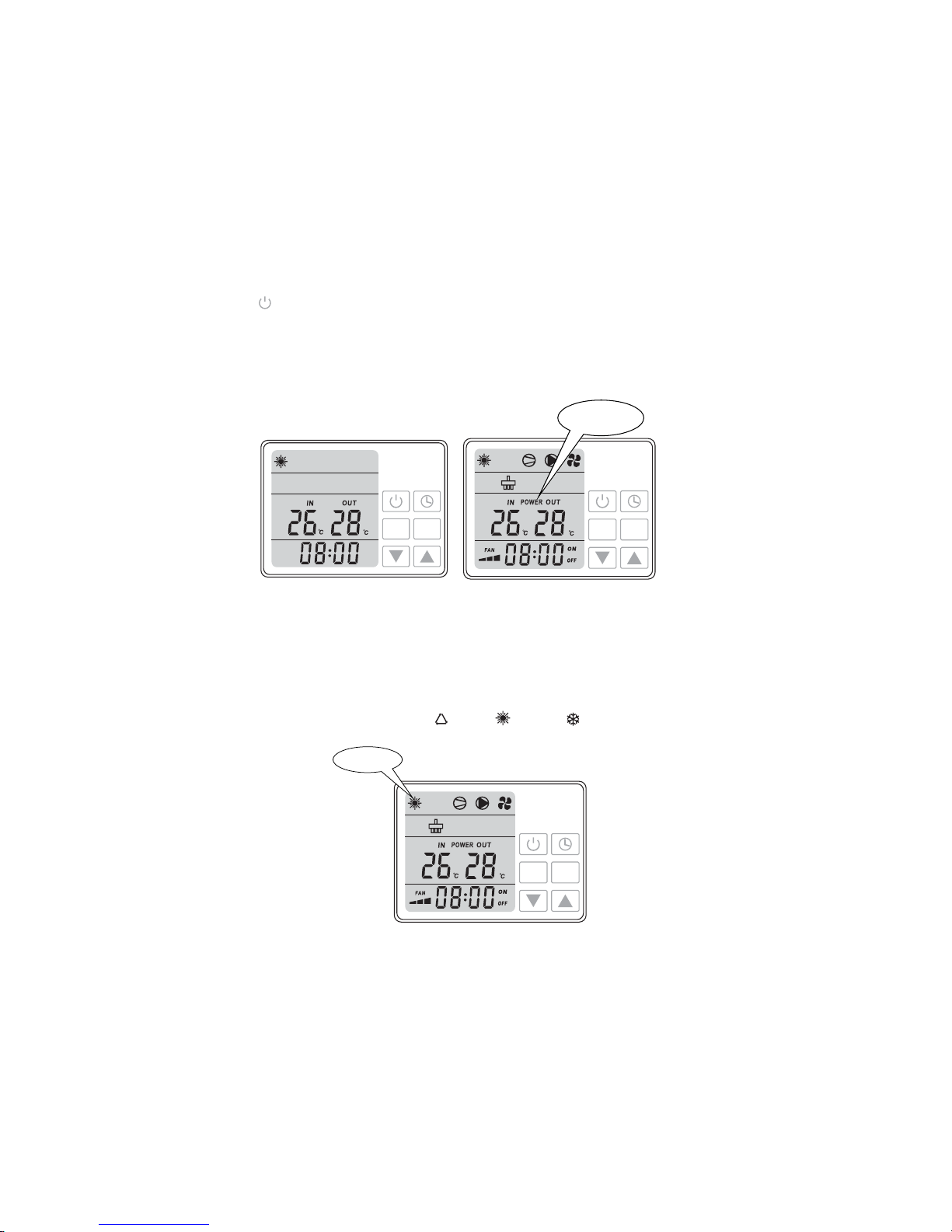
2.1 Controller illustration
2.2Power ON/OFF heat pump
2.3 H ow to cha nge mode
2.4 Adjust desired water temperature
2.5 C heck an d set para meter s
2.6 S etting Time
2.7 Param eter tab le over view
2.8 S etting Time r on/ Tim er off
2.9 Cancelling Timer on and Timer off
2.10 Key pad lock
2.Control of the heat pump ( New col or LED )
9
10
10
11
11
11
12
13
13
13
3. Protection systems
3.1 Water flow switch
3.2 R efrige rant gas h igh and l ow pres sure pro tecti on
3.3 Overheating protection on the compressor
3.4 A utoma tic defr ost cont rol
3.5 Temperature difference between inflowing and outflowing water
3.6 L ow temp eratur e cut-o ut
3.7 Anti-frost protection during winter
3.8 First anti-frost protection
3.9 Second anti-frost protection
14
14
14
14
14
14
14
14
14
4.1 Swimming pool water chemistry
4.2 Heat pump winterizing
4.3 R estart ing the p ump aft er winte r
4.4 Check-up
4.Direction
15
15
15
16
17
17
20
5.1 Maintenance
5.2 Trouble shooting guide
5.3 Fa ilure c ode tab le for plu g-in ty pe PCB
5. Maintenance and inspection
6.1Name plate
6.2 Wiring diagram
6.Name plate & wiring diagram
21
22
9
21
14
17
15
Page 5
1. Performance and installation
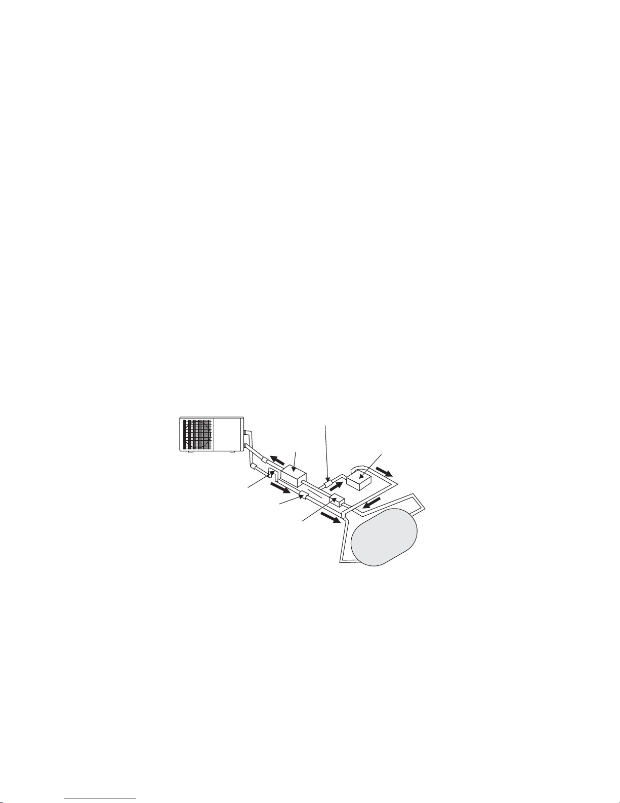
1.1 Performance and features
Cooler
De-energizedAir
War m
Air
Fan
Evaporator
(Energy Collector)
Capillary Tube
Condenser
(Water Heat Exchanger)
Pool Filter
Pump
Compressor
Swimming pool
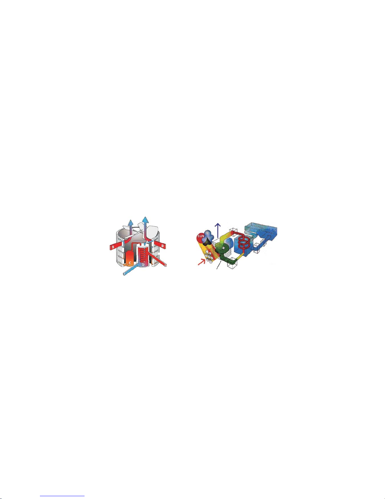
1.2 Working principles
√High efficiency
With aCOP valueup to 5.0our heat pumpsare very efficient when transferring heat from theair to
the swimmingpool water. Youcan saveas much as80% of costcompared toan electrical heater.
Long life-span√
The heat exchangeris made of PVC & Titanium tube, which can withstandand prolong exposure to
swimming pool water.
Easy√ control and operation
The u nit is ve ry easy to o perate : simpl y switch it on a nd set th e desired po ol water temperature.
The system includes a micro-computer controller, allowing all operation parameters to be set.
Operation status can be displayed on the controller with LCD display.
√Heat pumps utilize the sun s free heat by collecting and absorbing energy from the outside air. This'
ene rgy is then co mpressed and trans ferred to the p ool wat er. You r exis ting water pu mp c ircu lates the
water throu gh th e heater, usua lly nex t to th e pool eq uipme nt, and t he water warm s up. The heat p ump
tim er coul d be set to operate du ring dayli ght hou rs, for exa mple, u suall y 9am to 5pm.
The u nit contai ns a fan tha t draws in o utside air a nd directs i t ove r t he su rfa ce of the EVAPO RATOR√
(energy collector).The liquid refrigerant within the EVAPORATOR coil absorbs the heat from the
out side ai r becom es a ga s.
The w arm gas in t he coil p asses through t he COMP RES SOR con centratin g and i ncreasing the heat to√
form a ver y hot gas which the n passes to th e CON DENSE R (water heat exc hange r).It is here t hat t heheat
exchange occurs as the hot gas gives off heat to the cool swimming pool water circulatingthrough the coil.
The p ool water becom es wa rmer, and t he hot ga s coolin g as it flow s th roug h th e CONDENSE R coil ret-√
urns to its liquid form and, after passing on through the CAPILLARY TUBE the whole process begins again,.
7℃The state of the heat pump technology can efficiently collect heat from theoutsideair downto the to√
10 range . For t rop ic and subtropi cal c limates, t his means th at the po ol ca n be maintained at 26 to 32℃℃
Heat exchanger
Water flow out
Evaporator
Air flow
Compressor
Air flow
Water flow in
1
Figure 1-1
Figure 1-2
Page 6
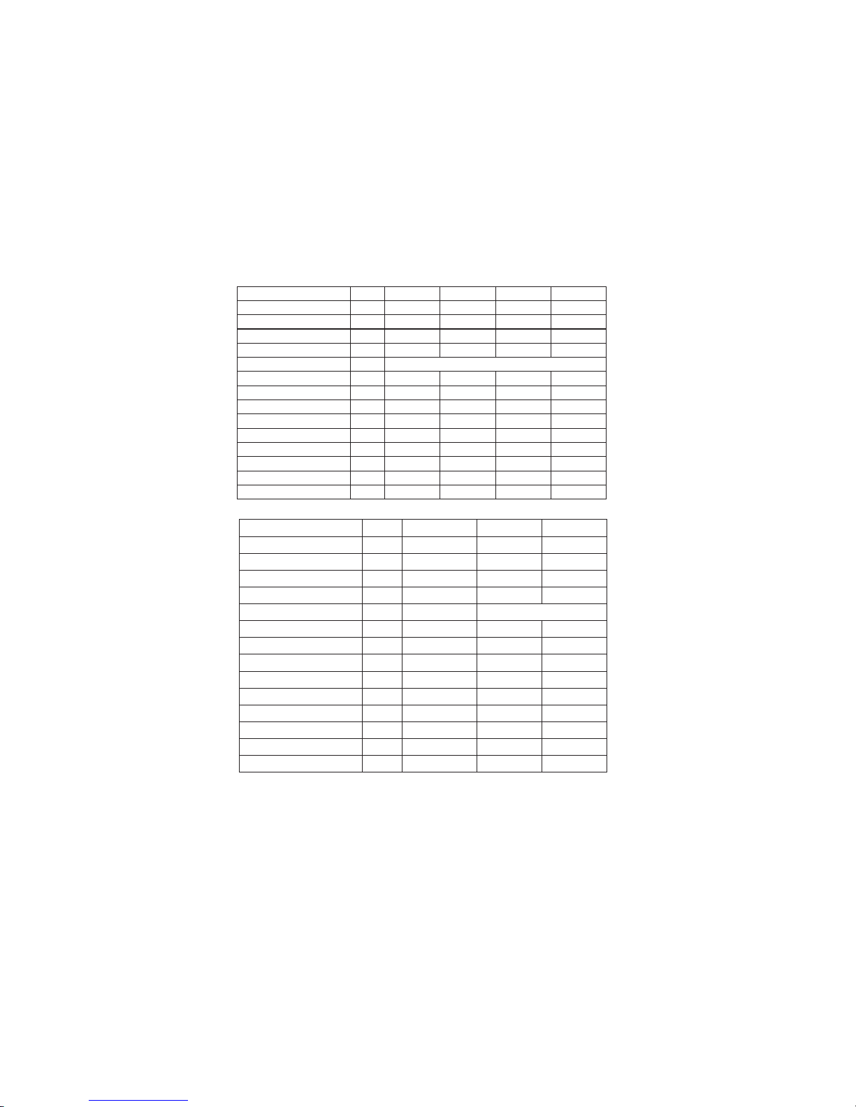
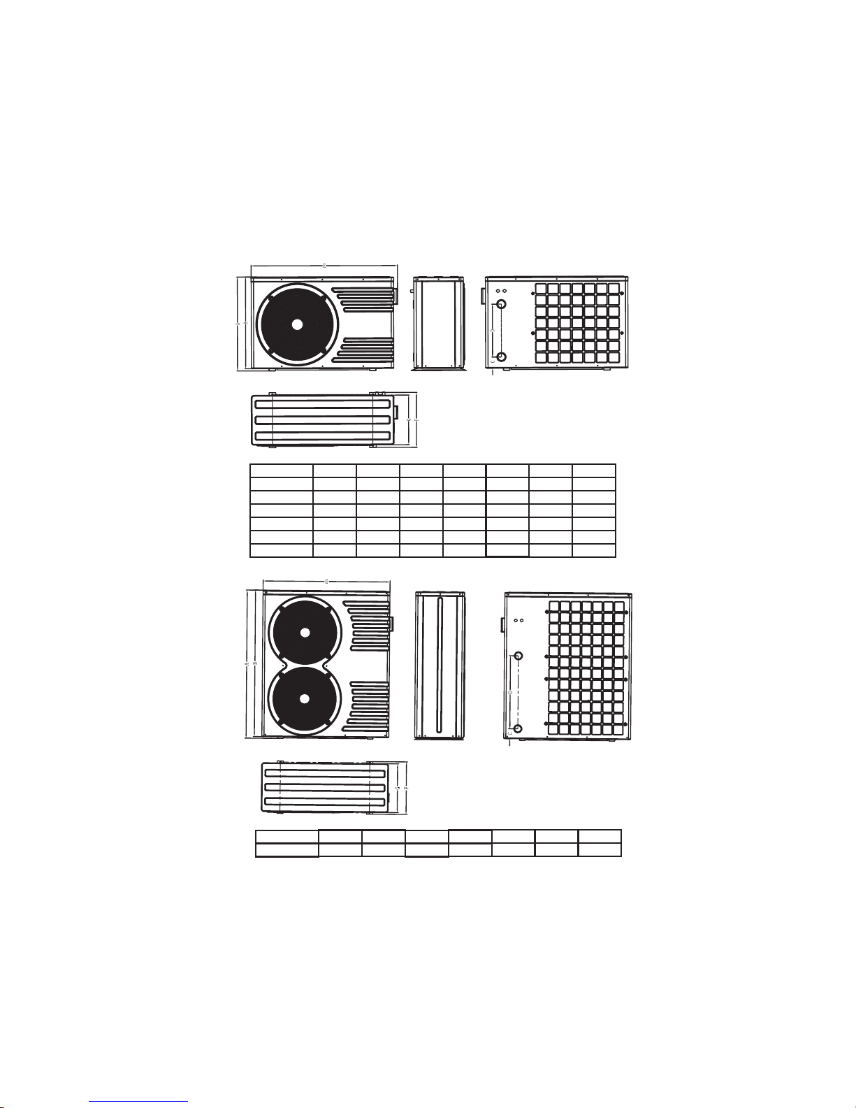
1.3 Specification
1.3.1 Technical data
2
*Data are subjects to modification without notice, data on nameplate of products are
of updated version.
Measuring conditions: Outdoor air temp: 24°C , Inflowing water temp: 26°C, rel. humidity: 65%
Mida Black 14.
14
2550
55.
11. 57
Rotating
120
850
43
50
7
14
1110 415 710**
81
220-240V/1PH/50HZ
Model
Heating capacity
Power input
Efficiency
Nominal current
Power supply
Compressor type
Fan power
Rotational frequency of the fan
Noise @10 meter
Water Connection
Nominal water flow
Max.water pressure drop
Net dimensions(L/W/H)
Gross weight
kW
W
C.O.P
A
V/Ph/Hz
w
RPM
dB(A)
mm
mh³/
kPa
mm
kg
Rotating
80
850
39
50
5
10
970 360 585**
55
Mida Black 10.
9.8
1730
565.
7.85
Rotating
120
850
42
50
6
12
1045 370 625**
62
Mida Black 12.
12.8
2360
545.
10.72
Rotating
120
850
42
50
7
12
1045 370 625**
67
Mida Black 26.
26
4480
58.
8.0
Scrolling
240*2
770
47
50
15
16
1110 445 1260**
137
380-400V/3PH/50HZ
Model
Heating capacity
Power input
Efficiency
Nominal current
Power supply
Compressor type
Fan power
Rotational frequency of the fan
Noise @ 10 meter
Water Connection
Nominal water flow
Max.water pressure drop
Net dimensions(L/W/H)
Gross weight
kW
W
C.O.P
A
V/Ph/Hz
w
RPM
dB(A)
mm
mh³/
kPa
mm
kg
Mida Black 17.
17
2790
6.1
13.3
Scrolling
240
770
43
50
10
14
1110 415 710**
99
Mida Black 21.
21
3620
58.
6.5
Scrolling
370
850
46
50
12
16
1110 445 960**
111
Mida Black 8.
.78
1440
.54
657.
220-240V/1PH/50HZ
Page 7

3
1.3.2 Dimension (mm)
Model
Mida. Black 8
Mida. Black 10
Mida. Black 12
Mida. Black 14
Mida. Black 17
Mida. Black 21
A
585
625
625
710
710
960
B
554
564
564
694
694
944
C
85
85
85
85
85
85
D
250
300
300
400
400
500
E
970
1045
1045
1110
1110
1110
F
360
370
370
415
415
445
G
313
340
340
386
386
420
Model
Mida. Black 26
A
B
C
D
E
F
G
1260
1244
85
620
1110
445
420
Page 8
1.4 Location of heat pump installation
The unit will perform well on any location provided three factors are present:
1. Fresh air 2. Electricity 3. Pool filter piping
The unit may be installed virtually anywhere outdoors providingminimum distance requirements aremet
with respect to other objects (see diagram below).For indoor pools please consult your installer. If the
uni t is plac ed in a win dy area, no probl ems occ ur with e .g. the pilot li ght, as o ppo-sed to w hat i s often the
cas e with gas heaters .
Do no t place t he unit i n an encl osed ar ea wi th a limi ted air volu me where the u nit'sAttention:
discharged air will be re-circulatedor near shrubs that could block the air inlet. These locati-
ons deny the unit a continuous fresh air supply, which reduces its efficiency and may prevent a-
dequate heat yield.
See diagram below for minimum required distances.
Cautions
√Do no t put you r hands or any othe r object into the a ir outl et and fan. It coul d damag e the heat pum p and
cause injuries.
In case any abnormality was found in the heat pump, please cut off the power at once andcontact a√
professional technician.
It is strongly suggested to place a guard around the machine to keep children away from the heat pump.√
4
Figure 1-3
Model:Horizontal Unit
Fre e space re quire ment for t he hori zontal h eat pum p
Not less than 500mm
Air in
Not less than 500mm from the top
Air in
Not less
than 500mm
Not less than 2000mm
Air o ut
Not less
than 500mm
Page 9
1 5 Distance from the pool.
Normally, the pool heat pump is installed within a 7.5 meter radius of the pool. The greater the distance
from the pool, the greaterthe heat loss from thepiping. Sincethe piping is buried forthe most part,
hea t loss is mini mal for dista nces of u p to 30 meters (15 meters to and from the p ump= 30 m eters to tal),
unless thesoil iswet orthe water levelis high.Heat lossper 30 meters could roughly be estimated at 0.6
kw-hour (2000BTU) for every 5 temperature difference between the pool water and the soil℃
surrounding the pipe which translates to an operation time increase of 3-5,%.
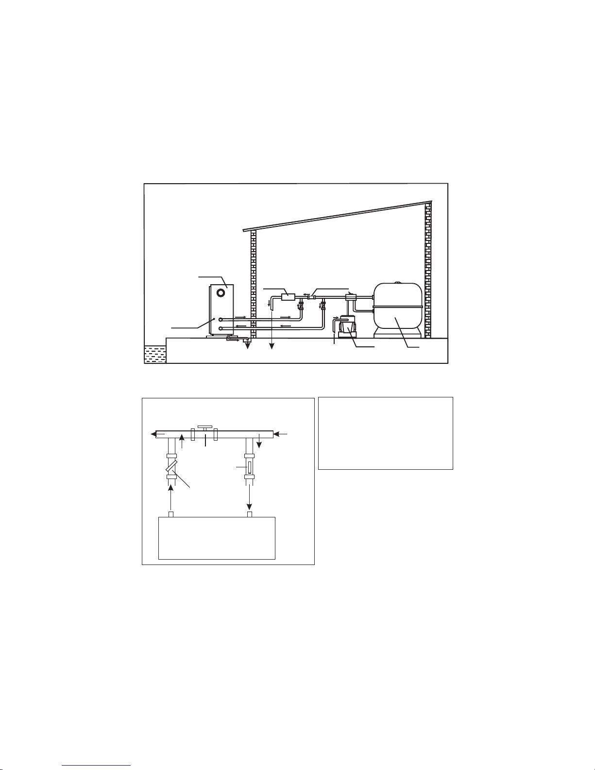
1.6 Installation of the check-valve
Attention- When using automatic chlorine and PH dosage systems, it is ofuttermost importanceto protect
the h eat pum p fro m high conce ntrations o f these c hemic als that could co rro de the heat exc hanger.
Therefore, such systems should add thechemicals in the conduits locatedDOWNSTREAM of the heat
pum p and it is r eco mmended to i nstall a c heck- valve in order to prevent back flow when th ere is no water
circulation.
Damage to the heat pumpcaused by disregardinganyof theserecommendations will invalidate the warranty.
5
Water Pu mp
P-trap
Filter
Chlorinator
Check-valve
Swimming Pool
Figure 1-4
Page 10
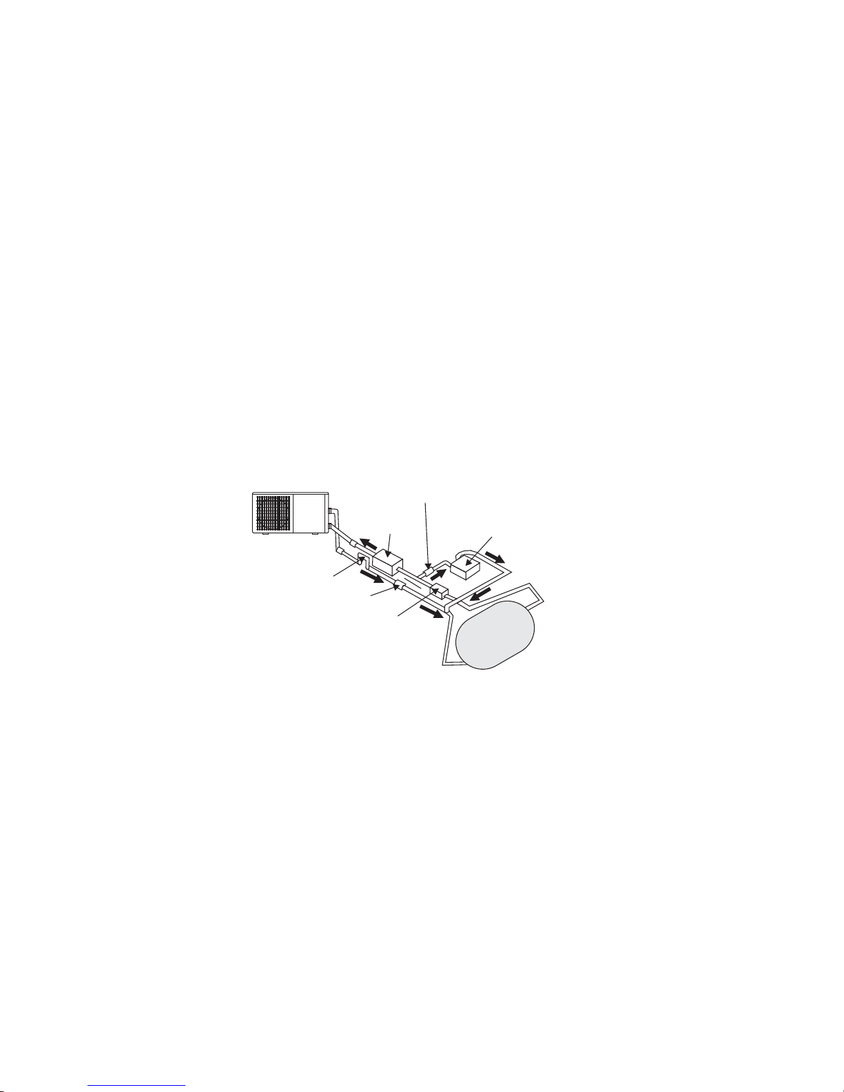
1.7 Pool system set up
1.8 Connecting the by-pass
Valve 1
Valve 2
Valve 3
BY-PASS
F
r
o
m
f
i
l
t
e
r
T
o
p
o
o
l
OUT IN
HEATPUMP
Powe r cable i nlet
Heat Pump
Outlet
Inlet
Condensed water draining pipe
Draining nozzle
Discharge water to pool
Pool w ater inl et
Water pu mp
Filter
Water p roces sor
Side connection valve
6
Figure 1-5
Figure 1-6
Adjust the by-pass as follows:
open the 3 valves completely
slightly close valve 1 until water
pressure has increased with approximately 100 to 200 grams,
close valve 3 about halfway to
adjust the pressure of the refrigerant gas in the un it
Page 11
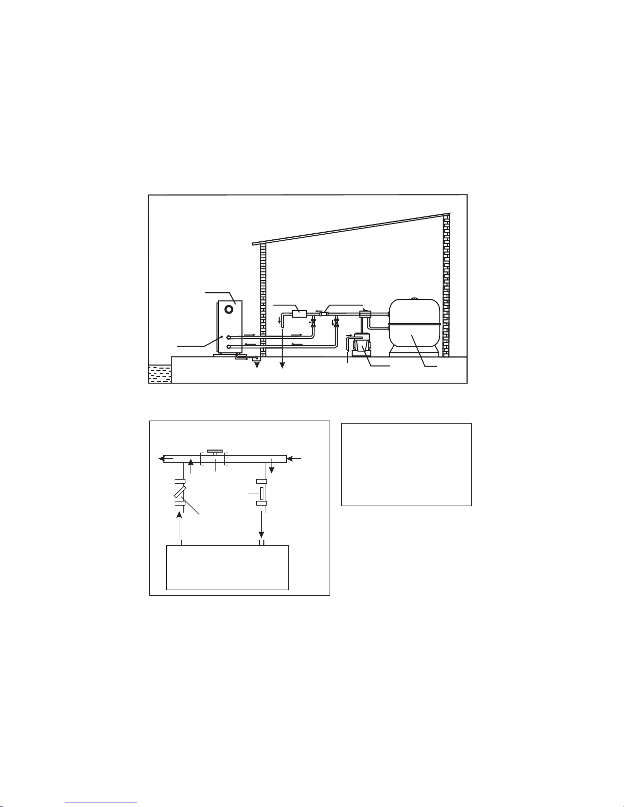
Although the heat pump is electrically isolated from the rest of the unit, this only preventsImportant—
the passage of electricity to or from the pool water. Grounding the unit is still required to protect
yourself from short circuits inside the unit. Make for adequate ground connection.
Check ifthe electrical mains voltage corresponds with the operating voltageof the heat pump prior to
hoo king up t he unit .
It is recommended to use a separate fuse(slow type-D-curve)as well as adequate wiring(see table below).
For h ori zontal models : remo ve th e panel o n the rig ht of the fa n openi ng.
For vert ica l model s: remove th e cur ve pane l in the front s ide.
Connect the electrical wires with the terminal block labelled Power Supply .“”
Next to this connection, thereis a second terminal block labelled Water Pump ,to which the filter“”
pump (max.5A/240V)can be connected. This is connectionmakes it possible to control filter pump
operation with the heat pump. See further at Parameter setting table (Parameter 9) for the different
possibilities.
Remarks
—for mo dels wi th 3 phas es, swi tch ing 2 pha ses may caus e in inve rsio n in the rotational direction
of electrical motors, which could damage the unit. Therefore,a protection device has been built in, which
wil l interrup t the circuit if th e conne ction has no t been performe d correctly.
1.9 Electrical hook-up
7
Figure 1-7
Figure 1-8
2x2.5+2.5
2x2.5+2.5
2x2.5+2.5
2x4.0+4.0
2x4.0+4.0
4x2.5+2.5
4x2.5+2.5
Mida.Black 8
Mida. Black10
Mida. Black 12
Mida. Black 14
Mida. Black 17
Mida. Black 21
Mida. Black 26
220-240
220-240
220-240
220-240
220-240
380-400
380-400
16
16
20
25
32
16
20
6.57
7.85
10.72
11.57
13.3
6.5
8.0
Cable diameter(mm )
2
(for a max.length of 10 meters)
Model
Voltage( )V
Fuse(A)
Nominal
Current(A)
Page 12

1.11 Condensation
1.10 First time start-up
Time delay— the unit is equipped with a built-in3-minute start delayincluded to protectelectrical
components and contacts. After this time delay, the unit will automatically be restarted. Even a
brief interruption of the power supply willactivate the startdelay and preventthe unit from starting
immediately. Additional interruptions of the power supply during the delay period will have no effect
on the 3-minute countdown.
Water flo w switch— the uni t is equi pped with a fl ow switch th at is switch ed on when eno ugh wate r has
flowed through the unit and that isswitched off when the waterflow becomes too low. (E.g. When the
filter pump is switched off).
Whe n the swi mming pool w ater is be ing hea ted b y the heat pum p, the incoming a ir is coo led down qui te
a bit , which c an ca use con densatio n on the fins of t he evaporat or. Con densed vol umes can atta in several
litres per hourunder highatmospheric humidity.Sometimes, this is wrongfullyinterpretedas a waterleak.
Dep endin g on the start ing temperature of the po ol wa ter a nd the ai r temperature, it can take s everal days
for the water to reach th e desired tempe rature. Coveri ng the pool ca n dra sti cal ly redu ced this per iod.
When all connections have been made and checked, you should follow these steps:
1. Turn on th e filte r pump. Chec k for l eaks and verify f low to and from the p ool.
2. Turn on the electrical power supply to the unit, then press the ON/ OFF key on the electronic control
pan el. The u nit sho uld start wh en the time de lay period h as lapsed .
3. When the unit has been running for a couple of minutes, check if the air leaving the unit is cooler.
4. Check the performance of the flow switch as follows: with the unit running, turn the filter pump off.
The unit should also switch off automatically. If not, the flow switch must be readjusted.
5. Al l the uni t and fil ter pum p to ru n 24 hours a day until the d esired pool water tempe rature is reache d.
When theset temperature is reached,the unitswitches itself off.The unitwill now automatically restart
(as long as your filter pump is running) when the temperature of the pool water experiences a drop of
more than 1 below the set temperature.℃
Note- Inorder for the unitto heat the pool(or spa),the filterpump must be running sothat thewater can
circulate through the heat pump. Without this circulation, the heat pump will not start.
8
Page 13
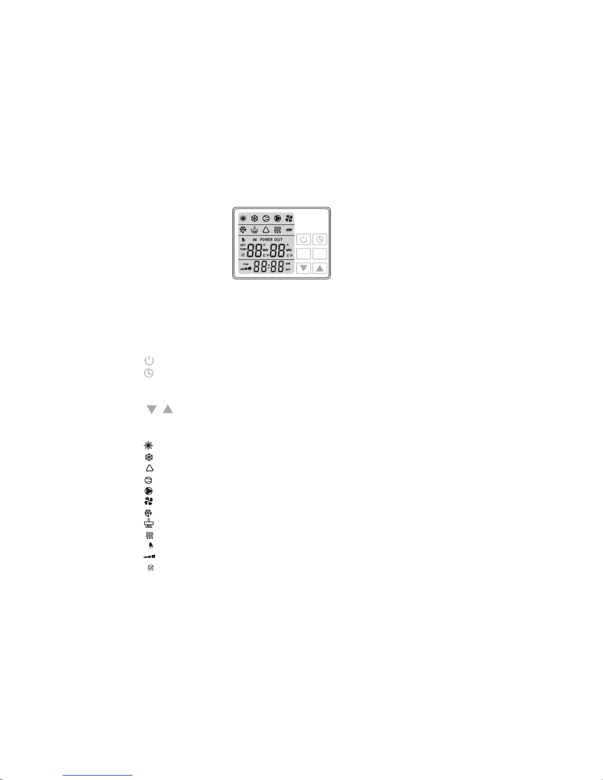
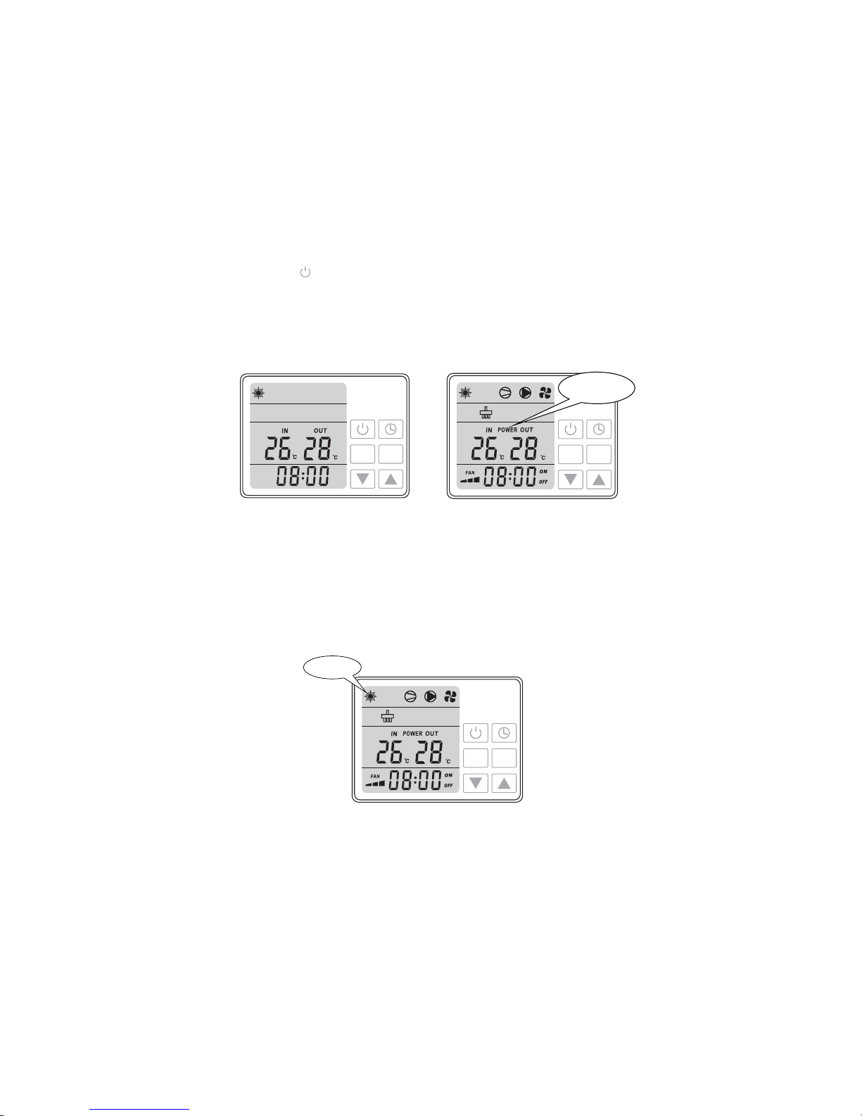
2.Control of the heat pump (New color LED )
MODE
MENU
2.1 Controller illustration:
When heat pump is supplied with power, controller will display with full screen, shows that it is already
connected. If connection fails in 10 seconds, please check connections between communication cable
and control display, or replace with another control display.
Button functions:
button: ON/OFF switch to start or stop heat pump.
MODE button: To swi tch b etween heatin g, cooling a nd auto m ode.
but ton :Timer button to set t imer on and ti mer off.
MENU button: To enter pa ram ete r settin gs and co nfirm setting s.
button: To increase or decrease value.
Icons definitions:
--h eatin g ico n, show ing heat pum p is in heatin g mod e.
--c ooling ico n, showing h eat p ump is in c ooling mod e.
--a uto icon, sh owing h eat p ump is in a uto mod e.
--compressor icon, showing compressor status.
--w ater pum p icon, s howing water pump status.
--fan ic on, showin g fan status.
--d efrost icon, sh owi ng defrost status.
--four way valve icon, sho wing four way valve status .
--electric heatericon, showing electricheater status(onlywhen external electric heater isconnected)
--alarm icon, showing system alarm.
--fan sp eed ico n, showing h igh (3), med ium(2) and l ow(1) fan sp eed.
--key pad loc k ico n, show ing button s on the control displ ay are locked .
Note: 1. Heat pump is not equipped with electric heater internally, only provides terminal for external
connection.
2. Fan speed is automatically controlled by ambient temperature, not manually.
Figure 2-1
9
Page 14
2.2 Power ON/OFF he at pump
Press button to switch on heat pump.
Figure 2-2
Once the heat pump is powered on all related running component icons will be lightened as well as
POWER displayed in the middle of display to show system is in running status.
Figure 2-2 shows heat pump in standby status and figure 2-3 shows heat pump in running status.
The l eft temperature sh ows f low wate r tem peratu re while the r ight tempe rature is the r etu rn water
temperature.
Figure 2-3
MODE
MENU
Press MODE button to select auto, heating or cooling mode, related indicator icon will be lightened as a
symbol t o show heat pump is i n eithe r auto , he ati ng or coolin g mode.
2.3 How to change mode
Figure 2-4
10
MODE
MENU
running status
MODE
MENU
heating mode
Page 15
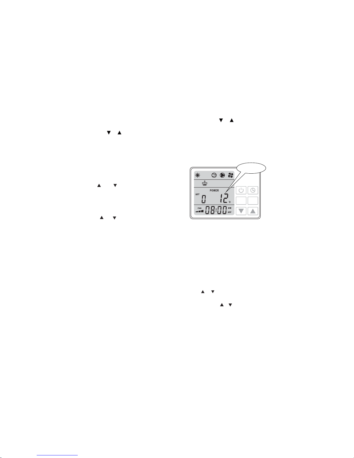
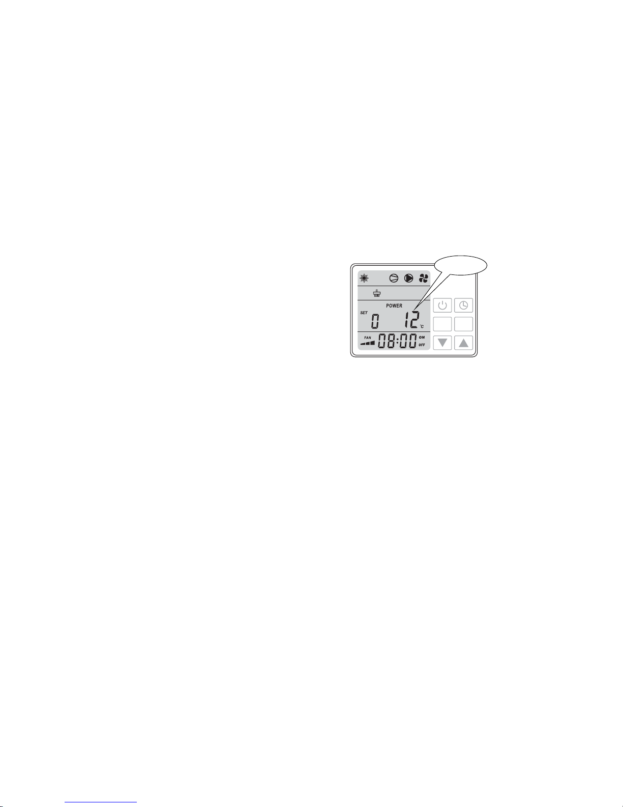
2.5 Check and set parameters
Press button for 5 seconds display willMENU
sho w parameter num ber with value fl ashin g
together.
Mov e and b utton to che ck re quired
parameter settings.
Select desired parameter and press Menu button
for resetting pa ram ete r. Param eter numbe r stays
fixed wh ile para meter valu e rem ains flash ing.
Move and button to adjust the value.
Press Me nu button to conf irm the setting .
Without any further movement on the display button
in 5 seconds it will return to main interface automatically.
Note: All parameters can be changed ONLY under standby status !
2.4 Adjust desire d water temperature
1.First select desired mode, auto, heating or cooling.
2.No matter the heat pump is under standby status or running status, press or , display will
show the desired water temp. of selected mode with a flashing value, then change the water temp.
by mo ving or as reques ted .
11
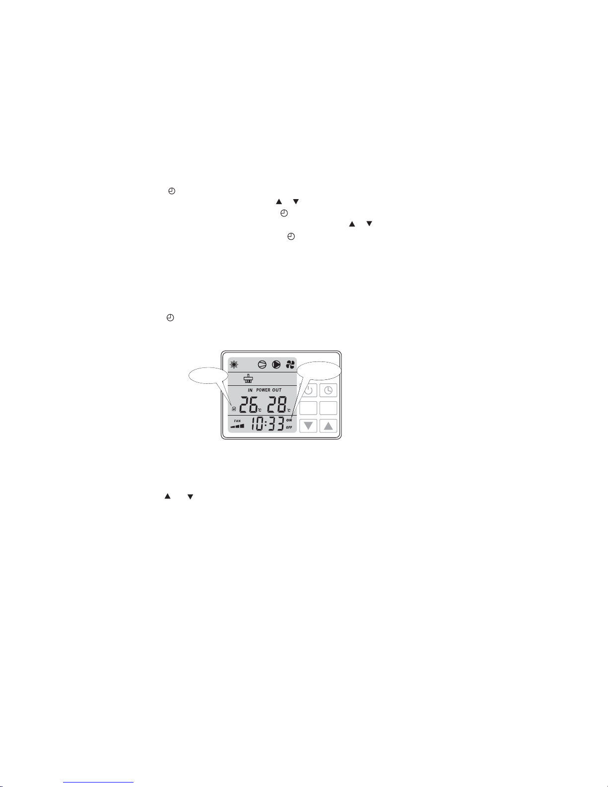
Press ME NU button in a q uick stop to acti vate time setting.
Whe n hour nu mbers are fl ash ing it is avai lab le for revision m ove o r to fix ho ur numbers.
Press ME NU button to conf irm hour settin g.
Min ute num bers start fl ashin g once th e hour nu mbers are confirme d, move or to fix minute nu mbers.
Press ME NU button to conf irm minute setting .
2.6. Setting Time
MODE
MENU
parameter
value
Figure 2-5
Page 16

Parameter
Definition
Range
Default Remark
Type o f unit:
0=Cooling only
1=Heating &cooling
2=Heating & cooling + Auxiliary heating
3=Heating only
837~ ℃
~840℃
~10 90Min
-30 0~ ℃
~230℃
~112Min
14~
01~
03~
01~
28℃
28℃
45Min
-7℃
13℃
8Min
1
1Yes()
1
0
Adjusted
by Technicians
Adjusted
by Technicians
Adjusted
by Technicians
Adjusted
by Technicians
Adjusted
by Technicians
Adjusted
by Technicians
Adjusted
by Technicians
Adjusted
by Technicians
Des ired wat er temp eratur e in auto mo de
Act ual inl et water t emp.
Actual outlet water temp.
Coi l temp. i n system 1
Ambient temp.
840~ ℃ 30℃
Adjusted
by Technicians
-9 99~ ℃
-9 99~ ℃
-9 99~ ℃
Measured Value
Coi l temp. i n system 2
-9 99~ ℃
Measured Value
2.7 Parameter table overview
12
0
1
2
3
4
5
6
7
Desired water temperaturein cooling mode
Desired water temperaturein heating mode
Defrosting cycle
Evaporatortemperature setpoint for starting defrosting
Evaporatortemperature setpoint for stopping defrosting
Maximum duration for defrosting
Quantity ofsystem
Restart after powerfailure
Adjusted
by Technicians
Adjusted
by Technicians
Water temperaturedifference setting for restarting
Low pressure switch detection:
0 = Low pressure switch will detect after compressor
has been running for 10 min
1=Low pressure switch will detect after compressor
has been running for 60 min
2=Low pressure switch will never detect
0
-9 99~ ℃
120℃~ 2℃
Measured Value
Measured Value
Measured Value
Adjusted
by Technicians
Adjusted
by Technicians
Dif ferent wo rking m ode of wa ter pum p:
0= wat er pump i s always o n
1 = water pump is only running when the heat
pump is switched on
0/1/2
9
10
11
12
A
b
C
d
E
8
Page 17
2.7 Setting Timer on/ Timer off
2.8 Cancelling Timer on and Timer off
Press bu tton to acti vate, time an d ON /OFF s tar ts flashin g together.
Press but ton to can cel the time r and ON/ O FF icon s wil l disap pear on t he disp lay.MENU
Press and button together for 5 seconds, display will show lock icon. Do this again to unlock.
Press bu tton to enter timer se tti ng.
Hou r data will be f lashing wi th ON, mo ve or t o set i t.
Con firm timer o n hour se tti ng by pressing bu tton.
Min ute data starts flas hing once ho ur setting i s confirme d, move or to set it.
Con firm timer o n minut e settin g by pressin g button.
Onc e Timer o n is set an d con firme d Timer off wi ll be activated.
Follow t he same s tep s as setti ng Time r on to set T ime r off.
2.9 Key pad lock
13
MODE
MENU
Key pad locked
Figure 2-6
Timer ON/OFF
Page 18

3. Protection systems
3.1 Water flo w switch
Equipped with flow switch the heat pumpwill not work when the filter pumpis not working (and the
water is not ci rculatin g).
Thi s system p revent s the heat pum p fro m heating only th e water present in the h eat pum p its elf.
The p rotectio n also sto ps the he at pump i f water ci rcu lat ion is cu t off or stopp ed.
3.3 Overheating protection on the compressor
Thi s protecti on prote cts the c ompressor from overhe ating .
3.2 Refrigerant gas high and low pressure protection
The h igh pre ssu re protection m akes sure the heat pum p is not damag ed in case of over press urisatio n of
the gas. The lowpressure protection emitsa signal when refrigerant isescaping fromthe conduits and the
unit can not be kept running.
3.4 Automatic defrost control
Whe n the air i s very hu mid and cold , ice can fo rm on the evaporator. In that event, a thin layer of ice a pp-
ears that will grow increasingly bigger as long as the heat pump is running. When the temperature of the
evaporator has b eco me too lo w, auto matic d efrost cont rol w ill b e activated, wh ich wil l revers e the heat
pum p cycle s o that hot refrigerant gas i s sent th rou gh the evaporato r durin g a brief p eriod of tim e to
def rost it.
3.5 Temperature difference between inflowing and outflowing water
Dur ing nor mal ope ration of th e hea t pump, the te mperat ure d ifference b etween inf lowing and o utflowin g
water will approximate 1to 2 In the event that the pressure switch does notwork and that the water℃.
stops circulating, the temperature probe monitoring the outflowing water will always detect a rise in
temperature.As soonas the temperature difference between inflowingand outflowing waterexceeds 13℃,
.the heat pump will be automatically turned off
3.6 Low temperature cut-out
If, dur ing coolin g, the tempe rature of the o utflo wing water reaches 5 or drops below th is temp erature,℃
the heat pump will turn itself off until the water temperature reaches or exceeds 7 again.℃
3.7 Anti-frost protection during winter
Thi s protecti on ca n only be a ctivated if the h eat pum p is in S TAND-BY stat us.
14
3.8 First anti-frost protection
If the filter pump is controlled by the heat pump (regardless of the value for parameter 9) and when the
water temperature lies between2 and 4 and the airtemperatureis lower than 0 the filter pumpwill℃, ℃,
be automatically turnedon to prevent the water from freezing in the piping.This protectionis deactivated
whe n the tem peratu re ri ses again.
3.9 Second anti-frost protection
If thewater temperaturedrops even more, that is, below2 (during long frost periods), the heat pump℃
will also start running to heat the water until its temperature approximates 3 When this temperature℃.
is reach ed, the h eat pum p will stop, but ant i frost protec tio n wil l rem ain act ive u ntil condi tions c hange .-
Page 19

4. Direction
4.1 Swimming pool water chemistry
pH
Free chlorine(mg/1)
TAC(mg/1)
Salt(g/1)
Important: failure to comply with these limits will invalidate the warranty.
Not e: exceedin g one or se veral li mits can damage the heat pump beyond repair. Always install water
treatment equipment past the heat pump s water outlet,especially ifthe chemicalsare automatically'
added to the water.
A check valve should also be installed between the outlet of the heat pump and this equipment inord er to p revent p rod ucts from flowi ng back into the he at pu mp if the filter pump s top s.
Spe cial attentio n should be pa id to t he chem ical ba lance of the p ool water. The pool water values s hould
always stay within the following limits:
Min
7.0
0.5
80
Max
7.4
1.2
120
3
4.2 Heat pump winterizing
Important: failu re to take the neces sary precauti ons for winteri zing can dam age t he heat pump ,
which will invalidate the warranty.
The heat pump, filter pump, filter and conduits must be protected in areas where the temperature can drop
bel ow the freez ing point, Evacuate all water from the heat pump a s follows:
1. Interrupt the electrical power supply to the heat pump
2. Close the water supply to the heat pump: completely close valves 2 and 3 of the by-pass
3. Di sconn ect the water inlet an d outlet couple r fittings o f the hea t pump and let t he wa ter d rai n out of the
unit.
4. Lo osely reattach water inlet a nd outlet co upler fitting s to th e heat pu mp in order to prevent dirt
from setting into the conduits.
Note: these precautions should not be taken if you choose to use the built-in anti-frost protection.
4.3 Restarting the pump after winter
If you purgedyour heat pumpfor winterizing, you shouldundertakethe following steps torestart it inspring:
1. Check first if there is no dirt in the conduits and if there are no structural problems
2. Ch eck if th e water inlet and o utlet coup ler f ittin gs are adequately fastened to the h eat p ump
3. St art t he filt er pump to start the water flow to t he he at pump . Set the by-p ass agai n.
4. Reconnect the electrical power supply to the heat pump and turn it ON.
15
Page 20

Condensation canoccur whenthe heatpumpis running. Thiscondensationcan flow away throughan opening
in the base pan of the unit. The amount of condensation water will increase when atmospherichumidityis
high. Remove any dirt that could possibly hamper the evacuation of condensation.
10 to 20 litres of condensation water can be produced while the unit is running. If more condensation is
produced, stop the heat pump and wait for one hour before checking for leaks in the conduits.
a quickway toverify that the water running through the condensation drain is indeedNote:
.condensation, is to shut off the unit and keep the pool pump running Ifthe water stops running out
of thecondensation drain, it is condensation. AN EVEN QUICKER WAY is to TEST THE DRAIN
WATER FOR CHLORINE. If no chlorine is detected, the drain water is a result of condensation.
Also take care toleave air inletand exhaustpassages free. Prevent exhaust airfrom immediately re-entering
the unit through the inlet.
4.4 Check-up
Our heat pumps have been developed and built to last, that is, if they have been installed correctly and can
run undernormal conditions. Regular check-ups areimportant if you want your heat pump tofunction
safely and effic ientl y for years on end.
1. Ma ke for easy acc ess t o the ser vice panel .
2. Keep the area surrounding the heat pump free of contingent organic waste.
3. Prune the vegetation near the heat pump so that there is enough free space around the pump.
4. Removecontingent water sprinklersfrom thevicinity ofthe heat pump. They can damagethe heat pump.
5. Prevent rain from directly running off a roof onto the heat pump. Install proper drainage.
6. Do not use the heat pump if it has been flooded. Immediately contact a qualified technician to inspect
the heat pump and repair it if should prove necessary.
16
Page 21

5. Maintenance and inspection
5.1 Maintenance
Che ck the water inle t and drainage of ten . The wate r and air infl ow into the system s hould be suf fic ient√
so that its performance and reliability doesnot get compromised. You should clean the pool filter
regula rly to avoid dama ge to the unit c aused by clo gging o f the filter.
The area around the unit should be spacious andwell ventilated. Clean the sides of the heat pump√
regula rly to ma int ain g ood hea t exchange an d to save en erg y.
Che ck if all p rocesses i n the uni t are operation al and pay specia l attention t o the operation perssure of√
the refrigerant system.
Check the power supply and cable connections regularly. Should the unit begin to function abnormally√
or should you notice a smell from an electrical component, arrange fro timely repair or replacement.
Youshould alsopurge the waterif the unit will not work for an extended periodof time. You should√
check allparts of the unit thoroughly and completely fill the system withwater before turning it on
again afterwards.
Improper installation mayresult in an electrical dischargethat could lead to deathof-or serious injury
to-pool users, installers or others due to electrical shock and may also cause damage to property.
attempt to modif y the int ern al conf igurat ion of the hea t pump.DO NOT
1. Keep your hands and hair clear of the fan blades to avoid injury.
2. If you are not familiar with your pool filtering systems and heat pump:
a. attempt to adjustor service without consulting your dealer oryour professional poolor airDo not
conditioning contractor.
b.Read the entire installation and user manual before attempting to use, service or adjust the unit.
C.Start the heatpump at least 24hours after itsinstallation in order to preventdamage to the compressor.
5.2 Trouble shooting guide
Note: Switch off thepower priorto maintenance orrepairs.
IMPORTANT REMARK: if amalfunction can not be resolved immediately, in order to analyse the
,
problem itself we will need to know the message(error code) that isdisplayed on thecontroller, as
well as the values for the settings(parameter 00-10 for LCD display while parameter 0-Afor LED
display) andforstatus of the heat pump (ambient temperature water inlet outlet temperature
,/
and system coil temperature) justbefore the failure or, if thisis impossible, just after it.
Please keep this information at hand when calling customer service.
On the following pages, you willfind anoverview ofthe different types offailure problems thatcan occur,
along with directions to solve them.
17
Page 22

Problem:
Observation:
Possible cause
Solution
the h eat pum p works no rmall y but the re is no or i nsuff icien t heatin g
The s creen d isplay s the tem peratu re but no e rror cod es
1. In s uffic ient cap acity o f the hea t pump in p ropor tion to t he
size o f the swi mming p ool
2. Th e compre ssor wo rks but t he fan do esn't
3. Th e fan work s but the c ompre ssor do esn't
4. Th e heat pu mp has no t been pl aced on a n optim al locat ion
5. Fau lty tem peratu re sett ing
6. By -pass n ot adju sted
7. Ma ssive i ce forma tion on t he evap orator
8. Not enough refrigerant
1. In stall a la rger si zed mode l or an ext ra heat pu mp.
Cov er the po ol to limi t heat lo ss
2. Ch eck the e lectr ical wi ring of t he fan. Re place t he
con dense r or the fan m otor if n ecess ary.
3. Ch eck the e lectr ical wi ring of t he compr essor.
Replace thecondenser or the compressor ifnecessary.
4. Ma ke for suf ficie nt air cir culat ion(s ee manu al for
details)
5. Se t the cor rect tem peratu re
6. Have the by-pass readjusted by the installer
7. Ha ve the set tings fo r autom atic de frost co ntrol
checked by the installer
8. Ha ve the hea t pump ch ecked by a r efrig eratio n
technician
Problem:
the h eat pum p doesn 't work
Observation:
the s creen d oes not l ight up an d the fan /compr essor d oesn' t make a sou nd
Possible cause
No electrical power supply
Solution
Check power supply (wiring, fuses, )…………
Problem:
the h eat pum p doesn 't stop
Observation:
the s creen d isplay s the tem peratu re but no e rror cod es
Possible cause
Solution
1.Wrong setting of parameters
2. Pr essure s witch o ut of ord er
3. Electrical failure
1.Check the setparameters and adjust themif necessary
(settings justabove the capacityof the heatpump)
2. Ch eck ope ration o f the pre ssure s witch by t urnin g
off t he filte r pump an d resta rting i t. If the h eat pump
doe sn't re act to thi s, the pr essur e switch m ust be
adjusted or replaced.
3. Contact your installer
The h eat pum p works no rmall y but the w ater is co oling d own ins tead of h eatin g up
The s creen d isplay s the tem peratu re but no e rror cod es
Problem:
Observation:
Possible cause
Solution
1.The wrong mode has been selected
2. The controller is out of order
3. Th e 4-way va lve is ou t of order
1.Verify the parameters, select the correct mode
2. Ch eck the v oltage i n the ele ctric al wiri ng to the
4-way valve. If no electric potential is measured,
replace the controller
3. Ch eck the v oltage i n the ele ctric al wiri ng to the
4-way valve. If electric potential is measured,
rep lace th e coil. If t he prob lem per sists, h ave the
hea t pump ch ecked by a r efrige ratio n techni cian
18
Page 23

Problem:
Observation:
Possible cause
Solution
abnormal amount of ice formed on the evaporator
the e vapora tor is for t he most p art cove red in ic e
1.Insufficient air inflow
2.High water temperature
3.In correc t setti ng of aut omati c defros t contro l
4.Th e 4-way va lve is ou t of order
5.Not enough refrigerant
1.Ch eck the l ocati on of the h eat pump a nd remo ve any
dir t that co uld be pre sent on t he evap orator
2.If t he pool w ater is al ready q uite ho t (warme r than
29?),the probability of ice formation increases.
Low ering t he set tem perat ure is a pos sible o ption
3.Ch eck the s etting o f the def rosti ng func tion tog ether
with your installer.
4.Ch eck the v oltage i n the ele ctric al wiri ng to the 4
-way valve. If electric potential is measured, replace
the c oil. If t he probl em pers ists, h ave the he at pump
checked by a refrigeration technician.
5.Ha ve the hea t pump ch ecked by a r efrig eratio n
technician.
Problem:
Observation:
Possible cause
Solution
water leak
the re's an a mount of w ater un der the h eat pum p
1.Condensation due to atmospheric humidity
2.Water leak
1.No action required
2.Try to l ocali ze the le ak and ch eck for th e prese nce
of ch lorin e in the wat er. If that i s the cas e, the he at
pump must be temporarily replaced during repair.
19
Page 24

5.3 Failure code table for plug-in type PCB
20
Protection/Failure
Wire
controller
E3/EE3
No display
Check Solution
P1/PP1
1. Ch eck the conne ction o f inlet w ater
sensor.
.2. C heckif thesensor isbroken
1. Reconnect the sensor.
2. Rep lace th e senso r.
P2/PP2
1. Checkthe connection ofoutlet water
sensor.
.2. Check ifthe sensor isbroken
1. Reconnect thesensor.
2. Replace thesensor.
P3/PP3
1. Ch eck the co nnect ion of co il 1
temperature sensor.
.2. Check ifthe sensoris broken
1. Reconnect thesensor.
2. Replace thesensor.
P10/PP10
1. Ch eck the co nnect ion of co il 2
temperature sensor
2. Check ifthe sensoris broken.
1. Reconnect thesensor.
2. Replace thesensor.
P5/PP5
1. Ch eck the co nnect ion of am bient
temperature sensor.
.2. Check ifthe sensoris broken
1. Reconnectthe sensor.
2. Replace thesensor.
E12/EE12
1. Checkif wiring connectionof flow switch
is incorrect position.
2. Checkif enough waterflow.
3. Checkif flow switchis broken.
4. Check ifwater pump is working.
1. Reconnect the wiring.
2. Increase enough water flow.
3. Replace flow switch.
4. Repair or replace water pump.
E4/EE4
1. Che ck if high pressure switch is broken.
'2. Checkifthere sjaminwatercircuitor
waterflow n otenough.
3. Ch eckif refrigerantcircuit ja m.
E14/EE14
1. Check if thereis enough water flow volume.
2. Chec k if inle t/o utl et water temp sensor is working..
1. In crease w ater fl ow.
2. Rep lace re lated se nsor.
E8/EE8
Che ck the con necti on
Reconnect the connection wire.
P7/PP7
No action required
Water flow switch failure
Defrosting
Inl et water t emp. se nsor fai lure
Out let wate r temp. s ensor fa ilure
Coi l 1 temp. se nsor fa ilure
Coi l 2 temp. se nsor fa ilure
Ambient temp. sensor failure
Anti-freeze protection for cooling
High pressure protection Ⅰ
Failure of excessive temp. difference
bet ween wat er inlet & o utlet
Communication failure
Winter anti-freeze protection Ⅰ
Winter anti-freeze protection Ⅱ
P7/PP7
No action required
Orde r of phas es inco rrect
Reconnect thephases inright order
Orde r of phas es inco rrect
(on ly for 3 pha se mode l)
E1/EE1
1. Ch eck if hig h or low pressure switch is broken.
2.Checkiflackofrefrigerant.
3. Ambienttemp. and waterinlet temp.is
too low.
E6/EE6
Low pressure protection Ⅱ
High pressure protection Ⅱ
E5/EE5
1. Replace high pressure switch.
2. Remove cause of blockage or
increase water flow.
3. Send heat pump to dealer for
detailed check.
Low pressure protection Ⅰ
E2/EE2
1. Replace l ow pressure swit ch.
2. Fill up with enough refrigerant.
3. Remove cau se of blockage or
decreas e water flow.
4. Send he at pump to dealer for
detailed check.
1. Check ifthere isany jam inthe watercircuit.
2. Checkif the waterflow volumeis enough.
3. Check ifthe waterpump isworking.
E14/EE14
1. Rem ove the j am.
2. Increase thewater flowvolume.
3. Repair orreplace thew aterp ump.
Protection for excessive temp. difference
between water inlet & outlet
Page 25

6.Name plate & wiring diagram
6.1Name plate
21
Page 26
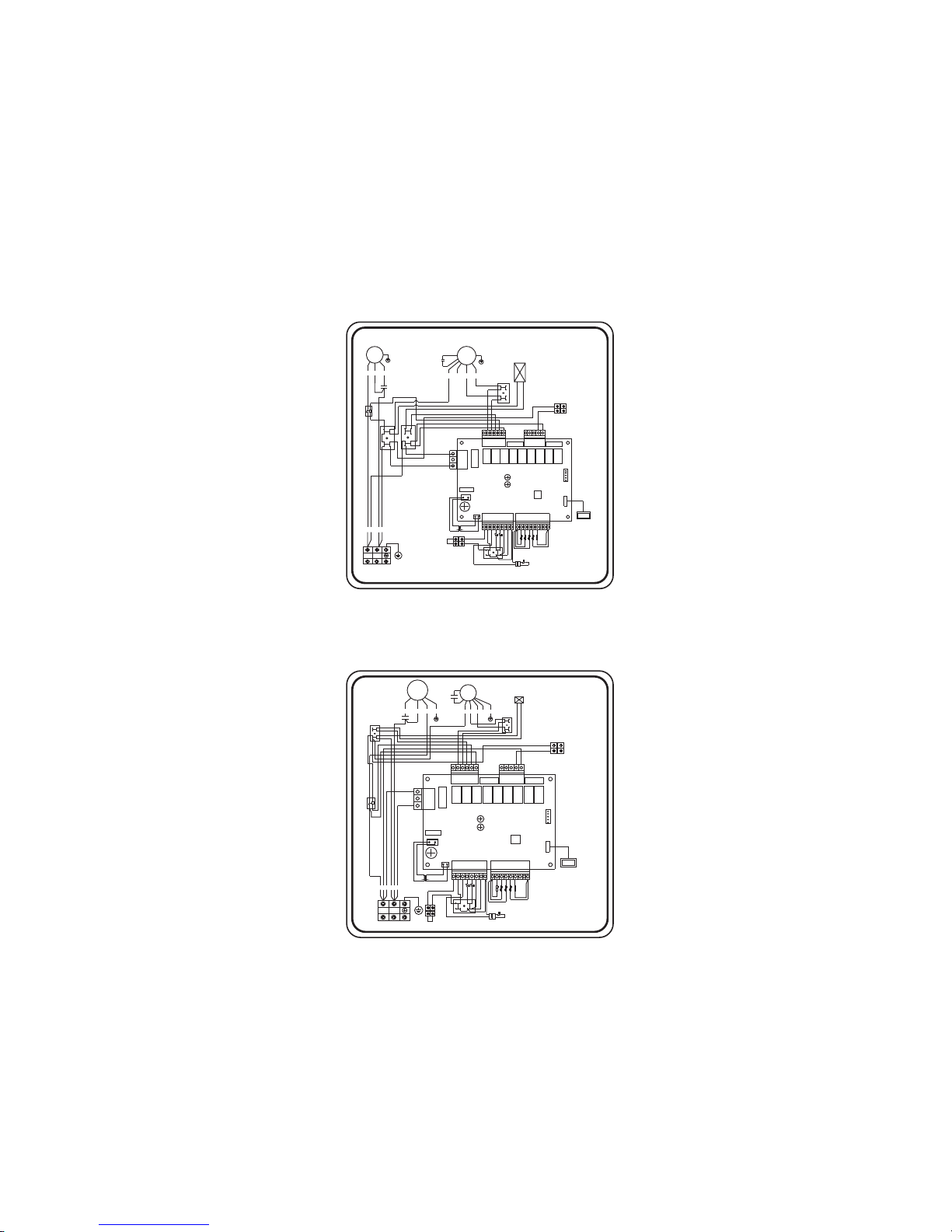
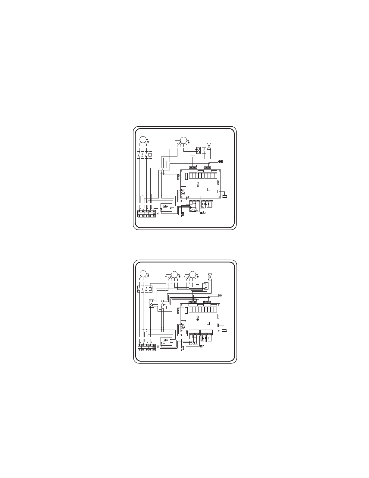
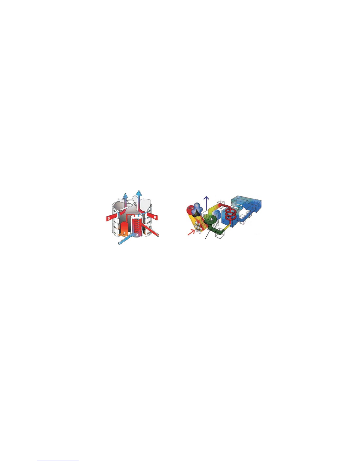
6.2 Wiring diagram
22
BLU
RED
BLURED
L
N
RED
ORG
WHI
YEL
BLU
BLK
C
4-way valve
FM
CM
KA9 5A/KA8 5A/KA75A/KA6 5A/KA55A/KA4 5A/KA3 5A/KA2 5A/KA1 5A/
IC
AC L- AC L-
AC N-
AC L-
220V AC/
12V AC/
Transformer
Wire controller
PP
N5
GND
FUSE
FUSE
FUSE
L
N2
Y01
KM
L
L
32 3028 29
LN
POWER SUPPLY
BLK
A1
A2
C
R
S
C
T1:
T2:
T3:
T4:
Ambient temp
Coil temp
Outlet water temp
Low Pressure switch
High Pressure switch
K1:
K2:
Inlet water temp
CM:Compressor
FM:Fan
KM:AC contactor
I15A<.
water pump
N6
B01
NOTE:
For cur rent of w ater pu mp
above 1.5Amp.
please externally equip
suitableA/C contactor.
External control
terminal
Water flow switch
LN
PE
PE
1103-1708
CC395-V1.0
GND
GND
GND
T2T1 T3 T4
K1K2
R=5K
KA9 5A/KA85A/KA7 5A/KA6 5A/KA5 5A/KA4 5A/KA3 5A/KA2 5A/KA1 5A/
AC L- AC L-
AC N-
AC L-
LN
RED
BLU
POWER SUPPLY
220V AC/
12V AC/
Transformer
YG/
YG/
REDBLU
BLK
ORG
BLU
C
C
C
R
S
BLKWHI
RED
N2
4-way valve
FM
CM
Wire controller
KM
A1
A2
N
N1
L
N5
Y01
FUSE
FUSE
FUSE
L
L
L
T1:
T2:
T3:
T4:
Ambient temp
Coil temp
Outlet water temp
Low Pressure switch
High Pressure switch
K1:
K2:
Inlet water temp
CM:Compressor
FM:Fan
KM:AC contactor
32 3028 29
PP
GND
YEL
A
I15A<.
water pump
N6
B01
NOTE:
For current of water pump
above 1.5Amp.
please externally equip
suitableA/C contactor.
External control
terminal
Water flow switch
N
PE
1108-1726
CC395-V1.0
IC
GND
GND
GND
T2T1 T3 T4
R=5K
K2 K1
Mida.Black 8 / 10 / 12
Mida.Black 14 / 17
Page 27
CC159 V1 0-.
CP4
CP3
T
S
R
BLURED BLKWHI
AB NC
WHIBLKRED
642
531
TSR
A2
A1
W
V
U
N1
L
RED
ORG
WHI
YEL BLU
BLK
C
POWER SUPPLY
4-way valve
FM
CM
KA95A/KA85A/KA75A/KA65A/KA55A/KA4 5A/KA3 5A/KA2 5A/KA1 5A/
IC
AC L- AC L-
AC N-
AC L-
220VAC/
12V AC/
Transformer
T1:
T2:
T3:
T4:
Ambient temp
Coil temp
Outlet water temp
Wire controller
PP
Low Pressure switch
High Pressure switch
K1:
K2:
N5
GND
FUSE
FUSE
FUSE
L
N
L
N2
Y01
KM
LL
32 3028 29
Inlet water temp
CM:Compressor
FM:Fan
KM:AC contactor
AB
I15A<.
water pump
N6
B01
NOTE:
For current of water pump
above 1.5Amp.
please externally equip
suitableA/C contactor.
External control
terminal
TSRN
PE
Water flowswitch
1110-1756
CC395-V1.0
T2T1 T3 T4 R 5K=
GND
GND
GND
K2 K1
Mida.Black 21
CC159 V1 0-.
CP4
CP3
T
S
R
BLURED
BLK
WHI
AB NC
WHIBLKRED
642
531
TSR
A2
A1
W
V
U
N1
L
N
RED
ORG
WHI
YEL
BLU
BLK
C
POWER SUPPLY
4-way valve
FM
CM
KA95A/KA8 5A/KA7 5A/KA6 5A/KA5 5A/KA45A/KA35A/KA2 5A/KA1 5A/
IC
AC L- ACL-
AC N-
AC L-
220VAC/
12V AC/
Transformer
T1:
T2:
T3:
T4:
Ambient temp
Coil temp
Outlet water temp
Wire controller
PP
Low Pressure switch
High Pressure switch
K1:
K2:
N5
GND
FUSE
FUSE
FUSE
L
N2
Y01
KM
32 3028 29
Inlet water temp
RED
ORG
WHI YEL BLU
BLK
C
FM
CM:Compressor
FM:Fan
KM:AC con tacto r
1# 2#
A
I15A<.
water pump
N6
B01
NOTE:
For current of water pump
above 1.5Amp.
please externally equip
suitableA/C contactor.
Water flowswitch
External control
terminal
TSRN
PE
1111-1721
CC395-V1.0
GND
GND
GND
T2K1T3T4
R=5K
K
2
Mida.Black 26
23
Page 28

ACHTUNG: Dieses Hanbuch beinhaltet alle infomrationen die für die Benutzung und die Installation ihrer
Wärmepumpe erforderlich sind.
Der Installateur mussdas Handbuch gründlichdurchlesen durchlesen und den Anweisungenstrikt folgen,
sowo hl bei der I mpl ement ierung als a uch bei d er Wartung.
Der Installateur ist verantwotlich für die Installation des Produkts und sollte allen Anweisungen des Herst-
ellers sowie allen Vorschriftenin denAnwendungen folgen.Inkorrekte Installationgegen dieAnweisungen des
Handbuchs macht dieGarantie nichtig.
Der Hersteller lehnt jede Verantwortung ab für Schäden die durch Menschen, Objekte oder Fehler
die auf Nichtbefolgung von Anweisungen im Hanbuch beruhen. Jede Nutzung die bei Herstellung nicht
vorgesehen war wird als gefährlich eingestuft.
WARNUNG: Bitte le eren Sie das Wa sser in d er Wärmepumpe i m Win ter o der w enn d ie Temperatur unter 0° C
sin kt, son st wird der Titanium -Wechsler d urch Frost besch ädi gt. In diese m Fall ist d ie Garantie nic hti g.
Bitte schalten Siesimmer die Stromversorgung aus, wennsie die Kabine ffnen wollen umins InnereWARNUNG: ö
der Wärmepumpe vorzudringen, da drinnen Hochspannung herrscht.
WARNUNG:Bittebewahren Sie denKontrolldiplay aneinem trockenenOrt, oder schlie en Siedie Isolationsabdec-β
kungsorgältig, um es vor Beschädigung durch Nässe zu schützen.
SCHWIMMBAD-WÄRMEPUMPE
Gebrauchsanweisung Installation und Instruktion
Page 29

Contents
1
1
2
2
3
4
5
5
6
6
7
8
14
14
14
14
14
14
15
15
16
16
16
17
18
18
21
9
10
10
11
11
11
12
13
13
13
6.1Name plate
6.2 Wiring diagram
6.Name plate & wiring diagram
23
24
1. Leistung und Eigenschaften
1. Leistung und Eigenschaften1
1.2 System schema
1.3. Spezifikationen
1.3.1 Technische Daten
1.3 2 Abmessungen.
Lage der Wärmepumpe1.4
1.5 W ie weit vo n Ihrem S chwim mbad en tfernt ( dista nce from t he pool )
1.6 Installation von Verschlussventilen (Check-Malve)
71. Typische Aufstellung
1.8 Durch fluss regulierung
1.9 Elektroanschluss
1.10 Inbetriebnahme
2. Bedienung mittels LED Schalttafel
2.1 Wiedergabe der LED-Schalttafel
2.2Die Wärmepumpe einschalten
2.3 Die Einstellung der Funktion
2.4 Die gewünschte Wassertemperatur einstellen
2.5 Anzeigen und ändern von Parametereinstellungen
2.6 Einstellen der Uhrzeit
2.7 Pa ramet er übers icht
2.8 Die Zeitschaltuhr ein-/ausschalten
2.9 Stornieren der Funktion “Schaltuhr An“oder “SchaltuhrAus
2.10 Schalttafel (de)blockieren
3. Sicherungen
3.1 Schalter fließen
3.2 Drucksicherung auf das Kühlgas
3.4 Automatische Entladung
3.5 Temperaturunterschied zwischen ein- und ausgehendem Wasser
3.6 Temperatursicherung bei Abkühlung.
3.7 F rostsc hutz im W inter
3.8 Erste Frostsicherung
3.9 Zweite Frostsicherung
4. Richtlinien
4.1 C hemie d es Schw immba dwass ers
4.2 Überwintern der Wärmepumpe
Inbetriebnahme nach dem Winter4.3
4.4 Kontrolle
5. Unterhalt und Betrieb
5.1 Pflege
5.2 Fehlermeldung und Lösungen
5.3 bersicht der Fehlermeldungen auf der LED-AnzeigeÜ
Page 30
1. 1. Leistung und Eigenschaften
Cooler
De-energized Air
Warm
Air
Fan
Evaporator
(Energy Collector)
Capillary Tube
Condenser
(Water Heat Exchanger)
Pool Filter
Pump
Compressor
Swimming pool
1.2 System schema
√Hohe Wirksamkeit
Unsere Wärmepumpen sind beider Wärmeübertragung aus derLuft in das Schwimmbeckenwasser sehr
wirkungsvoll.Gegenüber einem elektrischenHeizkörperkönnenSie bis zu80 % Energie sparen.
Lange Lebensdauer
√
Der Wärmetauscher ist aus einem Rohr aus dem Verbundmaterial PVC-Titan hergestellt, dass einer
langzeitigen Einwirkung des Schwimmbeckenwassers standhält.
√Einfache Steuerung und Bedienung
Die Einrichtung ist sehr einfach zu bedienen: schalten Sie sie einfach ein und stellen Sie die gewünschte
Wassertemperatur im Schwimmbecken ein.
Das System beinhaltet eine Mikrocomputersteuereinheit, die Einstellung aller Betriebsparameter ermöglicht.
Der Betriebszustand kann an der Steuereinheit mit LCD angezeigt werden.
Wärmepumpennutzendie kostenlose Sonnenwärme dadurch,dass sie Energie ausder Umgebungsluftsammeln
und absorbieren.
Diese Einrichtung beinhalteteinen Ventilator, derdie Außenluft einsaugt unddiese zur Strömung über der
Oberfl äche des VERDAMPFERS (Energiesammler) zwingt. Dasflüssige Kühlmittel in derRohrleitung des
VERDAMPFERS resorbiert die Wärme der Außenluftund dasKühlmittelwird gasförmig.
Das warme Gasin der Rohrleitungwandert durch den KOMPRESSOR, derdie Wärmekonzentriertund die
Temperatur steigert, damiter ein sehrheißes Gasbildet, das dann inden KONDENSATOR (Wasserwärmetauscher)
wandert. Dies ist der Ort, wo es zum Wärmeaustausch kommt, wenn das heißeGas die Wärmean das kältere
Schwimmbeckenwasserabgibt, das durch dieSchleifezirkuliert.
Das Beckenwasser wird erwärmtund das heißeGas wir beiseiner Strömungdurch die Rohrleitungdes
KOND ENSATORS abgekü hlt – es wird wiede r flüssig und na ch der Ström ung durch die KAP ILARRÖHR E
beg innt der Prozess von Vorne.
Die gegenwärtige Technologie der Wärmepumpe ermöglicht eine wirkungsvolle Nutzung der Wärme
aus derAußenluft bei einer Temperaturvon bereits 7 bis 10 °C. Fürtropische und subtropicsche
Klimaverhältnisse bedeutet dies, dass im Becken eine Temperatur von 26 bis 32 °C unter fast allen
Bedienungen Während des gesamtenJahres aufrecht erhalten werdenkann. In nördlichen Klimazonen
verlängert die Wärmepumpe die
Badesaison merklich.
1
Heat exchanger
Wate r flow out
Evaporator
Air flow
Compressor
Air flow
Wate r flow in
Figure 1-1
Figure 1-2
Page 31
1.3. Spezifikationen
1.3.1 Technische Daten
2
*über die Technischen Daten, Wie nderungen, ohne vorankündigung.Die Daten sindä
auf dem namensschild ist die Neueste version.
Messbedingungen: Außenlufttemperatur: 24°C, Temperatur einströmendes Wasser: 26°C,
65% rel.Feuchtigkeit
Mida Black 14.
14
2550
55.
11. 57
Rotating
120
850
43
50
7
14
1110 415 710**
81
220-240V/1PH/50HZ
kW
W
C.O.P
A
V/Ph/Hz
w
RPM
dB(A)
mm
mh³/
kPa
mm
kg
Rotating
80
850
39
50
5
10
970 360 585**
55
Mida Black 10.
9.8
1730
565.
7.85
Rotating
120
850
42
50
6
12
1045 370 625**
62
Mida Black 12.
12.8
2360
545.
10.72
Rotating
120
850
42
50
7
12
1045 370 625**
67
Mida Black 8.
.78
1440
.54
657.
Mida Black 26.
26
4480
58.
8.0
Scrolling
240*2
770
47
50
15
16
1110 445 1260**
137
380-400V/3PH/50HZ
kW
W
C.O.P
A
V/Ph/Hz
w
RPM
dB(A)
mm
mh³/
kPa
mm
kg
Mida Black 17.
17
2790
6.1
13.3
Scrolling
240
770
43
50
10
14
1110 415 710**
99
Mida Black 21.
21
3620
58.
6.5
Scrolling
370
850
46
50
12
16
1110 445 960**
111
220-240V/1PH/50HZ
Gerät
Wärmekapazität
Aufnahmeleistung
Nutzleistung
Nominalstrom
Speisung
Kompressorentyp
Leistung Ventilator
Drehzahl Ventilator
Geräuschpegel (10M)
Wasseranschluss
Nominelle Wasserbelastung
Max. Wasserdruckverlust
Netto-Abmessung (L/B/H)
Liefergewicht
Gerät
Wärmekapazität
Aufnahmeleistung
Nutzleistung
Nominalstrom
Speisung
Kompressorentyp
Leistung Ventilator
Drehzahl Ventilator
Geräuschpegel (10M)
Wasseranschluss
Nominelle Wasserbelastung
Max. Wasserdruckverlust
Netto-Abmessung (L/B/H)
Liefergewicht
Page 32
1. 2 Abmessungen (mm)3.
3
Modus
Mida. Black 8
Mida. Black 10
Mida. Black 12
Mida. Black 14
Mida. Black 17
Mida. Black 21
A
585
625
625
710
710
960
B
554
564
564
694
694
944
C
85
85
85
85
85
85
D
250
300
300
400
400
500
E
970
1045
1045
1110
1110
1110
F
360
370
370
415
415
445
G
313
340
340
386
386
420
Modus
Mida. Black 26
A
B
C
D
E
F
G
1260
1244
85
620
1110
445
420
Page 33

1.4 Lage der Wärmepumpe
Das Gerät wird an jedem Ort gut arbeiten, vorausgesetzt, dass drei Aspekte vorhanden sind:
1. Frische Luft - 2. Elektrizität - 3. Schwimmbad-Filterrohre
Das Gerät darfpraktisch überall installiert werden,vorausgesetzt,dass ein Mindestabstandzu and-außen
eren Gegenständen beachtet wird(siehe Zeichnung unten).Für Hallenschwimmbäder fragen SieIhren Ins-
tallateur.
Es besteht kein Problem mit windigeren Stellen, wie es z.B. bei einem Gaserhitzer der Falls ist
(u.a. Zündflammenproblem).
WICHTIGER HINWEIS:Stellen Sie das Gerätnicht in einem geschlossenenRaum mit einembeschränkten
Luf tvolu men auf, wo rin die B rauchluf t erneut ver wen det wird, od er nahe z u Gartensträuche rn, die den
Lufteinlass blockieren können. Diese Stellen behindern einen kontinuierlichen Zustrom an frischer Luft,
wodurch die Effizient vermindert und adäquater Wärmeertrag verhindert werden kann.
Siehe die unten stehenden Zeichnungen für die Mindestabmessungen.
Hinweis:
√GreifenSie niemit den Händen inden Luftaustrittund denVentilator und haltenSie auch keine Gegenstände
hinein. Dies könnte die Einrichtung beschädigen und zu Unfällen führen.
Im Fall de s Auftretens von jed wed en Abno rmali täten sc halten Sie s ofort die St romversorgun g aus und√
kontaktieren Sie einen professionellen Techniker.
Im Fall der Notwendigkeit platzieren Sie rund um die Einrichtung einer Barriere, damit Kinder keinen√
Zugang zu der laufenden Wärmepumpe haben.
4
Figure 1-3
Model:Horizontal Unit
Fre e space re quire ment for t he hori zontal h eat pum p
Not less than 500mm
Air in
Not l ess tha n 500mm f rom the to p
Air in
Not less
than 500mm
Not less than 2000mm
Air o ut
Not less
than 500mm
Page 34
1.5 Wie weit von Ihrem Schwimmbad entfernt (distance from the pool)
Water Pu mp
P-trap
Check-valve
Filter
Chlorinator
Check-valve
Swimming Pool
5
Figure 1-4
Normalerweise installieren Sie die Wärmepumpe innerhalb eines Radius von 7,5 m um das Schwimmbad.
Je we ite r der Abstand des S chw immba ds, des to größe r der Wärm eve rlust durch die Rohre. Da d er Groß-
tei l der Rohr e unter de m Grund l iegt, ist de r Wärmeverl ust geri ng für Ab sta ndswerte bis 30 m ( 15 m vo n
und z ur Pumpe = 30 m ge samt), auß er dass der Bo den nass ode r der Wasserpeg el hoch ist. Eine g robe
Schätzung des Wärmeverlusts pro 30 m ist 0,6 kWh, (2000BTU) für jeweils 5 ºC Temperaturunterschied
zwi schen dem Sc hwimm badwasse r und dem Grun d rund um d as Rohr, was zu ei ner Verläng erung der
Betriebsdauer von 3% bis 5% führt.
1.6 Installation von Verschlussventilen (Check-Malve)
Achtung – Bei Gebrauch automatischer Dosierungssysteme für Chlor und P+L ist es sehr wichtig, die
Wärmepumpe vor allzu starken Konzentrationen zu schützen, die den Wärmewandler antasten können.
Dah er müss en solc he Vorricht ungen st ets i n den Lei tunge n angebracht werden, die sic h HINTER der
Wärmepumpe befinden, und er wird empfohlen, ein Verschlussventil anzubringen, um Rückfluss bei
Abwesenheit von Wasserzirkulation zu verhindern.
Schäden an der Wärmepumpe, die durch mangelnde Berücksichtigung dieser Vorkehrungen verursacht
wurden, fallen nicht unter die Garantie.
Page 35
1. Typische Aufstellung7
1. Durch fluss regulierung8
Valve 1
Valve 2
Valve 3
BY-PASS
F
r
o
m
f
i
l
t
e
r
T
o
p
o
o
l
OUT IN
HEATPUMP
Powe r cable i nlet
Heat Pump
Outlet
Inlet
Condensed water draining pipe
Draining nozzle
Dis charge w ater to po ol
Pool w ater inl et
Water pu mp
Filter
Water processor
Side connection valve
6
Figure 1-5
Figure 1-6
Folgen Sie diesen Schritten, um den
Bypass zu regulieren:
*Öf fnen Si e die 3 Häh ne vollstän dig
*Schließen Sie Hahn 1leicht bis der
Wass erdru ck mit 10 0 bis 200 G ramm
erhöht ist
*Schließen Sie Hahn 3 ungefähr halb,
um de n Druck d es Kühlgases im Gerät
zu regeln.
Page 36

Kabeldiameter(mm )
2
Lng )ä(Max . e von 10 m
Modus
Spannung(V)
Sicherung(A)
Nominal
strom(A)
Wichtig – Obschon die Wärmepumpe elektrischvom Rest derSchwimmbad Installation isoliert ist,verhi-
ndertdies alleine den Elektrizitätsfluss von und in das Schwimmbadwasser. Erdung ist noch zu jeder Zeit
nötig, um Sie gegen Kurzschluss im Gerät zu beschützen. Sorgen Sie daher für eine gute Erdung.
Prüfen Sie vorab, ob die elektrischeNetzspannung übereinstimmtmit der Arbeitsspannung der Wärmep-
umpe.Es wird empfohlen, eine gesonderte Sicherung zu verwenden (Trägheitstyp –D-Kurve), zusamm-
en mit einer wirksamen Verkabelung (siehe Tabelle unten).
Für die horizontale Modelle: Entfernen Sie die Platte rechts von der Ventilatorenöffnung.
Für die vertikale Modelle : Entfernen Sie die Eckplatte mit der elektronischen Bedienung.
Verbinden Sie die elektrischen Drähte mit dem Klemmenblock „ZUR STROMVERSORGUNG“.
Neben diesemAnschluss befindet sich einzweiter Klemmblock„ZUR PUMPE“,wo die Filterpumpe
(max. 5A/240V) angeschlossen werden kann. Hierdurch kannman die Funktion der Filterpumpe durch die
der Wärmepumpesteuern lassen.
Anmerkung – Für die 3-phasigen Modelle kann das Auswechseln von 2 Phasen die Folge haben, dass
Elektromotoren sich in die entgegen gesetzte Richtung drehen, mit möglicher Schadensfolge. Daher is-
t eine Sicherung eingebaut, die denStrom unterbricht, fallsder Anschlussnicht korrekt ist. Wenn maneine rote LEDüber diesen Sicherungen leuchten sieht, dann muss man 2 Phasendrähte austauschen. be-
en bu ilt in, w hich wi ll interru pt the circuit if t he co nnect ion has not been p erformed correct ly.
1. Elektroanschluss9
7
Figure 1-7
Figure 1-8
2x2.5+2.5
2x2.5+2.5
2x2.5+2.5
2x4.0+4.0
2x4.0+4.0
4x2.5+2.5
4x2.5+2.5
Mida.Black 8
Mida. Black10
Mida. Black 12
Mida. Black 14
Mida. Black 17
Mida. Black 21
Mida. Black 26
220-240
220-240
220-240
220-240
220-240
380-400
380-400
16
16
20
25
32
16
20
6.57
7.85
10.72
11.57
13.3
6.5
8.0
Page 37

1.10 Kondensation
1.10 Inbetriebnahme
Zeitverzögerung – Das Gerät ist miteiner eingebauten Startverzögerungvon 3 Minutenzum Schutz der Elektrik
ausgerüstet und umdie Kontaktezu schonen. Nach diesemZeitintervalwird das Gerät automatisch hochfahren.
Selbst ein kurzer Stromausfallwird diese Sicherung aktivierenund somit verhindern, dassdas Gerätunmittelbar
startet. Weitere Stromausfälle während dieser Sicherung haben keinen Einfluss auf die 3 Minuten dauernde
Verzögerung.
Schalter fließen –Das Gerät istmit einem Druckschalter ausgerüstet,der anschlägt, wenn genügendWasser
durch Gerät strömt, und der abschaltet, wenn der Durchfluss zu klein wird (z.B. wenn die Filterpumpedas
abschaltet).
Durch de n Betri eb der Wär mepumpe wi rd die anges augte Lu ft beim E rwärm en des Schwi mmbadwassers
stark abgekühlt undes kann Wasser auf denVerdampferflächen kondensieren. Bei einerhohen Luftfeuchtigkeit
können dies selbst mehrere Liter pro Stunde sein. Manchmal wird dies fälschlicherweise als ein Wasserleck
betrachtet.
Abhängig von der Ausgangstemperaturdes Schwimmbadwassers undder Lufttemperatur, sind mehrerTage
dazu nötig, um das Wasser aufdie benötigte Temperatur zu bringen.Eine gute Abdeckung desSchwimmbads
kann diese Periode drastisch verkürzen.
Nachdem alle Anschlüsse angelegt und kontrolliert wurden, müssen folgende Schritte befolgt werden:
1.Stellen Sie die Filterpumpe an. Überprüfen Sie auf undichte Stellen und vergewissern Sie sich, dass das
Wasser von un d zum S chwim mbad strömt.
2.Schließen Sie den Strom an die Wärmepumpe an und drücken Sie den Schalter AN/AUS “ ” auf der3.
elektronischen Bedienung. Das Gerät startet zeitverzögert (siehe unten).
3.Üb erprü fen Sie nach e inigen Minute n, ob die Luft , die aus d em Gerät geblas en wird, kühler i st.
4.Überprüfen Sie die Funktion des Druckschalters wie folgt: Stellen Sie die Filterpumpe aus während die
Wärmepumpe läuft. Das Gerät wird automatisch die Funktion anhalten.
5.LassenSie das Gerätund die Filterpumpe24 Stunden amTaglaufen, bis die gewünschte Wassertemperatur
erreicht wurde. Zudiesem Zeitpunkt stoppt die Wärmepumpe den Betrieb.Das Gerät wird jetztautomatisch
hochfahren (solange dieFilterpumpe in Betrieb ist)während die Schwimmbadtemperatur unter1 Grad unter
die programmierte Temperatur sinkt.
Hinweis – Umdas Schwimmbad (oder eventuell Mineralbad) aufzuwärmen, muss die Filterpumpearbeiten,
um Heißwasser durchdie Wärmepumpe zirkulieren zu lassen.Ohne dieseZirkulation wird die Wärmepumpe
nicht hochfahren.
8
Page 38

2. Bedienung mittels LED Schalttafel
MODE
MENU
2.1 Wiedergabe der LED-Schalttafel
Key-Funktionen:
:- -Ein /Ausschalten der Swimmbad Wärmepumpe
MODE: Einstellmodus: Heizen, Kühlen oder auto
:Einstellen timer on/off
MENU :Anzeige Parameter und/oder bestätigen
:Einst el le n de r Werte: n ie dr ig er o de r erhöhen
–He izung Symb ol zeigt an, dass d ie Pumpe in He izbet rieb läuft
–Kühl Sy mbol zei gt an, dass di e Pumpe i n Kühlbetr ieb läuft
–Au tomatic Symbo l zeigt an, dass di e Pumpe i n Automatic bet rieb läuft
–Kompr essor Symb ol, zeigt den S tatus des Ver dichters
–Wasserpumpe Symbol, zeigt den Status der Wasserpumpe
–Fan Symbol , zeigt den Status des Ve ntilators
–De fro st Symbo l, zeigt den Status de s abtauen
–4-Wege-Ventil Symbol, zeigt den Status des 4-Wege-Ventil
–Elektroheizung Symbol, anzeigt, ob der externe elektrische Heizeinrichtung aktiviert wird oder nicht
–Betrieb elektrische Heizung Symbol gibt an, ob die externe elektrische Heizung in Betrieb ist oder nicht
–Al arm symbol , deutet auf e ine Stö rung
–Fan speed symbol ,zeigt die Ventilatorgeschwindigkeit:Niedrig(1),mittel(2) oder hoch (3)
–Schloss-Symbol zeigt an, dass das Panel gesperrt ist
Figure 2-1
9
Bedeutung Display-Symbole:
Page 39
Dr ücken Sie a uf d ie Tas te ¨ MO DE ¨, u m di e je weilige Fun kt io n au sz uw äh le n: automa ti sc h, e rw är me n
oder kühlen In der jeweiligen Anzeige an der rechten Seite der Schalttafel wird die ausgewählte Funktion.
aufleuchten.
2.3 Die Einstellung der Funktion
MODE
MENU
verwarmen
Figure 2-4
10
Figure 2-2
MODE
MENU
MODE
MENU
werkingsstatus
Figure 2-3
2.2Die Wärmepumpe einschalten
Drü cken Sie die Taste um d ie Wärme pumpe zu aktivi eren. We nn die Wär mepumpe ak tiviert ist, li cht
in der Mitte des Wortes „Power“ auf. Auch leuchten alle aktivierte Komponenten auf. Die linke Abbildung
zeigt das Bedienfeld während„Standby“, rechts zeigt die Abbildung das Bedienfeld in Betriebsmodus. Die
inke Temperatur gi bt da s einge hende Wa ssertemperatur e in un d die rec hte Tem peratu r die ausgeh ende
Wassertemperatur.
Page 40
2.5 Anzeigen und ändern von Parametereinstellungen
1.Drücken Sie 5 Sekunden „Menu“. Der Parameter Anzahl und
ihr Wert werden gleichzeitig blinken.
2.Blättern Sie mithilfe der Pfeiltasten bis zum gewünschten
Parameter.
3.D rücken Sie „Men u“, um einen Parameter auszuwähl en.
Nachdem bleibt den Wert blinken.
4.Stellen Sie mithilfe der Pfeitasten den gew nschten Wert ein.
ü
Dieser Wert wird nun 5Sekunden lang blinken und dann
aut omatisch gesp eichert. D ie Anzeige wird dann a utomatis ch
zum Hauptbildschirm zurückschalten.
Sie können die eingestellten Parameter jederzeit einsehen. Sie können jedoch die Einstellungen nur
ändern, wenn die Wärmepumpe sich im Standby-Modus befindet.
2.4 Die gewünschte Wassertemperatur einstellen
1 Wählen Sie zuerst die gewünschte Funktion: automatisch erwärmen oder kühlen.,.
.2 Wählen Sie nun mithilfe der Pfeiltasten die gewünschte Wassertemperatur. Auf der LCD- Anzeige wird
der ausgewählte Wert angezeigt.
Figure 2-5
11
1. Drücken Sie kurz “Menu”, um die Zeiteinstellung an zu Zeigen.
2. Die Stunden blinken und können Sie anpassen mit den Pfeiltasten.
3. Drücken Sie “Menu” um die Einstellung zu bestätigen.
4. Jenseits blinken die Minuten und können Sie dieser anpassen mit den Pfeiltasten.
5. Drücken Sie “Menu” um die Einstellung zu bestätigen.
6. Da s Bedie nfeld wird jetzt aut omatisch zum Ha uptbi ldschirm z urückkehren.
2.6. Einstellen der Uhrzeit
ACHTUNG!
MODE
MENU
parameter
value
Page 41

12
2.7 Parameter übersicht
Beschreibung
Gewünschte Wassertemperatur im Kühlmodus
Gewünschte Wassertemperatur im Wärmemodus
Abtauzyklus
Verdampfer-Temperaturregler zum Abtaustart
Verdampfer-Temperaturregler zum Abtaustopp
Höchstdauer des Abtauvorgangs
Kompresso r Anzah l im System
Neustart nach Stromausfall (0=nein, 1=ja)
Modus:
0=nur kühlen,
1=kühlen + erwärmen,
2=k ühlen + erwär men + Zusatzwärme,
3=nur erwärmen
Modus:
0=Wasserpumpe läuft ununterbrochen,
1=Wasserpumpe läuft gemäß Schaltung,
mit der Wärmepumpe
Gewünschte Wassertemperatur in Automodus
Niederdruck-Schutz: 0=Standard, 1-2=verzögern
Aktuelle Zufuhr der Wassertemperatur
Aktuelle Abfuhr der Wassertemperatur
Batterietemperatur im System 1
Batterietemperatur im System 2
Umgebungstemperatur
Einteilung
8~37°C
8~40°C
10~90 min
-30~0°C
2~30°C
1~12 min
1~4
0~1
0~3
0~1
840~°C
1~20°C
0/1/2
-9~99°C
-9~99°C
-9~99°C
-9 ~99°C
-9~99°C
Standard
28°C
28°C
45 min
-7°C
13°C
8 min
1
1 (Ja)
1
0
30°C
2°C
0
Vom Techniker
einzustellen
Anmerkung
Vom Techniker
einzustellen
Vom Techniker
einzustellen
Vom Techniker
einzustellen
Vom Techniker
einzustellen
Vom Techniker
einzustellen
Vom Techniker
einzustellen
Vom Techniker
einzustellen
Vom Techniker
einzustellen
Vom Techniker
einzustellen
Vom Techniker
einzustellen
Vom Techniker
einzustellen
Gemessener
Wert
Gemessener
Wert
Gemessener
Wert
Gemessener
Wert
Gemessener
Wert
0
1
2
3
4
5
6
7
10
11
12
A
b
C
d
E
Parameter
8
9
Vom Techniker
einzustellen
Wassertemperaturdifferenz-Einstellung
für Neustart
Page 42

2.8 Die Zeitschaltuhr ein-/ausschalten
2.9 Stornieren der Funktion “Schaltuhr An“ oder “SchaltuhrAus
Dr ücken Sie d ie Taste um di e Ti me r au sz uw ählen Die Zei t, O N un d OFF werde n je tz t bl in ke n möchten...
.Dr ücken Sie n ac hd em M EN U um d ie e ingestell te T im er a b zu b re ch en Der ON und OFF S ym bo le n werden
von Schirm verschwinden.
Drü cken Sie die Taste um d ie Timer-E instellungen zu öf fnen.
Die Stunden blinken jetzt mit“ON”. Stell Die gewünschte Minuten ein mit den Pfeiltasten.
Bestätigen Sie die eingestellte TIMER ON Stunde- Einstellung mit der Taste.
Die Minuten blinken jetzt mit“ON”. Stell die gewünschte Minuten ein mit den Pfeiltasten.
Bestätigen Sie die eingestellte TIMER ON Minuten-Einstellung mit der Taste.
Die Wärmepumpe schaltet sich zur eingestellten Zeit ein.
2.10 Schalttafel (de)blockieren
Figure 2-6
MODE
MENU
Key pa d locked
Timer ON/OFF
13
Wen n Si e di e TI ME R ON eingeste ll t ha be n kö nn en S ie d ie TIMER OF F ei ns te ll en i n de r gl eichen,
Weise.
Sie können die Schalttafel blockieren indem Sie beide Pfeiltasten 5 Sekunden lang gleichzeitig eingedrückt,
halten Das Schloss Symbol leuchtet auf dem Bildschirm.- .
,-,Um die Blockierung aufzuheben wiederholen Sie diesen Schritt. Eine (De )Blockierung ist nicht möglich
wenn Sie sich im Parametermenu befinden.
Page 43

3. Sicherungen
3.1 Schalter fließen
Um zu verhindern, dass die Wärmepumpe bei einer stillstehenden Filterpumpe (und somit keine
Wasserzir kulation vorh anden i st) nur d as Wasse r aufwärmt, das s sich in der Wärmepum pe selbst befin det ,
sol l der Dru cksch alter ve rhind ern, da ss die Wärmepum pe startet. Die se Sicheru ng sorgt a uch vor, da ss die
Wärmepumpe stillsteht, wenn die Wasserzirkulation gestoppt wird.
3.3 Temperatursicherung auf dem Kompressor
Die se Sich erung s oll ver hin dern, d ass der Komp resso r überhitz t wird
3.2 Drucksicherung auf das Kühlgas
Tdie Hochdrucksicherung sorgt auch vor, dass die Wärmepumpe nicht beschädigt wird, wenn der Gasdruck
zu hochwird. Die Niedrigdrucksicherung zeigt an, dasseine Menge anKühlmittel ausden Leitungen ausgetreten
ist u nd der Betri eb nicht mehr fortge set zt werden kann.
3.4 Automatische Entladung
Bei sehrfeuchter Luftund kaltenLufttemperaturenbesteht dieMöglichkeit derEisformungauf dem Verdampfer.
Man sieht danneine Lage Eiserscheinen, das beieinem weiterenBetrieb derWärmepumpe immerdickerwird.
Wenn die Temperatur auf dem Verdampfer dermaßen niedriggeworden ist, wird dieautomatische Entladung
gestartet. Hierbei wird die Wärmepumpe ihren Zyklus umkehren und während einer kurzen Zeitspanne das
heiße Kühlgas durch den Verdampfer leiten, wodurch dieser sehr schnell entlädt.
3.5 Temperaturunterschied zwischen ein- und ausgehendem Wasser.
Während des normalenBetriebs der Wärmepumpe wird der Temperaturunterschied zwischen ein-und
ausgehendem Wasser
1 bis2°C betragen.Fallsder Druckschalter nichtfunktioniert und die Wasserzirkulation
gestoppt ist, dannwird die
Temperatursonde für dasausgehendeWasser eine stetigen Temperaturanstieg
messen. Temperaturunterschied zwischen ein- und ausgehendem
Von de m Augen bli ck an, wo d er
Wasser m ehr als 13°C beträgt, wird die Wärmepumpe automatisch gestoppt.
3.6 Temperatursicherung bei Abkühlung
Falls während derAbkühlung die Temperatur des ausgehendenWassersniedriger oder gleich 5°C
wird,wird die Wärmepumpe stoppen bis die Wassertemperatur wieder 7°C oder höher ist.
3.7 Frostschutz im Winter
Diese Frostsicherung ist nur in Betrieb, wenn die Wärmepumpe auf Position STAND-BY steht.
14
Bei Wärmepumpen sind die folgenden Sicherungen standardgemäß vorgesehen:
Page 44

3.8 Erste Frostsicherung
Falls di e Filterpumpe d urch die Wärmepump e gesteuert wird (un geachtet des Werts von Parameter 9) und
die Wassert emp eratur zwisch en 2 °C und 4°C is t, bei einer L ufttem peratur unter 0°C, w ird die Filt erp umpe
automatisch angestellt werden, umzu verhindern, dass dasWasser inden Leitungen einfriert.Diese Sicherung
stoppt, wenn die Temperaturen erneut höher liegen.
3.9 Zweite Frostsicherung
Falls di e Wasser tem peratu r noch weiter abs inkt bis unter di e Gre nze von 2° C (bei lang an halte nden
Frostperioden), wird die Wärmepumpe ebenfalls starten, um das Wasser bis ungefähr 3°C aufzuwärmen.
Wenn diese Temperatur erreicht ist, wird die Wärmepumpe stoppen, aber die erste Frostsicherung bleibt
noc h in Betr ieb, bis die B eding ungen n icht mehr zutreffen .
15
Page 45

4. Richtlinien
4.1 Chemie des Schwimmbadwassers
pH
Freies Chlor (mg/l)
TAC(mg/1)
Salz(g/1)
Wichtig: Falls diese Grenzen nicht beachtet werden, verfällt der Garantieanspruch.
Anmerkungen: Durch das Überschreiten von einem oder mehrerer Grenzwerte kann die Wärmepumpe
unwiederbringlich beschädigt werden. Installieren Sie stets Geräte für die Wasserbehandlung hinter
dem Wasserausgang der Wärmepumpe, auf jeden Fall, wenn automatisch chemische Produkte zum
Wasser hinzugefügt werden.
Ein Verschlussventilmuss ebenfalls zwischen demAusgang derWärmepumpeund diesen Geräten vorgesehen
werden,um zu verhindern,dass beiStillstand derFilterpumpediese Produkte indie Wärmepumpezurückfließen.
Besondere Aufmerksamkeitist beständig auf diechemische Zusammensetzung des Schwimmbadwassers
zu richten. Die folgenden Grenzwerte müssen zu allen Zeiten beachtet werden:
Min
7.0
0.5
80
Max
7.4
1.2
120
3
4.2 Überwintern der Wärmepumpe
Wichtig: Die Nichtberücksichtigung der notwendigen Vorsorgemaßnahmen für die Überwinterung kann
Schäden an der Wasserpumpe verursachen, wodurch die Garantie verfällt.
Die Wärmepu mpe, di e Filterpu mpe, de r Filte r und d ie Leit ungen m üssen in Ber eic hen ges chützt werden ,
wo Frosttemperaturen vorkommen können. Führen Sie die folgenden Schritte aus, um sämtliches Wasser
aus der Wärmepumpe zu entfernen:
1.Stellen Sie die elektrische Stromzufuhr zur Wärmepumpe ab.
2.Schließen Sie die Wasserzufuhr zur Wärmepumpe: Schließen Sie die Bypass-Hähne 2 und 3 vollständig.
3.Entkoppeln Sie die Wasseranschlüsse an die Wärmepumpe und lassen Sie das Wasser abfließen
4.KoppelnSie die Wasseranschlüsse erneutan die Wärmepumpe,um zu verhindern, dassVerschmutzungen
in die Leitungen gelangen.
4.3 Inbetriebnahme nach dem Winter
Wenn Ihre Wärmepumpe fürdie Überwinterung vorbereitet wird,müssen Sie vorerneuter Inbetriebnahme
im Frühjahr die folgenden Schritte nehmen:
1.KontrollierenSie vorab, ob keine Verschmutzung indie Leitungen gelangenkann und obkein strukturelles
Problem vorliegt.
2.Kontrollieren Sie, ob die Wasseranschlüsse an die Wärmepumpe gut befestigt sind.
3.Starten Sie die Filterpumpe, um die Wasserzufuhr zur Wärmepumpe zu legen. Stellen Sie den Bypass
erneut ein.
4.Schalten Sie die elektrische Stromzufuhr zur Wärmepumpe nach erneutem Anschließen wieder AN.
Anmerkungen: Di ese Vorsorge maßna hmen mü ssen ni cht g enommen werde n, we nn ge brauch gemach t
werden s oll von eine m eingebauten F rostsc hutz.
16
Page 46

Währendder Arbeitder Wärmepumpe kann Kondensation entstehen. Diesekann durch eineÖffnung in der
Bodenplatte des Geräts abfließen.Die Menge an Kondensationswasser kannbei einer hohenLuftfeuchtigkeit
zunehmen. Entfernen Sie eventuelle Verschmutzungen, die das Abfließen verhindern können.
Während des Betriebskönnen 10 bis 20Liter Kondenswasser entstehen. Wenn mehr entsteht,stoppen Sie
die Wärmepumpe und warten Sie eine Stunde, um zu überprüfen, ob kein Leck in der Leitung vorliegt.
ANMERKUNGEN: Eine schnelle Weise, um zu kontrollieren, ob das Wasser von der Kondensation kommt,
ist es, das Gerät auszustellen und die Schwimmbadpumpe laufen zu lassen. Wenn kein Wasser mehr aus
dem Kondensationsabfluss austritt, istes Kondensation. EINENOCH SCHNELLERE METHODE– TESTEN SIE
DAS ABFLUSSWASSER AUF CHLOR – wenn kein Chlor vorliegt, dann ist es Kondensation.
Sor gen S ie auch für ei n ungehind ert es Ansauge n der L uft und eine gute Abf uhr d er abge kühlten Lu ft.
Vermeiden Sie, dass die ausgeblasene Luft erneut angesaugt wird.
4.4 Kontrolle
Die Wärmepumpen werden für eine lange Lebensdauer entwickelt und gebaut, wenn sie auf die richtige
Weiseinstalliert werden undunter normalenUmständen arbeiten können. Regelmäßige Kontrolleist wichtig,
um Ihre Wärmepumpe einige Jahre sicher und effizient arbeiten zu lassen.
Die folgenden Richtlinien können Ihnen dabei helfen:
1.Sorgen Sie für einen unkomplizierten Zugang zur Service-Konsole.
2.Halten Sie die Umgebung der Wärmepumpe von eventuellem Grünabfall frei.
3.Schneiden Sie die Bepflanzung rund um die Wärmepumpe frei, um ausreichend Platz zu garantieren.
4.Entfernen Sieeventuelle Wasserfontänen rundum dieWärmepumpe.Sie könnendie Wärmepumpebeschädigen.
5.Ver hinde rn Sie, dass Regenwass er vo n einer Abde ckung d ire kt au f die Wärmep umpe gelan gt. S orgen Si e
für den nötigen Regenwasserablauf.
6.Ver wende n Sie die Wärmepu mpe nic ht, falls Si e unt er Wasser geraten ist. Kontaktieren Sie un mittelba r
einen qualifizierten Techniker, um die Wärmepumpe zu inspizieren und eventuell wiederherzustellen.
17
Page 47

5. Unterhalt und Betrieb
5.1 Pflege
KontrollierenSie regelmäßig dieWasserzu- undabfuhr Sie müssendafür sorgen, dass genug Wasserund Luft√
in dasSystem gelangenkann, sonstwerden die Leistungenund die Zuverlässigkeit Ihres Systems beeinflusst.
Sie müssen den Schwimmbadfilter regelmäßig reinigen, um Schaden durch Filterblockade zu vermeiden.
Es muss ausreichend Raum und Ventilation rundum das Gerät vorherrschen. Reinigen Sie regelmäßig die√
Seitenwände der Wärmepumpe, um eine gute Funktion zu garantieren und Energie zu sparen.
Kontrollieren Sie die Funktion aller Prozesse im Gerät, vor allem den Druck des Kühlungssystems.√
Kontrollieren Sie die die Stromversorgung und Kabelanschlüsse regelmäßig, kontrollieren Sie, ob eine√
abnormaler Vorgang vorliegt oderein schlechter Geruch beiden elektrischen Komponentenauftritt. Wenn
dies so ist, ersetzen Sie dies rechtzeitig.
Überwinterung: Bitte lassen Sie alles Wasser ausder Wärmepumpe und den anderen Systemen, um√
Frostschäden zu vermeiden.
Sie müssendas Wasserauch entfernen, wenn Siedas Gerät einige Zeit langnicht gebrauchen. Sie müssenalle√
Unterteile gründlich kontrollieren unddas Systemvollständig mit Wasser füllen,bevor Sie dasGerät wieder
in Betrieb nehmen.
Inkorrekte Installation kann einen elektrischen Schlag erzeugen, der zu Tod oder ernsthafter Verwundung
des Benutzers, Installateurs oder anderen bzw. Beschädigung von Eigentum führen kann.
VERRICHTEN SIE KEINEinterne Veränderung an der Wärmepumpe.
11. Halten Sie Hände und Haare von Ventilatorschrauben weg, um Verwundungen zu vermeiden.
2. Wenn Sie nic ht mi t Ihrem F ilt ersystem und der Wä rmepu mpe ver tra ut sind:
Veränderungoder Wartung,ohne Ihren Händler, Schwimmbad- oder Klimaanlagenherstellera.VerrichtenSie keine
zu Rate zu ziehen.
b.Le sen Sie d ie Install ati ons- un d Gebrauch sanweisung vo llstän dig dur ch, bevor Sie versuchen , das Gerät
zu verwenden, zu warten oder umzurüsten.
c.Starten Sie die Wärmepumpe frühestens 24 Stunden nach der Installation, um Beschädigung der
Kompressoren zu vermeiden.
5.2 Fehlermeldung und Lösungen
Zur Beachtung: Schalten Sie de n Strom aus, b evor Sie das G erät warten oder repari eren.
Wenn eine Störungnicht unmittelbar behoben werden kann,kann Ihr nachWichtiger Hinweis: Installateur
dem Verkauf Kontakt mit unserem Dienst aufnehmen. Hierfür benötigen wir die S Ihrererienummer
Wärmepumpe. Ohne dieseSeriennummer könnenwir Ihnen nichtweiterhelfen.Vorder Analyse des Problems
selbst müssen wir wissen, was aus der Anzeige angezeigt wird (welche Fehlermeldung), müssen wir die
Werte der Einstellu ngen der Wärm epump e(Parameter 0 bis 10 ) und den Status de r Wärmep umpe
(ParameterIN bis ROOM)kennen, wie vorder Störung, sofern möglich,nicht danach.Bitte nehmen Sie diese
Informationen zur Hand, bevor Sie unseren Kundendienst kontaktieren. Diese Informationen ist ebenfalls
notwendig beim Zurücksenden der Wärmepumpe.
18
Eine Übersicht der möglichen Störungen, die eintreten können, finden Sie auf den folgenden Seiten,
zus ammen mit de n Richt linien für e ine Lösung .
Page 48
Problem:
Wahrnehmung:
Mögliche Ursache
Lösung
Die Wärmepumpe funktioniert, keine oder unvollständige Erwärmung
Das Display zeigt die Temperatur, keine Fehlermeldung
1. Ungenügende Kapazität der Wärmepumpe für die
Schwimmbadgröße
2. Der Kom pressor fu nktio niert a ber der Ve ntilator nicht
3. Der Vent ilato r fun ktion iert ab er der Kompressor ni cht
4. Die Wärmepumpe ist noch nicht optimal platziert
5. Ungenaue Temperatureinstellung
6. Bypas s nicht geregelt
7. Viel Eisbildung auf dem Verdampfer
8. Nicht genügend Kühlmittel
1. Installieren Sieein größeres Modell oder stellen
Sie einezusätzliche Wärmepumpe bereit. Decken
Sie dasSchwimmbad ab,um Abkühlung zubeschränken.
2. ElektrischeVerbindung vomVentilatorüberprüfen.
Eventuellden Kondensator austauschen oder den
Ventilatormotor
3. Elektrische Verbindung vom Kompressor
überprüfen.Eventuellden Kondensatoraustauschen
oder denKompressor
4. Sorgen Sie für ausreichende Luftzirkulation
(für Details siehe Anleitung)
5. Stellen Sie die richtige Temperatur ein
6.LassenSie denBypass erneutdurch denInstallateurregeln
7. LassenSie dieEinstellungen des automatischen
Abtauvorgangs durch denInstallateur überprüfen
8.Wärmepumpe durchKühltechnikerüberprüfen lassen
Problem:
Die Wärmepumpe funktioniert nicht
Wahrnehmung:
Das Display leuchtet nicht auf, kein Ventilator-/Kompressorengeräusch
Mögliche Ursache
Keine elektrische Stromversorgung
Lösung
Stromversorgungüberprüfen(Verkablung, Sicherungen...)
Die Wä rmepu mpe arb eitet n ormal , Wasser k ühlt ab , anstat t aufzuwärmen
Die Wä rmepu mpe arb eitet n ormal , Wasser k ühlt ab , anstat t aufzuwärmen
Problem:
Wahrnehmung:
Mögliche Ursache
Lösung
1.Falschen Modus eingestellt
2. Kontroller defekt
3. Der Vierweg-Deckel ist defekt
1.ÄndernSie dieParameter, wählenSieden richtigenModus
2. Elektrische Anschlüsse zum Vierweg-Deckel
auf Spannungkontrollieren Wenn keine Spannung
gemessen wird, Kontroller austauschen
3. Elektrische Anschlüsse zum Vierweg-Deckel
auf Spannungkontrollieren Wenn keineSpannung
gem essen w ird, Spule austa usche n Wenn das
Problem bestehen bleibt, Wärmepumpe durch
Kühltechniker überprüfen lassen
19
Page 49

Problem:
Wahrnehmung:
Mögliche Ursache
Lösung
Abnormal viel Eisbildung auf dem Verdampfer
Der Ve rdampfer is t zum größten Tei l mit Eis b edeckt
1.Ungenügende Luftzufuhr
2.Hohe Wassertemperatur
3.FalscheEinstellung des automatischen Abtauprogramms
4.Der Vierweg-Deckel ist defekt
5.Nicht genügend Kühlmittel
1.KontrollierenSie diePlatzierung derWärmepumpe
und entfernen Sie eventuell vorhandene
Vers chmut zung au f dem Verd ampfer
2.Wenndas Schwimmbadwasser bereits eine hohe
Tempe ratur hat (me hr als 29 °C), er höht si ch die
Gefahr von Eisbildung. Eventuell die eingestellte
Temperatur absenken.
3.KontrollierenSie zusammen mitIhrem Installateur
die Einstellungen für dieses Abtauprogramm
4Elektrische Anschlüsse zum Vierweg-Deckel auf
Spannung kontrollieren Wenn keineSpannung
gemessen wird,Spule austauschen Wenn das
Problem bestehen bleibt, Wärmepumpe durch
Kühltechnikerüberprüfen lassen
5.Wärmepumpedurch Kühltechniker überprüfen
lassen
Problem:
Wahrnehmung:
Mögliche Ursache
Lösung
Wasserleck
Es steht eine Menge Wass er unter der Wärme pumpe
1.Kondensation bei hoher Luftfeuchtigkeit
2.Wasserleck
1.Keine Handlung erforderlich
2.VersuchenSie, es zulokalisieren und überprüfen
Sie, obChlor im Wasservorhanden ist. Wenn ja,
muss dieWärmepumperechtzeitig zur Reparatur
ausgetauscht werden
20
Problem:
Die Wärmepumpe stoppt nicht
Wahrnehmung:
Das Display zeigt die Temperatur, keine Fehlermeldung
Mögliche Ursache
Lösung
1.Verkehrte Parametereinstellung
2. Kontroller defekt
3.Elektrische Störung
1.Überprüfen Sie die Parametereinstellung und
verbessern Sie, falls erforderlich (Einstellungen
nicht überhab der Wärmepumpenkapazität)
2.
Überprüfen Sie dieFunktion des Druckschalters
indem Sie die Filterpumpe stilllegen und erneut
starten. Wenn die Wärmepumpe hierauf nicht
reagiert, muss der Druckschalter ausgetauscht
werden.
3. Kontaktieren Sie Ihren Installateur.
Page 50

21
5.3Übersicht der Fehlermeldungen auf der LED Anzeige-
Code
Sicherung / Fehler
Kontrolle
Lösung
P1/PP1
Fehler des TemperaturSensors der
Wasserzufuhr
1. Kontrollieren Sie den Anschluss des
Wasserzufuhr-Sensors.
2. Kontrollieren Sie, ob der Sensor
beschädigt ist.
1. Schließen Sie diesen korrekt an
2. Ersetzen Sie den Sensor
P2/PP2
Fehler des TemperaturSensors des
Wasserrücklaufs
1. Kontrollieren Sie den Anschluss des
Wasserrücklauf-Sensors
2. Kontrollieren Sie, ob der Sensor
beschädigt ist
1. Schließen Sie diesen korrekt an
2. Ersetzen Sie den Sensor
P3/PP3
Wärmetauscher 1 :
Fehler des TemperaturSensors
1. Kontrollieren Sie den Anschluss des
Wasserrücklauf-Sensors
2. Kontrollieren Sie, ob der Sensor
beschädigt ist .
1. Schließen Sie diesen korrekt an
2. Ersetzen Sie den Sensor
P10/PP10
Wärmetauscher 2:
Fehler des TemperaturSensors
1. Kontrollieren Sie den Anschluss des
Wasserrücklauf-Sensors
2. Kontrollieren Sie, ob der Sensor
beschädigt ist.
1. Schließen Sie diesen korrekt an
2. Ersetzen Sie den Sensor
P5/PP5
Fehler des
Umgebungstemperatur
-Sensors
1. Kontrollieren Sie den Anschluss des
Wasserrücklauf-Sensors
2. Kontrollieren Sie, ob der Sensor
beschädigt ist .
1. Schließen Sie diesen korrekt an
2. Ersetzen Sie den Sensor
E12/EE12
Frostschutz für den
Kühlmodus
Kein Maßnahmen erforderlich
E1/EE1
Hochdruck-Fehler in
System 1
1. Prüfen Sie, ob der hohe DruckSchalter funktioniert.
2. Prüfen Sie, ob keine Verstopfung
vorhanden ist, oder dass die
Wasserstrom nicht ausreicht.
3. Überprüfen Sie für Blockaden im
Kühlkreislauf.
1. Ersetzen Sie die HochdrückSchalter.
2. Entfernen Sie die Verstopfung,
und stellen Sie den
Wasserdurchfluss.
3. Senden Sie die Wärmepumpe
an den Lieferanten für eine
umfassende Prüfung.
P7/PP7
P7/PP7
Kein Maßnahmen erforderlich
Winter-Frostschutz 1
Winter-Frostschutz 2
E5/EE5
Hochdruck-Fehler in
System 2
Niederdrück-Schutz in
system 2
1. Überprüfen Sie ob die NiederdruckSchalter funktioniert.
2. Stellen Sie sicher es gibt genug
Kühlmi ttel vor hande n und das e s
keine Lecks im Kühlkreislauf gibt.
3. Prüfen Sie ob die Umgebungstemperaturund die Temperatur
Wasserzufluss in
den Anwendungsbereich sind.
1. Ersetzen Sie die NiederdruckSchalter.
2. La ssen Si e Ihren Insta llate ur
Kältemittel auffüllen, oder das
Leck reparieren.
3. Er höhen S ie den Was serfl uss.
E6/EE6
Niederdrück-Schutz in
system 1
E2/EE2
Page 51

22
Phasenfolge falsch
Temperaturunterschied
zwischen ein-und
ausströmendem
Wasser ist zu groß
Abtauen
Kommunikationsfehler
1. Kontrollieren Sie den Anschluss
2. Kontrollieren Sie, ob ausreichende
Strömung herrscht
3.Kontrollieren Sie,ob ein Schalter
defekt ist
4. Kontrollieren Sie die Wasserpumpe
Phasenfolge falsch
1. Kontrollieren Sie, ob ausreichende
Strömung herrscht
2. Kontrollieren Sie, ob der
Temperatur-Sensor des
ein-/ausströmenden
Wassers defekt ist
Kontrollieren Sie den Anschluss
1. Schließen Sie diesen korrekt an
2. So rgen Sie für ausreichende
Strömung.
3. Ersetzen Sie den Schalter.
4. Kontrollieren oder ersetzen Sie
die Pumpe.
Schließen Sie die Phasen in die
richtigen Reihenfolge.
1. ErhöhenSie denWasserdurchlauf
2. Ersetzen Sie denbetreffenden
Sensor
Schließen Sie diesen korrekt an
E3/EE3
E4/EE4
E14/EE14
Keine
Anzeige
E8/EE8
Fehler Schalter
Strömungswächter
Code
Sicherung / Fehler
Kontrolle
Lösung
E14/EE14
Sicherung gegen
übermäßigen
Temperaturunterschied
zwischen ein- und
ausströmendem
Wasser
1. Kontrollieren Sie, ob keine
Verstopfung vorhanden ist
2. Kontrollieren Sie, ob ausreichende
Strömung herrscht
3. Kontrollieren Sie, ob die
Wasserpumpe funktioniert
1. Entfernen Sie die Verstopfung
2. Erhöhen Sie die
Wasserströmung
3. Reparieren oder ersetzen Sie
die Pumpe
Page 52

6.Elektrische Verkabelung und Namensschild
6.1Elektrische Diagramme
23
Page 53

6.2 Wiring diagram
24
Mida.Black 8 / 10 / 12
Mida.Black 14 / 17
YEL
BLU
BLK
FM
KA9 5A/KA8 5A/KA7 5A/KA6 5A/KA5 5A/KA4 5A/KA3 5A/KA2 5A/KA1 5A/
IC
AC L- AC L-
AC N-
AC L-
12V AC/
PP
GND
L
L
32 3028 29
T1:
T2:
T3:
T4:
K1:
K2:
CM:
FM:
KM:
I15A<.
N6
B01
1103-1709
CC395-V1.0
GND
GND
GND
T2T1 T3 T4
K1K2
R=5K
VIERWEGVENTIL
Ventilator
Steuereinheit
mitKabelangeschlossen
Wasserzuflusstemperatur
Wasserauslauftemperatur
Spiraletemperatur
Hochdruckschalter
Niederdruckschalter
Strömungsschalter
Umgebungstemperatur
HINWEIS:
Bei der aktuellen Wasserpumpe
über 1.5Amp, bitte extern
auszustatten geeignetenA / C-Schütz.
Sicherung Sicherung
Sicherung
Kompressor
AC-Schütz
Wasserpumpe
BLU
RED
BLURED
L
N
RED
ORG
WHI
C
CM
220V AC/
N5
L
N2
Y01
KM
LN
BLK
A1
A2
C
R
S
C
LN
PE
PE
Energiespeisung
Externe
Steuerklemme
Transformator
KA9 5A/KA8 5A/KA7 5A/KA6 5A/KA5 5A/KA4 5A/KA3 5A/KA2 5A/KA1 5A/
AC L- AC L-
AC N-
AC L-
LN
RED
BLU
220V AC/
12V AC/
YG/
YG/
REDBLU
BLK
ORG
BLU
C
C
C
R
S
BLKWHI
RED
N2
FM
CM
KM
A1
A2
N
N1
L
N5
Y01
L
L
L
T1:
T2:
T3:
T4:
K1:
K2:
CM:
FM:
KM:
32 3028 29
PP
GND
YEL
A
I15A<.
N6
B01
N
PE
1108-1728
CC395-V1.0
IC
GND
GND
GND
T2T1 T3 T4
R=5K
K2 K1
VIERWEGVENTIL
Ventilator
Energiespeisung
Steuereinheit
mitKabel angeschlossen
Wasserzuflusstemperatur
Wasserauslauftemperatur
Spiraletemperatur
Hochdruckschalter
Niederdruckschalter
Strömungsschalter
Umgebungstemperatur
HINWEIS:
Bei der aktuellen Wasserpumpe
über 1.5Amp, bitte extern
auszustatten geeignetenA / C-Schütz.
Sicherung
Sicherung
Kompressor
AC-Schütz
Externe
Steuerklemme
Transformator
Sicherung
Wasserpumpe
Page 54

Mida.Black 21
Mida.Black 26
25
CC159 V1 0-.
CP4
CP3
T
S
R
BLURED BLK WHI
AB NC
WHIBLKRED
642
531
TSR
A2
A1
W
V
U
N1
L
RED
ORG
WHI
YEL BLU
BLK
C
FM
CM
KA9 5A/KA8 5A/KA7 5A/KA6 5A/KA5 5A/KA4 5A/KA3 5A/KA2 5A/KA1 5A/
IC
AC L- AC L-
AC N-
AC L-
220VAC/
12V AC/
T1:
T2:
T3:
T4:
PP
K1:
K2:
N5
GND
L
N
L
N2
Y01
KM
LL
32 3028 29
CM:
FM:
KM:
AB
I15A<.
N6
B01
TSRN
PE
1110-1758
CC395-V1.0
T2T1 T3 T4 R 5K=
GND
GND
GND
K2 K1
VIERWEGVENTIL
Ventilator
Energiespeisung
Steuereinheit
mitKabelangeschlossen
Wasserzuflusstemperatur
Wasserauslauftemperatur
Spiraletemperatur
Hochdruckschalter
Niederdruckschalter
Strömungsschalter
Umgebungstemperatur
HINWEIS:
Beider aktuellen Wasserpumpe
über1.5Amp, bitte extern
auszustattengeeigneten
A/ C-Schütz.
Sicherung
Sicherung
Sicherung
Kompressor
AC-Schütz
Externe
Steuerklemme
Transformator
Wasserpumpe
CC159 V1 0-.
CP4
CP3
T
S
R
BLURED
BLK
WHI
AB NC
WHIBLKRED
642
531
TSR
A2
A1
W
V
U
N1
L
N
RED
ORG
WHI
YEL
BLU
BLK
C
FM
CM
KA95A/KA8 5A/KA7 5A/KA6 5A/KA5 5A/KA4 5A/KA3 5A/KA2 5A/KA1 5A/
IC
AC L- AC L-
AC N-
AC L-
220VAC/
12V AC/
T1:
T2:
T3:
T4:
PP
K1:
K2:
N5
GND
L
N2
Y01
KM
32 3028 29
RED
ORG
WHI YEL BLU
BLK
C
FM
CM:
FM:
KM:
1# 2#
A
I15A<.
N6
B01
TSRN
PE
1111-1723
CC395-V1.0
GND
GND
GND
T2K1T3T4
R=5K
K2
VIERWEGVENTIL
Ventilator
Energiespeisung
Steuereinheit
mitKabel angeschlossen
Wasserzuflusstemperatur
Wasserauslauftemperatur
Spiraletemperatur
Hochdruckschalter
Niederdruckschalter
Strömungsschalter
Umgebungstemperatur
HINWEIS:
Bei der aktuellen Wasserpumpe
über 1.5Amp, bitte extern
auszustatten geeigneten
A/ C-Schütz.
Sicherung
Sicherung
Sicherung
Kompressor
AC-Schütz
Externe
Steuerklemme
Transformator
Wasserpumpe
Page 55

Page 56

 Loading...