

Page 1

User Manual
DIGITAL RACK MIXER M32R
Digital Console for Live and Studio with 40 Input Channels,
16 Midas PRO Microphone Preampliers and 25 Mix Buses
Page 2

2 DIGITAL RACK MIXER M32R User Manual
Table of Contents
Precautions ................................................................... 10
Introduction.................................................................. 11
1. Control Surface ........................................................ 12
1.1 Channel Strip - Input Channels .................................... 12
1.2 Channel Strip - Group/Bus Channels ......................... 13
1.3 Cong/Preamp .................................................................. 14
1.4 Gate ........................................................................................14
1.5 Dynamics ............................................................................. 14
1.6 Equaliser ............................................................................... 15
1.7 Main Bus ............................................................................... 16
1.8 Recorder ............................................................................... 16
1.9 Main Display (Summary) ................................................ 17
1.10 Monitor ............................................................................... 19
1.11 Talkback .............................................................................. 20
1.12 Assign .................................................................................. 21
1.13 Fader Layer ........................................................................22
2. Main Display ............................................................23
2.1 Main Display - Top Section ............................................ 23
2.2 Meters ................................................................................... 27
2.3 Routing ................................................................................. 28
2.4 Library ................................................................................... 32
2.5 Eects ................................................................................... 32
2.6 Setup ..................................................................................... 34
2.7 Monitor .................................................................................36
2.8 Scenes ................................................................................... 36
2.9 Mute Group.........................................................................39
2.10 Utility ................................................................................... 39
2.11 Internal Eects ................................................................. 40
3. Rear Panel................................................................. 50
3.1 MONITOR / CONTROL ROOM OUT ............................. 50
3.2 AC / POWER ........................................................................50
3.3 XLR OUT 1-8 ........................................................................ 50
3.4 XLR IN 1-16 ........................................................................... 50
3.5 Klark Teknik DN32-USB ................................................... 51
3.6 REMOTE CONTROL ........................................................... 51
3.7 MIDI ....................................................................................... 51
3.8 ULTRANET ............................................................................ 51
3.9 AES50 .................................................................................... 51
3.10 AUX IN / OUT .................................................................... 51
4. Appendices ..............................................................52
4.1 Appendix A: Technical Specications ........................52
4.2 Appendix B: MIDI Operation ........................................ 53
4.3 Appendix C: Dimensions ...............................................56
4.4 Appendix D: Block Diagram .......................................... 58
4.5 Appendix E: Service Information ................................ 59
4.6 Appendix F: Glossary .......................................................59
Page 3

3 DIGITAL RACK MIXER M32R User Manual
9. Do not defeat the safety purpose of the polarized
20. Please keep the environmental aspects of battery
Important Safety
Instructions
Terminals marked with this symbol carry
electrical current of sucient magnitude
to constitute risk of electric shock.
Use only high-quality professional speaker cables with
¼" TS or twist-locking plugs pre-installed. Allother
installation or modication should be performed only
by qualiedpersonnel.
This symbol, wherever it appears,
alertsyou to the presence of uninsulated
dangerous voltage inside the
enclosure-voltage that may be sucient to constitute a
risk ofshock.
This symbol, wherever it appears,
alertsyou to important operating and
maintenance instructions in the
accompanying literature. Please read the manual.
Caution
To reduce the risk of electric shock, donot
remove the top cover (or the rear section).
No user serviceable parts inside. Refer servicing to
qualied personnel.
Caution
To reduce the risk of re or electric shock,
do not expose this appliance to rain and
moisture. The apparatus shall not be exposed to dripping
or splashing liquids and no objects lled with liquids,
suchas vases, shall be placed on the apparatus.
Caution
These service instructions are for use
by qualied service personnel only.
Toreduce the risk of electric shock do not perform any
servicing other than that contained in the operation
instructions. Repairs have to be performed by qualied
servicepersonnel.
1. Read these instructions.
2. Keep these instructions.
3. Heed all warnings.
4. Follow all instructions.
5. Do not use this apparatus near water.
6. Clean only with dry cloth.
7. Do not block any ventilation openings. Install in
accordance with the manufacturer’s instructions.
8. Do not install near any heat sources such as
radiators, heat registers, stoves, or other apparatus
(including ampliers) that produce heat.
or grounding-type plug. A polarized plug has two blades
with one wider than the other. A grounding-type plug
has two blades and a third grounding prong. The wide
blade or the third prong are provided for your safety. Ifthe
provided plug does not t into your outlet, consult an
electrician for replacement of the obsolete outlet.
10. Protect the power cord from being walked on or
pinched particularly at plugs, convenience receptacles,
and the point where they exit from the apparatus.
11. Use only attachments/accessories specied by
themanufacturer.
12. Use only with the
cart, stand, tripod, bracket,
or table specied by the
manufacturer, orsold with
the apparatus. When a cart
is used, use caution when
moving the cart/apparatus
combination to avoid
injury from tip-over.
13. Unplug this apparatus during lightning storms or
when unused for long periods of time.
14. Refer all servicing to qualied service personnel.
Servicing is required when the apparatus has been
damaged in any way, such as power supply cord or plug
is damaged, liquid has been spilled or objects have fallen
into the apparatus, the apparatus has been exposed
to rain or moisture, does not operate normally, or has
beendropped.
15. The apparatus shall be connected to a MAINS socket
outlet with a protective earthing connection.
16. Where the MAINS plug or an appliance coupler is
used as the disconnect device, the disconnect device shall
remain readily operable.
17. Correct disposal of this
product: This symbol indicates that
this product must not be disposed
of with household waste,
according to the WEEE Directive
(2012/19/EU) and your national
law. This product should be taken
to a collection center licensed for the recycling of waste
electrical and electronic equipment (EEE). The
mishandling of this type of waste could have a possible
negative impact on the environment and human health
due to potentially hazardous substances that are generally
associated with EEE. At the same time, your cooperation
in the correct disposal of this product will contribute to
the ecient use of natural resources. For more
information about where you can take your waste
equipment for recycling, please contact your local city
oce, or your household waste collection service.
18. Do not install in a conned space, such as a book
case or similar unit.
19. Do not place naked ame sources, such as lighted
candles, on the apparatus.
disposal in mind. Batteries must be disposed-of at a
battery collection point.
21. Use this apparatus in tropical and/or
moderate climates.
LEGAL DISCLAIMER
Music Tribe accepts no liability for any loss which
may be suered by any person who relies either
wholly or in part upon any description, photograph,
or statement contained herein. Technical specications,
appearances and other information are subject to
change without notice. All trademarks are the property
of their respective owners. Midas, Klark Teknik,
Lab Gruppen, Lake, Tannoy, Turbosound, TC Electronic,
TC Helicon, Behringer, Bugera and Coolaudio are
trademarks or registered trademarks of Music Tribe
Global Brands Ltd. © Music Tribe Global Brands Ltd.
2018 All rights reserved.
LIMITED WARRANTY
For the applicable warranty terms and conditions
and additional information regarding Music Tribe’s
Limited Warranty, please see complete details online at
musictribe.com/warranty.
Page 4

4 DIGITAL RACK MIXER M32R User Manual
9. No elimine o deshabilite nunca la conexión a tierra
18. No instale esta unidad en un espacio muy reducido,
Instrucciones de
seguridad
Las terminales marcadas con este símbolo
transportan corriente eléctrica de
magnitud suciente como para constituir
un riesgo de descarga eléctrica. Utilice solo cables de
altavoz profesionales y de alta calidad con conectores
TS de 6,3 mm o de bayoneta prejados. Cualquier otra
instalación o modicación debe ser realizada únicamente
por un técnico cualicado.
Este símbolo, siempre que aparece,
leadvierte de la presencia de voltaje
peligroso sin aislar dentro de la caja;
estevoltaje puede ser suciente para constituir un riesgo
dedescarga.
Este símbolo, siempre que aparece,
leadvierte sobre instrucciones operativas
y de mantenimiento que aparecen en la
documentación adjunta. Por favor, lea el manual.
Atención
Para reducir el riesgo de descarga
eléctrica, no quite la tapa (o la parte
posterior). No hay piezas en el interior del equipo que
puedan ser reparadas por el usuario. Si es necesario,
póngase en contacto con personal cualicado.
Atención
Para reducir el riesgo de incendio o
descarga eléctrica, no exponga este
aparato a la lluvia, humedad o alguna otra fuente que
pueda salpicar o derramar algún líquido sobre el aparato.
Nocoloque ningún tipo de recipiente para líquidos sobre
el aparato.
Atención
Las instrucciones de servicio deben
llevarlas a cabo exclusivamente personal
cualicado. Para evitar el riesgo de una descarga eléctrica,
no realice reparaciones que no se encuentren descritas
en el manual de operaciones. Lasreparaciones deben ser
realizadas exclusivamente por personalcualicado.
1. Lea las instrucciones.
2. Conserve estas instrucciones.
3. Preste atención a todas las advertencias.
4. Siga todas las instrucciones.
5. No use este aparato cerca del agua.
6. Limpie este aparato con un paño seco.
7. No bloquee las aberturas de ventilación. Instale el
equipo de acuerdo con las instrucciones del fabricante.
8. No instale este equipo cerca de fuentes de calor
tales como radiadores, acumuladores de calor, estufas u
otros aparatos (incluyendo amplicadores) que puedan
producir calor.
del aparato o del cable de alimentación de corriente.
Unenchufe polarizado tiene dos polos, uno de los cuales
tiene un contacto más ancho que el otro. Una clavija con
puesta a tierra dispone de tres contactos: dos polos y la
puesta a tierra. El contacto ancho y el tercer contacto,
respectivamente, son los que garantizan una mayor
seguridad. Si el enchufe suministrado con el equipo no
concuerda con la toma de corriente, consulte con un
electricista para cambiar la toma de corriente obsoleta.
10. Coloque el cable de suministro de energía de manera
que no pueda ser pisado y que esté protegido de objetos
alados. Asegúrese de que el cable de suministro de
energía esté protegido, especialmente en la zona de la
clavija y en el punto donde sale del aparato.
11. Use únicamente los dispositivos o accesorios
especicados por el fabricante.
12. Use únicamente la
carretilla, plataforma,
trípode, soporte o mesa
especicados por el
fabricante o suministrados
junto con el equipo.
Altransportar el equipo,
tenga cuidado para evitar
daños y caídas al tropezar con algún obstáculo.
13. Desenchufe el equipo durante tormentas o si no va a
utilizarlo durante un periodo largo.
14. Confíe las reparaciones únicamente a servicios
técnicos cualicados. La unidad requiere mantenimiento
siempre que haya sufrido algún daño, si el cable de
suministro de energía o el enchufe presentaran daños,
sehubiera derramado un líquido o hubieran caído objetos
dentro del equipo, si el aparato hubiera estado expuesto
a la humedad o la lluvia, si ha dejado de funcionar de
manera normal o si ha sufrido algún golpe o caída.
15. Al conectar la unidad a la toma de corriente eléctrica
asegúrese de que la conexión disponga de una unión
atierra.
16. Si el enchufe o conector de red sirve como único
medio de desconexión, éste debe ser accesiblefácilmente.
17. Cómo debe deshacerse de
este aparato: Este símbolo indica
que este aparato no debe ser
tratado como basura orgánica,
según lo indicado en la Directiva
WEEE (2012/19/EU) y a las
normativas aplicables en su país.
En lugar de ello deberá llevarlo al punto limpio más
cercano para el reciclaje de sus elementos eléctricos/
electrónicos (EEE). Al hacer esto estará ayudando a
prevenir las posibles consecuencias negativas para el
medio ambiente y la salud que podrían ser provocadas por
una gestión inadecuada de este tipo de aparatos. Además,
el reciclaje de materiales ayudará a conservar los recursos
naturales. Para más información acerca del reciclaje de
este aparato, póngase en contacto con el Ayuntamiento
de su ciudad o con el punto limpio local.
tal como encastrada en una librería o similar.
19. No coloque objetos con llama, como una vela
encendida, sobre este aparato.
20. Tenga presentes todas las advertencias relativas
al reciclaje y correcta eliminación de las pilas. Las pilas
deben ser siempre eliminadas en un punto limpio y nunca
con el resto de la basura orgánica.
21. Use este aparato en rangos de temperatura
moderados y/o tropicales.
NEGACIÓN LEGAL
Music Tribe no admite ningún tipo de responsabilidad
por cualquier daño o pérdida que pudiera sufrir
cualquier persona por conar total o parcialmente en
la descripciones, fotografías o armaciones contenidas
en este documento. Las especicaciones técnicas,
imágenes y otras informaciones contenidas en este
documento están sujetas a modicaciones sin previo
aviso. Todas las marcas comerciales que aparecen
aquí son propiedad de sus respectivos dueños. Midas,
Klark Teknik, Lab Gruppen, Lake, Tannoy, Turbosound,
TC Electronic, TC Helicon, Behringer, Bugera y Coolaudio
son marcas comerciales o marcas registradas de
Music Tribe Global Brands Ltd. © Music Tribe Global
Brands Ltd. 2018 Reservados todos los derechos.
GARANTÍA LIMITADA
Si quiere conocer los detalles y condiciones aplicables
de la garantía así como información adicional sobre la
Garantía limitada de Music Tribe, consulte online toda la
información en la web musictribe.com/warranty.
Page 5
5 DIGITAL RACK MIXER M32R User Manual
9. Ne supprimez jamais la sécurité des prises bipolaires
d’équipements pour le recyclage, veuillez contacter votre
Consignes de sécurité
Les points repérés par ce symbole portent
une tension électrique susante pour
constituer un risque d’électrocution.
Utilisez uniquement des câbles d’enceintes professionnels
de haute qualité avec ches Jack mono 6,35 mm ou ches
à verrouillages déjà installées. Touteautre installation ou
modication doit être eectuée uniquement par un
personnel qualié.
Ce symbole avertit de la présence d’une
tension dangereuse et non isolée à
l’intérieur de l’appareil - elle peut
provoquer des chocs électriques.
Attention
Ce symbol signale les consignes
d’utilisation et d’entre ! Tien importantes
dans la documentation fournie. Lisez les consignes de
sécurité du manuel d’utilisation de l’appareil.
Attention
Pour éviter tout risque de choc électrique,
ne pas ouvrir le capot de l’appareil ni
démonter le panneau arrière. L’intérieur de l’appareil
ne possède aucun élément réparable par l’utilisateur.
Laissertoute réparation à un professionnel qualié.
Attention
Pour réduire les risques de feu et de choc
électrique, n’exposez pas cet appareil à la
pluie, à la moisissure, aux gouttes ou aux éclaboussures.
Ne posez pas de récipient contenant un liquide sur
l’appareil (un vase par exemple).
Attention
Ces consignes de sécurité et d’entretien
sont destinées à un personnel qualié.
Pouréviter tout risque de choc électrique, n’eectuez
aucune réparation sur l’appareil qui ne soit décrite par le
manuel d’utilisation. Les éventuelles réparations doivent
être eectuées uniquement par un technicien spécialisé.
1. Lisez ces consignes.
2. Conservez ces consignes.
3. Respectez tous les avertissements.
4. Respectez toutes les consignes d’utilisation.
5. N’utilisez jamais l’appareil à proximité d’un liquide.
6. Nettoyez l’appareil avec un chion sec.
7. Veillez à ne pas empêcher la bonne ventilation de
l’appareil via ses ouïes de ventilation. Respectezles
consignes du fabricant concernant l’installation
del’appareil.
8. Ne placez pas l’appareil à proximité d’une source
de chaleur telle qu’un chauage, une cuisinière ou tout
appareil dégageant de la chaleur (y compris un ampli
depuissance).
ou des prises terre. Les prises bipolaires possèdent deux
contacts de largeur diérente. Leplus large est le contact
de sécurité. Les prises terre possèdent deux contacts plus
une mise à la terre servant de sécurité. Si la prise du bloc
d’alimentation ou du cordon d’ali-mentation fourni ne
correspond pas à celles de votre installation électrique,
faites appel à un électricien pour eectuer le changement
de prise.
10. Installez le cordon d’alimentation de telle façon
que personne ne puisse marcher dessus et qu’il soit
protégé d’arêtes coupantes. Assurez-vous que le cordon
d’alimentation est sufsamment protégé, notamment au
niveau de sa prise électrique et de l’endroit où il est relié à
l’appareil; cela est également valable pour une éventuelle
rallonge électrique.
11. Utilisez exclusivement des accessoires et des
appareils supplémentaires recommandés par lefabricant.
12. Utilisez
exclusivement des
chariots, des diables,
desprésentoirs, despieds
et des surfaces de
travail recommandés
par le fabricant ou
livrés avec le produit.
Déplacezprécautionneusement tout chariot ou diable
chargé pour éviter d’éventuelles blessures en cas dechute.
13. Débranchez l’appareil de la tension secteur en cas
d’orage ou si l’appareil reste inutilisé pendant une longue
période de temps.
14. Les travaux d’entretien de l’appareil doivent
être eectués uniquement par du personnel qualié.
Aucunentretien n’est nécessaire sauf si l’appareil est
endommagé de quelque façon que ce soit (dommagessur
le cordon d’alimentation ou la prise par exemple), siun
liquide ou un objet a pénétré à l’intérieur du châssis,
si l’appareil a été exposé à la pluie ou à l’humidité, s’il ne
fonctionne pas correctement ou à la suite d’une chute.
15. L’appareil doit être connecté à une prise secteur
dotée d’une protection par mise à la terre.
16. La prise électrique ou la prise IEC de tout appareil
dénué de bouton marche/arrêt doit rester accessible
enpermanence.
17. Mise au rebut appropriée de
ce produit: Ce symbole indique
qu’en accord avec la directive DEEE
(2012/19/EU) et les lois en vigueur
dans votre pays, ce produit ne doit
pas être jeté avec les déchets
ménagers. Ce produit doit être
déposé dans un point de collecte agréé pour le recyclage
des déchets d’équipements électriques et électroniques
(EEE). Une mauvaise manipulation de ce type de déchets
pourrait avoir un impact négatif sur l’environnement et la
santé à cause des substances potentiellement
dangereuses généralement associées à ces équipements.
En même temps, votre coopération dans la mise au rebut
de ce produit contribuera à l’utilisation ecace des
ressources naturelles. Pour plus d’informations sur
l’endroit où vous pouvez déposer vos déchets
mairie ou votre centre local de collecte des déchets.
18. N’installez pas l’appareil dans un espace conné tel
qu’une bibliothèque ou meuble similaire.
19. Ne placez jamais d’objets enammés, tels que des
bougies allumées, sur l’appareil.
20. Gardez à l’esprit l’impact environnemental lorsque
vous mettez des piles au rebus. Les piles usées doivent
être déposées dans un point de collecte adapté.
21. Utilisez l’appareil dans un climat tropical
et/ou modéré.
DÉNI LÉGAL
Music Tribe ne peut être tenu pour responsable pour
toute perte pouvant être subie par toute personne
se ant en partie ou en totalité à toute description,
photographie ou armation contenue dans ce
document. Les caractéristiques, l’apparence et d’autres
informations peuvent faire l’objet de modications
sans notication. Toutes les marques appartiennent
à leurs propriétaires respectifs. Midas, Klark Teknik,
Lab Gruppen, Lake, Tannoy, Turbosound, TC Electronic,
TC Helicon, Behringer, Bugera et Coolaudio sont
des marques ou marques déposées de Music Tribe
Global Brands Ltd. © Music Tribe Global Brands Ltd.
2018 Tous droits réservés.
GARANTIE LIMITÉE
Pour connaître les termes et conditions de garantie
applicables, ainsi que les informations supplémentaires
et détaillées sur la Garantie Limitée de Music Tribe,
consultez le site Internet musictribe.com/warranty.
Page 6

6 DIGITAL RACK MIXER M32R User Manual
Erdungskontakt dient Ihrer Sicherheit. Falls das
18. Installieren Sie das Gerät nicht in einer beengten
Fotos oder Aussagen verlassen haben. Technische Daten,
Wichtige
Sicherheitshinweise
Vorsicht
Die mit dem Symbol markierten
Anschlüsse führen so viel Spannung,
dassdie Gefahr eines Stromschlags besteht.
Verwenden Sie nur hochwertige, professionelle
Lautsprecherkabel mit vorinstallierten 6,35 mm
MONO-Klinkensteckern oder Lautsprecherstecker
mit Drehverriegelung. Alle anderen Installationen
oder Modikationen sollten nur von qualiziertem
Fachpersonal ausgeführt werden.
Achtung
Um eine Gefährdung durch Stromschlag
auszuschließen, darf die Geräteabdeckung
bzw. Geräterückwand nicht abgenommen werden.
ImInnern des Geräts benden sich keine vom Benutzer
reparierbaren Teile. Reparaturarbeiten dürfen nur von
qualiziertem Personal ausgeführt werden.
Achtung
Um eine Gefährdung durch Feuer bzw.
Stromschlag auszuschließen, darf dieses
Gerät weder Regen oder Feuchtigkeit ausgesetzt werden
noch sollten Spritzwasser oder tropfende Flüssigkeiten
in das Gerät gelangen können. Stellen Sie keine mit
Flüssigkeit gefüllten Gegenstände, wie z. B. Vasen,
aufdasGerät.
Achtung
Die Service-Hinweise sind nur durch
qualiziertes Personal zu befolgen.
Umeine Gefährdung durch Stromschlag zu vermeiden,
führen Sie bitte keinerlei Reparaturen an dem Gerät
durch, die nicht in der Bedienungsanleitung beschrieben
sind. Reparaturen sind nur von qualiziertem
Fachpersonaldurchzuführen.
1. Lesen Sie diese Hinweise.
2. Bewahren Sie diese Hinweise auf.
3. Beachten Sie alle Warnhinweise.
4. Befolgen Sie alle Bedienungshinweise.
5. Betreiben Sie das Gerät nicht in der Nähe vonWasser.
6. Reinigen Sie das Gerät mit einem trockenen Tuch.
7. Blockieren Sie nicht die Belüftungsschlitze. Beachten
Sie beim Einbau des Gerätes die Herstellerhinweise.
8. Stellen Sie das Gerät nicht in der Nähe von
Wärmequellen auf. Solche Wärmequellen sind z. B.
Heizkörper, Herde oder andere Wärme erzeugende Geräte
(auch Verstärker).
9. Entfernen Sie in keinem Fall die
Sicherheitsvorrichtung von Zweipol- oder geerdeten
Steckern. Ein Zweipolstecker hat zwei unterschiedlich
breite Steckkontakte. Ein geerdeter Stecker hat zwei
Steckkontakte und einen dritten Erdungskontakt.
Derbreitere Steckkontakt oder der zusätzliche
mitgelieferte Steckerformat nicht zu Ihrer Steckdose
passt, wenden Sie sich bitte an einen Elektriker, damit die
Steckdose entsprechend ausgetauscht wird.
10. Verlegen Sie das Netzkabel so, dass es vor
Tritten und scharfen Kanten geschützt ist und nicht
beschädigt werden kann. Achten Sie bitte insbesondere
im Bereich der Stecker, Verlängerungskabel und an
der Stelle, an der das Netzkabel das Gerät verlässt,
aufausreichendenSchutz.
11. Das Gerät muss jederzeit mit intaktem Schutzleiter
an das Stromnetz angeschlossen sein.
12. Sollte der Hauptnetzstecker oder eine
Gerätesteckdose die Funktionseinheit zum Abschalten
sein, muss diese immer zugänglich sein.
13. Verwenden Sie nur Zusatzgeräte/Zubehörteile,
dielaut Hersteller geeignet sind.
14. Verwenden
Sie nur Wagen,
Standvorrichtungen,
Stative, Halter oder Tische,
die vom Hersteller benannt
oder im Lieferumfang
des Geräts enthalten
sind. Falls Sie einen
Wagen benutzen, seien Sie vorsichtig beim Bewegen
der Wagen- Gerätkombination, umVerletzungen durch
Stolpern zuvermeiden.
15. Ziehen Sie den Netzstecker bei Gewitter oder wenn
Sie das Gerät längere Zeit nicht benutzen.
16. Lassen Sie alle Wartungsarbeiten nur von
qualiziertem Service-Personal ausführen. EineWartung
ist notwendig, wenn das Gerät in irgendeiner Weise
beschädigt wurde (z. B. Beschädigung des Netzkabels oder
Steckers), Gegenstände oder Flüssigkeit in das Geräteinnere
gelangt sind, das Gerät Regen oder Feuchtigkeit ausgesetzt
wurde, das Gerät nicht ordnungsgemäß funktioniert oder
auf den Boden gefallen ist.
17. Korrekte Entsorgung dieses
Produkts: Dieses Symbol weist
darauf hin, das Produkt
entsprechend der WEEE Direktive
(2012/19/EU) und der jeweiligen
nationalen Gesetze nicht
zusammen mit Ihren
Haushaltsabfällen zu entsorgen. DiesesProdukt sollte bei
einer autorisierten Sammelstelle für Recycling elektrischer
und elektronischer Geräte (EEE) abgegeben werden.
Wegen bedenklicher Substanzen, diegenerell mit
elektrischen und elektronischen Geräten in Verbindung
stehen, könnte eine unsachgemäße Behandlung dieser
Abfallart eine negative Auswirkung auf Umwelt und
Gesundheit haben. Gleichzeitig gewährleistet Ihr Beitrag
zur richtigen Entsorgung dieses Produkts die eektive
Nutzung natürlicher Ressourcen. Fürweitere
Informationen zur Entsorgung Ihrer Geräte bei einer
Recycling-Stelle nehmen Sie bitte Kontakt zum
zuständigen städtischen Büro, Entsorgungsamt oder zu
Ihrem Haushaltsabfallentsorgerauf.
Umgebung, zum Beispiel Bücherregal oder ähnliches.
19. Stellen Sie keine Gegenstände mit oenen
Flammen, etwa brennende Kerzen, auf das Gerät.
20. Beachten Sie bei der Entsorgung von Batterien
den Umweltschutz-Aspekt. Batterien müssen bei einer
Batterie-Sammelstelle entsorgt werden.
21. Verwenden Sie das Gerät in tropischen und/oder
gemäßigten Klimazonen.
HAFTUNGSAUSSCHLUSS
Music Tribe übernimmt keine Haftung für Verluste,
die Personen entstanden sind, die sich ganz oder
teilweise auf hier enthaltene Beschreibungen,
Erscheinungsbild und andere Informationen können
ohne vorherige Ankündigung geändert werden.
Alle Warenzeichen sind Eigentum der jeweiligen
Inhaber. Midas, Klark Teknik, Lab Gruppen, Lake,
Tannoy, Turbosound, TC Electronic, TC Helicon,
Behringer, Bugera und Coolaudio sind Warenzeichen
oder eingetragene Warenzeichen der Music Tribe
Global Brands Ltd. © Music Tribe Global Brands Ltd.
2018 Alle Rechte vorbehalten.
BESCHRÄNKTE GARANTIE
Die geltenden Garantiebedingungen und zusätzliche
Informationen bezüglich der von Music Tribe gewährten
beschränkten Garantie nden Sie online unter
musictribe.com/warranty.
Page 7

7 DIGITAL RACK MIXER M32R User Manual
de duas palhetas e um terceiro dente de ligação à terra.
18. Não instale em lugares connados, tais como
Instruções de Segurança
Importantes
Aviso!
Terminais marcados com o símbolo
carregam corrente elétrica de magnitude
suciente para constituir um risco de choque elétrico.
Use apenas cabos de alto-falantes de alta qualidade
com plugues TS de ¼" ou plugues com trava de torção
pré-instalados. Todas as outras instalações e modicações
devem ser efetuadas por pessoasqualicadas.
Este símbolo, onde quer que o encontre,
alerta-o para a leitura das instruções de
manuseamento que acompanham o
equipamento. Por favor leia o manual de instruções.
Atenção
De forma a diminuir o risco de choque
eléctrico, não remover a cobertura
(ouasecção de trás). Não existem peças substituíveis por
parte do utilizador no seu interior. Para esse efeito recorrer
a um técnico qualicado.
Atenção
Para reduzir o risco de incêndios ou
choques eléctricos o aparelho não deve ser
exposto à chuva nem à humidade. Além disso, não deve
ser sujeito a salpicos, nem devem ser colocados em cima
do aparelho objectos contendo líquidos, tais como jarras.
Atenção
Estas instruções de operação devem ser
utilizadas, em exclusivo, por técnicos de
assistência qualicados. Para evitar choques eléctricos
não proceda a reparações ou intervenções, que não as
indicadas nas instruções de operação, salvo se possuir as
quali-cações necessárias. Para evitar choques eléctricos
não proceda a reparações ou intervenções, que não as
indicadas nas instruções de operação. Só o deverá fazer se
possuir as qualicações necessárias.
1. Leia estas instruções.
2. Guarde estas instruções.
3. Preste atenção a todos os avisos.
4. Siga todas as instruções.
5. Não utilize este dispositivo perto de água.
6. Limpe apenas com um pano seco.
7. Não obstrua as entradas de ventilação. Instale de
acordo com as instruções do fabricante.
8. Não instale perto de quaisquer fontes de calor
tais como radiadores, bocas de ar quente, fogões de
sala ou outros aparelhos (incluindo amplicadores)
que produzam calor.
9. Não anule o objectivo de segurança das chas
polarizadas ou do tipo de ligação à terra. Uma cha
polarizada dispõe de duas palhetas sendo uma mais larga
do que a outra. Uma cha do tipo ligação à terra dispõe
A palheta larga ou o terceiro dente são fornecidos para
sua segurança. Se a cha fornecida não encaixar na sua
tomada, consulte um electricista para a substituição da
tomada obsoleta.
10. Proteja o cabo de alimentação de pisadelas ou
apertos, especialmente nas chas, extensões, e no local
de saída da unidade. Certique-se de que o cabo eléctrico
está protegido. Verique particularmente nas chas, nos
receptáculos e no ponto em que o cabo sai doaparelho.
11. O aparelho tem de estar sempre conectado à rede
eléctrica com o condutor de protecção intacto.
12. Se utilizar uma cha de rede principal ou uma
tomada de aparelhos para desligar a unidade de
funcionamento, esta deve estar sempre acessível.
13. Utilize apenas ligações/acessórios especicados
pelofabricante.
14. Utilize apenas com
o carrinho, estrutura,
tripé, suporte, ou mesa
especicados pelo
fabricante ou vendidos
com o dispositivo.
Quandoutilizar um
carrinho, tenha cuidado ao
mover o conjunto carrinho/dispositivo para evitar danos
provocados pela terpidação.
15. Desligue este dispositivo durante as trovoadas
ou quando não for utilizado durante longos períodos
detempo.
16. Qualquer tipo de reparação deve ser sempre
efectuado por pessoal qualicado. É necessária uma
reparação sempre que a unidade tiver sido de alguma
forma danicada, como por exemplo: no caso do cabo
de alimentação ou cha se encontrarem danicados;
naeventualidade de líquido ter sido derramado ou
objectos terem caído para dentro do dispositivo; no caso
da unidade ter estado exposta à chuva ou à humidade;
seesta não funcionar normalmente, ou se tiver caído.
17. Correcta eliminação deste
produto: este símbolo indica que
o produto não deve ser eliminado
juntamente com os resíduos
domésticos, segundo a Directiva
REEE (2012/19/EU) e a legislação
nacional. Este produto deverá
ser levado para um centro de recolha licenciado para a
reciclagem de resíduos de equipamentos eléctricos e
electrónicos (EEE). O tratamento incorrecto deste tipo
de resíduos pode ter um eventual impacto negativo
no ambiente e na saúde humana devido a substâncias
potencialmente perigosas que estão geralmente
associadas aos EEE. Ao mesmo tempo, a sua colaboração
para a eliminação correcta deste produto irá contribuir
para a utilização eciente dos recursos naturais. Paramais
informação acerca dos locais onde poderá deixar o seu
equipamento usado para reciclagem, é favor contactar
os serviços municipais locais, a entidade de gestão de
resíduos ou os serviços de recolha de resíduosdomésticos.
estantes ou unidades similares.
19. Não coloque fontes de chama, tais como velas
acesas, sobre o aparelho.
20. Favor, obedecer os aspectos ambientais de descarte
de bateria. Baterias devem ser descartadas em um ponto
de coletas de baterias.
21. Use este aparelho em climas tropicais
e/ou moderados.
LEGAL RENUNCIANTE
O Music Tribe não se responsabiliza por perda alguma
que possa ser sofrida por qualquer pessoa que dependa,
seja de maneira completa ou parcial, de qualquer
descrição, fotograa, ou declaração aqui contidas.
Dados técnicos, aparências e outras informações estão
sujeitas a modicações sem aviso prévio. Todas as
marcas são propriedade de seus respectivos donos.
Midas, Klark Teknik, Lab Gruppen, Lake, Tannoy,
Turbosound, TC Electronic, TC Helicon, Behringer,
Bugera e Coolaudio são marcas ou marcas registradas
do Music Tribe Global Brands Ltd. © Music Tribe Global
Brands Ltd. 2018 Todos direitos reservados.
GARANTIA LIMITADA
Para obter os termos de garantia aplicáveis e condições e
informações adicionais a respeito da garantia limitada do
Music Tribe, favor vericar detalhes na íntegra através do
website musictribe.com/warranty.
Page 8

8 DIGITAL RACK MIXER M32R User Manual
9. ニ極式プラグおよびアースタイプ
18. ブックケースなどのような、閉じたス
をお願いします。電池は、かならず電池回
安全にお使 いいた だくために
注意
感 電 の . 恐 れ が あ り ま す の で 、カ
バーや その他の部品を取り外
したり、開けたりしないでください。高 品
質なプロ用スピーカーケーブル(
ケーブルおよびツイスト ロッキング プラ
グケーブル)を使用してください。
¼" TS 標準
注意
火事および感電の危険を防ぐ
ため、本装置を水分や湿気の
あ る と こ ろ に は 設 置 し な い で 下 さ い 。装 置
には決して水分がかからないように注意
し、花瓶など水分を含んだものは、装 置の
上 に は 置 か な い ようにしてくだ さい 。
注意
このマークが 表示されている
箇所には、内部に高圧電流が
生じています。手を触れると感電の恐れが
あります。
注意
取り扱いとお手入れの方法に
ついての重要な 説 明が付属 の
取扱説明書に記載されています。ご使用の
前に良くお 読 みくだ さい 。
注意
取 扱 説 明 書 を通してご 覧くださ い 。
1.
2. 取 扱 説 明 書 を大 切 に 保 管してくだ
さい。
3. 警 告 に 従ってくださ い 。
4. 指 示 に 従 ってく ださい 。
5. 本機を水の近くで使用しないでくだ
さい。
6. お手入れの際は常に乾燥した布巾を使
ってくだ さ い 。
7. 本機は、取扱説明書の指示に従い、
適切な換気を妨げない場所に設置してく
だ さ い 。取 扱 説 明 書 に 従 っ て 設 置 し て く だ
さい。
8. 本 機 は 、電 気 ヒ ー タ ー や 温 風 機 器 、
ストーブ、調理台やアンプといった熱源か
ら離して設 置 してくだ さい 。
(三芯) プラグの安全ピンは取り外さないで
く だ さ い 。ニ 極 式 プ ラ グ に は ピ ン が 二 本 つ
いており、そのうち一本はもう一方よりも幅
が 広く な っ て い ま す 。ア ー ス タ イ プ の 三 芯 プ
ラグにはニ本のピンに加えてアース用のピ
ンが一本ついています。これらの幅の広い
ピン、およびアースピンは、安全のためのも
のです。備え付けのプラグが、お使いのコン
セントの形状と異なる場合は、電器技師に
相 談 してコン セントの交 換 をして 下 さい 。
10. 電源コードを踏みつけたり、挟んだり
し な い よ う ご 注 意 く だ さ い 。電 源 コ ー ド や
プラグ、コンセント及び製品との接続 には
十 分にご 注 意ください 。
11. すべての装置の接地 (アース) が確保
されて い ることを確 認 して 下 さい 。
12. 電 源 タップ や
電源プラグは電
源 遮 断 機 として 利
用されている場合
に は 、こ れ が 直 ぐ
に操 作できるよう
手 元 に 設 置して 下
さい。
13. 付属品は 本 機 製 造 元 が 指 定したもの
のみ をお 使 いください。
14. カートスタンド、三 脚 、ブラケット、
テーブルなどは、本機製造 元 が指定したも
の 、も し く は 本 機 の 付 属 品 と な る も の の み
をお使いください。カートを使 用しての運
搬の際は、器具の落下による怪我に十分ご
注意ください。
15. 雷雨の場合、もしくは長期間ご使用に
ならない場合は、電源プラグをコンセント
から 抜 いてくだ さい 。
16. 故障の際は当社指定のサービス技術
者 に お 問 い 合 わ せ く だ さ い 。電 源 コ ー ド も
しくはプラグの損傷、液体の装置内への浸
入 、装 置 の 上 に 物 が 落 下 し た 場 合 、雨 や 湿
気 に 装 置 が 晒 さ れ て し ま っ た 場 合 、正 常 に
作動しない場合、もしくは装置を地面に落
下 さ せ て し ま っ た 場 合 な ど 、い か な る 形 で
あれ装置に損傷が加わった場合は、装置
の 修 理・点 検 を 受 け てく だ さい 。
17. 本 製 品に電源コード
が付属されている場 合、
付属の 電 源コードは 本 製
品以外ではご 使 用いただ
けません。電源コードは
必ず本製品に付属された
電源コードのみご 使 用く
ださい。
ペース に は 設 置し ないで ください 。
19. 本機の上に点火した蝋燭などの裸火
を置 か ないでください。
20. 電池廃棄の際には、環境へのご配慮
収 場 所 に 廃 棄してください 。
21. 本機器は熱帯気候および / または温
帯気候 下 でご 使 用ください。
法的放棄
こ こ に 含 ま れ る 記 述 、写 真 、意 見 の 全
体 ま た は 一 部 に 依 拠 し て 、い か な る 人 が
損害を生じさせた場合にも、
は 一 切 の 賠 償 責 任 を 負 い ま せ ん 。技 術
仕様、外観およびその他の情報は予告
な く 変 更 に な る 場 合 が あ り ま す 。商 標
はすべて、それぞれの所有者に帰属し
Midas、Klark Teknik、Lab Gruppen、
ます。
Music Tribe
Lake、Tannoy、Turbosound、TC Electronic、
TC Helicon、Behringer、Bugera および Coolaudio
は Music Tribe Global Brands Ltd. の商標または
登 録 商 標 です。
2018
無断転用禁止。
© Music Tribe Global Brands Ltd.
限定保証
適用される保証条件と
保 証 に 関 す る 概 要 に つ い て は 、オ ン ラ イ ン
上
musictribe.com/warranty にて 詳 細 をご 確 認
ください 。
Music Tribe の限定
Page 9

9 DIGITAL RACK MIXER M32R User Manual
11.
不负任何责任。 技术参数和外观若有更改,
其他的重要信息
带有此标志的终端设备具有强
大的电流, 存在触电危险。 仅限
使用带有
的高品质专业扬声器线。 所有的安装或调
整均须由合格的专业人员进行。
此标志提醒您, 产品内存在未
绝缘的危险电压, 有触电危险。
此标志提醒您查阅所附的重要
的使用及维修说明。 请阅读有
关手册。
小心
为避免触电危险, 请勿打开机
顶盖 (或背面挡板)。 设备内没
有可供用户维修使用的部件。 请将维修事
项交由合格的专业人员进行。
小心
为避免着火或触电危险, 请勿
将此设备置于雨淋或潮湿中。
此设备也不可受液体滴溅, 盛有液体的容
器也不可置于其上, 如花瓶等。
¼'' TS 或扭锁式插头
请只使用厂家指定的附属设备和
配件。
12. 请只使用厂家
指定的或随货销
售的手推车, 架子,
三角架, 支架和桌
子。 若使用手推车
来搬运设备, 请注
意安全放置设备,
以避免手推车和设
备倾倒而受伤。
13. 遇闪电雷鸣或长期不使用本设备时,
请 拔出电源插头。
14. 所有维修均须由合格的维修人员进
行。 设备受损时需进行维修, 例如电源线或
电源插头受损, 液体流入或异物落入设备
内, 设备遭雨淋或受潮, 设备不能正常运作
或被摔坏。
15. 本设备连接电源时一定要有接地
保护。
16. 若电源插头或器具
耦合器用作断电装置,
应当保证它们处于随时可
方便操作状态。
17. 本产品仅适用于海
2000 米以下地区, 本产
拔
品仅适用于非热带气候条
件下。
法律声明
对于任何因在此说明书提到的全部或部份
描述、 图片或声明而造成的损失,
恕不另行通知。 所有的商标均为其各自所
有者的财产。
Midas, Klark Teknik, Lab Gruppen,
Music Tribe
Lake, Tannoy, Turbosound, TC Electronic, TC Helicon,
Behringer, Bugera
Global Brands Ltd.
和 Coolaudio 是 Music Tribe
公司的商标或注册商标。
© Music Tribe Global Brands Ltd. 2018 版权所有。
保修条款
有关音乐集团保修的适用条款及其它相关
信息, 请登陆
看完整的详细信息。
musictribe.com/warranty 网站查
小心
维修说明仅是给合格的专业维
修人员使用的。 为避免触电危
险, 除了使用说明书提到的以外, 请勿进行
任何其它维修。 所有维修均须由合格的专
业人员进行。
1. 请阅读这些说明。
2. 请妥善保存这些说明。
3. 请注意所有的警示。
4. 请遵守所有的说明。
5. 请勿在靠近水的地方使用本产品。
6. 请用干布清洁本产品。
7. 请勿堵塞通风口。 安装本产品时请遵
照厂家的说明。
8. 请勿将本产品安装在热源附近,
如暖气片, 炉子或其它产生热量的设备
(包括功放器)。
9. 请勿移除极性插头或接地插头的安全
装置。 接地插头是由两个插塞接点及一个
接地头构成。 若随货提供的插头不适合您
的插座, 请找电工更换一个合适的插座。
10. 妥善保护电源线, 使其不被践踏或刺
破, 尤其注意电源插头、 多用途插座及设备
连接处。
Page 10

10 DIGITAL RACK MIXER M32R User Manual
Precautions
Before installing, setting up or operating this equipment make sure you have read and fully understand all of this section and the
‘IMPORTANT SAFETY INSTRUCTIONS’ at the front of this manual.
This equipment is supplied by a mains voltage that can cause electric shock injury!
The following must be observed in order to maintain safety and electromagnetic compatibility (EMC) performance.
Safety warnings
Signal 0V is connected internally to the chassis.
To completely isolate this equipment from the AC mains, while observing full
safety precautions (see ‘Power’ on page xiii), switch o the isolator switch
(above the mains power sockets on rear of control centre) and then switch o
the mains at the three mains outlets. Unplug the three mains leads from the
rear of the control centre. For details of how to remove Volex locking type plug,
see ‘Power’ below.
To avoid electrical shock do not remove covers.
General precautions
In the event of ground loop problems, disconnect the signal screen at one end of
the connecting cables. Note that this can only be done when the equipment is
used within a balanced system.
Do not remove, hide or deface any warnings or cautions.
Power
The system power supplies contain LETHAL VOLTAGES greatly in excess of the
mains voltage and its rails can produce extremely large currents that could burn
out equipment and wiring if shorted.
The internal power supplies are of the switch mode type that automatically sense
the incoming mains voltage and will work where the nominal voltage is in the
range 100 VAC to 240 VAC.
Each mains inlet is to be sourced from its own separate wall-mounted mains
outlet socket.
Otherwise, their mains sources must be suitably distributed so as to meet local
safety regulations.
A Volex locking type plug is tted on each supplied mains cable, which plugs into
a mains IEC connector on the unit. When tted properly the Volex plug locks into
place, preventing it from working loose, or being inadvertently knocked loose or
pulled out. To t a Volex plug, insert it into the mains IEC connector and push it in
until it locks in place. Then, check to make sure it is locked in place. To remove it,
release its locking device and then pull it out. When tting or removing a Volex
plug, always hold the plug itself and never use the cable, as this may damage it.
During operation, a minimum of two of its three mains inlets must be connected
and supplying power.
When removing the equipment’s electric plugs from the outlets, always hold the
plug itself and not the cable. Pulling out the plug by the cable can damage it.
Never insert or remove an electric plug with wet hands.
Do not connect/disconnect a mains power connector to/from the M32 Control
Centre while power is being applied to it. Switch the power o rst.
Before switching the M32 Control Centre on or o, make sure that all monitor
loudspeaker power ampliers are turned o or muted.
Handling the equipment
Completely isolate the equipment electrically and disconnect all cables from the
equipment before moving it.
When lifting or moving the equipment, always take its size and weight into
consideration. Use suitable lifting equipment or transporting gear, or sucient
additional personnel.
Do not insert your ngers or hands in any gaps or openings on the equipment,
for example, vents.
Do not press or rub on the sensitive surface of the GUI screens.
If the glass of the GUI screen is broken, liquid crystals shouldn’t leak through the
break due to the surface tension of the thin layer and the type of construction of
the LCD panel. However, in the unlikely event that you do make contact with this
substance, wash it out with soap.
Installation
Before installing the equipment:
Make sure the equipment is correctly connected to the protective earth
conductor of the mains voltage supply of the system installation through the
mains leads
Power to the equipment must be via a fused spur(s)
Power plugs must be inserted in socket outlets provided with protective earth
contacts. The electrical supply at the socket outlets must provide appropriate
over-current protection
Both the mains supply and the quality of earthing must be adequate for
the equipment
Before connecting up the equipment, check that the mains power supply voltage
rating corresponds with the local mains power supply. The rating of the mains
power supply voltage is printed on the equipment.
Location
Ideally a cool area is preferred, away from power distribution equipment or other
potential sources of interference.
Do not install the equipment in places of poor ventilation.
Do not install this equipment in a location subjected to excessive heat, dust or
mechanical vibration. Allow for adequate ventilation around the equipment,
making sure that its fans and vents are not obstructed. Whenever possible,
keep the equipment out of direct sunlight.
Do not place the equipment in an unstable condition where it might accidentally
fall over.
Make sure that the mains voltage and fuse rating information of the equipment
will be visible after installation.
Ensure that all underside vents are left clear during operation.
Page 11

11 DIGITAL RACK MIXER M32R User Manual
Audio connections
To ensure the correct and reliable operation of your equipment, only high quality,
balanced, screened, twisted pair audio cable should be used.
XLR connector shells should be of metal construction so that they provide a
screen when connec ted to the control centre and, where appropriate, they
should have Pin 1 connected to the cable screen.
Electrostatic discharge (ESD) precautions
Observe full electrostatic discharge
(ESD) — also known as ‘anti-static’— precautions when
carrying out procedures in this manual that are accompanied
by the ESD Susceptibility Symbol (shown above). This caution symbol shows
you that ESD damage may be caused to items unless proper ESD precautions are
taken, which include the following practices:
• Keep the work area free from plastic, vinyl or styrofoam
• Wear an anti-static wrist strap
• Discharge personal static before handling devices
• Ground the work surface
• Avoid touching ESD-sensitive devices.
Radio frequency interference—Class A device
This equipment has been tested and found to comply with the limits for a Class A
digital device, pursuant to Part 15 of the FCC Rules.
These limits are designed to provide reasonable protection against harmful
interference when the equipment is operated in a commercial environment.
This equipment generates, uses, and can radiate radio frequency energy and,
if not installed and used in accordance with the instruction manual, may cause
harmful interference to radio communications.
Operation of this equipment in a residential area is likely to cause harmful
interference in which case the user will be required to correct the interference at
his own expense.
Electric elds
Caution:
In accordance with Part 15 of the FCC Rules & Regulations, “… changes
or modications not expressly approved by the party responsible for
compliance could void the user’s authority to operate the equipment.”
Should this product be used in an electromagnetic eld that is amplitude
modulated by an audio frequency signal (20 Hz to 20 kHz), the signal to noise
ratio may be degraded. Degradation of up to 60 dB at a frequency corresponding
to the modulation signal may be experienced under extreme conditions (3 V/m,
90% modulation).
Safety equipment
Never remove, for example, covers, housings or any other safety guards. Do not
operate the equipment or any of its parts if safety guards are ineective or their
eectiveness has been reduced.
Optional equipment
Unless advised other wise, optional equipment must only be installed by
service personnel and in accordance with the appropriate assembly and
usage regulations.
Special accessories
To comply with part 15 of the FCC Rules, any special accessories (that is, items
that cannot be readily obtained from multiple retail outlets) supplied with this
equipment must be used with this equipment; do not use any alternatives as
they may not full the RF requirement.
Introduction
Welcome to the M32R Digital Console User manual! After years of intense
development, we are proud to oer a mixer that combines tremendous power
and exibility with a very user-friendly layout and intuitive workow that allows
you to get up and running right away.
The M32R combines a control surface with streamlined workow, extensive I/O
and signal processing into a compact desktop form factor. Employing awardwinning Midas PRO Series microphone preampliers and the custom-designed
Midas PRO motorised faders that are rated for one million cycles, along with a
daylight-viewable TFT screen, the control surface is designed to allow immediate
access to critical functions with total and automatic recall of settings. Extensive
onboard I/O includes 40 A/D and 24 D/A Cirrus Logic converters, 96 bi-directional
channels over SuperMAC AES50, stereo AES/EBU out, 16 channels of ULTRANET
personal monitoring and 32 x 32 channels of recording over USB.
Abundant analogue connectivity is provided by 16 Midas PRO Series digitallycontrollable microphone preamps, six line-level auxiliary inputs and outputs,
eight XLR outputs, stereo monitoring outs on XLR/TRS and dual phones outputs.
Each of the 16 microphone inputs can accept balanced or unbalanced mic- or
line-level signals, and include switchable phantom power, 72 dB gain range and
maximum +23 dBu level before clip. A separate external microphone input and
the internal talkback mic allow communication to various destinations.
Dual AES50 Ethernet jacks that employ Klark Teknik SuperMAC technology
contribute 96 x 96 signals to the total count of 168 x 168 accessible sources and
destinations. Motorised faders, recallable mic preamps, programmable routing
and the ability to save and recall entire scenes make set or programme changes
quick and simple. A top panel USB connector enables system data to be stored,
or a board mix to be recorded directly to external ash or hard drives.
The Input section is home to eight high-resolution 100 mm motorised faders,
providing control over channels 1-32, Aux inputs/USB playback/FX returns.
A separate section of eight motorised faders controls DCA groups 1-8, bus
masters 1-8 and 9-16, as well as matrices 1-6. The channel editing section
provides tangible controls for instant access to the selected channel’s gain,
dynamics, EQ and other functions.
A main ve inch-wide, high-contrast colour display provides information
for editing pertinent parameters of the ac tive function or eect. Relevant
parameters are quickly recalled to the display for editing via ‘VIEW’ buttons in
each subsection. Each channel also features a small, customisable LCD screen for
track name, number, colour and source graphic.
A virtual FX rack oers eight true-stereo (16 mono) multi-eects processors, with
over 60 eects models that eliminate the need for any additional outboard gear.
Four high-quality eects such as delay, chorus and reverb can run concurrently
with eight channels of 31-band graphic equalisation.
Transmit up to 32 channels of audio to and from a computer using the
Klark Teknik DN32 USB audio interface.
The M32R integrates seamlessly with other M32 consoles, the Midas DL16 digital
stagebox and the Behringer P-16 personal monitoring system for a complete live,
studio and installed sound solution.
Control the mixer from a distance with the free application for iPad* or with
editing and remote control software connected via Ethernet. The M32R’s ease of
use, intuitive workow, diverse feature set and integration with other equipment
make it an ideal centrepiece for installed and production sound in any setting.
Continue through this User Manual to learn all about the functionality that this
powerful mixer has to oer. We also recommend that you check midasconsoles.
com to make sure you have the latest rmware installed, as we release
frequent updates.
*iPad is a trade mark of Apple Inc.
Page 12

12 DIGI TAL RACK MIXER M32R User Manual
1. Control Surface
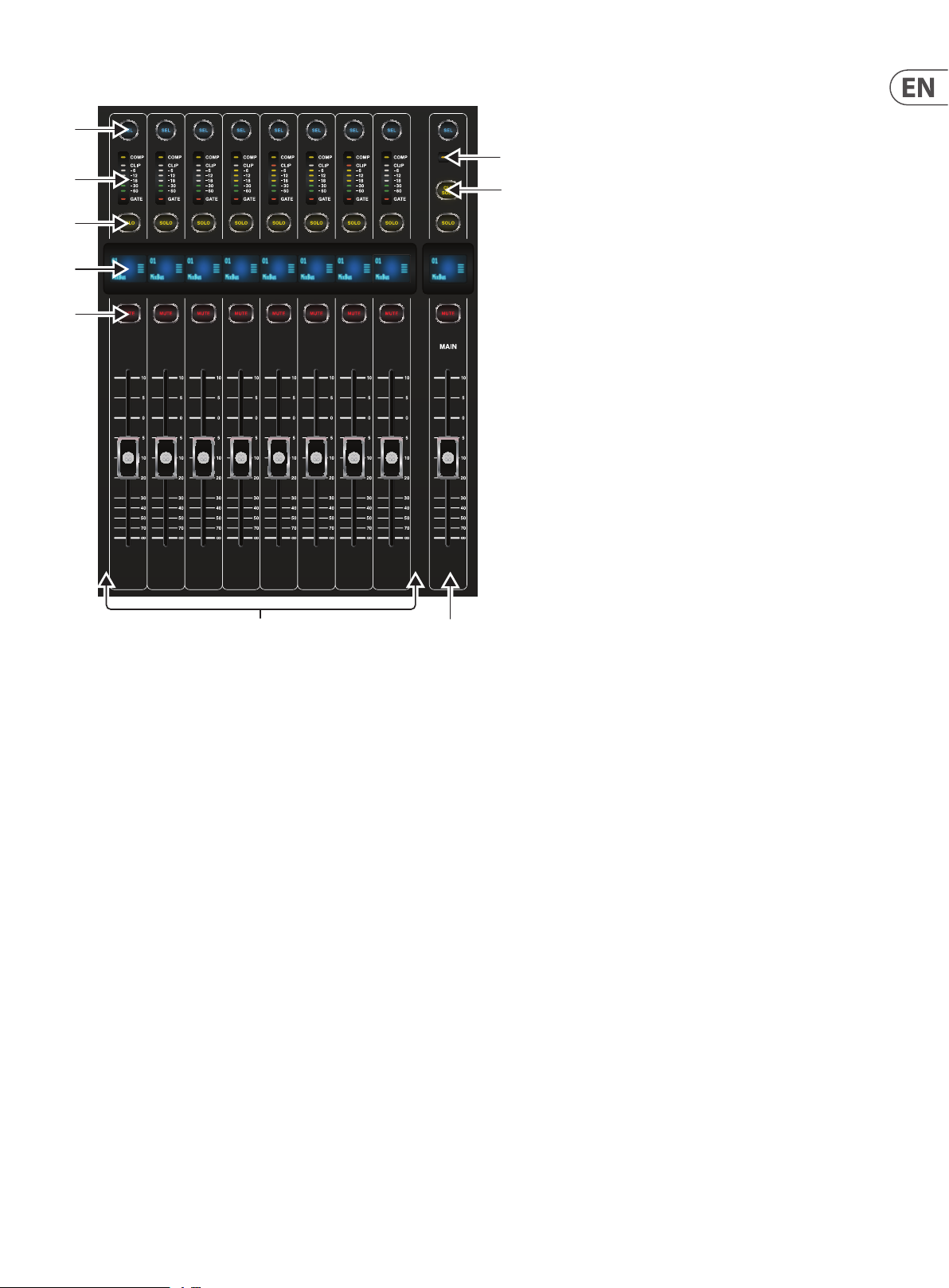
1.1 Channel Strip - Input Channels
(1)
(2)
(3)
(4)
(5)
(6)
(1) SEL Button
Press to select an input or bus (depending on which layer is active) and allow
it to be edited by the Channel Strip and Main Display.
(2) Channel Meter
This displays the signal level of the input or bus, depending on which layer
is active. The COMP and GATE LEDs light to indicate that compression and/or
noise gate are active.
(3) SOLO Button
Press to send the channel to the solo bus.
(4) Scribble Strip
Information such as channel number, input source and a graphic icon are
displayed here.
(5) MUTE Button
Press to mute the channel.
(6) Fader
Use the Midas PRO Motor Fader to adjust the channel output volume.
In Sends on Faders mode channel faders represent the send level from
channels to the currently selected output bus (see next page).
Page 13
13 DIGI TAL RACK MIXER M32R User Manual
1.2 Channel Strip - Group/Bus Channels
(1)
(2)
(3)
(4)
(5)
(6)
(7)
(8) (9)
(1) SEL Button
Press to select a DCA or bus (depending on which layer is active) and allow it
to be edited by the Channel Strip and Main Display.
(2) Channel Meter
This displays the signal level of the DCA or bus, depending on which layer is
active. The PRE LED lights to indicate that the bus is sourced pre-fader, while
the COMP LED lights to indicate that compression is active.
(3) SOLO Button
Press to send the channel to the solo bus.
(4) Scribble Strip
Information such as channel number, input source and a graphic icon are
displayed here.
(5) MUTE Button
Press to mute the channel.
(6) COMP
The COMP indicator will illuminate when compression is being applied to the
stereo output mix.
(7) CLR SOLO Button
Press to clear all sources assigned to the solo bus.
(8) Bus Faders
Use the Midas PRO Fader to adjust the channel volume or bus sends in Sends
on Faders mode. The faders will automatically display the current status as
layers and functions are changed.
(9) Fader
Use the Midas PRO Fader to adjust the output of the main bus.
Page 14
14 DIGI TAL RACK MIXER M32R User Manual
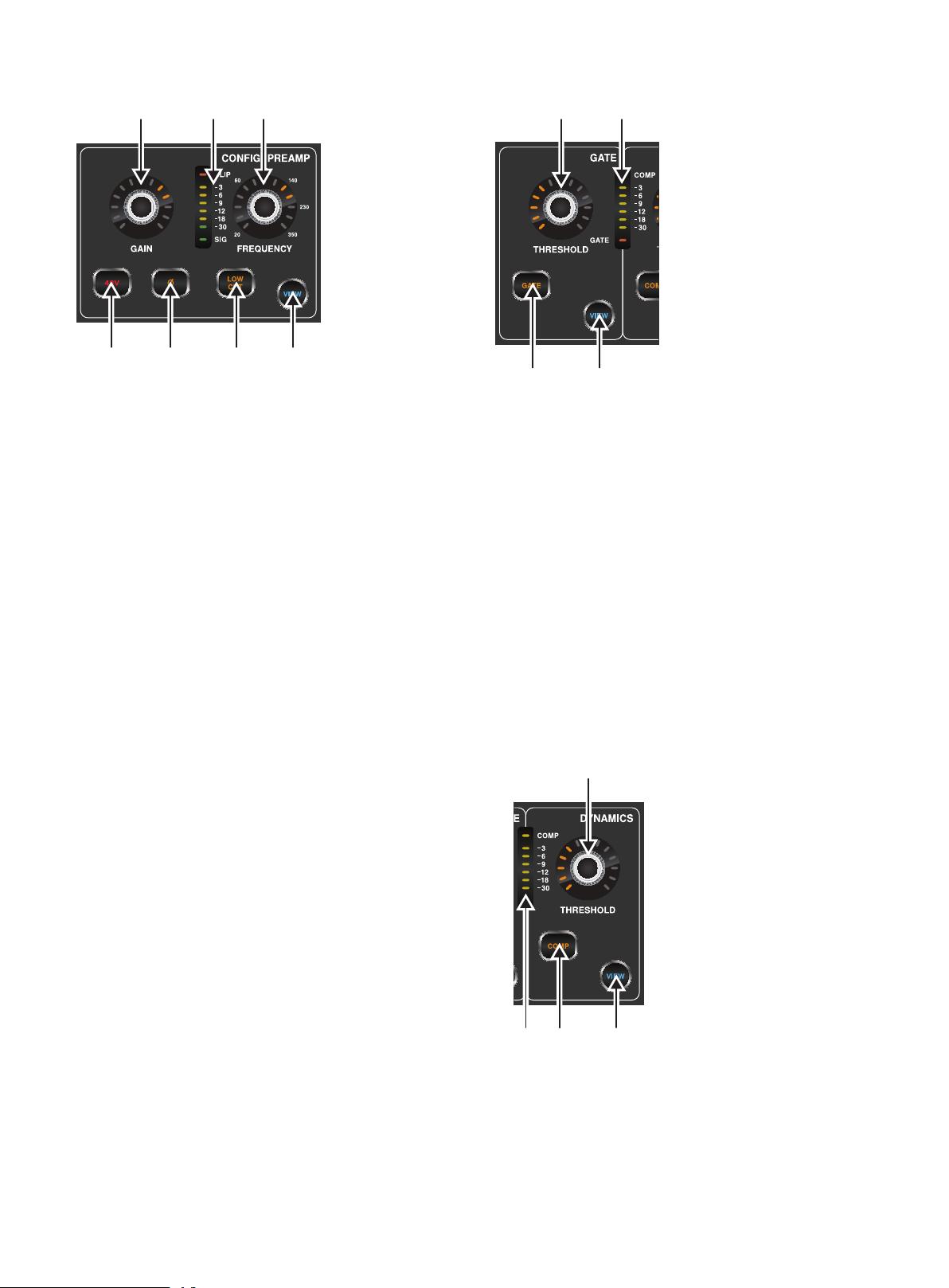
1.3 Cong/Preamp
(1) (2) (3)
(4) (5) (6) (7)
(1) GAIN Rotary Control
On a microphone preamplier, input gain varies the amount of amplication
applied to the microphone. Adjust the preamp gain for the selected channel
with the GAIN rotary control.
(2) LED Display
The LED display in the Cong/Preamp section illustrates the signal input
level for the selected channel. This is shown as a value between 0 dB and
-30 dB. When there is a signal present, but below -30 dB, the SIG LED is lit.
When the signal exceeds 0 dB the CLIP LED illuminates.
Please note that, when pressing the VIEW button, the signal input level
displayed on the Main Display shows a value of between 0 dB and -60 dB.
(3) FREQUENCY Rotary Control
The FREQUENCY rotar y control selects the frequency at which
the low cut lter begins to lter unwanted frequencies for the
selected channel. The lter is engaged by pressing the LOW CUT button
(see below).
Please note that the low cut lter is only available for the 32 primary
input channels.
(4) 48 V
Phantom power is a method for transmitting DC electric power through
microphone cables to operate microphones that contain ac tive electronic
circuitry. It is most commonly used with condenser microphones, though
many active direct boxes also use it. The technique is also used in other
applications where power supply and signal communication take place
over the same wires. Press the 48 V button to apply phantom power on the
selected channel’s physical input.
(5) Ø
An audio signal’s ‘phase’ refers to its position in a point of time along the
waveform cycle, with each cycle being 360°. Press the Ø button to reverse
the selected channel’s phase by 180°. This can be useful when using the
reverse phase function to cancel noise across more than one channel.
(6) LOW CUT
Press the LOW CUT button to engage the low cut lter for the
selected channel.
Please note that the low cut lter is only available for the 32 primary
input channels.
(7) VIEW
Press the VIEW button to access more detailed parameters on the
Main Display. See the section Main Display - cong for more details.
1.4 Gate
(1)
(2)
(3) (4)
(1) THRESHOLD Rotary Control
A noise gate is a device that is used to control the volume of an audio
signal. Often used in conjunction with a compressor (see DYNAMICS),
which attenuate signals above a certain threshold, noise gates attenuate
signals that register below the threshold. By turning the THRESHOLD
rotary control, the audio level at which the gate aects the signal
can be controlled.
(2) LED Display
The LED display illustrates when the Gate is functioning for the selected
channel by illuminating the red G ATE LED at the bottom of the display.
(3) GATE
Pressing the GATE button engages the noise gate for the selected channel.
(4) VIEW
Press the VIEW button to access more detailed parameters on the Main
Display. See the section Main Display - gate for more details.
1.5 Dynamics
(1)
(3) (4)
(2)
(1) THRESHOLD Rotary Control
Dynamic Range Compression, or just Compression is a device that is used
to control the volume of an audio signal. Often used in conjunction with a
noise gate (see GATE), which attenuate signals below a certain threshold,
compressors attenuate signals that register above the threshold. By turning
the THRESHOLD rotary control, the audio level at which the compressor
aects the signal can be controlled.
Page 15

15 DIGITAL RACK MIXER M32R User Manual
(2) LED Display
The LED display illustrates when the Dynamics are functioning for the selected
channel by illuminating the red COMP LED. The level of attenuation that is
being applied to the signal is shown as a value between 0 dB and -30 dB.
Please note that, when pressing the VIEW button, the attenuation level
displayed on the Main Display shows a value of between 0 dB and -60 dB.
(3) COMP
Pressing the COMP button engages the compressor for the selected channel.
(4) VIEW
Press the VIEW button to access more detailed parameters on the Main
Display. See the section Main Display - dyn for more details.
1.6 Equaliser
(1) (2) (3) (4)
(7)
(5)
(1) MODE Select Button and Display
Pressing the MODE button cycles through each of the EQ modes for the
currently selec ted frequency range. Each of the modes and the frequency
ranges to which they apply are listed below:
HCUT
A high-cut function which attenuates signals above the selected frequency.
HSHV
A high-shelving function which boosts or attenuates signals above the
selected frequency. Only available with the HIGH 2 - HIGH setting.
VEQ
A bell lter that provides a more ‘Vintage EQ’ sound. Available on all
frequency settings.
PEQ
A bell lter that provides a classic ‘Parametric EQ’ sound. Available on all
frequency settings.
(6)
LSHV
A low-shelving function which boosts or attenuates signals below the
selected frequency. Only available with the LOW 2 - LOW setting.
LCUT
A low-cut function which attenuates signals below the selected frequency.
NOTE: Low-Cut and High-Cut Modes do not have Gain and Width settings.
(2) WIDTH Rotary Control
The WIDTH rotary control determines the span of frequencies around that
specied by the FREQUENCY rotary control, which will be aected by
adjusting the GAIN control.
(3) FREQUENCY Rotary Control
Select the specic frequency to be adjusted with the FREQUENCY
rotary control. Each frequency can be adjusted between 20 Hz and 20 kHz.
The equaliser provides four discreet lter bands for input channels and even
six discreet bands for buses and matrices as follows:
7 - Individual Band Frequencies
HIGH
A band intended for high frequencies, with access to HCUT, HSHV, VEQ and
PEQ EQ modes.
HI MID
A band intended for high-mid frequencies, with access to VEQ and
PEQ EQ modes.
LO MID
A band intended for low-mid frequencies, with access to VEQ and
PEQ EQ modes.
LOW
A band intended for low frequencies, with access to LCUT, LSHV, VEQ and
PEQ EQ modes.
HIGH 2
Press HIGH and HI MID concurrently to access the HIGH 2 band of
any bus equaliser.
LOW 2
Press LOW and LO MID concurrently to access the LOW 2 band of any
bus equaliser.
(4) GAIN Rotary Control
Boost or attenuate the selected frequency by turning the GAIN rotary
control. The selected equaliser band is inactive when the Gain control is in
the centre position (0 dB).
(5) EQ Button
Engages the EQ function for the selected channel.
(6) VIEW
Press the VIEW button to access more detailed parameters on the
Main Display. See the sec tion Main Display - eq for more details.
Page 16

16 DIGITAL RACK MIXER M32R User Manual
1.7 Main Bus
(1) (2)
(3)
(1) LEVEL Rotary
Adjust the overall send level to the Mono Bus with the LEVEL rotary control.
(2) PAN/BAL Rotary
When the selected channel is assigned to the Stereo Bus, the PAN/BAL
rotary control adjusts the left to right positioning of the audio signal.
(3) MONO
Press the MONO button to assign the selected channel to the Main Mono/
Centre Bus.
(4) ST
Press the ST select button to assign the selected channel to the
Main Stereo Bus.
(5) VIEW
Press the VIEW button to access more detailed parameters on the
Main Display. See the section Main Display - main for more details.
(4) (4)
1.8.1 Operation
The M32R oers functionality for playing back uncompressed stereo WAV les,
and for recording any stereo signal in the console directly onto USB stick or
compatible USB hard drive. Note - multi-channel recording is only available via
the DN32-USB card.
To record to a USB stick, perform the following steps:
1. Plug a FAT-formatted (FAT12, FAT16, FAT32) USB stick into the USB port
as illustrated above.
2. Press the VIEW button in the RECORDER panel. This will then display a
graphic representation of an analogue tape deck on the Main Display
home tab.
3. On the cong tab you can selec t the source of the recording , the
default being the main L & R outputs.
4. Press the fth push encoder, labelled Record.
5. To adjust the volume during playback, press the AUX IN/USB button
next to the input channel faders, and adjust the volume using AUX
faders 7 & 8.
1.8 Recorder
(1)
(2)
(3)
(1) USB Port
Connect a USB stick to install rmware updates and to record per formances.
(2) ACCESS
The ACCESS LED illuminates to indicate that a USB stick is in place and is
being written to or read from.
(3) VIEW
Press the VIEW button to open the USB Recorder pages on the Main Display.
1.8.2 Firmware Updates
The M32R rmware can easily be updated by per forming the following steps:
• Download the new console rmware from the M32R product page onto the
root level of a USB thumb drive
• Plug the USB thumb drive into the front panel USB connector while the
console is turned o
• Hold the USB View button depressed while switching the console on.
While booting, the M32R will run a fully automatic rmware update,
which will take 2-3 minutes longer than the regular boot sequence
When no update le is available on the USB drive, or when it is corrupted,
the update mode will remain active, preventing the M32R from booting
regularly. Switch the console o and back on without holding the USB View
button to boot the console with the existing rmware.
The USB socket is not suitable for other non-memory USB devices like keyboards,
mice, lamps, etc.
Page 17

17 DIGITAL RACK MIXER M32R User Manual
1.9 Main Display (Summary)
(1)
(2)
(3) (3)
(4) (5)
(1) DISPLAY SCREEN
The controls in this section are used in conjunction with the colour screen in
order to navigate and control the graphical elements it contains.
By including dedicated push encoders that correspond to the adjacent
controls on the screen, as well as including cursor buttons, the user can
quickly navigate and control all of the colour screen’s elements.
The colour screen contains various displays that give visual feedback for
the operation of the console, and also allow the user to make various
adjustments not provided for by the dedicated hardware controls.
(2) MAIN/SOLO METERS
This triple 24-segment meter displays the audio signal level output from the
main bus, as well as the main centre or solo bus of the console.
(3) SCREEN SELECTION BUTTONS
These 10 illuminated buttons allow the user to immediately navigate
to any of the eight master screens that address dierent sections
of the console, plus the Mute Group and Utility functions. The sections that
can be navigated are:
HOME
The HOME screen contains an overview of the selected input or output
channel, and oers various adjustments not available through the dedicated
top-panel controls.
The HOME screen contains the following separate tabs:
home: General signal path for the selected input or output channel.
cong: Allows selection of the signal source/destination for the
channel, conguration of insert point, and other settings.
gate: Controls and displays the channel gate eect beyond those
oered by the dedicated top-panel controls.
dyn: Dynamics - controls and displays the channel dynamics eect
(compressor) beyond those oered by the dedicated top-panel controls.
eq: Controls and displays the channel EQ eect beyond those oered by
the dedicated top-panel controls.
sends: Controls and displays for channel sends, such as sends metering
and send muting.
main: Controls and displays for the selected channel’s output.
METERS
The METERS screen displays dierent groups of level meters for various
signal paths, and is useful for quickly ascertaining if any channels need
level adjustment. Since there are no parameters to adjust for the metering
displays, none of the metering screens contain any ‘bottom of the screen’
controls that would normally be adjusted by the six push encoders.
The METERS screen contains the following separate screen tabs, each
containing level meters for the relevant signal paths: channe l, mix bus,
aux/fx, in/out and rta.
ROUTING
The ROUTING screen is where all signal patching is done, allowing the
user to route internal signal paths to and from the physical input/output
connectors located on the console’s rear panel.
The ROUTING screen contains the following separate tabs:
home: Allows patching of physical inputs to the 32 input channels and
aux inputs of the console.
ou t 1-16: Allows patching of internal signal paths to the console’s
8 rear panel XLR outputs.
aux out: Allows patching of internal signal paths to the console’s six
rear panel ¼" / RCA auxiliary outputs.
p16 o ut : Allows patching of internal signal paths to the 16 outputs of
the console’s 16-channel P16 ULTRANET output.
card out: Allows patching of internal signal paths to the 32 outputs of
the expansion card.
aes50 -a: Allows patching of internal signal paths to the 48 outputs of
the rear panel AES50-A output.
aes50 -b: Allows patching of internal signal paths to the 48 outputs of
the rear panel AES50-B output.
xlr out: Allows the user to congure the XLR outs on the rear of the
console in blocks of four, from either local inputs, the AES streams,
or expansion card.
Page 18

18 DIGITAL RACK MIXER M32R User Manual
LIBRARY
The LIBRARY screen allows loading and saving of commonly-used setups for
the channel inputs, eects processors, and routing scenarios.
The LIBRARY screen contains the following tabs:
channel: This tab allows the user to load and save commonly used
combinations of the channel processing, including dynamics and EQ.
eects: This tab allows the user to load and save commonly used
eects processor presets.
routing: This tab allows the user to load and save commonly used
signal routings.
EFFECTS
The EFFECTS screen controls various aspects of the eight eects processors.
On this screen the user can select specic types of eec ts for the eight
internal eects processors, congure their input and output paths,
monitor their levels, and adjust the various eects parameters.
The EFFECTS screen contains the following separate tabs:
home: The home screen provides a general overview of the virtual
eects rack, displaying what eect has been inserted in each of the
eight slots, as well as displaying input/output paths for each slot and
the I/O signal levels.
fx 1-8: These eight duplicate screens display all of the relevant data for
the eight separate eects processors, allowing the user to adjust all
parameters for the selected eect.
SETUP
The SETUP screen oers controls for global, high-level functions of the
console, such as display adjustments, sample rates & synchronisation,
user settings, and network conguration.
The SETUP screen contains the following separate tabs:
global: This screen oers adjustments for various global preferences of
how the console operates.
cong: This screen oers adjustments for sample rates and
synchronisation, as well as conguring high-level settings for signal
path buses.
remote: This screen oers dierent controls for setting up the console
as a control surface for various DAW recording software on a connected
computer. It also congures the MIDI Rx/Tx preferences.
network : This screen oers dierent controls for attaching the console
to a standard Ethernet network. (IP address, Subnet Mask, Gateway.)
scribble strip: This screen oers controls for various customisation of
the console’s LCD scribble strips.
preamps: Shows the analogue gain for local mic inputs (XLR at the
rear) and phantom power, including setup from remote stage boxes
(e.g. DL16) connected via AES50.
card: This screen selects the input/output conguration of the installed
interface card.
MONITOR
Pressing the MONITOR but ton has the same eect as pressing the VIEW
button in the MONITOR panel, and is covered in detail in the MONITOR
section below.
SCENES
Pressing the SCENES button accesses the M32R’s automation functions.
This screen is covered in detail in the SCENES section of the
MAIN DISPLAY chapter.
MUTE GRP
The MUTE GRP screen allows for quick assignment and control of the
console’s six mute groups, and oers two separate functions:
Mutes the active screen during the process of assigning channels to
mute groups. This ensures that no channels are accidentally muted
during the assignment process during a live performance.
It oers an additional interface for muting/unmuting the groups
in addition to the dedicated mute group buttons at the bottom of
the console.
UTILITY
The UTILITY screen is a supplemental screen designed to work
in conjunction with the other screens that may be in view at any
particular moment. The UTILITY screen is never seen by itself, it always
exists in the context of another screen, and typically brings up copy,
paste and library or customisation func tions. For example:
• When you are adjusting the EQ of a channel, pressing the UTILITY
button will oer copying, pasting or loading func tionality, or saving of
EQ settings
• Pressing the UTILITY button while editing a channel’s
CONFIG/PREAMP screen will oer copying, saving or loading
preamp congurations
NOTE: Pressing the UTILITY button while holding the channel Select button is a
shortcut to editing the channel’s scribble strip display icon, naming or colour.
• On the ROUTING screen, pressing UTILITY will oer the ability to load
or save dierent presets of routing scenarios
• On the CUES, SCENES, SNIPPETS, PARAM SAFE and CHAN SAFE pages,
pressing UTILITY also oers dierent levels of import/export functions:
Cues: Utility allows importing or exporting complete Show data,
including all Cues, Scenes, Snippets and Safes to attached USB media.
Scenes: Utility oers selecting a number of scenes for exporting or
importing on attached USB media.
Snippets: Utility oers selecting a number of snippets for exporting or
importing on attached USB media.
Param Safes/Chan Safes: Utility allows setting/resetting the Safe
ags for a complete column of entries at once.
(4) PUSH ENCODERS
These six push encoders are used to adjust the various elements located
directly above them. Each of the six encoders can be pushed inward to
activate a button-press function. This function is useful when controlling
elements that have a dual on/o status that is best controlled by a button,
as opposed to a variable state that is best adjusted by a rotary control.
(5) UP/DOWN/LEFT/RIGHT NAVIGATION CONTROLS
The LEFT and RIGHT controls allow for left-right navigation among the
dierent pages contained within a screen set. A graphical tab display
shows which page you are currently on. On some screens there are
more parameters present than can be adjusted by the six push encoders
underneath. In these cases, use the UP and DOWN buttons to navigate
through any additional layers contained on the screen page. The LEFT
and RIGHT buttons are sometimes used to conrm or cancel conrmation
pop-ups.
Please refer to the MAIN DISPLAY chapter for more information on
these topics.
Page 19

19 DIGITAL RACK MIXER M32R User Manual
1.10 Monitor
(1) (2) (3) (4)
(1) MONITOR LEVEL Rotary Control
Adjust the level of the monitor outputs with the MONITOR LEVEL rotary
control. This will be the output device connected to the sockets in the
MONITOR / CONTROL ROOM OUT section on the rear panel.
(2) PHONES LEVEL Rotary Control
Adjust the level of the signal through the headphones or other output
devices connected via the headphone jack sockets located under the front of
the console.
(3) MONO
Press the MONO button to monitor the audio signal in mono.
(4) DIM
Press the DIM button to reduce the monitor volume by a predened
amount. The amount of attenuation can be dened via the Main Display
when the VIEW button is pressed.
(5) VIEW
Press the VIEW button to access more detailed parameters on the
Main Display.
1.10.1 Operation
The MONITOR section shares a Main Display screen with the TALKBACK section.
On this screen, only the monitor tab contains functionality which relates to the
MONITOR section. This tab controls various console options relating to the solo
bus, as well as the console’s control room outputs. These options include various
solo settings, speaker dimming, speaker delay, and a selection of sources for the
control room output.
To adjust the settings on the monitor tab, perform the following steps:
1. Adjust the rst push encoder to change the gain of the monitor signal.
This digital stage occurs as a rst preliminary level control, before the
top panel’s analogue-based monitor level control. A display above the
push encoder shows the currently set gain value in dB.
• A multi-segment level meter is displayed on the Main Display to allow
for proper gain staging of the monitor signal.
2. Adjust the second push encoder to scroll through the various solo
methods available to the console when audio is routed to the solo bus.
Available options include:
• Exclusive (last): In this mode, pressing another SOLO button
disengages the previous solo
• Solo Follows Select: When this method is selected, the audio of the
currently selec ted channel will automatically be sent to the solo bus.
Since a user will often select a channel to adjust its dedicated DSP
controls, this method is useful because the audio of the channel will
now already be feeding he solo bus where it can be monitored with
headphones in a live sound environment
• Select Follows Solo: When this method is selected, any channel that is
soloed will automatically become the currently selected channel
• Ch Solo AFL: The channel and select button do not have any correlation
to each other. When a channel’s SOLO button is pressed, its audio is sent
to the solo bus in ‘after-fader-listen’ mode, reecting the current level
of the channel fader and any channel DSP that has been applied.
The default setting for input channels is o for ‘pre-fader-listen’.
• MixBus Solo AFL: Selecting this method will set the mix bus solo to
post-fader
• DCA Solo AFL: Selecting this method will set the DCA solo to post-fader
• Use DIM for PFL: Selecting this option will apply DIM to all PFL signals
• Use Master Fader: This allows the main fader/MUTE button to control
the solo/mon output.
3. Tap the second encoder to select and assign the currently chosen
solo option.
4. Turn the third encoder to adjust the amount of digital delay that is
applied to the control room signal path. The display on the screen will
show the current amount of delay in feet, metres and milliseconds.
5. Tap the third encoder to toggle the delay function on or o.
TIP: The delay function is useful for aligning the sound of audio monitored
through headphones, or speakers used at front-of-house position with audio
that is coming from the stage location.
By delaying the control room audio, it can be brought into alignment with
the slightly-delayed audio that has to travel from the stage to the front-ofhouse position.
6. Adjust the fourth encoder to set the amount of volume reduction
that occurs when the control room bus has its DIM function enabled.
The amount of volume reduction ranges from -40 dB to 0 dB
(no change).
7. Tap the fourth encoder to toggle the DIM function on or o.
8. Turn the f th encoder to adjust the volume trim for the source currently
feeding the control room bus, allowing it to be level matched with the
SOLO bus. The amount of trim can be adjusted from -20 dB to +20 dB.
9. Tap the fth encoder to toggle the control room between mono and
stereo operation. This is very useful in a studio context for checking how
a mix sounds when played back on a mono speaker such as a cock radio.
10. Adjust the sixth encoder to select what specic signal source to monitor
in the control room. Choices include:
• O (no source) in the control room, when no SOLO is active
• LR Bus
• LR + C/M
• LR PFL (Pre-Fade Listen)
• LR AFL (After-Fade Listen)
• Auxiliary returns 5/6
• Auxiliary returns 7/8 (USB Recorder).
11. Tap the sixth encoder to activate the signal source that has been chosen.
Page 20

20 DIGITAL RACK MIXER M32R User Manual
1.11 Talkback
(1) (1) (3)
(1) & (2) - TALK A / B
Select the destination of the Talkback mic signal with either the TALK A or
TALK B buttons. Press the VIEW button in the MONITOR section to edit the
Talkback routing for A and B.
(3) TALK LEVEL Rotary Control
Adjust the level of the Talkback volume with the TALK LEVEL rotary control.
1.11.1 Operation
talkback Tab
The TALKBACK screen oers various adjustments for the talkback paths of the
console, such as destination of the talkback signal and more.
To adjust the various settings on the talkback tab, perform the
following steps:
1. The screen displays a multi-segment level meter showing the strength
of the talkback signal as it has currently been set. It also displays a
multi-segment gain reduction meter, showing the user how much
compression has been automatically applied to the talkback signal.
2. Tap the rst push encoder to enable the talkback circuit. The internal/
external talkback microphone will now transmit audio to the talkback
path’s assigned destination.
3. Adjust the third encoder to set the gain of the talkback signal. This is
an additional gain stage that follows the initial gain stage set by the top
panel TALK LEVEL control.
4. Tap the third encoder to toggle on/o the talkback circuits ‘auto-dim’
function. This function is useful in a studio setting, and will
automatically dim the control room outputs when the talkback circuit
is active. This prevents the talkback microphone from picking up too
much sound from the nearby studio monitors.
6. Tap the fourth encoder to activate any talkback destination when it
is currently selected. Multiple talkback destinations can be selected,
allowing the talkback signal to reach many destinations at the
same time.
7. Tap the fth encoder to toggle the dedicated top-panel talkback
buttons between latching and non-latching operation.
oscillator Tab
The oscilla tor tab oers controls for the console’s onboard oscillator, a very
handy tool that can be used for setting up PA systems and testing various
signal ow paths without the need for a live source feeding a microphone.
Settings include oscillator type, frequency, volume and routing destinations.
To adjust the various settings on the oscillator tab, perform the
following steps:
1. Adjust the rst push encoder to set the level of the onboard oscillator.
2. Tap the rst encoder to toggle the oscillator on or o.
• The Main Display shows a multi-segment level meter that shows
the current level of the oscillator.
3. Adjust the second encoder to set the frequency of the primary
onboard oscillator.
4. Adjust the third encoder to set the frequency of the alternate onboard
oscillator.
5. Tap the third encoder to alternate between Sine F1 and Sine F2.
6. Adjust the fourth encoder to select the type of oscillator to be used.
Choices include:
• Sine Wave
• Pink Noise
• White Noise.
7. Tap the fourth encoder to engage the selected oscillator type.
8. Adjust the sixth encoder to select a destination for the
onboard oscillator. Choices include:
• Mix Bus 1-16
• Main L Bus
• Main R Bus
• Main L+R Bus
• Main Centre / Mono
• Matrix Outputs 1-6.
9. Tap the sixth encoder to assign the selected oscillator destination.
5. Adjust the fourth encoder to scroll through the various talkback
destinations, which include:
• Mix Bus 1-16
• LR Bus
• Centre/Mono Bus.
Page 21

21 DIGITAL RACK MIXER M32R User Manual
1.12 Assign
1.12.1 Buttons 1-8
Assign the eight buttons to various parameters for instant access to commonly
used functions. Details can be found on the Main Display by pressing the VIEW
button (see below).
1.12.2 VIEW
This gives you more detailed access to the ASSIGN functions via the Main Display.
The ASSIGN screen allows setup for the four user-assignable rotary controls and
the eight user-assignable buttons. Using this screen the console operator can
assign three sets of 12 custom controls to be available for adjustment at all times.
Note: The M32R only has 8 Assign buttons, and no rotary controls.
However, the software still supports custom-assignable rotary control.
The ASSIGN screen contains the following separate tabs:
home: This screen provides a general overview of the 12 assigned controls
for all three control sets at the same time.
set A: This screen allows assignment of dierent console parameters to
the 12 custom controls for Set A.
set B: Works as described above, but for custom controls Set B
set C: Works as described above, but for custom controls Set C
HOME
The ASSIGN sc reen ’s home tab provides a visual overview of the 12 assigned
controls for all three sets at the same time.
The home tab oers visual feedback of the controls that have been assigned
to all three sets of custom controls, without having to bank between the three
sets one-by-one, or relying on abbreviated syntax shown in the custom control’s
dedicated LCD displays.
To adjust the various settings on the home tab, perform the following steps:
1. Turn any of the push encoders 1-5 to move screen focus to dierent
custom-assignable rotary controls and buttons in the A, B and C sets.
The controls currently selected with each of the four rotary controls are
highlighted with an orange outline.
2. Tap any of the push encoders 1-5 to switch to the edit screen for the
specic custom control that was highlighted on the home tab screen.
SET A, B & C
The set A, B & C tabs allow mapping of specic console parameters to the eight
assignable buttons and four assignable rotary controls. Using these screens the
user can map the exact parameters that are most useful to them to the desired
controls, in the desired order.
To adjust the various settings on the set A, B & C tabs, perform the
following steps:
1. Adjust the rst push encoder to select the colour used for the LCD
screens within that set. This is not applicable for the M32R since there
are no LCD screens in the Assign section.
2. Adjust the second push encoder to select to which of the 12 assignable
controls in the appropriate set you wish to map a parameter.
3. Adjust the third push encoder to scroll through a list of parameter
categories to which the selected assignable control can be mapped.
Choices for the buttons include:
• Not Assigned
• Jump to Page
• Mute Channel
• Inserts
• Eect Button
• MIDI
• Remote.
• Choices for the rotary controls include:
• Not Assigned
• Panorama
• Sends
• Dynamics
• FX Parameters
• MIDI
• Remote.
4. Tap the third push encoder to select the desired type of parameter.
5. Where applicable, tap/select the fourth, fth and sixth push encoders to
assign the specic parameter.
Page 22

22 DIGITAL RACK MIXER M32R User Manual
1.13 Fader Layer
(6)
(7)
(1)
(8)
(2)
(3)
(9)
(5)(4)
(1) INPUTS 1-8 / 9-16 / 17-24 / 35-32
Pressing one of these buttons selects either the channel 1-8 layer, the
channel 9-16 layer, the channel 17-24 layer, or the channel 25-32 layer on the
left-most eight fader strips.
(2) AUX IN / USB
Press to select the Aux In / USB Recorder layer on the left-most eight
fader strips.
(3) FX RET
Press to select the eects return layer on the left-most eight fader strips.
(4) BUS 1-8 / 9-16
Press one of these buttons to select either the Bus 1-8 layer or the Bus 9-16
layer on the left-most eight fader strips.
(5) FADER FLIP - SENDS ON FADER Button
Press to activate the M32R’s Sends on Fader function. This function aids
with the level setting of channels sent to any of the 16 Mix Buses. It is
only for channels assigned to Mix Buses 1-16, and does not work for DCA
groups, main or matrix buses. The Sends on Fader function works in two
convenient ways to cover the most obvious situations in a live environment:
When preparing a monitor mix for a specied musician
• Select the monitor bus (BUS 1-8 or BU S 9-16) that feeds the
musician’s stage monitor
• Press the Sends on Fader button, which will then ash
• Select one of the three input channel layers (INPUTS 1-16,
INPUTS 17-32, AUX IN / USB or BUS MAST)
• As long as Sends on Fader is active all faders in the input channels
section correspond to the send levels on the selec ted monitor
mix bus.
When checking or editing where a selected input signal is to
be sent
• Select the input channel in the left-hand section
• Press the Sends on Fader button, which will then ash
• Select either bus channel layer (BUS 1-8 or B US 9 -16)
• The bus faders now represent the send levels of the selected
input channel.
TIP: Sends on Fader can also be used for conveniently sending Bus or Main M/C
signals to Matrices.
(6) EM - DAW Remote Button
Press this button to enable remote control of your Digital Audio Workstation
software using the Group/Bus fader section controls. This section can
emulate HUI or Mackie Control Universal communication with your DAW.
(7) GROUP DCA 1-8
Press this button to select the Group DCA layer.
A DCA group is a grouping function, made possible by the console’s
digital operation, where individual input channels can be grouped
together and controlled with a single output fader on the right-hand
side of the console. Unlike the traditional sub-grouping function found
on analogue consoles, a DCA group does not combine the dierent input
channels into a common sub-mix. Instead, the individual input channels still
retain their original routing characteristics, but their level adjustments are
commonly controlled.
(8) BUS 1-8 / 9-16
Press one of these buttons to select either the Bus 1-8 layer or the Bus 9-16
layer on the right-most eight fader strips.
(9) MATRIX MAIN C
Press to select the Matrix and Main C layer on the right-most eight
fader strips.
Page 23

23 DIGITAL RACK MIXER M32R User Manual
2. Main Display
2.1 Main Display - Top Section
The top section of the Main Display permanently covers useful
status information. The top left corner shows the selected channel number,
its user-assigned name and the selected icon. The next block shows the
current scene number and name in amber, as well as the next upcoming scene.
The centre section displays the playback le name along with elapsed and
remaining time, and a recorder status icon. The next block to the right has
four segments to show the status of the AES50 ports A and B, the Card slot,
and the audio clock synchronisation source and sample rate. Small green square
indicators show proper connectivity. The rightmost block shows the console time,
which can be set under Setup - Cong.
2.1.1 Home
The HOME screen contains a high-level overview of the selected input or output
channel, and oers various adjustments not available through the dedicated
top-panel encoders.
The HOME screen is divided into the following tabs:
home: General signal path for the selected input or output channel.
cong: Allows selection of signal source/destination for the channel,
conguration of insert point, and other settings.
gate: Controls and displays the channel gate eect beyond those oered by
the dedicated top-panel encoders.
dyn: Controls and displays the channel dynamics eect (compressor) beyond
those oered by the dedicated top-panel encoders.
eq: Controls and displays the channel EQ eect beyond those oered by the
dedicated top-panel encoders.
sends: Controls and displays the channels sends, such as sends metering and
sends muting.
main: Controls and displays the selected channel’s output.
home
The home tab of the HOME screen displays a general signal path for the currently
selected input or output channel. It visually displays various parameters of the
input, gate, insert point, EQ, dynamics, output path and buses.
The home tab contains the following parameters (divided into two pages)
that can be adjusted using the six push encoders.
Page 1
1. Turn the rst push encoder to adjust the input gain (trim) of
the channel.
2. Tap the rst encoder to link the channel with its adjacent channel.
3. Adjust the second encoder to set the threshold of the channel
noise gate.
4. Tap the second encoder to toggle the channel noise gate in/out of the
signal path.
5. Adjust the third encoder to toggle the channel’s insert point between
pre-fader and post-fader status.
6. Tap the third encoder to toggle the channel insert in/out of the
signal path.
7. Adjust the fourth encoder to toggle the channel dynamics between
pre-EQ and post-EQ status.
8. Tap the fourth encoder to toggle the channel EQ in/out of the
signal path.
9. Adjust the fth encoder to set the threshold of the channel compressor.
10. Tap the fth encoder to toggle the channel compressor in/out of the
signal path.
11. Adjust the sixth encoder to pan the selected channel within the main
stereo output.
12. Tap the sixth encoder to assign the selected channel to the main
stereo output.
Page 2
1. Adjust the rst push encoder to select the console channel currently
controlled by the HOME screen.
2. Tap the rst encoder to toggle +48V phantom power on/o for the
currently selected input.
3. Tap the second encoder to toggle the phase ip on/o for the currently
selected channel.
4. Adjust the third encoder to select to which of the eight DCA groups the
currently selec ted channel will be assigned.
5. Tap the third encoder to assign the currently selec ted channel to the
selected DCA group.
6. Adjust the fourth encoder to select to which of the six mute groups the
currently selec ted channel will be assigned.
7. Tap the fourth encoder to assign the currently selected channel to the
selected mute group.
8. Tap the fth encoder to toggle solo on/o for the currently
selected channel.
9. Turn the sixth encoder to adjust the fader level for the currently
selected channel.
10. Tap the sixth encoder to toggle mute on/o for the currently
selected channel.
Page 24

24 DIGITAL RACK MIXER M32R User Manual
cong
The conguration tab allows selection of signal source/destination for the
channel, conguration of inser t point, and other settings, as well as conguration
of the channel delay.
The cong tab of input channels 1-32 contains the following parameters
that can be adjusted using the six push encoders:
1. Turn the rst push encoder to adjust the input gain (trim) of
the channel.
2. Tap the rst encoder to allow linking of the channel to the
adjacent channel.
3. Adjust the second encoder to set the low-cut frequency of the channel.
4. Tap the second encoder to toggle the low-cut lter in/out of the
signal path.
5. Adjust the third encoder to scroll among all of the possible sources for
the channel.
6. Tap the third encoder to select the currently highlighted source and
assign it to the channel.
7. Adjust the fourth encoder to set the amount of digital line delay applied
to the channel.
8. Tap the fourth encoder to toggle the delay in/out of the signal path.
9. Adjust the fth encoder to toggle the channel inser t between pre- and
post-EQ/compressor.
10. Tap the fth encoder to toggle the channel insert in/out of the
signal path.
11. Adjust the sixth encoder to scroll among the signal path choices for the
insert point.
12. Tap the sixth encoder to assign the selected signal path to the
insert point.
NOTE: Mix Bus channels do not have Gain, Low Cut, Phantom, Phase,
Source and Delay. But they do have a macro feature for setting all channel send
taps to the selected bus at once. As an example, this can be used for switching
all sends from Pre Fader to Post Fader or for ensuring that all channel taps
are consistent.
gate
The gate tab displays all aspects of the channel noise gate, and allows for very
deep control of the gate eect. Whereas the top panel’s dedicated GATE section
allows control of the gate’s threshold and in/out status, the gate tab oers many
more controls. This tab can be accessed directly by pressing the VIEW button in
the top panel GATE section.
The gate tab contains the following parameters, divided among two pages,
that can be adjusted using the six push encoders:
Page 1
1. Adjust the rst push encoder to set the input threshold of the gate.
2. Tap the rst encoder to toggle the noise gate in/out of the signal path.
3. Adjust the 2nd encoder to select between a gate, ducker, or 3 types
of expander.
4. Adjust the third encoder to set the attack time of the onset of the noise
gate eect.
5. Adjust the fourth encoder to set the hold time of the noise gate eect.
6. Adjust the fth encoder to set the release time of the noise gate,
controlling how quickly the gate opens up and lets the signal through.
7. Adjust the 6th encoder to determine the range of signal reduction.
Page 2
1. Push encoders 1 & 2 func tion the same on pages 1 & 2.
2. Adjust the fourth encoder to set the frequency of the key lter that can
be used to trigger the noise gate.
3. Tap the fourth encoder to toggle the key lter on/o, allowing a specic
frequency to control the gate.
4. Adjust the fth encoder to set the steepness of the EQ slope used in the
key lter.
5. Tap the fth encoder to send the key source to the solo bus, allowing
the key source to be monitored and evaluated.
6. Adjust the sixth encoder to select the specic key source to be used.
Choices include ‘Self ’ (the channel’s own signal), as well as any other
input/output of the console.
7. Tap the sixth encoder to assign the selected key source to the gate.
Page 25

25 DIGITAL RACK MIXER M32R User Manual
dyn
The dynamics tab displays all aspects of the channel compressor, and allows for
very deep control of the eect. Whereas the top panel’s dedicated compressor
section allows control of the threshold and in/out status, the dyn tab oers many
more controls. This tab can be accessed directly by pressing the VIEW button in
the top panel DYNAMICS section.
The dyn tab contains the following parameters that can be adjusted using
the six push encoders:
Page 1
1. Adjust the rst push encoder to set the input threshold of
the compressor.
2. Tap the rst encoder to toggle the compressor in/out of the signal path.
3. Adjust the second encoder to set the ratio of the compressor.
4. Tap the second control to switch the channel dynamics eect between
compression and expansion.
5. Adjust the third encoder to set the attack time of the compressor eect.
6. Tap the third encoder to switch the compressor bet ween Peak and RMS
(root mean squared) mode, where the average level of the signal is
evaluated more than any specic peak of the channel material.
• PEAK: A peak-sensing compressor responds to the instantaneous
level of the peak signal. While providing tighter peak control, peak
sensing might yield very quick changes in gain reduction, more
evident compression, or sometimes even distortion. This mode is
suitable for control/limiting of dynamic material.
• RMS: In this mode, the compressor applies an average function
on the input signal before its level is compared to the threshold.
This allows a more relaxed compression that also more closely
relates to our perception of loudness. Sharp dynamic transients
will be less aected in this mode. This mode is good for controlling
levels in a mix.
7. Turn the fourth encoder to adjust the hold time of the compressor.
• Hold time is a parameter not often found on commercial units,
but is very useful. If a compressor is set to use a very fast attack/
release time, audible distor tion can occur, because the compressor
is trying to work on individual waveform cycles of the signal
instead of the sound envelope as a whole. The Hold parameter
works around this issue by providing a short delay. This delay
prevents the compressor from releasing until a certain period of
time has elapsed.
8. Tap the fourth encoder to switch between Linear and Logarithmic
modes for the compressor. Following are some brief descriptions of
those dierent modes:
LOG: This mode is used in many well-respected compressors and is the
natural result of more recent analogue units employing logarithmic
side chains and resistor/capacitor time constants. The exponential/
dB law has some interesting characteristics. Firstly the time taken to
complete a compression event tends to stay the same however large
the dynamic signal excursion is. Also, since the peak rate of gain change
increases with dynamic excursion, the resulting harmonic content due
to compress tends to follow the loudness of the signal in a way that
the ear expects. This helps to mask the eec t of the compressor and
thus provides the most forgiving solution, being tolerant of diering
timing settings and signal material. This makes it the best choice
for general compression use and overall dynamic control of complex
musical signals.
LINEAR: In this mode, the rate if gain change is constant (as set by the
timing controls). Therefore the greater the signal dynamic excursion,
the longer the compressor will take to complete a gain change.
Also, since the total time that the compressor spends in attack or decay
is proportional to the size of the gain excursion, the harmonic content
of the compression artefact will seem to reduce in frequency content,
the louder the signal excursion. This type of compressor is useful for
generating dynamic sound eects because the sonic character of the
compressor is much more aected by time control settings and signal
material than the exponential type.
9. Adjust the fth encoder to set the release time of the compressor.
10. Tap the 5th encoder to engage the “auto” function, which automatically
optimizes advanced parameters such as attack, hold and release.
11. Adjust the sixth encoder to set the makeup gain of the compressor;
useful when the compression eect has reduced the overall signal level
of the channel too much.
Page 2
1. The 1st encoder still engages and adjusts the threshold.
2. Adjust the 2nd encoder to set the mix of the compressor. Normally this
would be set to 100%, but by reducing the mix level, an eect called
‘parallel compression’ can be achieved, allowing some of the signal to
pass through uncompressed.
3. Adjust the third encoder to set the steepness of the compressor knee
angle between ve separate settings. Adjust this control to switch
between a harder sounding, or more transparent compressor eect.
4. Tap the third encoder to move the compressor eect before or after the
EQ in the channel signal path.
5. Adjust the fourth encoder to set the frequency of the key lter that can
be used to trigger the compressor.
6. Tap the fourth encoder to toggle the key lter on/o, allowing a specic
frequency to control the compressor.
7. Adjust the fth encoder to set the steepness of the EQ slope used in
the compressor.
8. Tap the fth encoder to send the key source to the solo bus, allowing
the key source to be monitored and evaluated.
9. Adjust the sixth encoder to select the specic key source to be used,
Choices include ‘Self ’ (the channel’s own signal), as well as any other
input/output of the console.
10. Tap the sixth encoder to assign the selected key source to
the compressor.
Page 26

26 DIGITAL RACK MIXER M32R User Manual
eq
The eq tab displays all aspects of the channel EQ, and also displays a detailed
visual graphic of the current EQ curve. This tab can also be accessed directly by
pressing the VIEW button on the top panel EQUALISER section.
1. If the currently selected channels is an input, the channel EQ contains
four bands, with various aspects of each band adjusted by push
encoders 2-5.
2. If the currently selected channel is a bus, the channel EQ contains six
bands, with various aspects of each band adjusted by encoders 1-6.
3. On the EQ screen, the various push encoders are always tied to an aspect
of the frequency adjustment, and the Up/Down navigation controls
are used to toggle between the 4 bands. The 6th encoder also toggles
which band is active.
• Adjust the 1st encoder to set the low cut frequency.
• Tap the 1st encoder to engage the low cut.
• Adjust the 2nd encoder to adjust the frequency for the selected
band. All 4 bands can be shif ted between 20 Hz and 20 kHz, so the
band labeled ‘Low’ can actually be used to adjust mids, etc.
• Tap the 2nd encoder to determine whether the RTA operates as a
bar graph or spectrograph.
• Adjust the 3rd encoder to set the amount of cut or boost for the
selected band.
• Tap the 3rd encoder to set the RTA as pre or post, depending if
you want to monitor the incoming signal or the eects of the
EQ adjustment.
• Adjust the 4th encoder to set the bandwidth (Q) of the selected
band. This is only available if the band is set to PEQ or VEQ.
• Tap the 4th encoder to reset the selected EQ band.
• Adjust the 5th encoder to determine the mode of the selected
band. The following options are available:
• Low cut
• Low shelf
• PEQ (standard parametric)
• VEQ (vintage style)
• High shelf
• High cut
• Tap the 5th encoder to reset all of the EQ bands.
• Adjust the 6th encoder to select the frequency band.
• Tap the 6th encoder to activate the EQ.
sends
The sends tab displays and controls all aspects of the channel sends to the
16 mix buses. Compared to the dedicated top panel send controls, this screen
oers additional functions, such as send muting and simultaneous metering of
the selected channel’s 16 sends. This tab can also be accessed directly by pressing
the VIEW button in the top panel BUS SEND section.
The sends tab contains the following parameters that can be adjusted using
the six push encoders:
Page 1
1. Adjust the rst push encoder to set the level for the rst send of the
currently selected four-send group.
2. Tap the rst encoder to mute the rst send of the currently selected
four-send group.
3. Repeat the process with the nex t three encoders for the remaining
three sends in the currently selected four-send group.
4. Adjust the sixth encoder to select which four sends to control with the
rotary controls, shifting focus two sends at a time.
5. Tap the sixth encoder to select which four sends to control with the
rotary controls, shifting focus four at a time.
Page 2
1. Adjust the rst push encoder to select from where in the signal chain
the send is tapped, for the rst two sends of the currently focused four
sends. Options include:
• Pre-EQ
• Post-EQ
• Pre-fader
• Post-fader
• Sub-group.
2. Adjust the third encoder to perform the same operation for the second
two sends of the currently focused four sends.
3. Adjust the sixth encoder to select which four sends to control with the
rotary controls, shifting focus two sends at a time.
4. Tap the sixth encoder to select which four sends to control with the
rotary controls, shifting focus four at a time.
Page 27

27 DIGI TAL RACK MIXER M32R User Manual
main
The main tab displays and controls all aspects of the main bus assignments.
The main tab contains the following parameters that can be adjusted using
the six push encoders:
1. Adjust the rst push encoder to pan the selected channel within the
main stereo output.
2. Tap the rst encoder to assign the selected channel to the
main stereo output.
3. Turn the second encoder to adjust the level of the currently selected
channel within the mono (centre) bus.
4. Tap the second encoder to assign the selected channel to the mono
output signal path. Use this function when craf ting an LCR mix, as
opposed to a mono or stereo mix.
5. Tap the fth encoder to solo/unsolo the currently selected channel.
6. Adjust the sixth encoder to set the fader level for the currently
selected channel.
7. Tap the sixth encoder to mute/unmute the currently selected channel.
2.2 Meters
mix bus
• Level meters, fader levels and gain reduction meters for the 16 bus masters
• Level meters, fader levels and gain reduction meters for the six
matrix outputs
• Level meters, fader levels and gain reduction meters for the stereo main bus
and the mono bus.
aux/fx
• Level meters for the six auxiliary sends
• Level meters and fader levels for the eight auxiliary returns
• Level meters and fader levels for the four stereo eects returns.
in/out
The 32 input channels
The eight auxiliary returns
• The six auxiliary sends
• The two rear panel digital outputs
• Monitor outputs
• The 16 rear panel analogue outputs
• The P16 ULTRANET outputs.
rta
The rta tab shows details of the M32’s Real Time Analyser - a real-time
spectrum analyser that displays details of the audio signal on the selected
signal path. The M32 features both bar graph and spectrograph with a
10-second window, that are displayed on the Main Display, and can be used in a
variety of applications. The frequency resolution of both analysers is 100 bands,
with constant relative bandwidth from 20 Hz to 20 kHz. Hence they are three
times more detailed than typical third-of-an-octave RTAs. Both graphs can be
visualised in a separate Meter screen, on top of each channel parametric EQ and
on the FX rack graphic EQ screens.
RTA Source
Depending on the application the analyser input signal can be taken from the
selected channel itself, any other pre-dened channel or dynamically depending
on monitor source signals (i.e. Main/Solo). When EQ-ing a main PA system
for example, the Graphic EQ may be inserted in Main LR, while the analyser signal
may come from a dedicated measuring mic input channel. Select the source
signal using the sixth push encoder.
The METERS screen displays dierent groups of level meters for various signal
paths on the console, and is useful for quickly ascertaining if any channels
need level adjustment. Since there are no parameters to adjust for the
metering displays, none of the metering screens (with the exception of the
rta tab; see below) contain any ‘bottom-of-screen’ controls that would normally
by adjusted by the six push encoders.
The METERS screen contains the following separate screen tabs, each containing
level meters for the following signal paths:
channel
• Level meters and fader levels for the 32 input channels.
Solo Priority
When switched on, the selected RTA source signals will be replaced with the
monitor solo bus whenever a channel solo is active.
TIP: This option might be useful, if you wish to analyse a group of
channels concurrently, or if you have a xed signal on the RTA that needs to be
replaced only temporarily with some other channel’s signal.
Page 28

28 DIGITAL RACK MIXER M32R User Manual
Pre / Post
The analysers can tap their input signals from pre- or post-EQ, allowing you to
see the impact of your EQ in that channel. Tap the fth push encoder to toggles
between the two.
Gain
When engaged, the Auto Gain function simplies adjusting the analyser views
and ensuring meaningful readings. In most cases it should be switched on.
When switched o, the RTA gain can be set manually using the push encoder,
which may be necessary for comparing absolute frequency band levels
between dierent channels. Tap the fourth push encoder to engage the
Auto Gain function.
EQ Overlay
When using the analysers on top of the channel EQ plot or over the graphic
EQ screens, the meter’s opacity can be adjusted to your liking. Something around
50% is typically a good starting point. Turn it down to 0% with the fth push
encoder if you don’t need to see the RTA on top of the channel EQ or graphic
EQ screens.
RTA On Channel EQ View
The channel EQ RTA function will always display the respective channel’s
frequency distribution, independent from the RTA Source denition. Use the EQ
Overlay control for adjusting the amount of RTA on top of the EQ plot. Default
preferences when opening any channel EQ view can be set to ‘Pre-EQ’ (o is
Post-EQ) and ‘Spectrograph’ (o is bar graph). They can however be overruled on
the respective EQ page.
RTA On Graphic EQ View
The Graphic EQ RTA function will always display the respective FX slot’s frequency
distribution, independent from the RTA Source denition, unless the ‘Use RTA
Source’ mark is ticked. Use the EQ Overlay control for adjusting the amount of RTA
on top of the GEQ sliders. Default preferences when opening any GEQ view can
be set to ‘Post-GEQ’ (o is pre-graphic EQ) and ‘Spectrograph’ (o is bar graph).
They can however be overruled on the respective GEQ page.
2.3 Routing
The ROUTING screen is where all signal patching is done, allowing you to route
internal signal paths to and from the physical input/output connec tors located
on the M32R’s rear panel.
The ROUTING screen contains the following separate tabs:
home: Allows patching of physical inputs to the 32 input channels and
auxiliary inputs of the console.
ou t 1-16: Allows patching of internal signal paths to the console’s
8 rear-panel XLR outputs.
aux out: Allows patching of internal signal paths to the console’s six
rear-panel ¼“/RCA auxiliary outputs.
p16 o ut : Allows patching of internal signal paths to the 16 outputs of
the console’s 16-channel P16 ULTRANET output.
card out: Allows patching of internal signal paths to the 32 outputs of
the DN32-USB card.
aes50 -a: Allows patching of internal signal paths to the 48 outputs of
the rear-panel AES50-A output.
aes50 -b: Allows patching of internal signal paths to the 48 outputs of
the rear-panel AES50-B output.
xlr out: Allows patching of internal signal paths to the XLR out
connections on the rear.
None of the ROUTING screen’s tabs contain a secondary level of functions.
When routing audio, the Up/Down navigation controls do not need to be used.
home
The ROUTING sc reen’s home tab allows the user to patch the M32R’s physical
rear-panel inputs to the 32 input channels and auxiliary inputs of the console.
As a default, the M32R maps its 16 rear panel inputs to the rst 16 channel inputs
that are accessed on input fader layers one and two, and maps the rear-panel
line-level (auxiliary) inputs to the ‘Aux In 1-6 / USB REC’ fader level.
However, the home tab of the ROUTING screen can be used to change this
default assignment and cross-patch dierent physical inputs to dierent
channel inputs, in banks of eight channels at a time. This allows the user to
create a custom layer of channel inputs that diers from the order that the
sources are plugged into the rear panel, and is easier than physically re-patching
audio cables.
To assign various inputs to the M32R’s input channels, perform the
following steps:
1. Adjust the rst push encoder to select which 8-channel audio input
source feeds input channels 1-8 of the console. As the control is rotated,
the currently selected input will be highlighted in the vertical list
of choices.
2. When the desired 8-channel source is selected, push the rst
push encoder to connect the currently selected 8-channel source.
The selected source now feeds input channels 1-8 of the console.
3. Input choices that can be assigned include:
• Local 1-8
• Local 9-16
• Local 17-24
• Local 25-32
• AES50-A 1-8
• AES50-A 9-16
• AES50-A 17-24
• AES50-A 25-32
• AES50-A 33-40
• AES50-A 41-48
• AES50-B 1-8
• AES50- B 9 -16
• AES50 -B 17-24
• AES50-B 25-32
• AES50-B 33-40
• AES50-B 41-48
• Card 1-8
• Card 9-16
• Car d 17-24
• Card 25-32.
Page 29

29 DIGITAL RACK MIXER M32R User Manual
4. To assign an 8-channel source from the other input channels of the
console (9-16, 17-24, 25-32), simply repeat the process above, using the
other four push encoders on the same screen.
5. Choices for Aux 1-4 include:
• Aux Ins
• Local 1-2
• Local 1-4
• Local 1-6
• AES50A 1-2
• AES50A 1-4
• AES50A 1-6
• AES50B 1-2
• AES50B 1-4
• AES50B 1-6
• Car d 1-2
• Card 1-4
• Card 1-6.
out 1-16
The ROUTING screens o ut 1-16 tab allows the user to patch the M32R’s various
internal signal paths to the 8 analogue XLR outputs that are located on the
console’s rear panel.
The M32R allows for many dierent kinds of output signal paths, and this screen
is where these outputs are assigned to a physical rear panel output, so that the
signal path can be patched to their eventual destination, such as front-of-house
PA speakers or a powered stage monitor.
To assign the various output paths to the rear panel XLR outputs, per form
the following steps:
1. Adjust the rst push encoder to select to which of the 8 rear panel
analogue outs you wish to assign an output signal path.
2. Adjust the third encoder to select an output path category.
These include:
• O
• Main (LRC) Mix
• Mix Bus Outputs
• Matrix Outputs
• Direct Outs
• Moni tor.
3. Adjust the fourth encoder to select a specic output path, including:
• O
• Main L
• Main R
• Main C/M
• Any of the 16 Mix Outputs
• Any of the six Matrix Outputs
• Any of the 32 Direct Outputs
• Any of the eight Auxiliary Outputs
• Any of the FX Direct Outputs
• Monitor L
• Monitor R
• Talkback.Tap the fourth encoder to assign the selected output path,
completing the process.
• Adjust the fth encoder to select the signal tap point for the
output assignment. This determines where in the audio signal path
the source is ‘tapped’ as it is sent to the physical rear panel output.
The available signal tap points include:
• IN/LC
• IN/LC +M
• PreEQ
• PreEQ +M
• PostEQ
• PostEQ +M
• PreFdr
• PreFdr +M
• Post Fader.
4. Tap the fth encoder to assign the selected signal tap point.
5. Turn the sixth encoder to adjust the amount of digital line delay applied
to the output path as it is sent to the rear panel physical output. As the
amount of delay is adjusted, the current delay time is displayed in three
dierent units of measurement: feet, metres and milliseconds.
6. Tap the sixth encoder to toggle delay on/o. The Delay label illuminates
when the delay is inserted into the signal path.
TIP: Applying a delay to an output signal is typically done when the console is used
in a ‘multi-zone’ PA speaker setup, where some PA speakers are located near the
stage, and a second set of speakers is located further back within the audience.
By applying an appropriate amount of delay only to the speakers located near the
stage, the audience hears the audio from all speakers at the same time, ensuring
maximum time-alignment and sound quality. The M32 assumes an operating
temperature of 20°C/68°F when calculating the delay times.
aux out
The ROUTING sc reen’s aux out tab allows the user to patch an internal signal
path (such as a mix output used as an eects send) to the six separate ¼"/RCA
auxiliary outputs.
Since these six outputs can have a wide variety of signal paths assigned to them,
they can be used for a wide variety of tasks, such as:
1. Feeding an external eects processor when the internal eects
are insucient.
2. Patching a specic console signal path to an outboard recorder.
3. Feeding the analogue or digital audio inputs of a nearby video recorder.
To make an assignment as described above, perform the following steps:
1. Adjust the rst push encoder to select to which auxiliary outputs to
assign a source. Choices include
• Aux Out 1
• Aux Out 2
• Aux Out 3
• Aux Out 4
• Aux Out 5
• Aux Out 6
• AES/EBU (Digital) Out L
• AES/EBU (Digital) Out R.
2. Adjust the third encoder to select for coarse range:
• Insert
• Main (LRC)
• Mix Bus
• Matrix
• Direct Out
• Moni tor.
Page 30

30 DIGITAL RACK MIXER M32R User Manual
3. Adjust the fourth encoder to select a specic signal path to feed the
selected physical output. Choices include:
• Insert Point
• Main L
• Main R
• Main C/M
• Any of the 16 Mix Outputs
• Any of the six Matrix Outputs
• Any of the 32 Direct Outputs
• Any of the eight Auxiliary Outputs
• Any of the FX Direct Outputs
• Monitor L
• Monitor R
• Talkback.
4. Tap the fourth encoder to assign the selected output path, completing
the process.
5. Adjust the fth encoder to select the signal tap point for the output
assignment. Choices include:
• IN/LC
• IN/LC +M
• PreEQ
• PreEQ +M
• PostEQ
• PostEQ +M
• PreFdr
• PreFdr +M
• Post Fader.
6. Tap the fth encoder to complete the signal tap point assignment.
7. Tap the 6th encoder to enter iQ Setup
• Adjust the 1st encoder to select a P16 channel.
• Adjust the 3rd encoder to select the iQ speaker assigned to the
selected channel. Press the encoder to conrm.
• Adjust the 4th encoder to select an EQ Preset, then press the
encoder to conrm.
• Adjust the 5th encoder to select a Sound Prole that the iQ speaker
will model, then press the encoder to conrm.
• Press the 6th encoder again to return to the P16 tab.
p16 out
The ROUTING sc reen’s p16 out tab allows the user to route various console signal
paths to the rear panel P16 ULTRANET output. This output allows for 16 channels
of audio to be sent, in digital form, to various accessories such as a personal
monitoring distribution box.
Using the p16 o ut routing screen, the user can congure the P16 output to carry
not only the main LR mix, but also various audio ‘stems’ of audio material sources
from a bus send mix, such as a stereo drum mix, stereo keyboards, guitars,
bass, vocals, etc. Musicians on stage would then be free to each craft their own
personal mix of these musical stems, all delivered from the FOH position to stage
over a single Ethernet cable.
To select which audio signals are sent to the P16 bus, perform the
following steps:
1. Adjust the rst push encoder to select for which of the 16 channels in
the P16 bus you wish to select an audio source.
2. Adjust the third encoder to select a category of audio source to send to
the currently selected P16 channel. These categories include:
• Insert
• Main (LRC)
• Mix Bus
• Matrix
• Direct Out
3. Monitor.Adjust the fourth encoder to select which specic signal path to
feed to the currently selected P16 output. Choices include:
• O
• Main L
• Main R
• Main C/M
• Any of the 16 Mix Outputs
• Any of the six Matrix Outputs
• Any of the 32 Direct Outputs
• Any of the eight Auxiliary Outputs
• Any of the FX Direct Outputs
• Monitor L
• Monitor R
• Talkback.
4. Tap the fourth encoder to assign the selected output path, completing
the process.
5. Adjust the fth encoder to select the signal tap point for the output
assignment. This determines where in the audio signal path the source
is ‘tapped’ as it is sent to the P16 output. The available signal tap
points include:
• IN/LC
• IN/LC +M
• PreEQ
• PreEQ +M
• PostEQ
• PostEQ +M
• PreFdr
• PreFdr +M
• Post Fader.
6. Tap the fth encoder to complete the signal tap point assignment.
card out
The ROUTING sc reen’s card out tab allows the user to patch various signal paths
to the physical inputs and outputs on the DN32-USB card. The card’s signal path
provides 32 channels of inputs and 32 channels of outputs. The 32 card inputs can
be used as alternative sources for the two input fader layers, switchable in banks
of eight.
Page 31

31 DIGITAL RACK MIXER M32R User Manual
To assign an output path to the option card, perform the following steps:
1. Adjust the rst push encoder to select an 8-channel signal path that will
be sent to the rst eight channels of the card. Choices include:
• Local 1-8 • AES50-B 25-32
• Local 9-16 • AES50-B 33-40
• Local 17-24 • AES50-B 41-48
• Local 25-32 • Card 1-8
• AES50-A 1-8 • Card 9-16
• AES50-A 9-16 • Car d 17-24
• AES50-A 17-24 • Card 25-32
• AES50-A 25-32 • Out 1-8
• AES50-A 33-40 • Out 9 -16
• AES50-A 41-48 • P16 1-8
• AES50-B 1-8 • P16 9-16
• AES50- B 9 -16 • Aux 1-6/Mon.
• AES50 -B 17-24
2. Tap the rst encoder to assign the selected output path,
completing the process.
3. Repeat the process with encoders 2-4 to select output paths for the
other 24 channels or card outputs.
aes50-a / aes50-b
The ROUTING screens aes50-a and aes50-b tabs allow the user to patch
various console output paths to the outputs of the dual AES50 connectors.
These connectors can feed other AES50-equipped devices, such as a digital stage
box or standalone multi-track recorder.
The M32R contains two separate AES50 connectors, labelled A and B. These dual
connectors allow for an increased level of exibility in networking the console to
various AES50-based equipment.
Each of the two AES50 tabs contains the same following sets of parameters
that can be adjusted. To assign various console signal paths to the AES50
connectors, perform the following steps:
1. Adjust the rst push encoder to select an 8-channel signal path that
will be sent to the rst eight channels of the AES50 connector’s output.
Choices include:
• Local 1-8 • AES50-B 25-32
• Local 9-16 • AES50-B 33-40
• Local 17-24 • AES50-B 41-48
• Local 25-32 • Card 1-8
• AES50-A 1-8 • Card 9-16
• AES50-A 9-16 • Car d 17-24
• AES50-A 17-24 • Card 25-32
• AES50-A 25-32 • Out 1-8
• AES50-A 33-40 • Out 9 -16
• AES50-A 41-48 • P16 1-8
• AES50-B 1-8 • P16 9-16
• AES50- B 9 -16 • Aux 1-6/Mon.
• AES50 -B 17-24
xlr out
The ROUTING sc reen’s xlr out tab, much like the ou t 1-16 tab, allows the user to
patch the M32R’s various internal signal paths to the 8 analogue XLR outputs that
are located on the console’s rear panel. This tab, however, allows the XLR outputs
to be patched in blocks of four, rather than individually. Also, on this screen it is
only possible to route the signal to its absolute destination, rather than choosing
the signal path. The available destinations will dier depending on the block
selected. Destinations include:
Block 1-4 / Block 9-12 Block 5-8 / Block 13-16
• Local 1-4 • Local 5-8
• Local 9-12 • Local 13-16
• Local 17-20 • Local 21-24
• Local 25-28 • Local 29-32
• AES50-A 1-4 • AES50-A 5-8
• AES50-A 9-12 • AES50-A 13-16
• AES50-A 17-20 • AES50-A 21-24
• AES50-A 25-28 • AES50-A 29-32
• AES50-A 33-36 • AES50-A 37-40
• AES50-A 41-44 • AES50-A 45-48
• AES50-B 1-4 • AES50-B 5-8
• AES50- B 9 -12 • AES50-B 13-16
• AES50 -B 17-20 • AE S50 -B 21-24
• AES50-B 25-28 • AES50-B 29-32
• AES50-B 33-36 • AES50 -B 37- 40
• AES50-B 41-44 • AES50-B 45-48
• Card 1-4 • Card 5-8
• Card 9-12 • Card 13-16
• Car d 17-20 • Ca rd 21-24
• Card 25-28 • Car d 29-32
• Out 1-4 • Out 5-8
• Out 9 -12 • Out 13-16
• P16 1-4 • P16 4-8
• P16 9-12 • P16 13-16
• Aux 1-4 • Aux 5-6/Mon
• Auxin 1-4. • Auxin 5-6/TB.
2. Tap the rst encoder to connect the currently selected signal path to the
AES50 pathway.
3. Repeat the above process for the other ve sets of 8-channel AES50
outputs.
The aes50 -b tab works exactly the same as the ae s50-a tab, but instead selects
sources sent to the output of the console’s AES50-B connector.
Page 32

32 DIGI TAL RACK MIXER M32R User Manual
2.4 Library
The LIBRARY screen allows loading and saving of commonly used setups for the
channel inputs, eects processors and routing scenarios.
The LIBRARY screen contains the following separate tabs:
channel: This tab allows the user to load and save commonly used
combinations of the channel DSP eects.
eects: This tab allows the user to load and save commonly used
eects processor presets.
routing: This tab allows the user to load and save commonly used
signal routings.
channel
The LIBRARY scre en’s channel tab allows you to load and save commonly used
combinations of the channel DSP eects. For example, once you have dialled
in a combination of EQ and compression that works well for a particular singer,
you can save the channel DSP chain as a preset for later recall.
To adjust the various settings on the channel tab, perform the
following steps:
1. Adjust the rst push encoder to select which specic elements of the
input channel can be recalled when loading an input channel preset.
Choices include:
• Head Amp (Microphone Preamplier)
• Conguration
• Gate
• Compressor
• Equalizer
• Sends.
2. Tap the rst encoder to turn the currently selec ted element on or o in
the recall list.
3. Adjust the second encoder to scroll among a list of input
channel presets.
4. Tap the second encoder to load the currently highlighted preset and
make it active on the currently selected console channel.
5. Adjust the third encoder to scroll among a list of channel preset slots to
save the current state of the currently selected console channel.
6. Tap the third encoder to save the currently selected channel’s state to
the currently selected preset slot.
• When the third encoder is tapped, a preset naming screen appears
Adjust and tap encoders 4-6 to apply a custom name to the preset
before saving it, then tap the sixth encoder to complete the
save process.
7. Tap the fourth encoder to delete a preset from the currently highlighted
preset slot.
eects
The LIBRARY screen’s eects tab allows you to load and save presets for the
various onboard eects processors.
To adjust the various settings on the eects tab, perform the following steps:
Adjust the rst push encoder to select which of the eight eects slots to load or
save a preset.
As you navigate among the eight eects slots the specic eect processor loaded
into each slot will display on the screen as both a name and an icon.
To save and load presets, as well as import/export them, follow the same
procedure as detailed in the LIBRARY screen channel tab.
routing
The LIBRARY screen’s routing tab allows you to load and save presets of the
M32R’s signal routings. This can be useful for repeating specic routing scenarios
that occur over and over on a regular basis, such as when using the console for a
weekly club gig or worship service.
To adjust the various settings on the routing tab, perform the
following steps:
1. Adjust the rst push encoder to select which specic console signal
paths will be recalled when loading a routing preset. Choices include:
• Channel Inputs
• Analog Out
• Auxiliary Out
• P16 (ULTRANET) Out
• Card Out
• AES50 Out.
2. Tap the rst encoder to turn the currently selec ted element on or o in
the recall list.
3. To save and load presets, as well as import/export them, follow the
same procedure as detailed in the LIBRARY screen channel tab.
2.5 Eects
The EFFECTS screen controls various aspects of the eight internal eects processors. On this screen the user can select specic types of eects for the eight internal processors, congure their input and output paths, monitor their levels, and adjust the various eect parameters.
The rst four slots can be Insert and Side-Chain eects, and the slots ve to eight
are Insert only. Additionally these slots can only hold some eects excluding
reverbs and other power-intensive eects. They also have dierent selections for
the input sources.
The EFFECTS screen contains the following separate tabs:
home: The home tab provides a general overview for all eight eects
processors, displaying what eect has been inserted in each of the eight
slots, as well as displaying input/output paths for each slot, and the I/O
signal levels.
fx 1-8: These eight duplicate screens display all relevant data for
the right separate eects processors, allowing the user to adjust all
parameters for the selected eect.
Page 33

33 DIGITAL RACK MIXER M32R User Manual
home
The EFFECTS sc reen’s home tab provides a high-level overview of the eight
eects processor slots, giving the user at-a-glance feedback on the eects they
have assigned to the slots, the console source and destination for each processor,
and the input/output levels for each processor.
To make adjustments on the EFFECTS scre en’s home tab, perform the
following steps:
1. Adjust the rst push encoder to select the input source for the currently
highlighted eects block. Signal path choices include:
• Insert Send
• Mix Bus 1-16.
2. Tap the rst encoder to assign the currently selected input source.
3. Adjust the second encoder to select the input source for the right side of
the currently highlighted eects block.
4. Tap the second encoder to assign the currently selected input source.
TIP: To congure an eect as mono input and stereo output, set both input
sources to the same signal path
5. Tap the third and fourth encoders to mute the currently selected eect.
6. Adjust the fth encoder to scroll among the dierent audio eects
available. Choices include:
Hall Reverb Delay + Chamber M/S Fair Comp
Ambience Chorus + Chamber Dual Fair Comp
Rich Plate Reverb Flanger + Chamber Leisure Comp
Room Reverb Delay + Chorus Dual Leisure Comp
Chamber Reverb Delay + Flanger Ultimo Comp
Plate Reverb Modulation Delay Dual Ultimo Comp
Vintage Reverb Dual Graphic EQ Dual Enhancer
Vintage Room Stereo Graphic EQ Stereo Enhancer
Gated Reverb Dual TruEQ Dual Exciter
Reverse Reverb Ste reo TruE Q Stereo Exciter
Stereo Delay Dual DeEsser Stereo Imager
Tri ple D elay Stereo DeEsser Edison EX1
Rhythm D elay Stereo Xtec EQ1 Sound Maxer
Stereo Chorus Dual Xtec EQ1 Dual Guitar Amp
Stereo Flanger Stereo Xtec EQ5 Stereo Guitar Amp
Stereo Phaser Dual Xtec EQ5 Dual Tube Stage
Dimension-C Wave Designer Stereo Tube St age
Mood Filter Precision Limiter Dual Pitch Shif ter
Rotary Speaker Combinator Stereo Pitch
Tremolo / Panner Dual Combinator
Suboctaver Fair Comp
7. Tap the fth encoder to assign the selected eect to the currently
highlighted eects slot.
8. Adjust the sixth encoder to scroll among the eight eects slots to select
one for editing.
9. Tap the sixth encoder to go to the edit page for the currently
highlighted eects slot.
fx1-8
The EFFECTS sc reen’s f x 1-8 tabs allow you to edit the parameters for the specic
eect processor assigned to the corresponding eects slot.
In order to more closely simulate the look and feel of the outboard processors
that are no longer necessary with a digital console, the individual eects
processor screen provides a graphical representation of the eects processor’s
real world physical counterpart. This provides greater ease of use for the user
than a simple text list of parameters.
To make adjustments on the EFFECTS screen’s editing tab, perform the
following steps:
1. Adjust the six push encoders to change the various eects parameters
shown at the bottom of the screen.
2. Use the Up/Down navigation controls to switch the push encoders to a
second, third or fourth set of parameters for eects that contain more
than six adjustable parameters.
3. When the eects processor has been edited to your satisfaction, push
the sixth encoder to go back to the EFFECTS screen’s home tab.
4. See the Main Display - Internal Eects section for more details on
specic eects and parameters.
TIP: For the Graphics EQ eects, tap the rst push encoder to implement the
‘Graphics EQ on Faders’ function. This allows you to boost or cut the dierent
EQ bands using the eight console output faders, eight faders at a time, with the
relevant EQ bands displayed on the channel LCD screens.
Adding one of the 8 internal eects
There are two types of eects that are commonly used:
• “Eects Loop” (side chain) style eects, where multiple channels all send
varying amounts of their signal to a common eect, such as a reverb,
delay, or chorus.
• “Insert” style eects that are inserted in to the signal path of a single
channel of audio. Examples would be a graphic EQ, lter, exciter,
or tube emulator.
To apply an “Eects Loop” style eect:
• Press the “FX” menu button. The main screen will show the FX home screen
where dierent eects processors are assigned to the 8 processing slots.
• Adjust rotary encoder #6 to highlight the rst eects processor; it will be
surrounded by an orange outline.
• Adjust rotary encoder #1 and rotary encoder #2, selecting your desired bus
as the source for both the left and right inputs of the rst eect processor.
By default, FX 1 is sourced from Bus 13.
• Adjust rotary encoder #5 to select a specic eect processor,
such as “Ambience”.
• Select the fader bank button labeled “RTN” on the left side of the console.
Bring the faders labeled FX1L and FX1R up to 0 dB in case they are not set to
this value by default. In the initial setup, these returns are stereo linked and
automatically send to the main LR bus, but it is also possible to send them to
the other buses as well. For this, press the HOME button next to the screen
while the return is selected, then go to the SENDS tab with the PAGE SELECT
right button and adjust the send levels for the return to the other buses,
or use the dedicated BUS SENDS controls.
Page 34

34 DIGITAL RACK MIXER M32R User Manual
• Back on the EFFECTS page, press the PAGE SELECT right button to switch the
screen to the editor for the Ambience processor. The screen will switch to an
editor page for the rst processor. Adjust the rotary encoders to tailor the
eect to your liking.
• To apply the eect to assorted input channels, select an input channel,
then adjust its “Bus Send 13” knob to taste. As the bus send level is
increased, more of the channel signal will be sent to the Ambience
eect. Repeat this process with other channels you wish to send to the
Ambience processor.
To apply an “insert” style eect:
• Press the “EFFECTS” menu button.
• As the eects on the left side are also able to handle complex send eects
like reverb, the slots on the right side shall be used for insert eects like
limiter, graphic EQ, etc. You can also use insert eects on the lef t side,
but this will limit your use of reverbs and other processor-intensive eects.
• Adjust rotary encoder #6 to highlight one of the eects processors on the
right side; it will be surrounded by an orange outline.
• Adjust rotary encoder #1 and rotary encoder #2, selecting “Insert” as the
source for both the lef t and right inputs of the eect processor.
• Adjust rotary encoder #5 to select a specic eect processor, such as
“precision limiter”.
• Select the specic input or output channel you wish to use the inserted
eect on.
• Press the HOME button, then the PAGE SELECT right button to navigate to
the selected channel’s “Cong” screen.
• Adjust rotary control #6 to select the specic processor you have applied the
eect to, in this case “Ins FX 5L”. Press the encoder to connect the selected
insert eect.
• The Precision Limiter is now applied as an insert on the selected channel.
Sending more than one channel through the same insert eect is, of course,
prohibited. There will be a warning when you try to insert an eect slot that
has already been used as an insert on any other channel. Both sides of a dual
type eect can be used as inser ts on dierent channels or buses.
2.6 Setup
The SETUP screen oers various controls for global, high-level functions of the
M32R, such as display adjustments, sample rates and synchronisation, user
settings, and network conguration.
The SETUP screen contains the following separate tabs:
global: This screen oers adjustments for various global preferences of
how the console operates.
cong: This screen oers adjustments for sample rates and
synchronisation, as well as conguring high-level settings for signal
path buses.
remote: This screen oers dierent controls for setting up the console
as a control surface for various DAW recording software packages on a
connected computer.
network: This screen oers dierent controls for at taching the console
to a standard Ethernet network.
scribble strips: This screen oers controls for various aspects of the
console’s DCA groups.
preamps: This screen allows the gain on each of the individual input
channels’ preamps to be adjusted.
card: This screen selects the input/output conguration.
None of the SETUP screen’s tabs contain a secondary level of functionality, so the
UP/DOWN navigation controls do no need to be used for these screens.
global
The SETUP sc reen’s global tab allows the user to adjust various global controls
of the console, such as display brightness and contrast, sample rate, and the time
and date.
To make adjustments in the global screen, perform the following steps:
1. Adjust the 1st encoder to select from the list of System Controls:
• Shutdown
• Reboot
• Update Firmware
2. Tap the 1st encoder to engage the selected function.
3. Adjust the 2nd encoder to select the sample rate and synchronization.
4. Tap the 2nd encoder to conrm your selection.
5. Adjust the 4th encoder to select an item to initialize.
6. Tap the 4th encoder to initialize your selection.
7. Adjust the 5th encoder to change the currently selected gure for the
time or date.
8. Tap the 5th encoder to scroll through the entries for time and date.
9. Adjust the 6th encoder to change the LCD or LED brightness.
10. Tap the 6th encoder to alternate between LCD and LED brightness.
cong
The Cong tab allows a variety of global preferences to be selected. All of the
adjustments are made with just 3 encoders.
1. Adjust the 1st encoder to scroll through the list of preferences.
2. Tap the 1st encoder to conrm the selec tion.
3. Adjust the 4th encoder to scroll through the list of Link and Pan preferences.
4. Tap the 4th encoder to conrm.
5. Adjust the 5th encoder to select a bus pre-conguration scheme. Note
that individual channels and buses can be changed on the Sends screen.
6. Tap the 5th encoder to select the conguration.
remote
The SETUP sc reen ’s remote tab allows the M32R to be set up as a control surface
for various DAW recording software on a connected computer. With its large
complement of motorised faders, the console can act as an excellent controller,
allowing the user to make level adjustments quickly and easily without using
a mouse.
To adjust the various remote settings, perform the following steps:
1. Tap the 1st encoder to enable the console’s top panel Remote button.
This switches various console hardware, such as the bus faders,
to control computer DAW software instead of the console’s internal
audio path.
2. Adjust the 2nd encoder to select the specic control surface protocol
used,cin conjunction with the target DAW software. Choices include:
• Mackie Control: Use this protocol to control any DAW software that
is compatible with a Mackie Control hardware control surface.
• HUI: Use this protocol to control any D.A.W. software that is
compatible with a HUI hardware control surface, such as Pro Tools.
3. Tap the 2nd encoder to assign the currently selected control
surface protocol.
4. Adjust the 5th encoder to select whether the remote function uses the
MIDI In and OUT jacks or the DN32-USB card’s MIDI.
5. Tap the 5th encoder to conrm the selection.
Page 35

35 DIGI TAL RACK MIXER M32R User Manual
6. Adjust the 6th encoder to adjust various MIDI-based operations for the
console. Choices include:
• MIDI In/Out: This toggles the MIDI input and outputs for the
console on/o .
• Card MIDI: Allows MIDI transmission through the DN32-USB card.
• USB In/Out: This toggles the console’s USB ports on/o .
• RTP (Real-time Transport Protocol): This toggles on/o the
console’s ability to interface with an Ethernet-based MIDI system.
• Enable MIDI scene recall: This toggles on/o the console’s response
to incoming MIDI messages for switching console scenes.
7. Tap the 6th encoder to toggle the currently selected MIDI option on/o.
This can be useful if you want to ensure that any connected MIDI
transmitters cannot interfere with the console.
network
The SETUP sc reen ’s network tab contains settings used when connecting the
M32R to a standard Ethernet network. The user can set parameters such as using
a xed IP address, or having one assigned, as well as setting up Ethernet and
subnet mask settings.
To set the network address for the console, perform the following steps:
1. Adjust the rst push encoder to select which specic network eld
to adjust. Choices include:
• IP address
• Subnet Mask
• Gateway.
2. Adjust encoders 2, 3, 4 and 5 to set the four numerical elds to be
adjusted for the selected network eld. Set an IP address which ts your
network, normally 192.168.0.X. The IP address should be free within the
network. Set your subnet mask according to your network, normally
255.255.255.0, and set your gateway if required.
3. Tap the sixth encoder to assign the adjusted settings.
Now get your iPad or remote PC into the same network and open the M32-Mix or
M32-Edit software.
PC:
• On the M32-Edit, choose setup on the right side and the network tab. Enter
the IP address of the M32R in the network and press connect.
• If the software has connected to the M32R you can also synchronize them
in 2 directions. Console -> PC means all settings in the M32R will be loaded
into the M32-Edit software. PC -> Console means that all settings in the
M32-Edit will be written to the console.
M32-Mix
• For the M32-Mix remote, open the program on your iPad (make sure the iPad
is connected to the same network as the console).
• On the startup screen, a popup should appear. Enter the IP of the console,
press “Go Online”, et voila: you are connected and can control the M32R with
your iPad.
scribble strip
The SETUP sc reen ’s scribble strips tab allows customisation for all of the M32R’s
channel LCD displays, including Aux, FX, Buses, Matrices and DCAs.
On the scribble strips tab the user can make useful adjustments, such as
assigning real names to the selected channel (such as ‘drums’ or ‘backing
vocals’), as well as assigning colours to them that are then reected on the
console’s channel LCD screens.
1. Adjust the 1st encoder to select the channel, bus, matrix, DCA group, etc. you
wish to edit.
2. Adjust the 2nd encoder to set the color for the currently selected channel.
• The selected color will be shown in the LCD screen above the selected
channel’s fader. For example, if DCA#5 is assigned the color red, the LCD
screen above output fader #5 will illuminate in red.
3. Adjust the 3rd encoder to select the graphical icon for the channel. A large
variety of clip-art is available to represent various input sources and output
destinations.
4. Adjust the 4th encoder to select a name from a list of common preset names
(snippets), for the currently selec ted channel.
5. Tap the 4th encoder to assign the currently highlighted preset text (snippet)
to the channel.
6. Tap the 5th encoder to edit the channel name. An edit screen will pop up.
7. Adjust the 4th encoder to shift the cursor position.
8. Tap the 4th encoder to issue a “backspace” command, deleting the currently
highlighted character.
9. Adjust the 5th encoder to select a letter, number, or symbol to enter into the
channel’s name eld.
10. Tap the 5th encoder to insert the currently highlighted letter, number, or
symbol into the channel’s name eld.
11. Adjust the 6th encoder to select whether the text entry choices oer
capitals, normal characters, or numbers and symbols.
12. Tap the 6th encoder to exit the editing page, and save the current
parameters to the channel.
Page 36

36 DIGITAL RACK MIXER M32R User Manual
preamps
The Preamps tab allows the digital trim to be adjusted for all local and
AES50 channels.
1. Adjust the 1st encoder to select a block of 8 channels.
2. Adjust encoders 2-5 to set the preamp gain for the top or bottom row of
inputs.
3. Tap encoders 2-5 to toggle phantom power on and o .
Note - Use the Layer Up and Down buttons to select the top or bottom row of
inputs for editing.
4. Rotate the 6th encoder to select one of 4 checkboxes, then press the encoder
to mark the box and activate that function.
Lock Stagebox prevents front panel adjustments to be made on a connected S16
digital snake.
HA Gain Split separates the channel gain (trim) from the head amp gain,
allowing the FOH console and monitor console to operate their own local digital
trims independently. Note that head amp gains can only be adjusted from the
Setup/ preamps page and input channels with have digital trims only.
HA Remote allows console gains to be remote controlled by another console
connected via AES50. This is particularly useful when operating an M32R unit as
a stagebox.
2.7 Monitor
Pressing the MONITOR but ton has the same eect as presing the VIEW button in
the MONITOR panel, and is covered in detail in the MONITOR section above.
2.8 Scenes
The SCENES screen on the Main Display allows setup for saving and recalling
dierent memory scenes of the M32R. The comprehensive recallability of
the console (including gain settings for the digitally-controlled mic preamps) is
one of the most powerful aspects of the console.
The SCENES screen contains the following separate tabs:
home: This screen contains a general overview of the scenes contained
in the console, along with their custom names and what parameters are
included in each scene.
scenes: This screen allows the user to congure, edit and rename the
individual scenes.
snippets: This screen allows for the editing of the new
‘Snippets’ functionality.
param safe : This screen congures which console parameters are and
are not saved or switched with the console scenes.
chan safe: This screen congures which console channels are and are
not changed when a console scene change occurs.
MIDI: This screen allows the console to associate dierent scenes with
incoming and outgoing MIDI messages, allowing the console’s scene
changes to control or be controlled by external MIDI equipment.
card
This screen selec ts the input/output conguration. Use the second push encoder
to select between the following presets:
• 32in / 32out
• 16in / 16out
• 32in / 8out
• 8in / 32out
• 8in / 8out
• 2in / 2out.
Page 37

37 DIGITAL RACK MIXER M32R User Manual
HOME
The SHOW CONTROL screen’s home tab shows a general overview of the Cues
that have been congured in the console, along with their custom names and
what parameters are included in each Cue.
A Cue is simply a single event (such as a Scene, Snippet or MIDI command) or a
collection of events. These can be grouped together and stored for future recall.
Up to 500 Cue entries can be stored in the M32 at any time.
For a setting where these events are used heavily and are critical (such as a
theatre performance), this would be a good screen to leave on at all times so that
the console operator can be completely sure what Cue the console currently
resides on, and what Cue will come up next when the GO button is pressed.
To adjust the various settings on the home tab, perform the following steps:
1. Rotate the 1st encoder to scroll among the available scenes in the scenes list,
which is displayed on the left side of the color screen.
2. Tap the 1st encoder to “go” to the currently selected scene in the list,
switching the console to the state it was in when that scene was stored
3. Rotate the 2nd encoder to select a scene in the list to be “skipped” when
cycling through scenes using the Prev and Next buttons.
4. Tap the 2nd encoder to complete the “skip” command on the currently
selected scene. That scene will now be skipped when scrolling through
the list.
5. Rotate the 3rd encoder to add a Cue to the list, and determine if it will be
added as a completely new entry, or a subset of an existing cue. Tap the
encoder to bring up the edit screen where the cue can be named.
6. Rotate the 4th encoder to scroll through the list of scenes and tap the
encoder to select.
7. Rotate the 5th encoder to scroll through the list of snippets and tap the
encoder to select.
8. Tap the 6th encoder to undo.
Utility
Pressing the UTILITY button to the right of the Main Display changes the bottom
of the home tab to the following conguration:
Each of the functions on this layer can be controlled with the adjacent push
encoder as follows:
Copy - Allows the user to make a copy of the currently-selected Cue.
Edit Cue - Allows the user to edit the currently-selected Cue.
Add Cue - Adds a new Cue into the current Showle.
Delete - Deletes the currently-selected Cue.
Import Show - Imports a Showle from a connected USB drive.
PLEASE NOTE that this will replace the existing Showle, so this should be
saved beforehand.
Export Show - Exports the current Showle to a connected USB drive.
SCENES
Use the Load, Save and Edit functions by pressing the adjacent push encoder to
load, save and edit the scenes. The Scenes Safe function works in a similar way
to the PARAMETER SAFE function, though only applies to specic scenes.
Utility
Pressing the UTILITY button to the right of the Main Display changes the bottom
of the scenes tab to the following conguration:
Each of the functions on this layer can be controlled with the adjacent push
encoder as follows:
Copy - Allows the user to make a copy of the currently-selected Scene.
Paste - Pastes a Scene from the virtual clipboard.
Edit - Allows the user to edit the currently-selected Scene.
Delete - Deletes the currently-selected Scene.
Import Scenes - Imports a Scene from a connected USB drive.
Export Scenes - Exports a Scene to a connected USB drive.
SNIPPETS
The M32R has a new exible structure called ‘Snippets’, which allows for setting
selective parameters and channel lters for storage. Recalling a Snippet will
exclusively aect the stored bits of information, leaving the remaining console
status untouched. This allows to surgically introduce specic bits of automation
into the current mix status. Up to 100 Snippets can be stored at any time. Use the
Load, Save and Edit functions by pressing the adjacent push encoder to load,
save and edit the Snippet.
A Snippet can be focused on any specic selection of parameters a user may
nd suitable, such as EQ, Inser t, Fader, Mute, Send levels, etc. A Snippet will also
be focused on a random selection of channels (inputs, returns or any mixes).
When loading this Snippet only the previously stored information will replace the
respective console parameters, while the rest remains as is.
Page 38

38 DIGITAL RACK MIXER M32R User Manual
Utility
Pressing the UTILITY button to the right of the Main Display changes the bottom
of the snippets tab to the following conguration:
Each of the functions on this layer can be controlled with the adjacent push
encoder as follows:
Copy - Allows the user to make a copy of the currently-selected Snippet.
Paste - Pastes a Snippet from the virtual clipboard.
Edit - Allows the user to edit the currently-selected Snippet.
Delete - Deletes the currently-selected Snippet.
Import Snippets - Imports the selected Snippet(s) from a connected
USB drive.
Export Snippets - Exports the selected Snippet(s) to a connected
USB drive.
PARAMETER SAFE
The SHOW CONTROL screen’s para m safe tab congures which of the M32R’s
parameters are or are not saved or switched with the console scenes. This is
very useful when the operator has certain parameters of which they wish to
remain in control, and would never want to have altered during a scene change,
for example the mic pre gains on the input channels.
To adjust the various settings on the param safe tab, perform the
following steps:
1. Turn any of the rst four push encoders to navigate among the checkboxes
on the Main Display, which represent various console areas tat can be
isolated from scene changes.
2. Tap any of the rst four push encoders to select the console areas that
have been selected with the push encoders. In each of the four columns,
multiple console areas can be selected an isolated from scene changes.
The following areas of the M32R can be isolated from scene changes, and are
divided up into four columns on the Main Display:
Column 1: Input Channels
• HA (Head Amp / Microphone Preamp)
• Conguration
• Channel EQ
• Channel Gate / Compressor
• Channel Insert
• Channel Groups
• Fader, Pan, Mute, Mix Ons.
Column 2: Input Channels
• Mix Sends 1-16.
Column 3: Mix Buses
• Mix Sends 1-16
• Conguration
• EQ
• Compressor
• Insert
• Groups
• Fader, Pan, Mute, Matrix Ons.
Column 4: Console
• Conguration
• Solo
• Routing
• Output Patch.
CHANNEL SAFE
The SHOW CONTROL screen’s chan safe tab congures which console channels
are and are not changed when a scene change occurs. This allows the user to
protect certain channels from ever changing during a scene change, giving them
as much control as possible for key audio sources.
For example, in a theatre contex t, the console operator may have dialled in just
the right EQ and compressor settings, and channel volume for the voice of the
lead actor, and does not want to have them altered when the console changes
scenes and alters various other parameters.
To adjust the various settings on the chan safe tab, perform the following steps:
1. Turn any of the six push encoders to navigate among the checkboxes on
the Main Display, which represent various groups of channels that can be
isolated from scene changes.
2. Tap any of the six encoders to select the console areas that have been
highlighted with the push encoders. In each of the six columns, multiple
console areas can be selected and isolated from scene changes.
The following areas of the M32R can be isolated from scene changes, and are
divided up into six columns on the Main Display:
Column 1: Channels
• Input Channels 1-16
Column 2: Channels
• Input Channels 17-21.
Column 3: Buses
• Aux 1-8
• FX 1L through 4R.
Column 4: Returns
• Mix 1-6.
Column 5: Main / Matrix / Groups
• Matrix 1-6
• LR Bus
• Centre / Mono Bus
• DCA Groups 1-8.
Column 6: Eects Slots
• FX 1-8.
MIDI
The MIDI tab on the SHOW CONTROL screen allows the console to associate
dierent Cues with incoming and outgoing MIDI messages, allowing the
console’s scene changes to control or be controlled by external MIDI equipment.
For instance, the user could congure the console to issue a MIDI Program Change
message as each new Cue is recalled, with the outgoing MIDI message triggering
a MIDI-equipped lighting controller.
Conversely, the user could congure the console to change Cues in response
to an incoming MIDI Program Change message, allowing the console to
switch to a new audio scene when a new scene is recalled on a MIDI-equipped
lighting controller.
Page 39

39 DIGITAL RACK MIXER M32R User Manual
To adjust the various settings on the MIDI tab, perform the following steps:
1. Turn the rst push encoder to select a Cue to edit.
2. Turn the third push encoder to select what type of MIDI event is transmitted
by the console when a scene change is issued. The choices include:
• O (no MIDI event)
• MIDI Program Change
• MIDI Control Change
• Note.
3. Push encoders 4, 5 and 6 adjust the channel, number and value or velocity,
where applicable.
The Main Display shows the MIDI data associated with the currently
selected screen.
2.9 Mute Group
The M32R’s MUTE GRP screen allows for quick assignments and control of the
console’s six mute groups, and oers t wo separate functions:
1. It mutes the active screen during the process of assigning channels to
mute groups. This ensures that no channels are accidentally muted during
the assignment process of a live performance.
2. It oers an additional interface for muting or unmuting the mute
groups in addition to the dedicated mute group buttons on the console’s
control surface.
When activated, the MUTE GRP screen only covers the bottom portion of the
Main Display, allowing the middle portion to continue displaying its usual
screen content.
To assign channels to one of the six mute groups, per form the following steps:
1. Press the MUTE GRP button to switch the Main Display to the mute
groups view.
2. Press and hold the desired mute group button (1-6) on the lower right-hand
corner of the console.
3. While holding the mute group button, press the SEL button on any input or
output channel, on any layer, that you wish to assign to the mute group.
4. When you have assigned all the desired channels to the mute group, release
the dedicated mute group button. The individual channel MUTE buttons will
resume their normal function.
To use the MUTE GRP screen to mute or unmute the groups, perform the
following steps:
1. Tap any of the six push encoders to mute the corresponding group, and thus
mute all channels that are assigned to that mute group.
2. Tap the encoder of a currently mute group to unmute that group.
3. When nished working with mute groups, tap the MUTE GRP button to exit
the screen. The Main Display will again show its full set of controls for the
current page.
HOME Screen
Pressing the UTILITY button while on any of the tabs on the HOME page will
take the user to the channel tab of the LIBRARY screen.
METERS Screen
There are no Utility functions on any of the METERS screen’s tabs.
ROUTING Screen
Pressing the UTILITY button while on any of the ROUTING screen’s tabs takes
the user to the routing tab of the LIBRARY screen.
SETUP Screen
With the exception of the scribble strips tab, there are no Utility functions on
any of the SETUP screen’s tabs.
For the scribble strips tab, pressing the UTILITY button provides an interface
for assigning a custom colour, name and icon to the currently selected input or
output channel.
• Adjust and tap the six push encoders to assign a colour, name and icon
to the currently selected input or output channel. Tap the sixth encoder
to save changes and exit.
LIBRARY Screen
There are no Utility functions on any of the LIBRARY screen’s tabs.
EFFECTS Screen
Pressing the UTILITY button while on any of the EFFECTS screen’s tabs takes the
user directly to the eects tab of the LIBRARY screen.
RECORDER Screen
Pressing the UTILITY button while on either of the RECORDER screen’s tabs
takes the user directly to the select USB drive folder/le page of the RECORDER
screen’s cong tab.
MONITOR Screen
There are no Utility functions on any of the MONITOR screen’s tabs.
TALKBACK Screen
There are no Utility functions on any of the TALKBACK screen’s tabs.
SHOW CONTROL Screen
Pressing the UTILITY button while on any of the SCENES screen’s tabs provides
an interface for copying, pasting, loading and saving dierent scenes in the
scene list. Adjust and tap the six push encoders to perform these functions. More
information can be found in the SHOW CONTROL section.
ASSIGN Screen
There are no Utility functions on any of the ASSIGN screen’s tabs.
2.10 Utility
The UTILITY screen is a supplemental screen designed to work in conjunction
with the other screens that may be in view at any particular moment.
The UTILITY screen is never seen by itself; it always exists in the context of
another screen.
To reinforce this point, when the UTILITY screen selection button is pressed,
it illuminates at the same time that another screen selection button is
illuminated, showing you for which screen it is providing other utilities. For most
screens, pressing the UTILITY button simply acts as a short cut to a page that
can be navigated to by other means. In a few cases, a utility page provides extra
functionality not seen anywhere else.
The UTILITY screen selection button works in the following manner with other
screens on the console:
Page 40

40 DIGITAL RACK MIXER M32R User Manual
2.11 Internal Eects
The M32R contains over 60 internal eects that can be applied to each of
the input channels, either as inserts or as sends and returns. Access the
internal eects by pressing the EFFECTS button next to the Main Display.
The functionality for each of the eects is detailed below.
Note - for information on routing channels to the FX processors,
see Chapter 2.5 Eects.
Hall Reverb
Rich Plate Reverb
Rich Plate Reverb was originally created by sending a signal through a transducer
to create vibrations on a plate of sheet metal which were then picked up as an
audio signal. Our algorithm simulates that sound with high initial diusion and a
bright-coloured sound. Inspired by the Lexicon Plate Reverb.
The PRE DELAY slider controls the amount of time before the reverberation is
heard following the source signal. DECAY controls the amount of time it takes for
the reverb to dissipate. SIZE controls the perceived size of the space being created
by the reverb eect. The DAMP slider adjust the decay of high frequencies within
the reverb tail. DIFF(usion) controls the initial reection density.
LO CUT and HI CUT function as Low- and High-Cut lters. B ASSMULT multiplies
the bass frequencies and MOD SPEED adjusts the speed of the eect’s
modulation. SHAPE adjust the contour of the reverberation envelope.
The SPIN parameter sets the amount of random modulation for the reverb
tail. The parameters Echo / EchoFeed set the parameters of a feedback delay
at the input of the reverb (independant for both input channels). Echo sets
the delaytime and EchoFeed the amount of feedback (positive or negative).
This allows to further increase the reection density of the reverb.
Classic Hall Reverb simulates the reverberation that occurs when sound is
recorded in medium- to large-sized convert halls. Use the Hall Reverb to give your
mix a lush , three-dimensional quality that will make your performance sound
larger than life. Inspired by the Lexicon Hall.
The PRE DELAY slider controls the amount of time before the reverberation
is heard following the source signal. DECAY controls the amount of time it
takes for the reverb to dissipate. SIZE controls the perceived size of the space
being created by the reverb eect. The DAMP slider adjust the decay of high
frequencies within the reverb tail. DIFF(usion) controls the initial reection
density. SHAPE adjust the contour of the reverberation envelope.
LO CUT and HI CUT function as Low- and High-Cut lters. BASSMU LT multiplies
the bass frequencies and MOD SPEED adjusts the speed of the eect’s modulation.
SHAPE adjust the contour of the reverberation envelope.
Ambience
Room Reverb
Room Reverb simulates the reverberation that occurs when sound is recorded in
a small room. When you want to add a bit of warmth and just a touch of reverb,
the M32’s Vintage Room breathes life into close-miked guitar and drum tracks.
Inspired by the Lexicon Room Reverb.
The PRE DELAY slider controls the amount of time before the reverberation is
heard following the source signal. DECAY controls the amount of time it takes for
the reverb to dissipate. SIZE controls the perceived size of the space being created
by the reverb eect. The DAMP slider adjust the decay of high frequencies within
the reverb tail. DIFF(usion) controls the initial reection density. SHAPE adjust
the contour of the reverberation envelope.
Ambience creates a customisable virtual acoustic space in which to place the
elements of a mix. Use Ambience to add warmth and depth without colouring
the direct sound. Inspired by the Lexicon Ambience Algorithm.
PRE DELAY sets the time before the reverb follows the source signal. DECAY adjusts
the time it takes for the reverb to completely dissipate. SIZE controls the room size
emulation. DAMPING controls the high-frequenc y decay within the reverb tail.
DIFFUSE controls the initial echo density. The level sets the volume output of the
aected signal. LO CUT aects the low frequency cut, allowing lower frequencies
to remain unaected by the reverb. HI CUT aects the high frequency cut, allowing
higher frequencies to remain unaected by the reverb. MOD adjusts the level of
reverb decay modulation. TAIL GAIN adjus ts the volume of the reverb tail.
Page 41

41 DIGITAL RACK MIXER M32R User Manual
Chamber Reverb
Chamber Reverb simulates the reverberation found in medium sized spaces,
somewhere between the intimacy of a small room, and the grandeur of a
large hall. Inspired by the Lexicon Chamber Reverb.
The PRE DELAY slider controls the amount of time before the reverberation is
heard following the source signal. DECAY controls the amount of time it takes for
the reverb to dissipate. SIZE controls the perceived size of the space being created
by the reverb eect. The DAMP slider adjust the decay of high frequencies within
the reverb tail. DIFF(usion) controls the initial reection density. SHAPE adjust
the contour of the reverberation envelope.
Plate Reverb
Vintage Reverb
Based on the legendar y EMT250, the M32’s Vintage Reverb delivers shimmering,
bright reverb that won’t drown out or overpower your live or recorded tracks.
Use Vintage Reverb to sweeten vocals and snare drums without sacricing clarity.
When Layer 1 is selected, the rst slider on the left sets the reverb time from
4 milliseconds to 4.5 seconds. Slider 2 controls the low-frequency multiplier
decay time. Slider 3 controls the high-frequency multiplier decay time.
Slider 4 controls the amount of modulation in the reverb tail. When Layer 2 is
selected, slider 1 adjusts the pre-delay. Slider 2 selects the low-cut frequency.
Slider 3 selects the hi-cut frequency. Slider 4 selects adjusts the output level of
the reverb.
Pressing the rst push encoder on Layer 1 will switch the reverb algorithm to
emulate the perceived position of the reverb in the virtual space. The same
control on Layer 2 will change the reverb algorithm to give a warmer,
more ‘vintage’ sound.
Vintage Room
A plate reverb was originally created by sending a signal through a transducer
to create vibrations on a plate of sheet metal which were then picked up as an
audio signal. Our algorithm simulates that sound with high initial diusion and
a bright-coloured sound. The M32’s Plate Reverb will give your tracks the sound
heard on countless hit records since the late 1950s. Inspired by the Lexicon PCM-70.
PRE DELAY controls the amount of time before the reverberation is heard
following the source signal. DECAY controls the amount of time it takes for
the reverb to dissipate. SIZE adjusts the size of the virtual room created by the
reverb eect. The DAMP push encoder adjusts the decay of high frequencies
within the reverb tail. DIFF(usion) controls the initial reection density.
LEVEL controls the volume of the reverb.
The LO CUT push encoder sets the frequency beneath which the source signal will
not pass through the reverb. The HI CUT push encoder sets the frequency above
which the source signal will not pass through the reverb. BA SS MULT(iplier)
push encoder adjusts the decay time of the bass frequencies. XOVER controls
the crossover point for bass. MOD DEPTH controls the intensity of the reverb
tail modulation. MOD SPEED controls the speed of the reverb tail modulation.
Vintage Room simulates the reverberation that occurs when sound is recorded in
a small room. When you want to add a bit of warmth and just a touch of reverb,
the M32’s Vintage Room breathes life into close-miked guitar and drum tracks.
Inspired by the Quantec QRS.
The VU meter displays the input and output levels. Set the early reection times
for the left and right channel with ER DELAY L and ER DELAY R. ER LEVEL sets
the loudness of the early reection level. REV DELAY controls the amount of time
before the reverberation is heard following the source signal. LEVEL controls the
volume of the reverb. Pressing the second push encoder will engage the FREEZE
function which takes the incoming audio and loops it indenitely.
HI/LO MULTIPLY adjusts the decay time of the high and bass frequencies.
DECAY shows the duration of the reverb eect. ROOM SIZE adjusts the size of
the room eect being created incrementally from small to large. HIGH CUT sets
the frequency above which the source signal does not pass through the reverb.
DENSITY manipulates the reection density in the simulated room. (This slightly
changes the reverb decay time.) LOW CUT sets the frequency below which the
source signal does not pass through the reverb.
Page 42

42 DIGITAL RACK MIXER M32R User Manual
Gated Reverb
This eect was originally achieved by combining a reverb with a noise gate.
Our gated reverb creates the same impression by a special shaping of the
reverb tail. Gated Reverb is especially eective for creating a 1980’s-style
snare sound, or to enlarge the presence of a kick drum. Inspired by the
Lexicon 300/480L.
PRE DELAY controls the amount of time before the reverberation is heard
following the source signal. DECAY controls the amount of time it takes for the
reverb to dissipate. ATTACK controls how fast the reection density builds up.
DENSITY shapes the reverb decay tail. The higher the density, the greater the
number of sound reections. SPREAD controls how the reection is distributed
through the reverb envelope. LEVEL controls the volume of the reverb.
The LO CUT push encoder sets the frequency beneath which the source signal
will not pass through the reverb. HiSvFr / HiSvGn push encoders adjust a highshelving lter and the input of the reverb eect. DIFF(usion) controls the initial
reection density.
Reverse Reverb
Reverse Reverb takes the trail of a reverb, turns it around, and places it in front
of the sound source.. Use the swelling crescendo of the Reverse Reverb to add an
ethereal quality to vocal and snare drum tracks. Inspired by the Lexicon 300/480L.
Adjusting the PRE DELAY push encoder adds up to 200 milliseconds before the
reverb follows the source signal. The DECAY push encoder adjusts the time it
takes for the reverb to completely dissipate. RISE controls how quickly the eect
builds up. DIFF(usion) controls the initial reection density. SPREAD controls
how the reection is distributed through the reverb envelope. The LO CUT
push encoder sets the frequency beneath which the source signal will not pass
through the reverb. HiSvFr / HiSvGn push encoders adjust a high-shelving lter
and the input of the reverb eect.
unaected by the delay. FACTOR L sets the delay time on the left channel to
rhythmic frac tions of the master delay time. FACTOR R sets the delay time on the
right channel to rhythmic fractions of the master delay time. OFFSET LR adds a
delay dierence between the left and right delayed signals. The FEED LO CUT/HI
CUT adjusts lters in the feedback paths. FEED L and FEED R control the amount
of feedback for the left and right channels. MODE selects the feedback mode:
• ST sets normal feedback for both channels
• X crosses feedback between left and right channels
• M creates a mono mix within the feedback chain.
Triple Delay
Sometimes called a 3-Tap Delay, the Triple Delay provides three delay stages with
independent frequency, gain and pan controls. Create time-based echo eects
with the triple delay to increase the sense of stereo separation.
TIME sets the master delay time, which is also the delay time for the rst
stage. GAIN BASE sets the gain level of the rst stage of the delay. PAN BASE
sets the position of the rst delay stage in the stereo eld. LO CUT sets the
frequency at which the source signal can begin passing through the delay.
HI CUT sets the frequency at which the source signal can no longer pass through
the delay. X-FEED indicates that stereo cross-feedback of the delayed signals
is active. MONO activates a mono mix of both channels for the delay input.
FEEDBACK adjusts the amount of feedback.
FACTOR A controls the amount of delay time in the second stage of the delay. GAIN
A controls the gain in the second stage of the delay. PAN A sets the position of the
second stage of the delay in the stereo eld. FAC TOR B controls the amount of delay
time in the third stage of the delay. GAIN B controls the gain in the third stage of
the delay. PAN B sets the position of the third stage of the delay in the stereo eld.
Rhythm Delay
Stereo Delay
Stereo Delay provides independent control of left and right delay (echo) times,
and features high- and low-pass lters for enhanced tone-shaping of the
delayed signals. Use the Stereo Delay to give your mono signals a wide presence
in the stereo eld.
The MIX control lets you blend the source signal and the delayed signal. TIME
adjusts the master delay time up to three seconds. LO CUT adjusts the low
frequency cut, allowing lower frequencies to remain unaected by the delay.
HI CUT adjusts the high frequency cut, allowing higher frequencies to remain
The Rhythm Delay, or 4-Tap Delay, provides four delay stages with
independent frequency, gain and pan controls. Create time-based echo eects
with the triple delay to increase the sense of stereo separation.
TIME sets the master delay time, which is also the delay time for the rst stage.
GAIN BASE sets the gain level of the rst stage of the delay. LO CUT sets the
frequency at which the source signal can begin passing through the delay.
HI CUT sets the frequency at which the source signal can no longer pass through
the delay. X-FEED indicates that stereo cross-feedback of the delayed signals
is active. MONO activates a mono mix of both channels for the delay input.
FEEDBACK adjusts the amount of feedback. SPREAD adjusts the perceived
stereo placing of the echoes.
FACTOR A controls the amount of delay time in the second stage of the delay.
GAIN A controls the gain in the second stage of the delay. FACTOR B controls
the amount of delay time in the third stage of the delay. GAIN B controls the
gain in the third stage of the delay. FACTOR C controls the amount of delay time
in the fourth stage of the delay. GAIN C controls the gain in the fourth stage of
the delay.
Page 43

43 DIGITAL RACK MIXER M32R User Manual
Stereo Chorus
Chorus samples the input, slightly detunes it and mixes it with the original
signal to produce a somewhat thicker, shimmering sound. Use it to thicken up
background vocals, or to double the sound of brass and woodwind instruments.
Whereas DELAY L / R set the total amount of delay for the left and right
channels, WIDTH L / R determines the amount of modulated delay taken from
either the left or right channels. SPEED sets the modulation speed, MIX adjusts
the balance of dry and wet signals. You can further sculpt the sound by trimming
some of the low- and high-end of the aected signal with the LO CUT and
HI CUT push encoders. Additionally the PHASE push encoder can tweak the
phase oset of the LFO between left and right channels, and the SPREAD push
encoder adjusts how much of the left channel is mixed into the right, and vice
versa. Finally the WAVE push encoder blends between the ‘Danish’ style digital
triangular chorus sound and the classic analogue sine wave.
Stereo Flanger
The Flanger emulates the phase-shifting sound (comb-ltering) originally created by
applying pressure against the ange of the reel on a tape recorder. This eect creates
a unique ‘wobbly’ sound that is quite dramatic when used on vocals and instruments.
The controls of this eect are nearly identical to the controls on the Chorus eec t
block. Additionally, the FEEDBACK can be adjusted with positive and negative
amounts, and also band-limited with the FEED HC (high-cut) and FEED LC
(low cut) push encoders.
Stereo Phaser
Dimension-C
Chorus samples the input, slightly detunes it and mixes it with the original
signal to produce a somewhat thicker, shimmering sound. Use it to thicken up
background vocals, or to double the sound of brass and woodwind instruments.
Inspired by the Roland Dimension D.
Turning the rst push encoder to toggle the output signal between Mono
and STereo. Pressing the rst encoder turns the eect on or o. Pressing the
second encoder turns dry mode on or o. Pressing the third, fourth or fth push
encoders engages the chorus eect with increasing intensity.
Mood Filter
The Mood Filter uses an LFO generator and an auto-envelope generator to
control a VCF (voltage-control lter), as well as a side-chain function, where
the channel B signal controls the envelope of channel A. When applied to
electronic instruments, the Mood Filter can be used to emulate the natural sound
of acoustic instruments. Inspired by the MiniMoog.
This lter can be modulated with the signal’s envelope using the ENV MOD (with
positive and negative amounts), ATTACK and RELEASE push encoders, or the LFO
can modulate the lter. The WAVE push encoder selects between seven dierent
waveforms - triangular, sine, saw plus, saw minus, ramp, square and random.
The PHASE can be oset by up to 180°. The SPEED push encoder adjusts the
rate of the LFO, and DEPTH adjusts the amount of LFO modulation. Adjust the
resonance of the lter until self-oscillation with the RESO(nance) push encoder.
BASE adjusts the range of the lter from 20 Hz to 15 kHz. The MODE switch
selects between low-pass (LP), high-pass (HP), band-pass (BP) and Notch.
Use the MIX push encoder to blend the aected signal with the dry sound.
With the 4 POLE switch engaged there will be a steeper slope than the 2 POLE
setting. The DRIVE push encoder adjusts the level, and can also introduce an
overdrive eect (as with real analogue lters) if pushed hard. In Side-chain mode,
only the left input signal is processed and fed to both outputs. The envelope of
the right input signal can be used as a modulation source. Applying the SIDE
CHAIN function ensures that the parameters of the eect are changed based on
an external stimulus signal.
A Stereo Phaser, or phase shaper, applies multiple STAGES of modulated lters to
the input signal to create a ‘notch’ in the frequency response, and then applies a
MIX with the original for a ‘swirling’ eect. Use the M32’s Stereo Phaser to add a
‘spaced-out’ sound to vocal or instrumental tracks.
SPEED sets the LFO rate and DEPTH sets the LFO modulation depth.
The BASE push encoder adjusts the frequency range of the modulation lters.
The resonance is adjusted with the RESO push encoder. STAGES determines the
number of times the audio signal is processed by the eect. MIX determines how
much of the aected signal is present in the output audio.
The WAVE push encoder shapes the symmetry of the LFO waveform, and
PHASE dials in an LFO phase dierence between the lef t and right channels. The
modulation source can also be the signal envelope, which produces vowel-like
opening and closing tones. The ENV MOD push encoder adjusts how much of this
eect takes place (positive and negative modulation is possible), and the ATTACK,
HOLD and RELEASE push encoders all tailor the response of this feature.
Page 44

44 DIGITAL RACK MIXER M32R User Manual
Rotary Speaker
Rotary Speaker emulates the sound of a Leslie rotating speaker. The M32’s Rotary
Speaker provides more exibility than its electro-mechanical counterpart,
and can be used with a variety of instruments, and even vocals, to create a
whirling, psychedelic eect.
The LO SPEED and HI SPEED push encoders adjust the rotation speed of the
Slow and Fast speed selection, and can be toggled with the FA ST button.
The ACCEL(eration) push encoder adjust how quickly the speed increases
and decreases from the Slow mode to the Fast mode. The rotation eect can
also be disengaged with the STOP button, which will stop the movement of
the speakers.
DIS TANCE adjust the perceived distance between the speakers and the virtual
microphone. BALANCE sweeps between low and high frequencies in the
output signal. MIX determines how much of the aected signal is present in the
output audio.
Tremolo / Panner
Delay + Chamber
Here we have combined Delay and Chamber reverb, so that a single device
can supply a variety of delay settings, plus add just the right amount of reverb
to the selected signal. This device only uses one eects slot. Inspired by the
Lexicon PCM 70.
Use the BALANCE push encoder to adjust the ration between delay and reverb.
Low frequencies can be excluded with the LO CUT push encoder, and MIX
adjust how much of the eect is added to the output signal. The TIME push
encoder adjusts the delay time for the left channel delay, and PATTERN sets
the delay ratio for the right channel delay. Adjust the FEEDBACK and trim some
high frequencies with the FEED HC (high-cut) push encoder. The XFEED push
encoder allows you to send the delay sound to the reverb eect, so instead of
running completely parallel, the reverb aects the echoes to a selected degree.
The PREDELAY push encoder determines the delay before the reverb aects
the signal. The DECAY push encoder adjusts how quickly the reverb fades.
SIZE controls how large or small the simulated space (room, cathedral, etc.).
The DAMPING push encoder determines the decay of high frequencies within
the reverb tail.
Stereo Tremolo creates an up and down volume change at a constant and even
tempo just like the guitar amps of yesteryear. Use the M32’s Stereo Tremolo to
add a unique ‘surf-music’ texture to a vocal or instrumental track.
SPEED adjusts the LFO rate, and DEPTH sets the amount of modulation.
PHASE can be used to set an LFO phase dierence between the left and right
channels, which can be used for panning eects. The WAVE push encoder blends
the LFO waveform between triangular and square shapes. The signal envelope ,
shaped by ATTACK, HOLD and RELEASE, can be used to modulate the LFO speed
(ENV SPD) and the LFO modulation depth (ENV DPTH).
Suboctaver
The Octave Eect combines the input signal with a digitally synthesised sound
one or two octaves below the original signal. This can be used to thicken up
guitar sounds, or to add extra ‘punch’ to kick drums.
The controls for the Suboctaver are split between two discreet layers.
Pressing the rst push encoder toggles the eect for each layer on or o.
The second encoder increases the amount of the aected signal that is present
in the output mix. The third encoder switches the range of the signal between
LO, MID and HI. The fourth and fth encoders adjust the level for each of the
individual lower octaves. To navigate between the two layers, use the up and
down navigational controls.
Chorus + Chamber
Taking up only one FX slot, the Chorus + Chamber eect combines the shimmer
and doubling characteristics of a studio-grade chorus with the sweet sound of a
traditional chamber reverb. Inspired by the Lexicon PCM 70.
The BALANCE push encoder adjusts the balance between chorus and reverb.
Low frequencies can be excluded with the LO CUT push encoder, and the
MIX push encoder adjusts how much of the eect is added to the signal.
SPEED, DELAY and DEPTH adjust the rate, delay and modulation depth of the
chorus. The LFO PHASE between the left and right channels can be oset by up
to 180°, and WAVE adjusts the LFO waveform from a sine wave to a triangular
wave. The PREDELAY push encoder determines the delay before the reverb
aects the signal. The DECAY push encoder adjusts how quickly the reverb
fades. SIZE controls the size of the simulated space (room, cathedral, etc.).
The DAMPING push encoder determines the decay of high frequencies within
the reverb tail.
Page 45

45 DIGITAL RACK MIXER M32R User Manual
langer + Chamber
Add the mind-bending, lter-sweeping eect of a state-of-the-art anger to the
elegant sweetening of a traditional chamber reverb - all in one FX slot. Inspired by
the Lexicon PCM 70.
The BALANCE push encoder adjusts the balance between anger and reverb.
Low frequencies can be excluded with the LO CUT push encoder, and the MIX
push encoder adjusts how much of the eect is added to the signal. SPEED,
DELAY and DEPTH adjust the rate, delay and modulation depth of the anger.
FEEDback can be adjusted by positive and negative amounts. The LFO PHASE
between the lef t and right channels can be oset by up to 180°. The PREDELAY
push encoder determines the delay before the reverb aects the signal.
The DEC AY push encoder adjusts how quickly the reverb fades. SIZE controls the
size of the simulated space (room, cathedral, etc.). The DAMPING push encoder
determines the decay of high frequencies within the reverb tail.
Delay + Chorus
Delay + Flanger
This handy dynamic duo blends the ‘whoosh’ of soaring jet planes with
classic delay, and can be adjusted from mild to wild. This combination eect only
takes up one FX slot. Inspired by the TC Electronic D-Two.
The TIME push encoder adjusts the delay time, and the PATT ERN push encoder
sets the delay ratio for the right channel and negative values ac tivate a cross
feedback between the two channels. The FEEDHC push encoder adjusts the delay
high-cut frequency, while FEEDBACK adjusts the number of repeats. The X-FEED
control allows you to send the delay sound to the chorus eect. The BALANCE
push encoder adjusts the ratio between delay and chorus. SPEED, DELAY and
DEPTH adjust the rate, delay and modulation depth of the chorus. The right
channel LFO PHASE can be oset by up to 180°, and FEED (positive and negative
amounts) adjusts the feedback eect. Use the MIX push encoder to blend the
aected signal with the dry sound.
Modulation Delay
This combination eect merges a user-denable delay (echo) with a studioquality chorus, sure to fatten up even the skinniest track. Uses only one FX slot.
Inspired by the TC Electronic D-Two.
The TIME push encoder adjusts the delay time, and the PATT ERN push encoder
sets the delay ratio for the right channel and negative values ac tivate a cross
feedback between the two channels. The FEEDHC push encoder adjusts the delay
high-cut frequency, while FEEDBACK adjusts the number of repeats. The X-FEED
control allows you to send the delay sound to the chorus eect. The BALANCE
push encoder adjusts the ratio between delay and chorus. SPEED, DELAY and
DEPTH adjust the rate, delay and modulation depth of the chorus. The right
channel LFO PHASE can be oset by up to 180°, and WAVE adjusts the chorus
character by shaping the LFO waveform from sine wave to triangular wave. Use
the MIX push encoder to blend the aected signal with the dr y sound.
Combining echo and chorus (and in this case, reverb too) is the domain of the
Modulation Delay. By combining the two, you can get the best of both worlds
in one, dreamy-sounding eect.
The controls are separated onto two layers; layer one for the delay, and layer
two for the chorus. Use Balance to sweep between how much of either eect
is present in the output signal. Navigate to layer two by using the navigational
control buttons. Use the PAR / SER func tion to switch between Parallel and
Serial modes. In Parallel mode the input signal is routed both to the modulated
delay and the reverb inputs. In Serial mode the modulated delay output is routed
to the reverb input. (When balance is set to -100 there is no audible dierence
between the two modes since in this case only the modulated reverb is audible.)
On layer one Time adjusts the time of the delay, whereas Feed controls how
many echoes follow the input signal. Lo Cut and Hi Cut are, as the names
suggest, low cut and high cut lters for the aected signal. On both, Mix dictates
how much of the aected signal is sent to the output bus.
On layer two Depth controls the depth of the chorus eect, Rate controls the
speed of the modulation, and Decay controls the length of time after the initial
signal where the eect is present. Damping reduces the level of the higher
frequencies in the output.
The type of reverb can be switched by pressing either of the third, fourth or fth
push encoders.
Page 46

46 DIGITAL RACK MIXER M32R User Manual
Dual Graphic EQ / Stereo Graphic EQ / Dual TruEQ /
Stereo TruEQ
Graphic EQ w ith frequenc y response corr ection.
Dual DeEsser / Stereo DeEsser
There are four standard graphic EQs that provide 31 bands of adjustment
between 20 Hz and 20 kHz. A master volume slider compensates for changes
in volume caused by the EQ. A maximum boost or cut of 15 dB is available for
each band.
The TruEQ incorporates a special algorithm that compensates for the gain
adjustment overlapping eect that adjacent frequency bands have on one
another. On a standard EQ, when neighbouring bands are boosted together,
the resulting eect is magnied beyond what is visible from the positioning of
the sliders.
This compensated EQ will produce an adjustment that is identical to the actual
positioning of the sliders.
De-essing is an audio eect designed to reduce the amount of excessive sibilance
in an audio signal, usually when dealing with the human voice. The Dual DeEsser
accurately and seamlessly removes sibilance from audio tracks.
The Lo-Band and Hi-Band controls select which portion of the audio spectrum
is aected by the DeEsser on each channel. By increasing the amount of
reduction, the level to which the de-essing aects the input signal can be
controlled. By pressing the rst and third push encoders, the eect can be
targeted specically at male or female voices.
With the Stereo DeEsser, toggle between Stereo and M/S modes by pressing the
fth push encoder.
Stereo Xtec EQ1 / Dual Xtec EQ1
Graphic EQ w ithout frequ ency response co rrection.
Virtually indescribable, recording engineers claim this vintage EQ to be the
“secret sauce” of sound enhancement. We analysed this classic to the core and
created an exact physical model that reproduces the multi-faceted sound in
painstaking detail. Even the transformers and tube output stage have been
faithfully modelled. Inspired by Pultec EQP-1a.
LO FREQ determines the curve on which the left hand LO BOOST and LO ATT
controls are eective. These controls can be used to either boost or attenuate the
signal as required. HI FREQ, HI BOOST and HI ATT perform the same function,
but for the higher frequencies. HI BANDWIDTH adjusts the width of the highfrequency boost curves.
Page 47

47 DIGITAL RACK MIXER M32R User Manual
Stereo Xtec EQ5 / Dual Xtec EQ5
By digitally “rebuilding” every aspect of this classic EQ, we captured the very
essence in our parametric equaliser XTEC EQ5. Our digital re-incarnation is based
on the original model and authentically emulates the smooth character of the its
rather unique components. Inspired by Pultec MEQ5.
LO FREQ, MID FREQ and HI FREQ all dictate at which frequencies the LO BOOST,
MID CUT and HI BOOST push encoders work.
For all of the Xtec EQs, the TRANSFORMER function can be engaged to switch
the Transformer emulation on or o, giving a warmer sound. GAIN determines
how much of the source signal passes through the eect, and ACTIVE toggles the
EQ in or out of the signal path.
Wave Designer
Wave Designer is a powerful tool for adjusting signal transients and dynamics
such as attack and sustain. Use it to make a snare drum really crack in the
mix, or level out volume inconsistencies of slap bass tracks. Inspired by the
SPL Transient Designer.
Adjusting the AT TACK push encoder can add punch or tame overly-dynamic
signals. Increasing SUSTAIN acts in a similar way to a compressor, allowing the
peaks to carry longer before decaying. The eect can also be used to reduce the
sustain for a more staccato sound. The GAIN push encoder compensates for level
changes caused by the eect.
Precision Limiter
level of the processed signal. SQUEEZE adds compression to the signal to add
punch and a slight distortion depending on the amount you dial in. ATTACK sets
the attack time, ranging from 0.05 ms to 1 ms. RELEASE adjusts the release time
from 0.05 ms to 1.04 seconds. KNEE adjusts the soft limiting threshold point
from hard limiting (0 dB) to maximum soft limiting (10 dB).
Stereo Combinator / Dual Combinator
The Combinator is an amazing ve-band compressor that emulates famous
broadcasting and mastering compressors. A highly complex processor, the
Combinator utilises automatic parameter control that produces stunning and
“inaudible” results.
Makeup-gain for each frequency band will automatically be adjusted by the
Spectral Balance Control (SBC) function, to maintain a balanced audio spectrum.
On the rst layer, Mix adjusts the overall eect on the input signal (100% equals
full compression) and Active enables or bypasses the eect. Attack/Release
adjusts the envelope times for the compressors of all ve bands. Auto sets
program dependent release times (Release time value is ignored). SBC On
activates ‘Spectral Balance Control’ which dynamically keeps the gain of all
bands in balance (auto Make-up gain adjustment). SBC Speed sets the speed of
the correction.
X-Over adjusts the boundary frequencies of the ve frequenc y bands. Negative
values result in more ‘resolution’ in the lower frequencies and positive values
increase resolution in the upper frequencies. The slope or steepness of the band
separation lters can be adjusted between 12 dB and 48 dB. Ratio sets the
compression Ratio for all ve bands (1.1 – 10, Limiter). SBC Meter switches
between SBC gain correction and compressor gain reduction displays.
On layer two, Threshold adds a relative oset threshold to all individual
band thresholds. This allows adjusting compression amount for all bands
simultaneously. Gain adjusts overall output gain. Peak Meter toggles
between compressor peak reduction and band peak-meter displays. Band Sel
selects one out of the ve frequency bands, and Band Solo allows listening
to the selected band (with the other four bands mute). Band Thr and Band
Gain adjust the threshold and makeup-gain of the selected band. Band Lock
disables compression for the selected band. Pressing the Band Reset encoder
will disable Band Lock and reset Band Thr and Band Gain to zero for the
selected band. Note that this is not dependant on Band Solo and neither is Solo
mode aected by Band Reset.
This Stereo Precision Limiter allows you to set a precise volume limit, ensuring
distortion-free, optimal signal integrity. Use the M32’s Stereo Precision Limiter to
boost quiet signals or prevent clipping while preserving the level of ‘hot’ signals.
AUTOGAIN activates an additional long-term gain correction, allowing
automatic gain scaling of varying input level ranges. STEREO LINK applies
limiting to both channels equally when activated. INPUT GAIN provides up to
18 dB of gain to the input signal prior to limiting. OUTPUT GAIN set the nal gain
Page 48

48 DIGITAL RACK MIXER M32R User Manual
Fair Comp / M/S Fair Comp / Dual Fair Comp
This classic tube compressor not only achieves record bids in high-end
vintage gear auctions, it also delivers some of the nest colourations in
compressor histor y. Two small trim VRs preset the control side chain action, a
six-step switch determines the timing, and the two large Input and Threshold
knobs adjust the levels. Our FAIR COMPRESSOR model is true to the original signal
path, and conveniently provides models for dual, stereo-linked or M/S operation.
Inspired by Fairchild 670.
INPUT GAIN determines how much of the input signal passes through the eect.
ACTIVE toggles the eect in or out of the signal path. THRESHOLD determines
how loud the signal has to be before compression is applied. TIME switches the
compression’s release time. BIAS changes the simulated tube bias algorithm.
OUT GAIN aects the gain of the output signal.
Stereo Ultimo Comp / Dual Ultimo Comp
This classic compressor was one of the rst audio processors to use Field Eect
Transistors. Our digital reincarnation, ULTIMO COMPRESSOR, is based on the
early Rev. E model and authentically captures the smooth character of the
original class-A output stage and its FET’s legendary Fast Attack. Inspired by
Ure i 1176L N.
INPUT GAIN, OUT GAIN, AT TACK, RELEASE and RATI O all work as per standard
compressor func tions. With the Dual Compressor, functions for each of the
channels are split between Layers 1 and 2.
Dual Enhancer / Stereo Enhancer
Stereo Leisure Comp / Dual Leisure Comp
The immaculate tube signal path in this Levelling Amplier has left its
exceptional clarity, its rich and warm compression on countless albums of
the past decades. The ultra-smooth optical attenuator is closely modelled
in our LA COMPRESSOR. It provides breezing, natural and eor tlessly
musical compression. Inspired by Teletronix LA-2A.
GAIN determines how much of the input signal passes through the eect.
ACTIVE toggles the eect in or out of the signal path. COMP/LIMIT determines
whether the eec t acts as a compressor or a limiter. OUTPUT GAIN aects the
gain of the output signal. Increasing PEAK REDUCTION means that only the
signal peaks are reduced in level.
The M32’s Enhancers are so called ‘Psycho EQs’. They can enhance the signal
spectrum in bass, midrange and high frequencies, but they dier from
traditional EQs. When you need to generate maximum punch, clarity and
detail, without turning up the overall volume, our enhancers are the solution.
Inspired by the SPL Vitalizer.
Adjust the BASS, MID and HI GAIN push encoders to add or reduce content in
those spectrums. The BASS and HI FREQ(uencies) can be specically selected,
while the MID Q (bandwidth) can be adjusted instead. The OUT GAIN push
encoder compensates for changes in level resulting from the eect, and SPREAD
(stereo version only) emphasises the stereo content for a wider mix. Engage the
SOLO MODE to isolate only the audio resulting from the eect so you can hear
exactly what you’re adding to the mix.
Page 49

49 DIGITAL RACK MIXER M32R User Manual
Dual Exciter / Stereo Exciter
Exciters increase presence and intelligibility in live sound applications,
and are indispensable for adding clarity, air and harmonic overtones in the
recording studio. This eect is particularly useful for lling out the sound
in dicult rooms, and for producing a more natural live or recorded sound.
Inspired by the famous Aphex Aural Exciter.
Set the frequency of the side-chain lter with the TUNE push encoder, and
further shape the lter slope with the PEAK and ZERO FILL controls. Turning the
TIMBRE push encoder left of centre adds more odd harmonics, while turning it
right of centre adds more even harmonics. Adjust the harmonic content added to
the signal with the HARMONICS push encoder, and blend in the aected signal
with the MIX push encoder. Engage the SOLO MODE to isolate only the audio
resulting from the eect so you can hear exactly what you’re adding to the mix.
Stereo Imager
Sound Maxer
The SOUND MAXER restores natural brilliance and clarity to any audio signal by
adjusting the phase and amplitude integrity to reveal more of the natural texture
of the sound, which is often hidden when using some eects and equalisers.
Inspired by Sonic Maximizer 482i.
Use LO CONTOUR to determine the curve on which the PROCESS control is
eective. GAIN determines how much of the input signal passes through the
eect. Selecting either of the ACTIVE functions activates the eect for either of
the two stages.
Dual Guitar Amp / Stereo Guitar Amp
A Stereo Imager is typically used to control the placement of a signal within the
stereo eld during mixdown or mastering. The M32’s Stereo Imager will lend a
professional quality to your live and recorded performances.
The BALANCE push encoder allows you to emphasise the mono and stereo
components of the input signal. The mono and stereo signals can be panned
independently with the MONO PAN and STEREO PAN controls. OUT GAIN is
used to compensate for level changes resulting from the eect. The phase can
also be shifted using the shelving push encoders. Select the frequency and
bandwidth (Q) using the corresponding push encoders, then adjust the gain with
SHV GAIN.
Edison EX1
The Edison EX1 is an unbelievably power ful psycho-acoustic processor,
which allows you to completely manipulate all spatial parameters of the stereo
image – such as width and depth – in a way never before possible. You can
widen or narrow the stereo spread, bring instruments to the front or move
them to the background, and make corrections to the stereo image – even on a
nished master. Inspired by the Behringer Edison EX1.
St Spread increases the perceived width of the audio eld over which the
signal is present. Balance simply adjusts the levels between the left and
right channels, and Center Dist moves the audio source back and forth in the
perceived audio eld. LMF Spread further adjusts the stereo depth by increasing
or decreasing the perceived spaciousness of the output signal.
Modelled after the Tech 21 SansAmp, the Stereo / Dual Guitar Amp simulates
the sound of plugging into a real guitar amp. From shimmering cleans to
saturated crunch, the M32’s Stereo / Dual Guitar Amp allows an electric guitar
player to sound great without using an amp on stage.
The PREAMP push encoder adjusts the amount of input gain prior to the
band-specic distortion adjustment. BUZZ adjusts the low-end breakup,
PUNCH adjusts the midrange distortion, and CRUNCH tailors the high-frequency
content and distortion for smooth or cutting notes. The DRIVE push encoder
simulates the amount of power amp distortion from a tube amp. The LOW and
HIGH push encoders allow EQ adjustment independent of distor tion content,
and the overall output is controlled by the LEVEL push encoder. The CABINET
simulation can be bypassed if the guitarist is already using a real cabinet,
which allows the eect to function like a boost or distortion pedal. The Dual
Guitar Amp allows the left and right channels to be adjusted independently.
Page 50

50 DIGITAL RACK MIXER M32R User Manual
Dual Tube Stage / Stereo Tube Stage
Tube Stage / Overdrive is a versatile eect capable of emulating a variety of
modern and classic tube amps. Available in stereo and dual-mono versions,
use Tube Stage / Overdrive to dial in warm and fuzzy sounds from subtle to
fully-saturated.
DRIVE adjusts the amount of harmonics being driven by the eect. EVEN and
ODD adjusts the amount of even and odd harmonics. GAIN adjusts the output
gain of the eect. LO CUT sets the input frequency below which the source
signal will not pass through the eect. HI CUT sets the input frequency above
which the signal will not pass through the eect. BASS GAIN/FREQ adjusts a
low-shelving lter at the output of the eect. TREBLE GAIN/FREQ adjusts a
high-shelving lter at the eect’s output.
Dual Pitch Shifter / Stereo Pitch
3. Rear Panel
3.1 MONITOR / CONTROL ROOM OUT
(1)
(1) Talkback Microphone Input
Connect a talkback mic via standard XLR cable.
(2) BAL / UNBAL Left & Right Jack Sockets
Connect a pair of studio monitors using standard ¼" cables.
3.2 AC / POWER
(1)
(2)
(1) Power On / O
Turn the console on and o with the On / O switch.
(2) IEC Power Socket
Connect the console to a mains power supply via the standard IEC
power socket.
(2)
Pitch sifting is often used in two dierent ways; one is to set the MIX control
lower and only use the CENT control to make a small oset in pitch between
the wet and dry tones. This results in a ‘voice doubling’ eect that thickens the
overall sound in a more subtle way. The extreme use of this eect is to turn
the MIX control fully-clockwise so that the full sound is aected. This way,
the signal can be shifted into other keys up to an octave above or below the
original key. When used on a voice, it results in a ‘chipmunk’ sound or a low,
‘Darth Vader’ eect.
When the SEMI and CENT push encoders are set to 12:00, the pitch is
not altered. Making adjustments by semitone will have a very pronounced
eect, whereas changes to the CENT control will be very minor. The DELAY
control creates a time dierence between the wet and dry sounds. The LO
CUT and HI CUT push encoders allows the aected signal to be band-limited.
The Dual-Pitch eect allows the left and right channels to be adjusted
independently, and allows gain compensation and panning of the two channels.
3.3 XLR OUT 1-8
Outputs 1-8
Send audio to external equipment using XLR cables. Outputs 7 and 8 by default
carry the main stereo bus signals.
3.4 XLR IN 1-16
In pu ts 1-16
Connect audio sources via XLR cables.
Page 51

51 DIGITAL RACK MIXER M32R User Manual
3.5 Klark Teknik DN32-USB
DN32 USB
Transmit up to 32 channels of audio to and from a computer using the DN32 USB
audio interface.
3.6 REMOTE CONTROL
ETHERNET
Connect to a PC for remote control operation via Ethernet. See chapter
2.6 Setup - Network for wireless connection details.
3.7 MIDI
3.9 AES50
Transmit up to 96 channels in and out via Ethernet cables.
3.10 AUX IN / OUT
Connect to and from external equipment via ¼” or RCA cables.
(1)
(2) (3)
(1) AUX In / Out 1-5
(2) Phono In / Out 5-6
(3) AUX In / Out 6
MIDI IN / OUT
Send and receive MIDI information via standard 5-pin DIN cables.
3.8 ULTRANET
Connect to a personal monitoring system (e.g. the Behringer P16)
via Ethernet cable.
Page 52

52 DIGITAL RACK MIXER M32R User Manual
4. Appendices
4.1 Appendix A: Technical Specications
Processing
Input Processing Channels 32 Input Channels, 8 Aux
Channels, 8 FX Return Channels
Output Processing Channels 8 / 16
16 aux buses, 6 matrices, 100
main LRC
Internal Eects Engines 8 / 16
(True Stereo / Mono)
Internal Show Automation 500 / 100
(structured Cues / Snippets)
Internal Total Recall Scenes 100
(incl. Preampliers and Faders)
Signal Processing 40-Bit Floating Point
A/D Conversion 24-Bit, 114 dB Dynamic Range,
(8-channel, 96 kHz ready) A-weighted*
D/A Conversion 24-Bit, 120 dB Dynamic Range,
(stereo, 96 kHz ready) A-weighted*
I/O Latency (Console Input to Output) 0.8 ms
Network Latenc y (Stage Box In >
Console > Stage Box Out) 1.1 ms
Connectors
Midas PRO Series Microphone 16
Preamplier (XLR)
Talkback Microphone Input (XLR) 1
RCA Inputs / Outputs 2 / 2
XLR Outputs 8
Monitoring Outputs 2/2
(XLR / ¼" TRS Balanced)
Aux Inputs/Outputs 6/ 6
(¼" TRS Balanced)
Phones Output (¼" TRS) 1 (Stereo)
AES50 Ports (Klark Teknik SuperMAC) 2
Expansion Card Interface 32 Channel Audio Input / Output
ULTRANET P-16 Connector 1
(No Power Supplied)
MIDI Inputs / Outputs 1 / 1
USB Type A 1
(Audio and Data Import / Export)
USB Type B, rear panel, 1
for remote control
Ethernet, RJ45, rear panel, 1
for remote control
Mic Input Characteristics
Design Midas PRO Series
THD+N (0 dB gain, 0 dBu output) < 0.01% unweighted
THD+N (+40 dB gain, 0 dBu to < 0.03% unweighted
+20 dBu output)
Input Impedance 10 kΩ / 10 kΩ
(Unbalanced / Balanced)
Non-Clip Maximum Input Level +23 dBu
Phantom Power (Switchable per Input) +48 V
Equivalent Input Noise -125 dBu 22 Hz-22 kHz,
@ +45 dB gain (150 Ω source) unweighted
CMRR @ Unity Gain (Typical) > 70 dB
CMRR @ 40 dB Gain (Typical) > 90 dB
Input/Output Characteristics
Frequency Response @ 0 dB to -1 dB 20 Hz – 20 kHz
48 kHz Sample Rate
Dynamic Range, 106 dB 22 Hz - 22 kHz,
Analogue In to Analogue Out unweighted
A/D Dynamic Range, 109 dB 22 Hz - 22 kHz,
Preamplier and Converter (Typical) unweighted
D/A Dynamic Range, 109 dB 22 Hz - 22 kHz,
Converter and Output (Typical) unweighted
Crosstalk Rejection @ 100 dB
1 kHz, Adjacent Channels
Output level, XLR Connectors +4 dBu / +21 dBu
(Nominal / Maximum)
Output Impedance, XLR Connec tors 50 Ω / 50 Ω
(Unbalanced / Balanced)
Input impedance, TRS Connectors 20 kΩ / 40 kΩ
(Unbalanced / Balanced)
Non-Clip Maximum Input +21 dBu
Level, TRS Connectors
Output Level, TRS +4 dBu / +21 dBu
(Nominal / Maximum)
Output Impedance, 50 Ω / 50 Ω
TRS (Unbalanced / Balanced)
Phones Output Impedance / 40 Ω / +21 dBu (Stereo)
Maximum output Level
Residual Noise Level, -85 dBu 22 Hz-22 kHz,
Out 1-16 XLR Connectors, Unity Gain unweighted
Residual Noise Level, -88 dBu 22 Hz-22 kHz,
Out 1-16 XLR Connectors, Muted unweighted
Residual Noise Level, -83 dBu 22 Hz-22 kHz,
TRS and Monitor out XLR Connectors unweighted
Page 53

53 DIGI TAL RACK MIXER M32R User Manual
Display
Main Screen 5" TFT LCD, 800 x 480
Resolution, 262k Colours
Channel LCD Screen 128 x 64 LCD with
RGB Colour Backlight
Main Meter 18 Segment (-45 dB to Clip)
Power
Switch-Mode Power Supply Auto-Ranging 100-240 VAC
(50/60 Hz) ± 10%
Power Consumption 70 W
Physical
Standard Operating 5°C – 40°C (41°F – 104°F)
Temperature Range
Dimensions 478 x 617 x 208 mm
(18.8 x 24.3 x 8.2")
Weight 14.3 kg (31.5 lbs)
* A-weighted f igures are typi cally ~3 dB better
4.2 Appendix B: MIDI Operation
MIDI RX > Scenes
Whenever Program Change messages in the range 1-100 are received on
MIDI CH01, thecorresponding scene of the M32R internal show memory will
be loaded.
This requires the following preconditions:
SETUP / remote
• MIDI In/Out check marks must be set according to the connection on
which MIDI input will be accepted (via physical MIDI connectors on M32
or S16, or via DN32-USB card)
• MIDI In/Out check mark must be set for “Enable MIDI Scene Recall”.
SETUP / global
• When tick mark “Conrm Pop-Ups” / “Scene Load” is active, MIDI scene
recalls will only become ac tive after manual conrmation
• If you prefer activating scenes via MIDI Program Changes immediately,
un-check the “ConrmPop-Ups” / “Scene Load” tick mark.
SHOW CONTROL VIEW / home
• Valid scenes must be stored in the internal M32R show le. It is not
possible to recall emptyscenes
• The scope of changes applied by a MIDI scene recall depends on the
Scene Safes, ParameterSafes and Channel Safes settings, same as with
recalling the scene locally.
MIDI TX > Scenes
Every scene can be assigned one specic MIDI command/event. Each time the
scene is loaded the MIDI command will be sent out once. Possible choices for MIDI
commands/events to be found on Scenes View/MIDI page:
• O > no message will be sent upon scene load
• Program Change > select the MIDI Channel and the Program Number
(using knobs 4/5 at the main display)
• Control Change > select the MIDI Channel, Controller number and
value(using knobs 4-6 at the main display)
• Note > select the MIDI Channel, Note number and velocity(using knobs
4-6 at the maindisplay).
Will send out a Note On command directly followed by the same
Note O command.
Page 54

54 DIGITAL RACK MIXER M32R User Manual
Permanent MIDI Assignments Overview (Remote O)
MIDI RX MIDI Ch Controller Value Comment
Scenes 1 Program Change 1-100
Snippet 2 Program Change 1 -100
Cue 3-6 Program Change 0 -127 Ch3 -> Cue 1-127, Ch4 -> Cue 128-255, etc.
Mute Groups 2 CC80-85 on (127) / o (0), toggle latching
Faders 1 CC0 -79 0-1 27 Value 95 = 0dB
Mute 2 CC0-7 9 on (127) / o (0), toggle latching
Pan 2 C C0-79 0-12 7 Value 64 = Pan Mid
MIDI TX MIDI Ch Controller Value Comment
Mute Groups 2 CC80-85 on (127) / o (0), toggle latching
Faders 1 CC8 0-79 0 -127 Value 95 = 0dB
Mute 2 CC80 -79 on (127) / o (0), toggle latching
Pan 3 C C80 -79 0-127 Value 64 = Pan Mid
MIDI RX > Assign
Whenever assignable controls are set up for transmitting MIDI commands,
reception of that same command (status or continuous) will be reected on the
respective assignable control element (buttonlight, encoder LED collar).
MIDITX > Assign
The assignable MIDI commands have been restricted to some generic elements:
Encoders 1-4 > can be assigned to sending control changes, program changes
or notes.
• Parameters are currently ‘Channel’ and ‘Value’
• For CC and Note commands ‘Value’ = controller number/note
number, and the encoder rotation determines the controller value/
note-on velocity
• For Program Changes only the channel is specied, and the encoder
rotation determines the programnumber
Buttons 5-12 > can be operated in two modes, ‘MIDI Push’ (non-latching) for
momentary commands, or ‘MIDI Toggle’ (latching) for static commands.
MIDI Push
Can be assigned to sending control changes, program changes or notes
Parameters are currently ‘Channel’ and ‘Value’
For CC and Note commands ‘Value’ 0…127 = controller number/note number,
and the button momentarily toggles the controller value/note-on velocity
To 127 (depressed/released]
For Program Changes ‘Value’ 0…127 = program/preset number, that will be sent
upon pressingthe button.
MIDI Toggle
Can be assigned to sending control changes or notes
Parameters are currently ‘Channel’ and ‘Value’
For CC and Note commands ‘Value’ 0…127 = controller number/note number,
and the button toggles the controller value/note-on velocity
Between value/velocity 127 and 0 with every operation.
PLEASE NOTE:
The ASSIGN section also reects/displays reception of the same MIDI commands
that are selected for transmission
The MIDI commands assigned to the ASSIGN controls can be transferred to and
from stage via AES50 using the S16 stage box MIDI I/O.
MIDIRX/TX > Remote
Enables a specic form of bi-directional MIDI communication for remote
controlling a computer DAW application using control elements of the
M32 console.REMOTEcan be used in threemodes,MackieControl,HUIand
rawMIDI CC (raw)controllers (see SETUP / remote)
Page 55

55 DIGITAL RACK MIXER M32R User Manual
MIDI CC (raw) selected and Remote is enabled+active, thegroup section controls
will transmit/receive the following messages:
MIDI RX MIDI Ch Controller Comment
Group 1-8 SELECT 1 No te 64 -71 on (127) / o (0), push non-latching
Group 1-8 SOLO 1 CC 32-39 on (127) / o (0), toggle latching
Group 1-8 MUTE 1 CC 40-47 on (127) / o (0), toggle latching
Sends On Fader 1 CC 48 on (127) / o (0), toggle latching
Group DCA 1-8 1 Note 72 on (127) / o (0), push non-latching
BUS 1-8 1 Note 73 on (127) / o (0), push non-latching
BU S 9-1 6 1 N ote 74 on (127) / o (0), push non-latching
MTX 1- 6 1 N ote 75 on (127) / o (0), push non-latching
GROUP Faders 1 C C0-7 0 -127
HUI selected and Remote is enabled+active, then the group fader section and
buttons will emulate the HUI control surface protocol, i.e. for ProTools.
SELECT/SOLO 1-8 buttons will select or solo the corresponding track in the DAW,
in banks of eighttracks
Sends On Fader = enables touch-writing a fader automation on selected track,
trackautomation mode in DAW must be ‘touch’, (latching)
Use the layer buttons to determine the function assigned to
the MUTE 1-8 buttons, the LED displays indicate that function.
• Group DCA 1-8 = allows movement of the bank selection of tracks
in a DAW, (push non-latching)
• BUS 1-8 = allows the setting of DAW tracks to ‘Record Ready’,
(push non-latching)
• BUS 9-16 = enables use of MUTE buttons for track mute in
the DAW, (latching)
• MTX 1-6 = enables use of MUTE buttons for transport controls in
the DAW, (latching).
MACKIE CTRL selected and Remote is enabled+active, then the group fader
section and buttons will emulate the Mackie Control Universal protocol
SELECT/SOLO 1-8 buttons will select or solo the corresponding track in the DAW,
in banks of eighttracks
Sends On Fader = enables touch-writing a fader automation on selected track,
track automation mode in DAW must be ‘touch’ or ‘latch’, (latching)
Use the layer buttons to determine the function assigned to the
MUTE 1-8 buttons, the LED displays indicate that function.
• Group DCA 1-8 = allows movement of the bank selection of tracks in a
DAW, (push non-latching)
• BUS 1-8 = allows the setting of DAW tracks to ‘Record Ready’,
(push non-latching)
• BUS 9-16 = enables use of the MUTE buttons for track mute in
the DAW, (latching)
• MTX 1-6 = enables use of the MUTE buttons for transport controls in
the DAW, (latching).
Page 56

56 DIGITAL RACK MIXER M32R User Manual
4.3 Appendix C: Dimensions
Top View
Page 57

57 DIGITAL RACK MIXER M32R User Manual
Rear View
Side View
Page 58

58 DIGITAL RACK MIXER M32R User Manual
4.4 Appendix D: Block Diagram
PHONES
OUT
PHONES
OUT
MONITOR L
OUT
MONITOR R
OUT
OUT
MIX 1-16
FADER
MUTE
INSERT
COMP/
EXPAN
EQ
6-BAND
COMP/
EXPAN
INSERT
MIX 1–16
SOLOMATRIX
1 2 5 6
L R C L R
MAIN
1 2 15 16
MIX BUS
GENERATE
GAIN
SINE WAVE
PINK NOISE
WHITE NOISE
OSCILLATOR
USB
PLAY
USB
MEMORY
RECORDER
USB MEMORY
REC
LEVEL
USB
USB RECORDER
REC
Post Fader
Pre Fader
EQ
Pre EQ Post EQ
GAIN
KEY-IN
SOLO
Post Fader
MUTE
GAIN
Matrix 1,3,5
mute
stereo
LCR
PAN (LR)
FADER
MUTE
INSERT
INSERT
Post Fader
Post Fader
Matrix 2,4,6
mute
mono
COMP/
EXPAN
EQ
4-BAND
COMP/
EXPAN
DUCK
GATE/
CUT
LOW
DELAY
GAIN
Post Pan
Post Fader
Pre Fader
Pre EQ Post EQ
OUT
MAIN LRC
FADER
MUTE
INSERT
COMP/
6BAND
COMP/
INSERT
MAIN LRC
LCR
GAIN
PAN (LR)
FADER
EXPAN
EQ
EXPAN
stereo
MUTE
4BAND
ATT
EQ
Post Fader
PAN (LR)
PAN (LCR)
LCR
mono
stereo
stereo
mute
mute
stereo
Mix 1,3...15
Mix 2,4...16
PAN (LCR)
GAIN
SOLO
MUTE
EQ
KEY-IN
EQ
KEY-IN
Pre HP/Pre Gate/Post Gate/Pre EQ/Post EQ/Pre Fader/Post Fader/Post Pan L
Pre HP/Pre Gate/Post Gate/Pre EQ/Post EQ/Pre Fader/Post Fader/Post Pan L
Pre HP/Pre Gate/Post Gate/Pre EQ/Post EQ/Pre Fader/Post Fader/Post Pan R
Pre HP/Pre Gate/Post Gate/Pre EQ/Post EQ/Pre Fader/Post Fader/Post Pan R
Post Fader
Pre Fader
EQ
Pre EQ Post EQ
mono
Post Pan
Post Fader
Pre Fader
Pre EQ
KEY-IN
Post Fader
Post Fader
MUTE
SOLO
GAIN
Matrix 1,3,5
Matrix 2,4,6
mute
mute
mute
mute
stereo
Mix 1,3...15
Mix 2,4...16
PAN (LCR)
GAIN
MUTE
Pre EQ/Pre Fader/Post Fader/Post Pan L
Pre EQ/Pre Fader/Post Fader/Post Pan R
MATRIX 1-6
FADER
MUTE
INSERT
1-6
MATRIX
GAIN
COMP/
6BAND
COMP/
INSERT
LCR
PAN (LR)
FADER
MUTE
Post Fader
SOLO
Pre EQ/Pre Fader/Post Fader/Post Pan L
Pre EQ/Pre Fader/Post Fader/Post Pan R
OUT
EXPAN
EQ
EXPAN
stereo
Post Fader
Pre Fader
EQ
Pre EQ Post EQ
mono
stereo
Post Pan
Post Fader
Pre Fader
KEY-IN
SOLO
Post Fader
GAIN
MONITOR
mute
mute
Mix 1,3...15
Mix 2,4...16
PAN (LCR)
GAIN
SOLO
MUTE
Pre Fader/Post Fader/Post Pan L
Pre Fader/Post Fader/Post Pan L
Pre Fader/Post Fader/Post Pan R
Pre Fader/Post Fader/Post Pan R
GAIN
D/A
DELAY
MONO
+
GAIN
MID
MONITOR SOURCE IN
2
FX OUT L
EFFECT
FX IN L
EFFECTS 1-8
OUT 1-16
D/A
GAIN
D/A
DELAY
SOLO / SOURCE
FX OUT R
31 BAND GEQ
31 BAND GEQ
FX IN R
AUX OUT 1-6
D/A
MONITOR LR OUT
L+C/R+C MIX
ON
GAIN
+48V
TALKBACK
P16 BUS
AES/EBU OUT
6
L+C OUT
R+C OUT
+
+
COMP
A/D
(16ch)
MONITOR LR OUT
2
ATT
INSERT RETURN
INSERT SEND
PRE LOW CUT OUT
CH 1–32
32
323232
DSP
PATCH
6
6
16
8 x 2
FX 1-8 IN (L / R)
MIX 1-16 INSERT SEND
MIX 1-16 INSERT RETURN
16
MATRIX 1-6 INSERT SEND
MATRIX 1-6 INSERT RETURN
8 x 2
USB
USB
REC
PLAY
FX 1-8 OUT (L / R)
Revision 1, 2014-06-27, JD
Midas M32R Block Diagram
POST FADER OUT
AUX Returns 1–8
32
3
3
16
PATCH CUE
MIX 1-16 OUT
MAIN LRC INSERT SEND
MAIN LRC INSERT RETURN
AUX Returns 7–8 by default on USB Play
8
6
3
MAIN LRC OUT
MATRIX 1-6 OUT
MAIN LRC PRE EQ OUT
3
2
2
MONITOR LR OUT
MONITOR SOURCE IN
MONITOR L+C/R+C OUT
2
GAIN
STEREO FX RETURNS 1 L/R – 8 L/R
8 x 2
40
I/O
PATCH
A/D
A/D
PHANTOM
+48V
(1-32)
INPUT
AUX
RETURN
(1-6)
(48ch IN)
AES-50 A
(48ch IN)
AES-50 B
DELAY
16
SLOT
GAIN
(32ch IN)
6
GAIN
AES-50 A
(48ch OUT)
AES-50 B
(48ch OUT)
GAIN
16
SLOT
(32ch OUT)
8
16
16
Page 59

59 DIGITAL RACK MIXER M32R User Manual
4.5 Appendix E: Service Information
This appendix contains routine service information for the M32R Digital Console.
Routine Maintenance
To help keep your M32R Digital Console unit in good working order and to make
sure it gives you optimum per formance, we recommend that you carry out the
following about once every month.
• Clean the control centre, as detailed in ‘Cleaning the control centre’
(below)
• Check controls for freedom of operation. As the controls are
‘self-cleaning’, this operation will help to prevent them from sticking
• Check the functionality of all controls, that is, control knobs, faders,
pushbuttons, LEDs, etc.
• Check the functionality of equipment.
Cleaning The Control Centre
Switch o the control centre and electrically isolate it from the mains
before cleaning.
Clean the control centre using a dry, lint-free cloth. Do not use harsh abrasives or
solvents. When cleaning the equipment, take great care not to damage faders,
pushbuttons etc.
Cleaning a GUI Screen
Switch o the control centre and electrically isolate it from the mains
before cleaning.
Carefully wipe the surface of the GUI screen with a soft, lint-free cloth or screen
wipe specially designed for the purpose. When cleaning the GUI screen, observe
the following precautions:
• Avoid putting pressure on the screen
• Don’t use harsh abrasives, for example, paper towels
• Don’t apply liquids directly to the screen
• Don’t use ammonia-based cleaners and solvents, such as acetone.
If you are in doubt or have any queries about cleaning the GUI screens,
contact Midas Technical Support.
Equipment Disposal
When this equipment has come to the end of it useful life, its disposal may
come under the DIRECTIVE 2012/19/EU OF THE EUROPEAN PARLIAMENT
AND OF THE COUNCIL of 27 January 2003 on waste electrical and electronic
equipment (WEEE).
Hazardous substances in WEEE contaminate water,
soil and air and ultimately put at risk our environment
and health. The directive aims to minimize the impacts
of WEEE on the environment during their lifetimes and
when they become waste.
The WEEE directive addresses the disposal of products
when they have reached the end of their life and
contributes to the reduction of wasteful consumption
of natural resources. This will help to reduce pollution,
and protect the environment and ourselves.
If this equipment carries a ‘crossed-out wheelie bin’ (shown left), please do
not dispose of WEEE as unsorted municipal waste but collec t and dispose of in
accordance with local WEEE legislation. The horizontal bar underneath indicates
that the product was placed on the EU market after 13th August 2005.
For WEEE disposal see our website at midasconsoles.com for information.
4.6 Appendix F: Glossary
This glossary provides an explanation of the symbols, terms and abbreviations
used in this manual.
5.1 surround: A surround sound system created from six channels that form
a discrete signal, which is played back over a speaker system comprising
ve speakers (three front and two rear) and a subwoofer (which is the ‘.1’ or
LFE channel). See LFE.
μ: Micro- prex symbol that represents 10-6 or one millionth.
A
A/D: Abbreviation for ‘analogue to digital’. The conversion of a continuous signal
into a numeric discrete sample sequence.
AC: Abbreviation for ‘alternating current’.
AES/EBU: Abbreviation for ‘Audio Engineering Society/European Broadcasting
Union’. See AES3.
Acoustic feedback: A sound loop existing between an audio input and
audio output that is amplied on each cycle. For example, a mic input signal
is amplied and passed to a loudspeaker. The output from the loudspeaker is
picked up the mic, which amplies it again and passes it back to the loudspeaker,
and so on.
AES3: Also known as ‘AES/EBU’, this is a serial interface for transferring digital
audio between devices.
AES50: AES digital audio engineering standard. AES50 is a high resolution,
multi-channel audio interconnection (HRMAI). Rather than a network, it is a
high-performance, point-to-point audio interconnection, although the auxiliary
data may operate as a true network, independently of the audio. HRMAI provides
a professional multi-channel audio interconnection that uses Cat 5e data cable
and is compatible with Ethernet networks.
AFL: Abbreviation for ‘after fader listen’. A function that allows the signal to be
monitored post-fader, that is, after it has been acted upon by the fader.
Algorithm: In computing, a set of instruc tions for accomplishing a specic task.
amp (A): Abbreviation for ‘ampere’. A unit of current.
Anti-aliasing: When referring to digital images, a technique that avoids
poor pixelation.
Area A: Primary input control area.
Area B: A secondary input control area.
Assignable controls: User-assignable controls that can be set up to operate
other functions.
Auto safe: Prevents channel from accepting scene recall.
Auto-mute: A function that automatically mutes the channel’s signal under
certain conditions.
Auto-mute group: A function that automatically mutes a number of selected
channels under certain conditions.
Automation: 1. Memorization and playback of changes made to mixer settings.
2. An area on the master bay that controls these.
Aux: Abbreviation for ‘auxiliary send’ or ‘aux send’. A designation for extra
buses, typically used for sending signal to eects, headphone amps and other
destinations. See Bus.
Aux send: See Aux.
B
Balanced audio: A type of audio connection that uses the three leads in a cable,
connector and jack as part of a phase-cancelling arrangement to boost the signal
and reduce noise.
Band: In EQ, a range of frequencies.
Bandwidth: In EQ, the width of a band, that is, the number of frequencies that
will be boosted/cut above and below a centre frequency.
Page 60

60 DIGITAL RACK MIXER M32R User Manual
Bank: A xed number of channels displayed on a GUI screen.
Bass: Lower frequencies in a signal.
Bay: One of the main control surface sections.
Bus: A pathway down which one or more signals can travel.
C
Cat 5e: A specication for a type of cable used typically for Ethernet
computer networks.
Channel: Single path taken by an audio signal (input or output) through the
control centre.
Channel strip: Row of controls in traditional analogue layout used for the
shaping of a signal.
Checkpoint: A patching data store point, created by clicking CHECKPOINT.
See Patching.
Click: A method of GUI operation, mainly for button operation and
selection purposes.
CMR: Abbreviation for ‘common mode rejection’. A measure of how well a
dierential amplier rejects a signal that appears simultaneously and in-phase at
both input terminals. CMR is usually stated as a dB ratio at a given frequency.
Comb ltering: Removal of signal components at a number of regularly
spaced frequencies.
Compressor: A dynamics processor that reduces the level of any signal
exceeding a specied threshold volume.
Condenser microphone: A high quality mic that uses a capacitor to detect
changes in the ambient air pressure, which it then converts into an electrical
signal. This type of mic requires power from a battery or external source.
Control centre: The M32’s console, comprising control surface and GUI.
Control surface: Area on the control centre that houses all of the user’s
hardware controls, such as pushbuttons, control knobs, switches etc.
Crossfade: To combine signals such that one channel or source fades out while
another fades in, but maintaining an essentially constant programme volume.
Cursor: Generally, used to describe the ‘I’-shaped pointer on the GUI that
indicates a text insertion point. See Pointer.
D
D zone: Section in the input channel strip for controlling dynamic parameters.
D/A: Abbreviation for ‘digital to analogue’. The conversion of digital data to
analogue audio.
DARS: Abbreviation for ‘digital audio reference signal’.
Dashboard: A standard GUI screen display - usually on the master bay - that
shows all channel meters (inputs, auxes, returns, masters etc.) all of the time.
DAW: Abbreviation for ‘Digital Audio Workstation’. A digital audio workstation
is an electronic system designed solely or primarily for recording, editing and
playing back digital audio.
dB: Symbol for ‘decibel’. A unit of measurement of the loudness of sound.
See dBu.
dBu: A unit of measurement of sound used in professional audio. Derived from
the decibel, where the ‘u’ stands for unloaded, this unit is an RMS measurement
of voltage based on 0.775 VRMS, which is the voltage at which you get 1 mV of
power in a 600 ohm resistor. This used to be the standard impedance in most
professional audio circuits.
DC: Abbreviation for ‘direct current’.
Delay: An eect by which a reproduc tion of a signal is played back later then
its original.
Destination: The patch connector to which a signal is routed. See Patching.
Device: A diagram(s) in the I/O tabs representing a physical rack unit, such as a
line I/O, mic splitter, DN9696, AES50 etc. See Patching.
DI: Abbreviation for ‘direct inject’ or ‘direct injection’. Signal is plugged directly
into the audio chain without using a microphone.
DI box: Device for matching signal level impedance of a source to mixer input.
Drag: A method of GUI operation, mainly for control adjustment. Also used for
selecting blocks of patch connectors during patching.
DSP: Abbreviation for ‘digital signal processing’ or ‘digital signal processor’.
Any signal processing done after an analogue audio signal has been converted
into digital audio. Can be used to create, for example, compression, equalisation
etc., of a digital signal. A digital signal processor is a piece of equipment
specically designed for carrying out signal processing.
E
E zone: Section in the input channel strip for controlling EQ parameters.
Eect: One of a number of audio processes that can be applied to a signal to
modify it, such as reverb, anging, phasing, delay etc.
Eects rack: A virtual rack of internal processors. See Virtual rack.
Envelope: 1. How a sound or audio signal varies in intensity over time.
2. The visual representation of such, usually shown on a graph in a GUI
channel strip.
EQ: Abbreviation for ‘equaliser’ or ‘equalisation’.
Equalisation: Adjusting the frequenc y response so that the levels
of all frequencies are equal or the same. Bass and treble controls are
equalisation controls.
F
Fader: Slider-type device for precise adjustment of signal level or
volume of a channel.
Fast strip: One of the strips in the input, mix and output fast zones. See Input
fast strip, Mix fast strip, Output fast strip and Fast zone.
Fast zone: An area on a bay that contains quick controls. See Input fast zone,
Mix fast zone, Output fast zone and Fast strip.
FB: Abbreviation for ‘front-back’. A term used in surround panning.
Feedback: See Acoustic feedback.
Filter: A device for removing frequencies above or below certain levels.
FOH: Abbreviation for ‘front of house’. The area in a theatre used by the public.
Used to describe a control centre being used to control the sound that the
audience will hear (and not the performers’ monitor system).
Frequency: The number of times that a sound wave’s cycle repeats within
one second.
Fricative: A consonant, such as ‘f’ or ‘s’, produced by the forcing of breath
through a constricted passage.
From section: The leftmost area of the patching screen that contains the source
patch connectors. See Patching.
G
Gain: Another term for signal level.
Gain reduction (compressor): Decrease in gain when input signal is above
threshold. See Gain.
GEQ: Abbreviation for ‘graphic equaliser’. See Graphic EQ.
GEQ rack: A virtual rack of GEQs. See Virtual rack.
Granularity: A measure of the size of components or a description of the
components comprising a system.
Graphic EQ: A form of EQ that has a number of faders for controlling the gain of
the audio signal. The faders are set at frequency bands that are evenly-spaced
according to octaves.
GUI: Abbreviation for ‘graphical user interface’.
GUI channel strip: Right section of a GUI screen that represents the processing
area of the input or output channel strip selected to the control surface.
Page 61

61 DIGITAL RACK MIXER M32R User Manual
GUI menu: A menu selectable at either GUI screen by clicking the home but ton
(upper-left corner).
GUI screen: One of the M32’s two screens, which comprise the GUI.
H
HPF: Abbreviation for ‘high pass lter’. A lter that removes lower frequencies
from a signal, leaving the higher frequencies unaected.
Hum: Undesirable low frequency tone present in a signal due to grounding
problems or proximity to a power source.
Hz: Symbol for ‘Hertz’. A unit of frequency equal to one cycle of a sound wave
per second.
I
I zone: Area on the master bay that contains the operator-assignable
eects controls.
I/O: Abbreviation for ‘input/output’.
ID: Abbreviation for ‘identication’.
Ident: Scale marking, or gradation, around a control knob to help indicate the
current setting and to assist in accurate adjustment.
Impedance (Z): Opposition to the ow of alternating current in a circuit,
measured in ohms.
K
Kernel: For computers, the kernel is the central component of most
operating systems.
L
LCD select button: LCD button in the input fast strips and VCA groups, used for
channel/group navigation and selection, and operator feedback.
LFE: Abbreviation for ‘low frequency eects’. Typically, the ‘.1’ in ‘5.1 surround’ is
an LFE channel.
LFO: 1. Abbreviation for Low-Frequency Oscillation, an electronic signal which
is usually below 20 Hz and creates a rhythmic pulse or sweep. This pulse or
sweep is often used to modulate synthesizers, delay lines and other audio
equipment in order to create eects used in the production of electronic music.
2. Abbreviation for Low-Frequency Oscillator, the device itself which produces
low-frequency oscillation.
LS: Abbreviation for ‘left surround’. The left rear speaker in a
5.1 surround system.
M
MADI: Abbreviation for ‘multi-channel audio digital interface’.
Master bay: Control area for masters, automation, comms, monitoring etc.
Also contains the primary navigation zone.
Masters: The three master channels (mono and stereo left and right) in the
master bay.
MB: Abbreviation for ‘megabyte’.
MC: Abbreviation for ‘master controller’.
Meter: Visual device to indicate the level of a signal.
Meters screen: One of the GUI screens. This is the default screen of the
master bay.
Mic: Abbreviation for ‘microphone’.
Microphone: Device for converting sound waves into audio signals.
MIDI: Acronym for ‘musical instrument digital interface’. A digital signal system
standard that facilitates integration of musical instruments, such as synthesizers
and guitars, with computers.
Mix: 1. A signal that contains a combination of signals, such as a pair of stereo
signals with numerous eects. 2. The act of creating such a combination.
3. A type of bus. See Bus.
Mix bay: Control area for outputs and groups.
Mixer: 1. A console or other device that blends input signals into composite
signals for output. 2. An engineer/technician who carries this out,
especially during a live per formance.
mm: Symbol for ‘millimetre’ (one thousandth of a metre).
MON: Abbreviation for ‘monitor’, used to describe a control centre being used to
mix the signals sent to the stage monitor speakers.
Monitor: 1. Speaker(s) used for listening to a mix or live audio. 2. The act of
listening to a mix or live audio.
Monitor A: Primary monitor bus system.
Monitor B: Secondary monitor bus system.
Monitors: Control area on the master bay for monitoring the A and
B signal paths.
Mono: A single signal.
Mute: Function that allows a channel’s signal to be silenced.
Mute safe: Function that means a mute cannot be controlled by scene recall or
auto-mutes.
N
N/A: Abbreviation for ‘not applicable’.
nm: Symbol for nanometre (one billionth of a metre).
Normalise: To boost the amplitude of a digital sound so that it is as high as it
can be without clipping (0 dB).
Normalisation: An automatic process whereby the gain of all program material
is adjusted so that the peak level will just arrive at 0 dB.
Normalised connection: Also known as ‘normalled connection’. A connection
that allows a signal to pass through it when no plug is inserted in it, but breaks
the connection when a plug is inserted.
Normalising: The process of making audio les the same volume.
NVRAM: Abbreviation for ‘Non-volatile random access memory’. this is the
general name used to describe any type of RAM that retains its information when
power is switched o. For example, ash memory.
O
O/B: Abbreviation for ‘outside broadcast’.
Oct: Abbreviation for ‘octave’.
Octave: A dierence in pitch where one tone has a frequency that is double or
half of the frequency of another tone.
ohm (Ω): Unit of electrical resistance.
OS: Abbreviation for ‘operating system’.
OSC: Abbreviation for ‘oscillator’ or ‘oscillation’.
Out of phase: 1. A signal, being similar to another in amplitude, frequency and
wave shape, but oset in time by par t of a cycle. 2. 180° out of phase or having
opposite polarity. See Phase.
Outboard: External, as in an ‘external device’.
Outboard equipment: External equipment used with the M32 Control Centre,
but that is not part of it.
Output: 1. The signal put out by a device. 2. The physical location of where a
device sends out a signal.
Page 62

62 DIGITAL RACK MIXER M32R User Manual
Output fast strip: One of 16 channel strips in the output fast zone.
Provides detailed control of the currently selected outputs. See Output fast zone.
Output fast zone: Control area for fast access to primary main output functions.
Overload: A condition where the signal level is too high.
Overview: The main view in the GUI channel strip, which contains the control
sections of the selected channel. This represents the associated channel strip on
the control surface.
Overview screen: One of the GUI screens. This is the default screen of the
mix bay.
P
PAN: Abbreviation for ‘panoramic’.
Panning: The left/right positioning of a signal across a stereo image.
Parameter: A setting whose value can be altered by the user.
Parametric EQ: A type of EQ that allows all of the parameters of equalisation to
be changed, including centre frequency, boost/cut in gain and bandwidth.
Patch: A temporary connection (physical or vir tual) made between two audio
devices or inside one.
Patch connector: Any tab patching point, for example, an XLR connector, bus,
sidechain compressor etc. See Patching.
Patching: Also known as ‘soft patching’. The process of routing a channel/signal
from a source to a destination(s).
PCB: Abbreviation for ‘printed circuit board’.
PEQ: Abbreviation for ‘parametric equaliser’. See Parametric EQ.
PFL: Abbreviation for ‘pre-fade listen’. A function that allows the signal to be
monitored pre-fader, that is, before it reaches the fader.
Phantom power: The power required for the operation of a condenser
microphone when it is not supplied by internal batteries or a separate
power supply. This is supplied by the M32 Control Centre itself.
Phase: A measurement (in degrees) of the time dierence between
two waveforms.
Pitch: A continuous frequency over time. Musical interpretation of an
audio frequency.
Pitch shift: Alteration of pitch or frequency, but without adjusting tempo.
Point scene: Subdivision of a scene. See Scene.
Pointer: 1. On the GUI, the pointer is the arrow-shaped object on the screen
that moves when the user moves the trackball or external mouse. 2. On a control
knob, it is the marking that, when used in conjunction with the ident around
edge of control knob, helps to indicate the setting.
POP: Abbreviation for ‘population’.
POP group: A number of channels assigned to a group that has unfold and area
B controls. Provides an easy and quick method of manipulating and controlling
the numerous channels available on the M32 Control Centre.
Pos t-: The point for accessing audio just af ter it leaves a specic channel
component, for example, ‘post-fader’, where the audio is tapped from just after it
leaves the channel’s main level control.
Pre-: The point for accessing audio just before it reaches a specic module, for
example, ‘pre-EQ’, where the audio is tapped from just before it gets to a channel
strip’s EQ.
Primary navigation zone: Area in the master bay for mix and master bay GUI
screen navigation and control. Also has a screen access section for fast access to
GUI menu options.
Processing area: A display in a GUI channel strip showing a specic control
section. Accessed from the channel’s overview display. See Overview.
PSU: Abbreviation for ‘power supply unit’.
Psychoacoustics: The study of the perception of sound, that is, how we listen,
our psychological responses and the physiological eects on the human nervous
system.
Pschycoacoustic noise: Noise that aects the physiology of the listener.
Q
Quick access button: Button for navigation/ selection of a channel/bus/
processing area.
R
RAM: Abbreviation for ‘Random access memory’.
Return: Auxiliary return or aux return. An extra input used for receiving a signal
from the output of an internal or external eect processor. See Bus.
Reverb: An eect where the ambience of a physical space is simulated.
This is done by copying a signal and replaying at regular intervals at
ever decreasing levels. The intervals are so close that each copy is not
heard individually.
RMS: Abbreviation for ‘root-mean-square’. The square root of the mean of the
sum of the squares. Commonly used as the eective value of measuring a sine
wave’s electrical power. A standard in amplier measurements. The eec tive
average value of an AC waveform.
RS: Abbreviation for ‘right surround’. The right-hand rear speaker in a
5.1 surround system.
S
s: Symbol for ‘second’. A unit of time.
Scene: In automation, a set of mix settings for a particular part of a
performance, for example, a play or song.
Sibilance: Energy from a voice, centred around 7 kHz, and caused by
pronouncing ‘s’, ‘sh’ or ‘ch’ sounds.
Side chain: A special circuit that diverts a proportion of the main signal so that
it can be processed, as required. Compressors use the side chain to derive their
control signals.
Signal ow: The path of a signal from one place to another.
SIP: Abbreviation for ‘solo in place’.
SIS: Abbreviation for ‘spatial imaging system’. Combines a central loudspeaker
cluster with a lef t-right system to form three discrete sound channels.
Snapshot: A captured group of mixer settings that reect the state of the mixer
at a particular moment within a performance. This snapshot can then be recalled
at the required moment in the performance/playback.
Solo: During monitoring, the isolation of one signal by silencing all other signals.
Source: The patch connector from which a signal is patched. See Patching.
SPL: Abbreviation for ‘sound pressure level’. Given in decibels (dB), SPL is an
expression of loudness or volume.
Splash screens: The GUI display during power up.
SRC: Abbreviation for ‘sample rate converter’.
SSD: Abbreviation for ‘solid-state disk’. Data storage device that uses non-
volatile memory to store data. Quicker than the conventional hard disk and less
susceptible to the failures associated with hard disk drives.
Status indicator: A device specically designed to show the condition
of something. For example, an LED that shows whether a pushbutton is on or o,
or a meter showing the level of a signal.
Stereo: Two separate channels, left and right, used to give the listener the
perception of where the noise is coming from. Usually used with music to
give a fuller, more natural sound.
Stereo image: The perception of the dierent sound sources coming from far
left, far right or anywhere in between.
Page 63

63 DIGITAL RACK MIXER M32R User Manual
Surround: Audio that has more that two speaker locations and, therefore,
more than two channels. Also commonly termed ‘surround sound’.
Synchronisation (sync): Coordination of timing between devices.
T
Tab: A ‘sheet’ in the From and To sections that contains a specic group of
patch connectors. See Patching.
TF T: Abbreviation for ‘thin lm transistor’.
Threshold: Level at which dynamics processing will begin to operate.
Tie line: A dedicated connection between two systems, typically between
FOH and MON positions.
To section: The rightmost area of the Patching screen that contains the
destination patch connectors. See Patching.
Tooltip: The information box that appears next to the pointer when it passes
over or pauses on items on certain GUI screens, such as the channels on the
Overview and Patching screens.
Touchpad: Also known as ‘trackpad’. An input device on a laptop PC for
controlling the on-screen pointer.
Track: Single stream of recorded audio data.
Trackball: Device, located in the primary navigation zone, for GUI screen
navigation and control of the mix and master bays.
Treble: Higher frequencies in a signal.
TW: Abbreviation for ‘twin-wire’.
U
Unbalanced audio: A type of audio connection that utilises only two of the
leads of a cable, connector and jack.
Unfold: Navigates the input channels of a group to the input bays.
USB: Abbreviation for ‘universal serial bus’. A ‘plug and play’ interface
that provides a fast connection between a computer and peripherals,
such as keyboards, printers, scanners, digital cameras etc.
V
VCA: Abbreviation for ‘variable control association’ (also ‘voltage
controlled amplier’).
VCA fader: The fader control of a VCA group.
VCA group: A group of channels that are controlled globally, such as via
their group’s fader and other controls. Provides an easy and quick method
of manipulating and controlling the numerous channels available on the
M32 Control Centre.
VGA: Abbreviation for ‘video graphics array’. A graphics display system for PCs
developed by IBM.
Virtual rack: A traditional 19” rack, represented on the GUI. A virtual rack will,
typically, contain internal devices, such as eects and GEQs.
Volt (V): A unit of electrical potential dierential or electromotive force.
Volume: General term for a signal’s loudness.
W
Window: A small self-contained panel that appears on the GUI, usually after
selection of a specic control. Typically, contains a number of user-selectable
options or information in the form of a message or prompt.
X
X-ove r: Abbreviation for ‘crossover’.
XLR connector: High-quality three-pin audio connec tor, which is also used for
AES/EBU digital audio connections.
Page 64

64 DIGITAL RACK MIXER M32R User Manual
Other important information
Important information
1. Register online. Please register your new Music
Tribe equipment right after you purchase it by visiting
behringer.com. Registering your purchase using our simple
online form helps us to process your repair claims more
quickly and eciently. Also, read the terms and conditions
of our warranty, if applicable.
2. Malfunction. Should your Music Tribe Authorized
Reseller not be located in your vic inity, you may contact
the Music Tribe Authorized Fulller for your countr y listed
under “Support” at behringer.com. Should your country not
be listed, please check if your problem can be dealt with
by our “Online Support” which may also be found under
“Suppor t” at behringer.com. Alternatively, please submit an
online warranty claim at behringer.com BEFORE returning
the product.
3. Power Connections. Before plugging the unit
into a power socket, please make sure you are using the
correc t mains voltage for your par ticular model. Faulty fuses
must be replaced with fuses of the same type and rating
without exception.
Informations
importantes
1. Enregistrez-vous en ligne. Prenez le
temps d’enregistrer votre produit Music Tribe aussi vite
que possible sur le site Internet behringer.com. Le fait
d’enregistrer le produit en ligne nous permet de gérer
les réparations plus rapidement et plus ecacement.
Prenez également le temps de lire les termes et conditions
de notre garantie.
2. Dysfonctionnement. Si vous n’avez pas
de revendeur Music Tribe près de chez vous, contactez le
distributeur Music Tribe de votre pays : consultez la liste des
distribu teurs de votre pays dans la page “Support ” de notre
site Internet b ehringer.com. Si votre pays n’est pas dans la
liste, essayez de résoudre votre problème avec notre “aide
en ligne” que vous t rouverez également dans la se ction
“Suppor t” du site behringer.com. Vous pouvez également
nous faire parvenir direc tement votre demande de
réparation sous garantie par Internet sur le site behringer.
com AVANT de nous renvoyer le produit.
3. Raccordement au secteur. Avant de relier
cet équipement au secteur, assurez-vous que la tension
secteur de votre région soit compatible avec l’appareil.
Veillez à remplacer les fusibles uniquement par des modèles
exactement de même taille et de même valeur électrique
— sans aucune exception.
Outras Informações
Importantes
1. Registre-se online. Por favor, registre seu novo
equipamento Music Tribe logo após a compra visitando
o site behringer.com Registrar sua compra usando nosso
simples for mulário online nos ajuda a proce ssar seus
pedidos de reparos com maior rapidez e eciência. Além
disso, leia nossos termos e condiçõe s de garantia, caso seja
necessário.
2. Funcionamento Defeituoso.
Caso seu for necedor Music Tribe não esteja localizado
nas proximidades, você pode contatar um distribuidor
Music Tribe para o seu país lis tado abaixo de “Suporte” em
behringer.com. Se seu país não estiver na lista, favor chec ar
se seu problema pode ser resolvido com o nosso “Suporte
Online” que também pode ser achado abaixo de
“Suporte”em behringer.com. Alternativamente, favor enviar
uma solicitação de garantia online em behringer.com ANTES
da devolução do produto.
3. Ligações. Antes de ligar a unidade à tomada,
assegure -se de que está a utilizar a voltagem correcta para
o modelo em questão. Os fusíveis com defeito terão de
ser substituídos, sem qualquer excepção, por fusíveis do
mesmo tipo e cor rente nominal.
Aspectos importantes
1. Registro online. Le recomendamos que registre
su nuevo aparato Music Tribe justo después de su compra
accediendo a la página web behringer.com. El re gistro de
su compra a través de nuestro sencillo sistema online nos
ayudará a resolver cualquier incidencia que se pres ente a la
mayor brevedad po sible. Además, aproveche para le er los
términos y condiciones de nuestra garantía, si es aplicable
en su caso.
2. Averías. En el caso de que no exista un distribuidor
Music
Tribe en las inmediaciones, puede ponerse en contac to
con el distribuidor
dentro del apartado “Support” de nuestra página web
behringer.com. En caso de que su país no aparezca en ese
listado, acceda a la sección “Online Support” (que también
encontrará dentro del apar tado “Support” de nuestra
página web) y compruebe si su problema aparece descrito y
solucionado allí. De forma alternativa, envíenos a través de
la página web una solicitud online de soporte en periodo de
garantía ANTES de devolvernos el aparato.
3. Conexiones de corriente. Antes de enchufar
este aparato a una salida de corriente, asegúrese de que dicha
salida sea del voltaje adecuado para su modelo concreto. En
caso de que deba sustituir un fusible quemado, deberá hacerlo
por otro de idénticas especicaciones, sin excepción.
Music
Tribe de su país, que encontrará
Weitere wichtige
Informationen
1. Online registrieren. Bitte registrieren Sie
Ihr neues Music Tribe-Gerät direkt nach dem Kau f auf der
Website behringer.com. Wenn Sie Ihren Kauf mit unserem
einfachen online Formular registrieren, können wir Ihre
Reparaturansprüche schneller und ezienter bearbeiten.
Lesen Sie bitte auch unsere Garantiebedingungen,
falls zutreend.
2. Funktionsfehler. Sollte sich kein Music Tri be
Händler in Ihrer Nähe benden, können Sie den Music Tri be
Vertrieb Ihres Landes kontaktieren, der auf behringer. com
unter „Support“ aufgeführt ist. Sollte Ihr Land nicht
aufgelistet sein, prüfen Sie bitte, ob Ihr Problem von
unserem „Online Support“ gelöst werden kann, den Sie
ebenfalls auf behringer.com unter „Support“ nden.
Alternativ reichen Sie bitte Ihren Garantieanspruch
online auf behr inger.com ein, BEVOR Sie das
Produkt zurücksenden.
3. Stromanschluss. Bevor Sie das Gerät an
eine Netz steckdose anschließen, prüfen Sie bit te, ob Sie
die korrekte Netzspannung für Ihr spezielles Modell
verwenden. Fehlerhafte Sicherungen müssen ausnahmslos
durch Sicherungen des gleichen Typs und Nennwerts
ersetzt werden.
その他の重要な情報
1. ヒューズの格納部 / 電圧の選択:
ユ ニット を パ ワ ーソケ ット に 接 続 する前 に 、
各モデルに対 応した 正しい主 電 源 を使 用し
ていることを確 認してください。ユニットに
よって は 、230 V と 120 V の 2 つの違うポジ
ションを 切 り替えて 使う、ヒューズの 格 納 部
を 備 え て い る も の が あ り ま す。正 し く な い 値
のヒューズ は 、絶 対 に 適 切 な 値 の ヒューズに
交 換 さ れている 必 要が ありま す。
2. 故障: Music Tribe ディー ラ ー が お 客 様 の
お近くに な い ときは 、midasconsoles.com の
“Support” 内に列記されている、お客様の国
の Music Tribe ディストリビューター にコンタ
クトすることができます。お 客様の国がリ
ストにない場合は、同じ midasconsoles.com の
“Support” 内にある “OnlineSupport” でお客様
の 問 題 が 処 理 で き な い か 、チ ェ ッ ク し て み
てください。あるいは、商品を返送する前
に、midasconsoles.com で、オンラインの保証
請 求 を 要 請してくだ さ い 。
3. 電源接続: 電源ソケットに電源コードを
接続する前に、本製品に適切な電圧を使用
していることをご確認ください。不具合が発
生したヒューズは必ず電圧および電流、種類
が 同 じヒューズ に 交 換 す る 必 要 が ありま す。
Page 65

65 DIGITAL RACK MIXER M32R User Manual
其他的重要信息
1. 在线注册。 请购买 Music Tribe 产品后立即
在 midasconsoles.com 网站注册。 网页上有简单
的在线注册表格。 这有助于我们更快更有效
率地处理您维修等事宜。 请阅读保修的相关
条款及条件。
2. 无法正常工作 。 若您的 Music Trib e 产品
无法正常工作, 我们会为您尽快修复。 请联
系您购买产品的销售商。 若你所在地区没有
Music Tribe 销售商, 请联系 midasconsoles.com
网站的 “WHERETOBUY” 一栏下的所列出的子
公司或经销商。
3. 电源连接。 将本设备连接电源前, 请确
保使用的电压正确。 保险丝需要更换时,
必须使用相同型号及定额的保险丝。
Page 66

66 DIGITAL RACK MIXER M32R USER MANUAL
FEDERAL COMMUNICATIONS
COMMISSION COMPLIANCE
INFORMATION
DIGITAL RACK MIXER M32R
Responsible Party Name: Music Tribe Brands UK Ltd.
Address: Klark Industrial Park,
Walter Nash Road,
Kidderminster, Worcestershire,
DY11 7HJ United Kingdom
Phone Number: +44 1562 732290
DIGITAL RACK MIXER M32R
complies with the FCC rules as mentioned in the following paragraph:
This equipment has been tested and found to comply with the limits for a Class A
digital device, pur suant to Part 15 of the FCC Rules. These limits are designed to
provide reasonable protection against harmful interference when the equipment
is operated in a commercial environment. This equipment generates, uses, and can
radiate radio frequency energy and, if not installed and used in accordance with
the instruction manual, may cause harmful interference to radio communications.
Operation of this equipment in a residential area is likely to cause harmf ul
interference in which case the user will be required to correct the interference at his
own expense.
Important information:
Changes or modications to the equipment not expressly approved by Music Tribe
can void the user’s authority to use the equipment.
Page 67

 Loading...