

Page 1
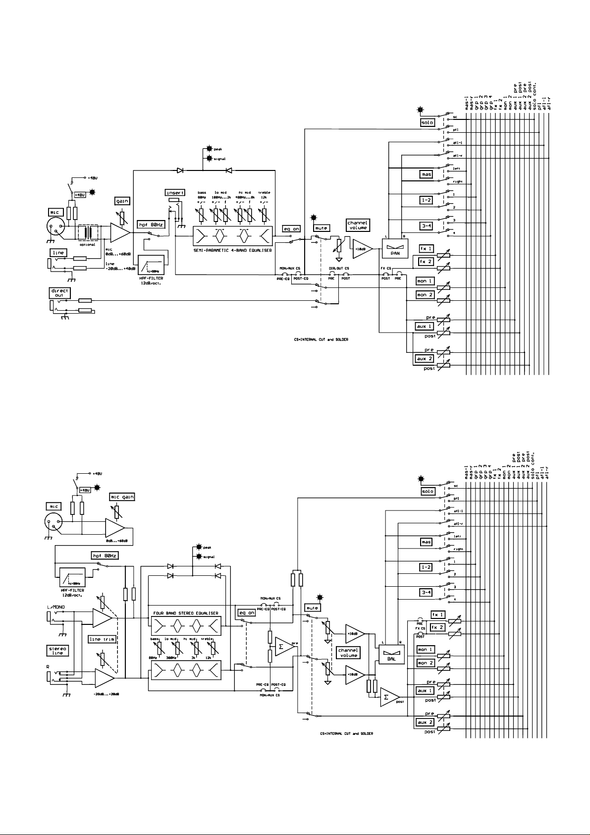
BLOCK DIAGRAMS
Mono Channel
22
Stereo Channel
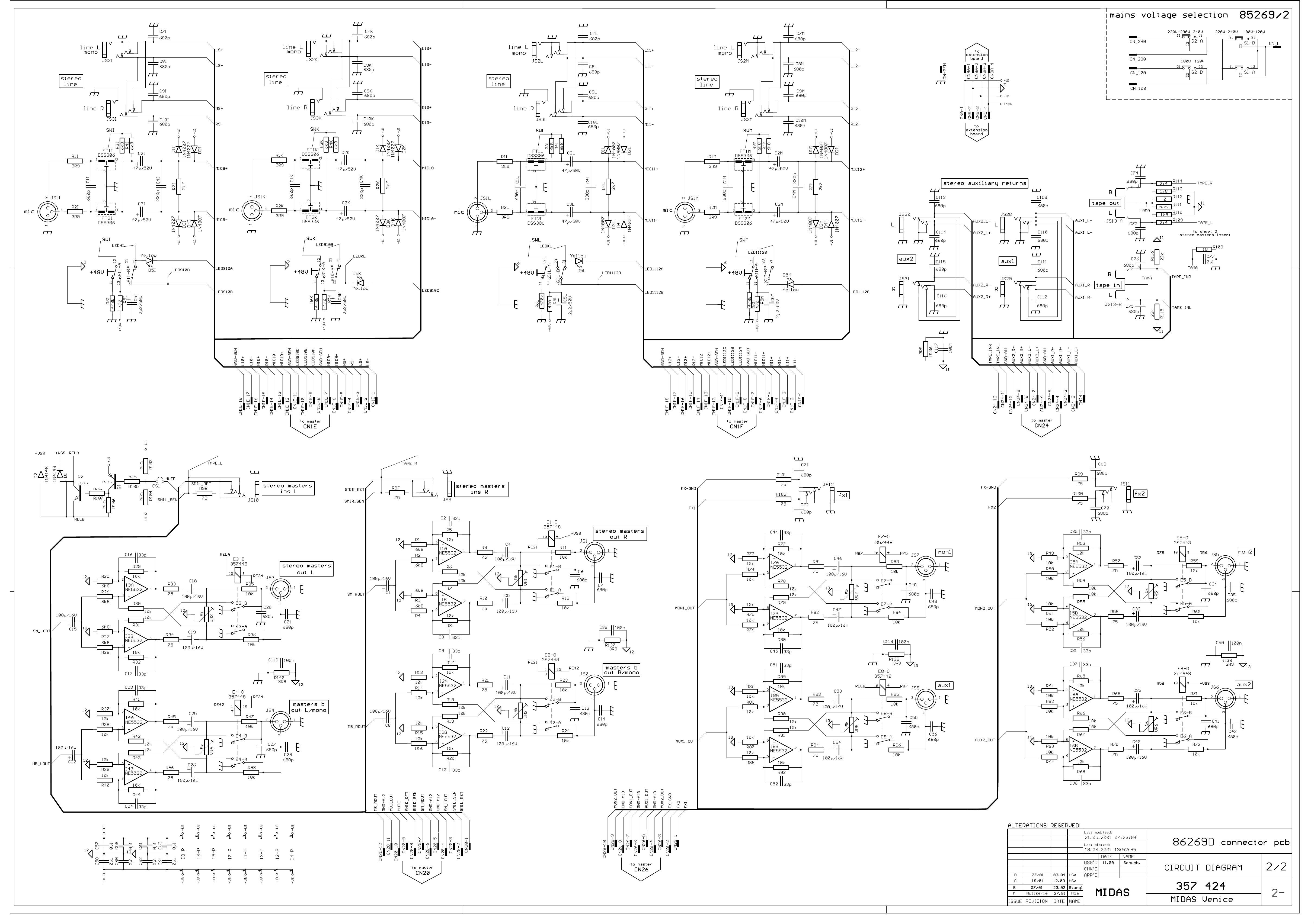
Page 2
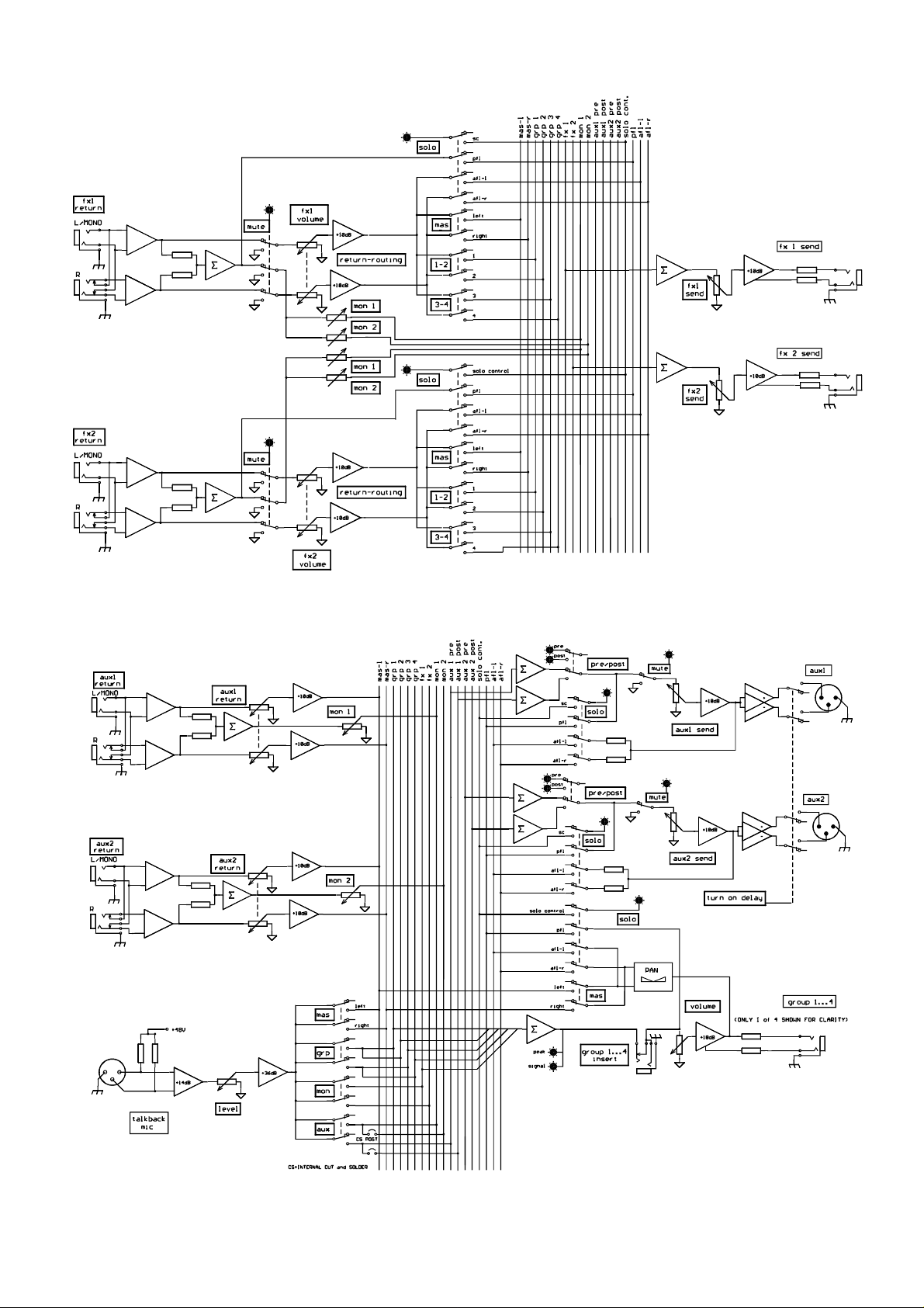
FX-send, FX-return
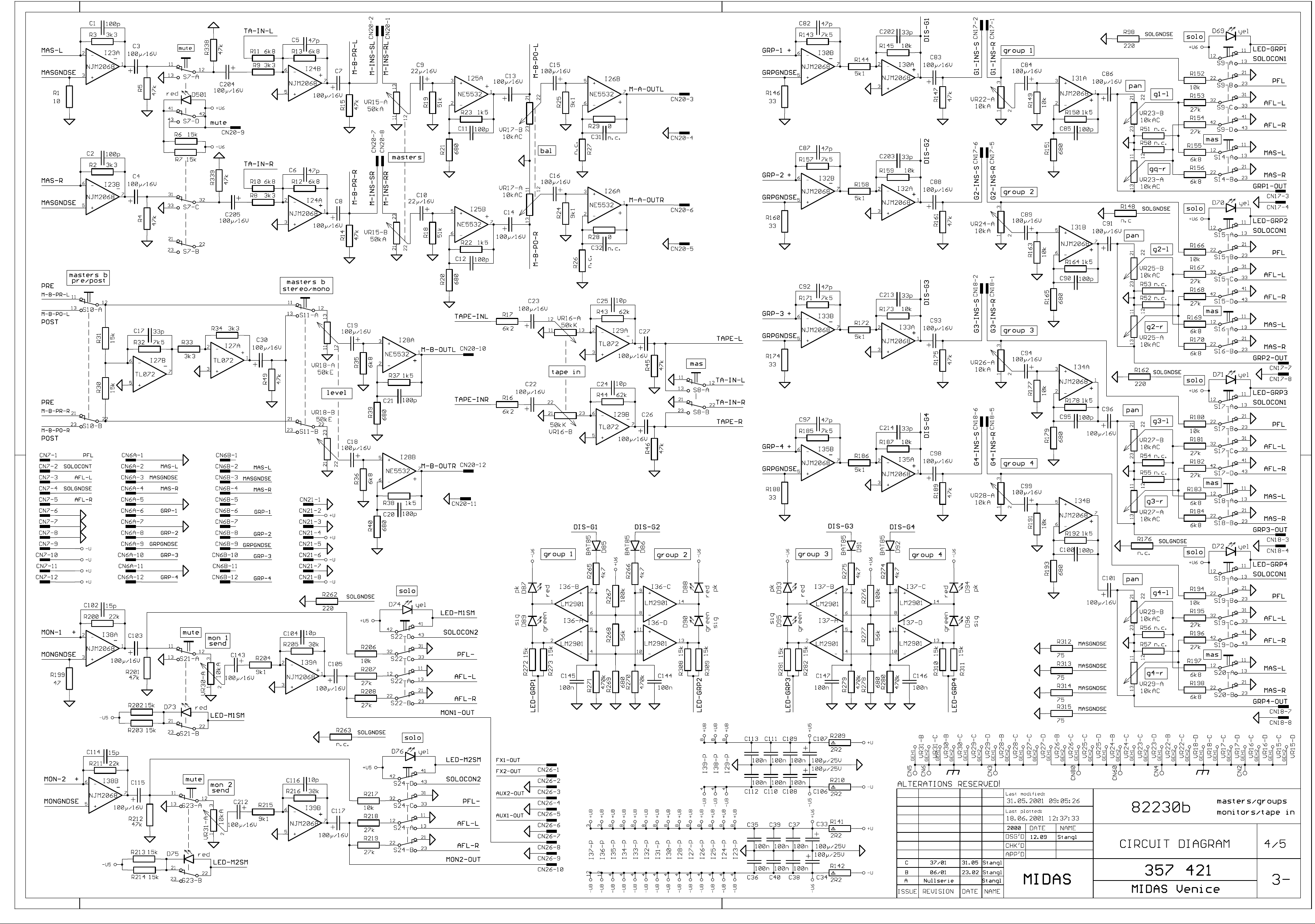
Aux, Groups and Talkback
23
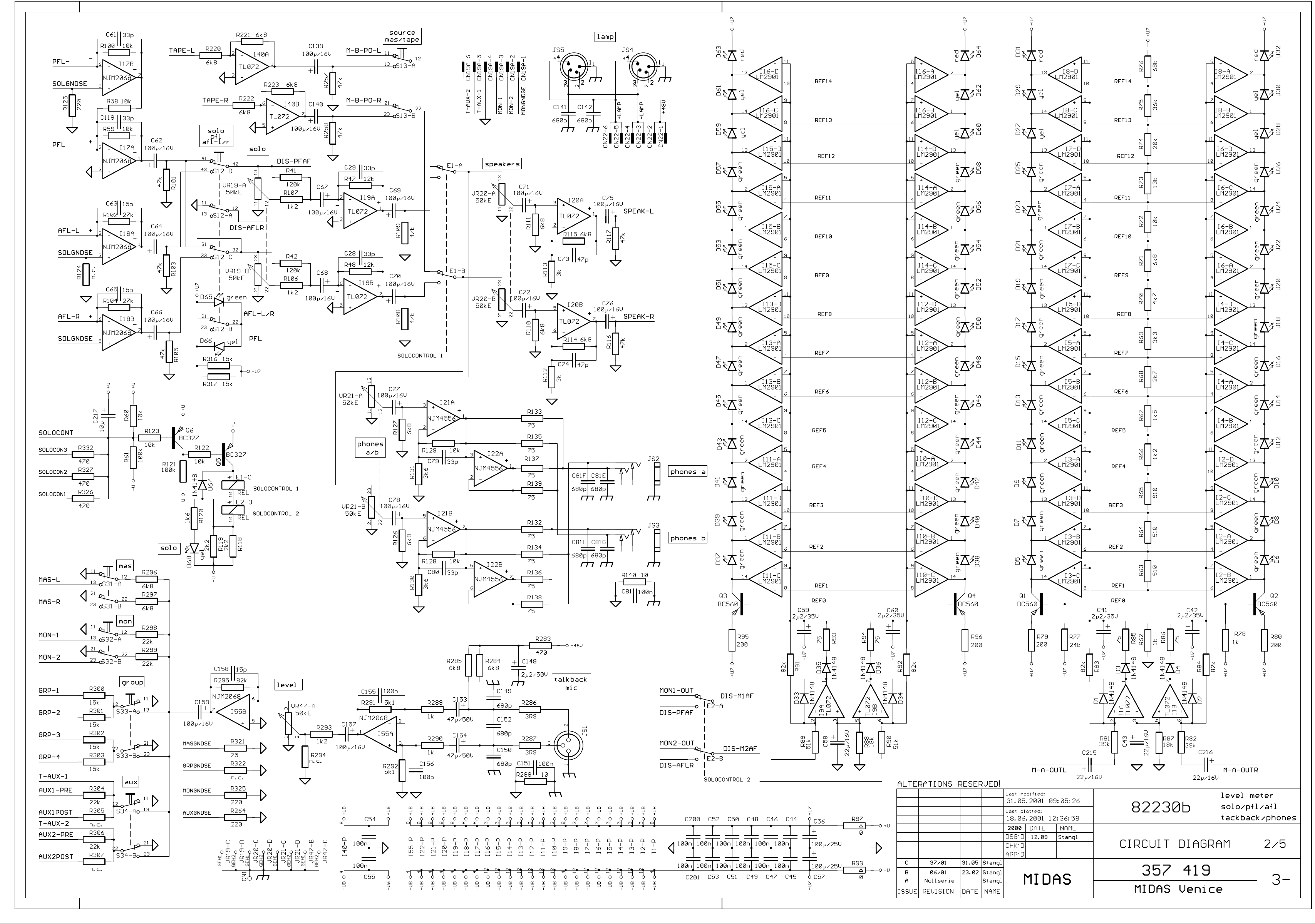
Page 3

Master, Monitor, Tape and Solo
24
Page 4
Page 5
Page 6
Page 7

Page 8
Page 9

Page 10
Page 11

Page 12

MIDAS Venice Pin-Assignments Page 1 / 3
Pin
Assignment
Pin
Assignment
Pin
Assignment
Pin
Assignment
Pin
Assignment
Pin
Assignment
Pin
Assignment
Pin
Assignment
Pin
Assignment
Pin
Assignment
Connection to Connector-PCB
Connection to Master-PCB
Connection to Master-PCB
Mono-Channel-PCB 81346 Stereo- / Master - PCB 82230
CN 1 circuit diagram number CN 6 circuit diagram number CN 7 circuit diagram number CN 1 circuit diagram number CN 6 circuit diagram number CN 7 circuit diagram number
CN1A 357 413 / 2- 375 414 / 2- 357 414 / 2- CN1E 357 417 / 2- CN1A 357 421 / 3- 357 421 / 3CN1B 357 414 / 2- CN1F 357 418 / 2- CN1B 357 421 / 3CN1C 357 415 / 2CN1D 357 416 / 2-
1 L - 1 GND 1 PFL
2 L + 2 Master L 2 Solo Cont
1 LED 12A 1 GND 1 PFL 3 R - 3 Master GND SE 3 AFL-L
2 GND 2 Master L 2 Solo Cont 4 R + 4 Master R 4 Solo GND SE
3 Mic In + 3 Master GND SE 3 AFL-L 5 Mic + 5 GND 5 AFL-R
4 Mic In - 4 Master R 4 Solo GND SE 6 Mic - 6 Grp 1 6 GND
5 GND package 5 GND 5 AFL-R 7 GND package 7 GND 7 GND
6 Ins Send 6 Grp 1 6 GND 8 LED A 8 Grp 2 8 GND
7 Ins Ret 7 GND 7 GND 9 LED B 9 Grp GND SE 9 U 8 Dir-Out 8 Grp 2 8 GND 10 LED C 10 Grp 3 10 U 9 LED 12B 9 Grp GND SE 9 U - 11 GND package 11 GND 11 U +
10 Dir-Out 10 Grp 3 10 U - 12 Mic + 12 Grp 4 12 U +
11 GND package 11 GND 11 U + 13 Mic 12 Ins Ret 12 Grp 4 12 U + 14 R 13 Ins Send 15 R+
14 GND 16 L15 Mic In - 17 L+
16 Mic In + 18 GND package
17 GND
18 LED 12C
Connection to Connector-PCB
Connection to Mono-PCB Connection to Mono-PCB
CN 8 circuit diagram number CN17 circuit diagram number CN18 circuit diagram number
357 418 / 2- 357 421 / 3- 357 421 / 3-
CN 8 circuit diagram number
357 414 / 2-
1 FX 1 1 G1 Ins - Ret 1 G3 Ins Ret
2 FX GND SE 2 G1 Ins - Send 2 G3 Ins Send
1 FX 1 3 FX 2 3 Grp1 Out 3 Grp3 Out
2 FX GND SE 4 Mon 1 4 GND 4 GND
3 FX 2 5 Mon GND SE 5 G2 Ins Ret 5 G4 Ins Ret
4 Mon 1 6 Mon 2 6 G2 Ins Send 6 G4 Ins Send
5 Mon GND SE 7 Aux 1 Pre 7 Grp2 Out 7 Grp4 Out
6 Mon 2 8 Aux 1 Post 8 GND 8 GND
7 Aux 1 Pre 9 Aux GND SE
8 Aux 1 Post 10 Aux 2 Pre
9 Aux GND SE 11 Aux 2 Post
10 Aux 2 Pre 12 not connected
11 Aux 2 Post
12 not connected
Connection to Master-PCB
Connection to Mono-PCB Connection to Connector-PCB Connection to Connector-PCB
Page 13

MIDAS Venice Pin-Assignments Page 2 / 3
Pin
Assignment
Pin
Assignment
Pin
Assignment
Pin
Assignment
Pin
Assignment
CN1A-D
Connection to Mono-PCB
CN1E-F
CN17
CN20
CN24
CN25
Pin
Assignment
Pin
Assignment
Pin
Assignment
1
48V +
1
Aux1 Ret L +
1
Speak L
circuit diagram number
CN1A-D
CN9
Connection to Power Supply-PCB
Connection among Master-PCB
Connection to Connector-PCB
Connector-PCB 86269
Stereo- / Master - PCB 82230
CN 2 circuit diagram number CN 9 circuit diagram number CN19 circuit diagram number CN20 circuit diagram number CN21 circuit diagram number
357 423 / 2- CN 9 357 424 / 2- CN19A 357 419 / 3- 357 421 / 3- 357 421 / 3-
CN9A 357 424 / 2- CN19B 357 420 / 3-
1 48V + LED 1 U1 + 1 Mon GND SE 1 Send Master Insert L Ret 1 GND
2 Relays 2 GND 2 Mon 2 2 Send Master Insert L Send 2 U +
3 48V + 3 U1 - 3 Mon 1 3 Send Master L Out 3 GND
4 48V + 4 48V + 4 GND 4 GND A12 4 U +
5 GND 5 T-Aux 1 5 GND A12 5 GND
6 VSS + 6 T-Aux 2 6 Send Master R Out 6 U 7 16V - 7 Send Master Insert R Send 7 GND
8 16V - 8 Send Master Insert R Ret 8 U 9 16V + 9 Mute
10 16V + 10 MB L Out
11 GND A12
Connection to Power-Supply-PCB
Connection to Extension-PCB 12 MB Rout
Connection to Stereo-PCB
Connection to Master-PCB
CN18 CN22 circuit diagram number CN24 circuit diagram number CN25 circuit diagram number
Connection to Master-PCB
Connection to Master-PCB
Connection to Master-PCB
Connection to Master-PCB
Extension-PCB Nr. 86270
357 426 / 2- 6 Lamp+ 6 Aux2 Ret L + 6 FX1 Ret L +
Connection to Mono-PCB 7 Aux2 Ret L - 7 FX1 Ret L -
357 426 / 2- 9 Aux2 Ret R - 9 FX2 Ret R +
Connection to Connector-PCB 10 GND 10 FX2 Ret R -
Connection to Power Supply-PCB Connection to Connector-PCB
357 419 / 3- 357 420 / 3- 357 420 / 3-
2 48V + 2 Aux1 Ret L - 2 Speak R
3 Lamp - 3 Aux1 Ret R + 3 GND
4 Lamp - 4 Aux1 Ret R - 4 FX1 Ret R +
5 Lamp + 5 GND 5 FX1 Ret R -
8 Aux2 Ret R + 8 GND
11 Tape In L 11 FX2 Ret L +
12 Tape In R 12 FX2 Ret L -
Connection to Connector-PCB
Page 14
MIDAS Venice Pin-Assignments Page 3 / 3
Pin
Assignment
Pin
Assignment
Pin
Assignment
Pin
Assignment
Stereo- / Master - PCB 82230
CN26 circuit diagram number
357 421 / 3-
1 FX1 Out
2 FX2 Out
3 FX GND
4 AUX2 Out
5 GND A13
6 AUX1 Out
7 GND A13
8 Mon 1 Out
9 GND A13
10 Mon 2 Out
Connection to Connector-PCB
Power Supply PCB 85277/1
CN 2 circuit diagram number CN21 circuit diagram number CN22 circuit diagram number
357 412 / 3- 357 412 / 3- 357 412 / 3-
1 48V + LED 1 GND 1 48V +
2 Relays 2 U + 2 48V +
3 48V + 3 GND 3 Lamp -
4 48V + 4 U + 4 Lamp -
5 GND 5 GND 5 Lamp +
6 VSS + 6 U - 6 Lamp+
7 16V - 7 GND
8 16V - 8 U -
9 16V +
10 16V +
Connection to Connector-PCB
Connection to Master-PCB Connection to Master-PCB
Page 15

Page 16

Page 17

Page 18

VENICE 160 1 / 4
Ersatzteilliste - Bill of Materials
173031
VENICE 160 100V
173032
VENICE 160 120V
173033
VENICE 160 220V
173019
VENICE 160 230V
173034
VENICE 160 240V
Pos. Nr.
Best. Nr.
Zubehör
Accessories & packaging material
Mechanische Teile
Cabinet material
Ref. No.
Part No. Bezeichnung Qty Description
359941 BEDIENUNGSANL. VENICE 1 owner's manual VENICE
300425 KABEL-NETZ 2.0 M 10A 1 power cable Europe
346832 KABEL-NETZ UL/CSA 10A/125V 1 power cable US
354619 KABEL-NETZ SAA 10A/250V 1 power cable UK
302583 SICHER T 1.600 A/250V 1 fuse 1.6A slow blow
328391 SICHER-HALTER-KAPPE FEK 1 fuse holder carrier
359992 SCHUTZBEZUG VENICE 160 1 dust cover VENICE 160
360935 RACKWINKEL-SATZ VENICE 160 1 mounting brackets ( pair )
359942 KRT. VENICE 160 1 carton inner VENICE 160
359943 KRT. VENICE 160 AUSSEN 1 carton outer VENICE 160
359944 STYROPOR-EINL. LI. VENICE 1 foam left hand
359945 STYROPOR-EINL. RE. VENICE 1 foam right hand
338158 SCHUTZHÜLLE 800X1200X0,07 1 plastic bag
359877 DK 11,4 GR/WS/DG B 6FL 33 knob rotary l.gr/wh/l.gr
359876 DK 11,4 DG/WS/GR B 6FL 15 knob rotary gr/wh/l.gr
359878 DK 11,4 DG/WS/BL B 6FL 24 knob rotary gr/wh/bl
359879 DK 11,4 GR/WS/BL B 6FL 16 knob rotary l.gr/wh/bl
359990 DK 11,4 DG/WS/DG B 6FL 12 knob rotary gr/wh/gr
359991 DK 11,4 GR/WS/GN B 6FL 26 knob rotary l.gr/wh/gn
358364 DK 11,4 GR/WS/RT B 6FL 30 knob rotary l.gr/wh/rd
359993 DK 11,4 DG/SW/GE B 6FL 28 knob rotary gr/blk/yl
359994 DK 11,4 GR/SW/GE B 6FL 1 knob rotary l.gr/blk/yl
359995 DK 11,4 DG/WS/RT B 6FL 2 knob rotary gr/wh/rd
359946 SK 24X11 GR/SW 4X1,2 12 knob slide l.gr/blk
359947 SK 24X11 BL/SW 4X1,2 4 knob slide bl/blk
359948 SK 24X11 RT/SW 4X1,2 3 knob slide rd/blk
359949 SK 24X11 GN/SW 4X1,2 2 knob slide gn/blk
359645 TK 9,8X9,8 RT 3,3 17 knob switch red square
360000 TK 7,5X6 RT 3,3 14 knob switch red small
359999 TK 9,8X6 RT 3,3 2 knob switch red mid
358363 TK 7,5X6 GR 3,3 63 knob switch l.gr small
358360 TK 9,8X6 GR 3,3 26 knob switch l.gr mid
359863 TK 2,8 SW 3,3 12 knob switch blk +48V
359647 EINLEGEBLENDE VENICE 160 1 logo VENICE 160
335589 FUSS-GUMMI SJ 5009 SW 4 rubber foot
358631 KABEL-KONFEKT 12POL 0.220M 1 ribbon cable assy 12-way
358630 KABEL-KONFEKT 12POL 0.290M 1 ribbon cable assy 12-way
358634 KABEL-KONFEKT-BUS 12POL 3X 1 ribbon cable assy 12-way
358686 KABEL-KONFEKT 8POL 0.860M 1 ribbon cable assy 8-way
Page 19

VENICE 160 2 / 4
Pos. Nr.
Best. Nr.
Printplatten, bestückt
Printed circuit board assemblies
852788
PCBAR#VENICE 160
1
pcb assy 85278 power supply
Ref. No.
CNACx 343516 FL.STECKER 4.8/0.5 1 connector 4.8mm faston
CNGND 343516 FL.STECKER 4.8/0.5 1 connector 4.8mm faston
CNPE2 330269 FL.STECKER 6.3/0.8 1 connector 6.3mm faston
CNPE3 330269 FL.STECKER 6.3/0.8 1 connector 6.3mm faston
CNT01 329022 FL.STECKER 6.3/0.8 1 connector 6.3mm faston
CNT02 329022 FL.STECKER 6.3/0.8 1 connector 6.3mm faston
CN02A 344975 MESSERLST. 10POL 1 connector male 10-pin
CN021 344862 MESSERLST. 8POL 1 connector male 8-pin
CN022 345489 MESSERLST. 6POL 1 connector male 6-pin
C0001 341714 KO-SO 0.10MF 275V 20% K 1 safety cap 100nF/275V
C0002 329021 KO-KER 0.10MF 100V 20% 1 cap ceramic 100nF
C0003 329021 KO-KER 0.10MF 100V 20% 1 cap ceramic 100nF
C0008 335935 KO-EL 2200.000MF 35V 1 cap electrolytic 2200uF/35V
C0009 335935 KO-EL 2200.000MF 35V 1 cap electrolytic 2200uF/35V
C0010 335935 KO-EL 2200.000MF 35V 1 cap electrolytic 2200uF/35V
C0011 335935 KO-EL 2200.000MF 35V 1 cap electrolytic 2200uF/35V
C0012 329021 KO-KER 0.10MF 100V 20% 1 cap ceramic 100nF
C0013 329021 KO-KER 0.10MF 100V 20% 1 cap ceramic 100nF
C0014 327815 KO-EL 22.000MF 25V 1 cap electrolytic 22uF/25V
C0015 327815 KO-EL 22.000MF 25V 1 cap electrolytic 22uF/25V
C0016 329021 KO-KER 0.10MF 100V 20% 1 cap ceramic 100nF
C0017 341920 KO-EL 470.000MF 63V 1 cap electrolytic 470uF/63V
C0018 301478 KO-EL 22.000MF 63V 1 cap electrolytic 22uF/63V
C0019 301491 KO-EL 100.000MF 50V 1 cap electrolytic 100uF/50V
C0020 329021 KO-KER 0.10MF 100V 20% 1 cap ceramic 100nF
C0021 335935 KO-EL 2200.000MF 35V 1 cap electrolytic 2200uF/35V
C0022 342923 KO-FOL 0.220MF 63V 5% 1 cap mylar 220nF
C0023 307445 KO-EL 10.000MF 35V 1 cap electrolytic 10uF/35V
C0024 329021 KO-KER 0.10MF 100V 20% 1 cap ceramic 100nF
C0025 343530 KO-EL 47.000MF 50V 1 cap electrolytic 47uF/50V
C0026 343530 KO-EL 47.000MF 50V 1 cap electrolytic 47uF/50V
C0028 327815 KO-EL 22.000MF 25V 1 cap electrolytic 22uF/25V
C0029 301491 KO-EL 100.000MF 50V 1 cap electrolytic 100uF/50V
C0030 341920 KO-EL 470.000MF 63V 1 cap electrolytic 470uF/63V
C0032 329021 KO-KER 0.10MF 100V 20% 1 cap ceramic 100nF
Part No. Bezeichnung Qty Description
358687 KABEL-KONFEKT 8POL 1.000M 2 ribbon cable assy 8-way
358690 KABEL-KONFEKT 12POL 0.720M 1 ribbon cable assy 12-way
360944 KABEL-KONFEKT 12POL 0.660M 1 ribbon cable assy 12-way
360943 KABEL-KONFEKT 12POL 0.560M 1 ribbon cable assy 12-way
360941 KABEL-KONFEKT 6POL 0.500M 1 ribbon cable assy 6-way
349610 KABEL-KONFEKT 10POL 0.520M 2 ribbon cable assy 10-way
341984 KABEL-KONFEKT 4POL 0.150M 1 ribbon cable assy 4-way
348565 KABEL-KONFEKT 18POL 0.200M 6 ribbon cable assy 18way
358390 SEITENTEIL LINKS VENICE 1 side wing left hand
358534 SEITENTEIL RECHTS VENICE 1 side wing rihgt hand
360221 FRONTLEISTE VENICE 160 1 arm rest VENICE 160
358391 FRONTBL-BED VENICE 160 1 front panel VENICE 160
358392 RÜCKWAND-BED VENICE 160 1 rear panel VENICE 160
358691 RKT VENICE 100-240V 1 mains transformer VENICE
Page 20

VENICE 160 3 / 4
Pos. Nr.
Best. Nr.
813468
PCBAR#VENICE 160/240/320 R1
1
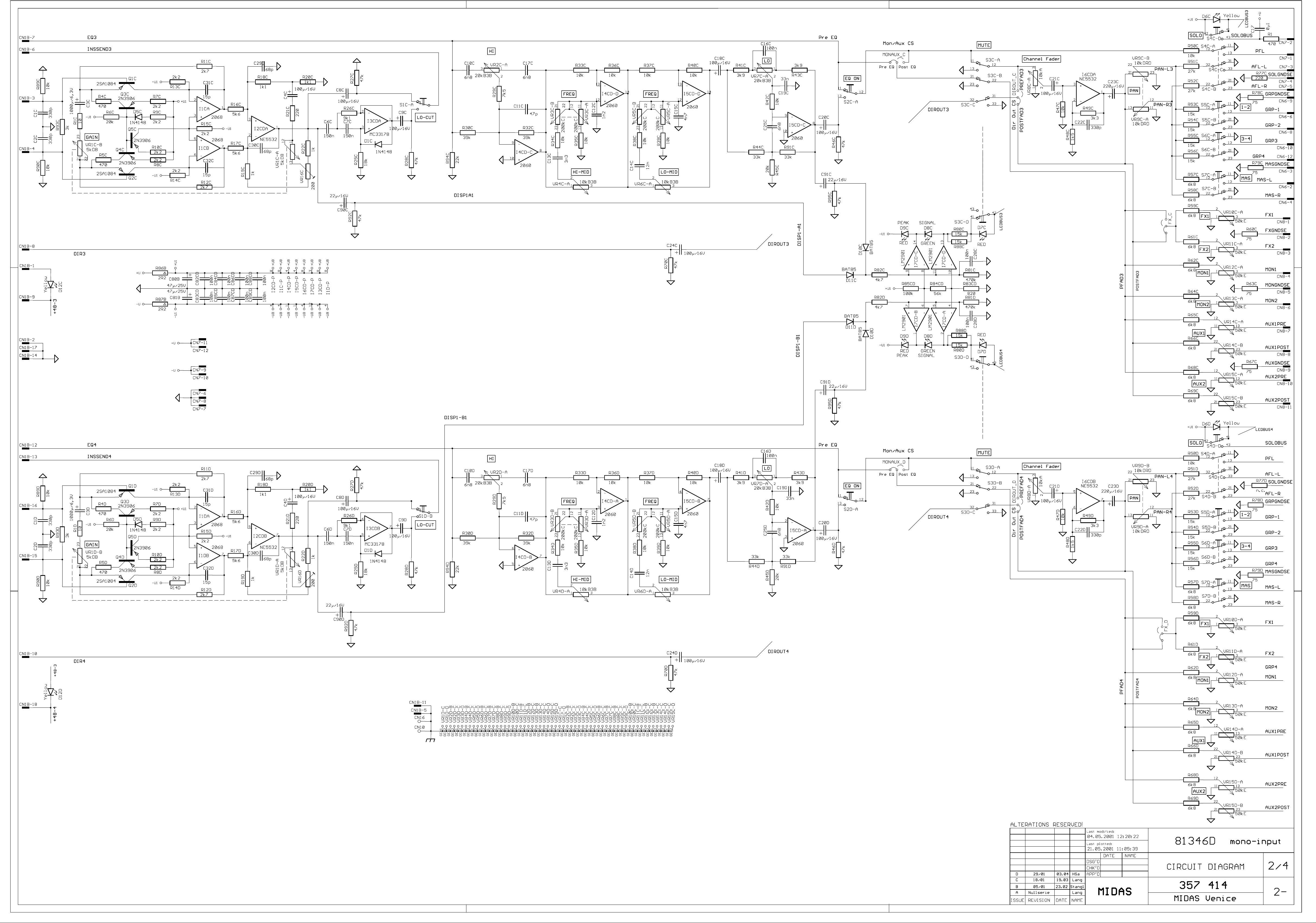
pcb assy 81346 input mono
822308
PCBAR#VENICE 160/240/320
1
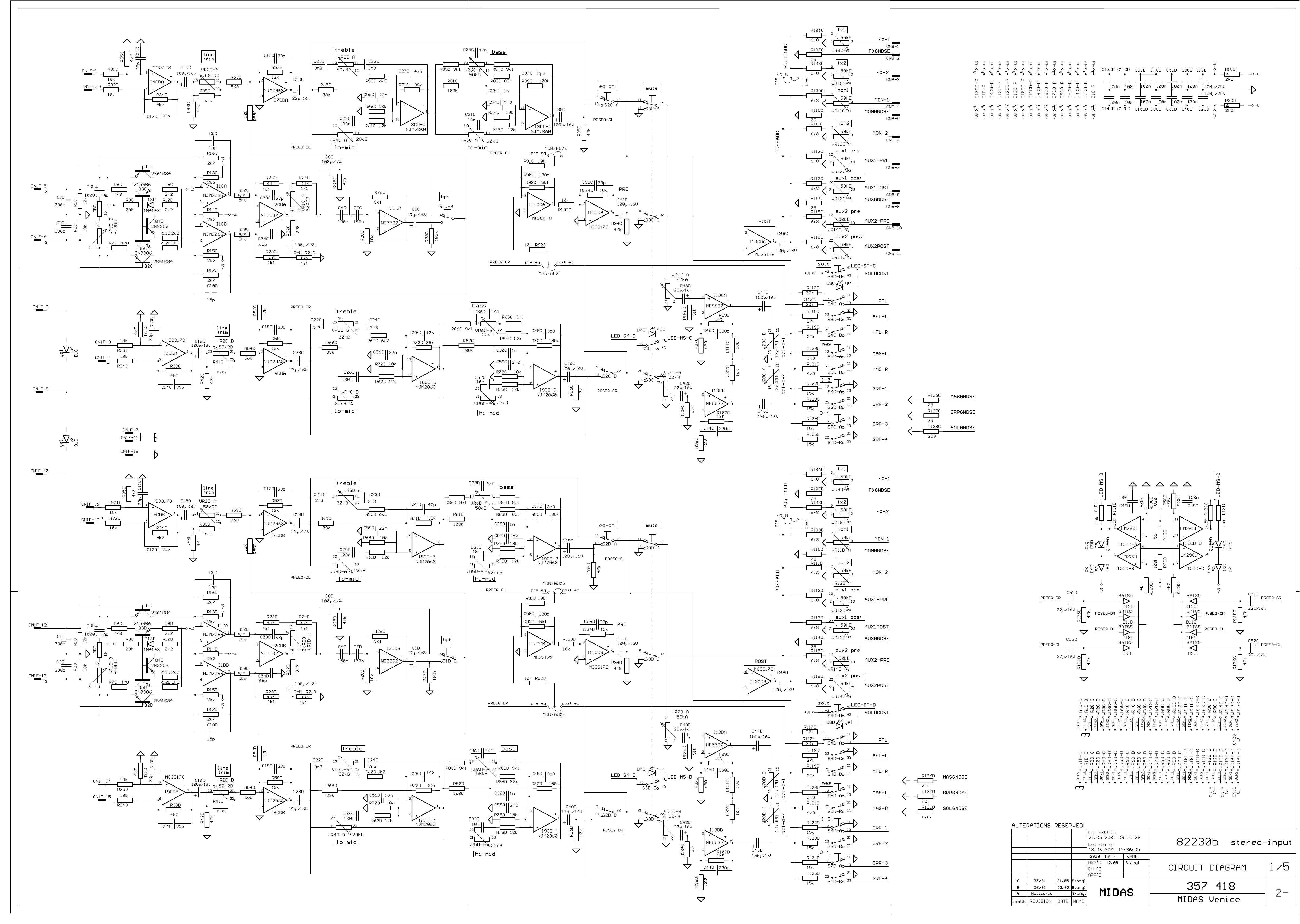
pcb assy 82230 input stereo
862698
PCBAR#VENICE 160/240/320
1
pcb assy 86269 connectors
Ref. No.
C0033 329021 KO-KER 0.10MF 100V 20% 1 cap ceramic 100nF
D0005 301254 DIODE 1N 4148 AXIAL 1 diode 1N 4148
D0006 301254 DIODE 1N 4148 AXIAL 1 diode 1N 4148
D0007 304360 DIODE 1N 4007 GEGURTET 1 diode 1N 4002
D0008 304360 DIODE 1N 4007 GEGURTET 1 diode 1N 4002
D0009 304360 DIODE 1N 4007 GEGURTET 1 diode 1N 4002
D001A 304364 DIODZ ZPY 30V 1.30W 1 diode zener 30V
D0010 304360 DIODE 1N 4007 GEGURTET 1 diode 1N 4002
D0011 304360 DIODE 1N 4007 GEGURTET 1 diode 1N 4002
D0012 304360 DIODE 1N 4007 GEGURTET 1 diode 1N 4002
D0013 304360 DIODE 1N 4007 GEGURTET 1 diode 1N 4002
D0014 304360 DIODE 1N 4007 GEGURTET 1 diode 1N 4002
D0015 304360 DIODE 1N 4007 GEGURTET 1 diode 1N 4002
D0016 304360 DIODE 1N 4007 GEGURTET 1 diode 1N 4002
D0017 358946 DIODE 1N 5401 BEARB.AUS 1 diode 1N 5401
D0018 358946 DIODE 1N 5401 BEARB.AUS 1 diode 1N 5401
D0019 358946 DIODE 1N 5401 BEARB.AUS 1 diode 1N 5401
D0020 358946 DIODE 1N 5401 BEARB.AUS 1 diode 1N 5401
D0022 301254 DIODE 1N 4148 AXIAL 1 diode 1N 4148
D0025 304360 DIODE 1N 4007 GEGURTET 1 diode 1N 4002
D0026 304360 DIODE 1N 4007 GEGURTET 1 diode 1N 4002
F0002 302587 SICHER T 3.150 A/250V 1 fuse 3.15A slow blow
F0003 302587 SICHER T 3.150 A/250V 1 fuse 3.15A slow blow
F0004 302582 SICHER T 1.000 A/250V 1 fuse 1A slow blow
F0005 305205 SICHER T 2.500 A/250V 1 fuse 2.5A slow blow
G0001 357140 GLRI GBU 8K 1 rectifier
I0001 354199 IC SPNG.REGL. LM 317 T 1 IC LM 317 voltage regulator
I0002 354929 IC SPNG.REGL. LM 337 T 1 IC LM 337 voltage regulator
I0003 354199 IC SPNG.REGL. LM 317 T 1 IC LM 317 voltage regulator
I0004 354199 IC SPNG.REGL. LM 317 T 1 IC LM 317 voltage regulator
JS001 338835 STECKER-KALTGERÄTE 1 connector male mains
00010 301233 TRANS BD 246 B 0 transistor BD 246 B
00010 301234 TRANS BD 245 B 0 transistor BD 245 B
Q0003 348423 TRANS MPSA 92 1 transistor MPSA 92
Q0004 306928 TRANS BC 560 C 1 transistor BC 560 C
Q0005 306928 TRANS BC 560 C 1 transistor BC 560 C
Q0006 306928 TRANS BC 560 C 1 transistor BC 560 C
Q0007 306928 TRANS BC 560 C 1 transistor BC 560 C
Q0008 348591 TRANS BC 618 DARL. TO 92 1 transistor BC 618
Q0009 307150 TRANS BC 337-25 TO 92 1 transistor BC 337-25
S0001 354927 SCHALTER-NETZ 1 switch mains
00005 303576 SICHER-HALTE-FEDER 8 fuse clip
00010 328390 SICHER-HALTER FAU 1 fuse holder
Part No. Bezeichnung Qty Description
please refer to bom of VENICE 240
please refer to bom of VENICE 240
Page 21

VENICE 160 4 / 4
Pos. Nr.
Best. Nr.
Ref. No.
Part No. Bezeichnung Qty Description
please refer to bom of VENICE 240
Page 22

VENICE 240 Page 1 / 22
Ersatzteilliste - Bill of Materials
173042
VENICE 240 120V
173044
VENICE 240 240V
173020
VENICE 240 230V
Pos. Nr.
Best. Nr.
Zubehör
Accessories & packaging material
Mechanische Teile
Cabinet material
Ref. No.
Part No. Bezeichnung Qty Description
359941 BEDIENUNGSANL. VENICE 1 owner's manual VENICE
346832 KABEL-NETZ UL/CSA 10A/125V 1 power cable US
354619 KABEL-NETZ SAA 10A/250V 1 power cable UK
300425 KABEL-NETZ 2.0 M 10A 1 power cable Europe
302587 SICHER T 3.150 A/250V 1 fuse 3.15A slow blow
302583 SICHER T 1.600 A/250V 1 fuse 1.6A slow blow / US only !!
328391 SICHER-HALTER-KAPPE FEK 1 fuse holder carrier
360003 SCHUTZBEZUG VENICE 240 1 dust cover VENICE 240
360005 KRT. VENICE 240 1 carton inner V240
360006 KRT. VENICE 240 AUSSEN 1 carton outer V240
359944 STYROPOR-EINL. LI. VENICE 1 foam left hand
359945 STYROPOR-EINL. RE. VENICE 1 foam right hand
338158 SCHUTZHÜLLE 800X1200X0,07 1 plastic bag
341592 STECKER-FL. XLR 6POL 1 connector XLR male 6-pin
359877 DK 11,4 GR/WS/DG B 6FL 49 knob rotary l.gr/wh/l.gr
359876 DK 11,4 DG/WS/GR B 6FL 23 knob rotary gr/wh/l.gr
359878 DK 11,4 DG/WS/BL B 6FL 40 knob rotary gr/wh/bl
359879 DK 11,4 GR/WS/BL B 6FL 32 knob rotary l.gr/wh/bl
359990 DK 11,4 DG/WS/DG B 6FL 20 knob rotary gr/wh/gr
359991 DK 11,4 GR/WS/GN B 6FL 42 knob rotary l.gr/wh/gn
358364 DK 11,4 GR/WS/RT B 6FL 46 knob rotary l.gr/wh/rd
359993 DK 11,4 DG/SW/GE B 6FL 44 knob rotary gr/blk/yl
359994 DK 11,4 GR/SW/GE B 6FL 1 knob rotary l.gr/blk/yl
359995 DK 11,4 DG/WS/RT B 6FL 2 knob rotary gr/wh/rd
359946 SK 24X11 GR/SW 4X1,2 20 knob slide l.gr/blk
359947 SK 24X11 BL/SW 4X1,2 4 knob slide bl/blk
359948 SK 24X11 RT/SW 4X1,2 3 knob slide rd/blk
359949 SK 24X11 GN/SW 4X1,2 2 knob slide gn/blk
359645 TK 9,8X9,8 RT 3,3 25 knob switch red square
360000 TK 7,5X6 RT 3,3 22 knob switch red small
359999 TK 9,8X6 RT 3,3 2 knob switch red mid
358363 TK 7,5X6 GR 3,3 95 knob switch l.gr small
358360 TK 9,8X6 GR 3,3 34 knob switch l.gr mid
359863 TK 2,8 SW 3,3 20 knob switch blk +48V
359648 EINLEGEBLENDE VENICE 240 1 logo VENICE 240
335589 FUSS-GUMMI SJ 5009 SW 5 rubber foot
358632 KABEL-KONFEKT-BUS 12POL 3X 1 ribbon cable 12-way 3conn
358633 KABEL-KONFEKT-BUS 12POL 3X 1 ribbon cable 12-way 3conn
358635 KABEL-KONFEKT-BUS 12POL 4X 1 ribbon cable 12-way 4conn
358686 KABEL-KONFEKT 8POL 0.930M 1 ribbon cable assy 8-way
358687 KABEL-KONFEKT 8POL 1.120M 2 ribbon cable assy 8-way
Page 23

VENICE 240 Page 2 / 22
Pos. Nr.
Best. Nr.
Printplatten, bestückt
Printed circuit board assemblies
852778
PCBAR#VENICE 240/320
1
pcb assy 85277 power supply
Ref. No.
CNACx 343516 FL.STECKER 4.8/0.5 1 connector 4.8mm faston
CNGND 343516 FL.STECKER 4.8/0.5 1 connector 4.8mm faston
CNPE2 330269 FL.STECKER 6.3/0.8 1 connector 6.3mm faston
CNPE3 330269 FL.STECKER 6.3/0.8 1 connector 6.3mm faston
CNT01 329022 FL.STECKER 6.3/0.8 1 connector 6.3mm faston
CNT02 329022 FL.STECKER 6.3/0.8 1 connector 6.3mm faston
CN00x 343516 FL.STECKER 4.8/0.5 1 connector 4.8mm faston
CN02A 344975 MESSERLST. 10POL 1 connector male 10-pin
CN021 344862 MESSERLST. 8POL 1 connector male 8-pin
CN022 345489 MESSERLST. 6POL 1 connector male 6-pin
C0001 341714 KO-SO 0.10MF 275V 20% K 1 safety cap 100nF/275V
C0002 329021 KO-KER 0.10MF 100V 20% 1 cap ceramic 100nF
C0003 329021 KO-KER 0.10MF 100V 20% 1 cap ceramic 100nF
C0004 335935 KO-EL 2200.000MF 35V 1 cap electrolytic 2200uF/35V
C0005 335935 KO-EL 2200.000MF 35V 1 cap electrolytic 2200uF/35V
C0008 335935 KO-EL 2200.000MF 35V 1 cap electrolytic 2200uF/35V
C0009 335935 KO-EL 2200.000MF 35V 1 cap electrolytic 2200uF/35V
C0010 335935 KO-EL 2200.000MF 35V 1 cap electrolytic 2200uF/35V
C0011 335935 KO-EL 2200.000MF 35V 1 cap electrolytic 2200uF/35V
C0012 329021 KO-KER 0.10MF 100V 20% 1 cap ceramic 100nF
C0013 329021 KO-KER 0.10MF 100V 20% 1 cap ceramic 100nF
C0014 327815 KO-EL 22.000MF 25V 1 cap electrolytic 22uF/25V
C0015 327815 KO-EL 22.000MF 25V 1 cap electrolytic 22uF/25V
C0016 329021 KO-KER 0.10MF 100V 20% 1 cap ceramic 100nF
C0017 341920 KO-EL 470.000MF 63V 1 cap electrolytic 470uF/63V
C0018 301478 KO-EL 22.000MF 63V 1 cap electrolytic 22uF/63V
C0019 301491 KO-EL 100.000MF 50V 1 cap electrolytic 100uF/50V
C0020 329021 KO-KER 0.10MF 100V 20% 1 cap ceramic 100nF
C0021 335935 KO-EL 2200.000MF 35V 1 cap electrolytic 2200uF/35V
C0022 342923 KO-FOL 0.220MF 63V 5% 1 cap mylar 220nF
C0023 307445 KO-EL 10.000MF 35V 1 cap electrolytic 10uF/35V
C0024 329021 KO-KER 0.10MF 100V 20% 1 cap ceramic 100nF
C0025 343530 KO-EL 47.000MF 50V 1 cap electrolytic 47uF/50V
C0026 343530 KO-EL 47.000MF 50V 1 cap electrolytic 47uF/50V
C0027 335935 KO-EL 2200.000MF 35V 1 cap electrolytic 2200uF/35V
C0028 327815 KO-EL 22.000MF 25V 1 cap electrolytic 22uF/25V
Part No. Bezeichnung Qty Description
358688 KABEL-KONFEKT 12POL 0.900M 1 ribbon cable assy 12-way
358689 KABEL-KONFEKT 12POL 0.800M 1 ribbon cable assy 12-way
358690 KABEL-KONFEKT 12POL 0.720M 1 ribbon cable assy 12-way
354302 KABEL-KONFEKT 6POL 0.600M 1 ribbon cable 6-way
348388 KABEL-KONFEKT 10POL 0.620M 2 ribbon cable assy 10-way
341984 KABEL-KONFEKT 4POL 0.150M 1 ribbon cable assy 4-way
353397 KABEL-KONFEKT 18POL 0.110M 10 ribbon cable assy 18-way
358390 SEITENTEIL LINKS VENICE 1 side wing left hand
358534 SEITENTEIL RECHTS VENICE 1 side wing rihgt hand
359769 FRONTLEISTE VENICE 240 1 armrest VENICE 240
359631 FRONTBL-BED VENICE 240 1 front panel VENICE 240
359632 RÜCKWAND-BED VENICE 240 1 rear panel VENICE 240
358691 RKT VENICE 100-240V 1 mains transformer VENICE
Page 24

VENICE 240 Page 3 / 22
Pos. Nr.
Best. Nr.
Ref. No.
C0029 301491 KO-EL 100.000MF 50V 1 cap electrolytic 100uF/50V
C0030 341920 KO-EL 470.000MF 63V 1 cap electrolytic 470uF/63V
C0031 341920 KO-EL 470.000MF 63V 1 cap electrolytic 470uF/63V
C0032 329021 KO-KER 0.10MF 100V 20% 1 cap ceramic 100nF
C0033 329021 KO-KER 0.10MF 100V 20% 1 cap ceramic 100nF
D0005 301254 DIODE 1N 4148 AXIAL 1 diode 1N 4148
D0006 301254 DIODE 1N 4148 AXIAL 1 diode 1N 4148
D0007 304360 DIODE 1N 4007 GEGURTET 1 diode 1N 4002
D0008 304360 DIODE 1N 4007 GEGURTET 1 diode 1N 4002
D0009 304360 DIODE 1N 4007 GEGURTET 1 diode 1N 4002
D001A 304364 DIODZ ZPY 30V 1.30W 1 diode zener 30V
D0010 304360 DIODE 1N 4007 GEGURTET 1 diode 1N 4002
D0011 304360 DIODE 1N 4007 GEGURTET 1 diode 1N 4002
D0012 304360 DIODE 1N 4007 GEGURTET 1 diode 1N 4002
D0013 304360 DIODE 1N 4007 GEGURTET 1 diode 1N 4002
D0014 304360 DIODE 1N 4007 GEGURTET 1 diode 1N 4002
D0015 304360 DIODE 1N 4007 GEGURTET 1 diode 1N 4002
D0016 304360 DIODE 1N 4007 GEGURTET 1 diode 1N 4002
D0017 358946 DIODE 1N 5401 BEARB.AUS 1 diode 1N 5401
D0018 358946 DIODE 1N 5401 BEARB.AUS 1 diode 1N 5401
D0019 358946 DIODE 1N 5401 BEARB.AUS 1 diode 1N 5401
D0020 358946 DIODE 1N 5401 BEARB.AUS 1 diode 1N 5401
D0021 301254 DIODE 1N 4148 AXIAL 1 diode 1N 4148
D0022 301254 DIODE 1N 4148 AXIAL 1 diode 1N 4148
D0023 304360 DIODE 1N 4007 GEGURTET 1 diode 1N 4002
D0025 304360 DIODE 1N 4007 GEGURTET 1 diode 1N 4002
D0026 304360 DIODE 1N 4007 GEGURTET 1 diode 1N 4002
E0001 356656 RELAIS 845-N-2C-S-24VDC 1 relay 24V
E0002 356656 RELAIS 845-N-2C-S-24VDC 1 relay 24V
E0003 356745 RELAIS M4-24H 1 relay 24V
F0002 302587 SICHER T 3.150 A/250V 1 fuse 3.15A slow blow
F0003 302587 SICHER T 3.150 A/250V 1 fuse 3.15A slow blow
F0004 302582 SICHER T 1.000 A/250V 1 fuse 1A slow blow
F0005 305205 SICHER T 2.500 A/250V 1 fuse 2.5A slow blow
G0001 357140 GLRI GBU 8K 1 rectifier
I0001 354199 IC SPNG.REGL. LM 317 T 1 IC LM 317 voltage regulator
I0002 354929 IC SPNG.REGL. LM 337 T 1 IC LM 337 voltage regulator
I0003 354199 IC SPNG.REGL. LM 317 T 1 IC LM 317 voltage regulator
I0004 354199 IC SPNG.REGL. LM 317 T 1 IC LM 317 voltage regulator
JS001 338835 STECKER-KALTGERÄTE 1 connector male mains
00010 301233 TRANS BD 246 B 0 transistor BD 246 B
00010 301234 TRANS BD 245 B 0 transistor BD 245 B
Q0003 348423 TRANS MPSA 92 1 transistor MPSA 92
Q0004 306928 TRANS BC 560 C 1 transistor BC 560 C
Q0005 306928 TRANS BC 560 C 1 transistor BC 560 C
Q0006 306928 TRANS BC 560 C 1 transistor BC 560 C
Q0007 306928 TRANS BC 560 C 1 transistor BC 560 C
Q0008 348591 TRANS BC 618 DARL. TO 92 1 transistor BC 618
Q0009 307150 TRANS BC 337-25 TO 92 1 transistor BC 337-25
S0001 354927 SCHALTER-NETZ 1 switch mains
00005 303576 SICHER-HALTE-FEDER 8 fuse clip
00010 328390 SICHER-HALTER FAU 1 fuse holder
Part No. Bezeichnung Qty Description
Page 25

VENICE 240 Page 4 / 22
Pos. Nr.
Best. Nr.
813468
PCBAR#VENICE 160/240/320
2
pcb assy 81346 input mono
Ref. No.
CN006 348802 MESSERLST. 12POL 1 connector male 12-pin
CN007 348802 MESSERLST. 12POL 1 connector male 12-pin
CN008 348802 MESSERLST. 12POL 1 connector male 12-pin
CN01y 346759 MESSERLST. 18POL 1 connector male 18-pin
C001A 357452 KO-KER 330.0PF 100V 10% 1 cap ceramic 330pF
C0017 329021 KO-KER 0.10MF 100V 20% 1 cap ceramic 100nF
C002A 357452 KO-KER 330.0PF 100V 10% 1 cap ceramic 330pF
C003A 357453 KO-EL 1000.000MF 6.3V 1 cap elctrolytic 1000uF/6.3V
C004A 340524 KO-EL 100.000MF 16V 1 cap electrolytic 100uF/16V
C006A 342936 KO-FOL 0.150MF 63V 5% 1 cap mylar 150nF
C007A 342936 KO-FOL 0.150MF 63V 5% 1 cap mylar 150nF
C008A 340524 KO-EL 100.000MF 16V 1 cap electrolytic 100uF/16V
C009A 340524 KO-EL 100.000MF 16V 1 cap electrolytic 100uF/16V
C010A 336094 KO-FOL 6800.000PF 100V 5% 1 cap mylar 6800pF
C011A 301524 KO-KER 47.0PF 500V 10% 1 cap ceramic 47pF
C012A 300302 KO-FOL 1200.000PF 100V 5% 1 cap mylar 1200pF
C013A 326923 KO-FOL 3300.000PF 63V 5% 1 cap mylar 3300pF
C014A 341276 KO-FOL 0.012MF 100V 5% 1 cap mylar 12nF
C015A 327393 KO-FOL 4700.000PF 63V 5% 1 cap mylar 4700pF
C016A 336095 KO-FOL 0.100MF 63V 5% 1 cap mylar 100nF
C017A 336094 KO-FOL 6800.000PF 100V 5% 1 cap mylar 6800pF
C018A 340524 KO-EL 100.000MF 16V 1 cap electrolytic 100uF/16V
C019A 342934 KO-FOL 0.033MF 100V 5% 1 cap mylar 33nF
C020A 340524 KO-EL 100.000MF 16V 1 cap electrolytic 100uF/16V
C021A 340524 KO-EL 100.000MF 16V 1 cap electrolytic 100uF/16V
C022A 301543 KO-KER 330.0PF 500V 10% 1 cap ceramic 330pF
C023A 358639 KO-EL 220.000MF 16V 1 cap electrolytic 220uF/16V
C024A 340524 KO-EL 100.000MF 16V 1 cap electrolytic 100uF/16V
C025A 336094 KO-FOL 6800.000PF 100V 5% 1 cap mylar 6800pF
C028A 329021 KO-KER 0.10MF 100V 20% 1 cap ceramic 100nF
C029A 357451 KO-KER 68.0PF 100V 2% 1 cap ceramic 68pF
C030A 357451 KO-KER 68.0PF 100V 2% 1 cap ceramic 68pF
C031A 335787 KO-KER 15.0PF 100V 2% 1 cap ceramic 15pF
C032A 335787 KO-KER 15.0PF 100V 2% 1 cap ceramic 15pF
C080A 343532 KO-EL 100.000MF 25V 1 cap electrolytic 100uF/25V
C081A 343532 KO-EL 100.000MF 25V 1 cap electrolytic 100uF/25V
C090A 340523 KO-EL 22.000MF 16V 1 cap electrolytic 22uF/16V
C091A 340523 KO-EL 22.000MF 16V 1 cap electrolytic 22uF/16V
C82AB 329021 KO-KER 0.10MF 100V 20% 1 cap ceramic 100nF
C83AB 329021 KO-KER 0.10MF 100V 20% 1 cap ceramic 100nF
C84AB 329021 KO-KER 0.10MF 100V 20% 1 cap ceramic 100nF
C85AB 329021 KO-KER 0.10MF 100V 20% 1 cap ceramic 100nF
C86AB 329021 KO-KER 0.10MF 100V 20% 1 cap ceramic 100nF
C87AB 329021 KO-KER 0.10MF 100V 20% 1 cap ceramic 100nF
C88AB 329021 KO-KER 0.10MF 100V 20% 1 cap ceramic 100nF
C89AB 329021 KO-KER 0.10MF 100V 20% 1 cap ceramic 100nF
D001A 301254 DIODE 1N 4148 AXIAL 1 diode 1N 4148
D005A 301254 DIODE 1N 4148 AXIAL 1 diode 1N 4148
D006A 354005 LED GE 3MM LOW CURRENT 1 led yellow
D007A 354003 LED RT 3MM LOW CURRENT 1 led red
D008A 354004 LED GN 3MM LOW CURRENT 1 led green
Part No. Bezeichnung Qty Description
Page 26

VENICE 240 Page 5 / 22
Pos. Nr.
Best. Nr.
822308
PCBAR#VENICE 160/240/320
1
pcb assy 82230 input stereo
Ref. No.
D009A 354003 LED RT 3MM LOW CURRENT 1 led red
D010A 301297 DIODE BAT 85 SCHOTTKY 1 diode BAT 85
D011A 301297 DIODE BAT 85 SCHOTTKY 1 diode BAT 85
D012A 354005 LED GE 3MM LOW CURRENT 1 led yellow
I001A 354933 IC NJM 2068 D DUAL IN 1 IC NJM 2068
I02AB 327197 IC NE 5532 P 2FACH OP 1 IC NE 5532 N
I03AB 358898 IC MC 33178 2FACH OP 1 IC MC 33178
I04AB 358661 IC NJM 2060 D 1 IC NJM 2060
I05AB 358661 IC NJM 2060 D 1 IC NJM 2060
I06AB 327197 IC NE 5532 P 2FACH OP 1 IC NE 5532 N
I07AB 343502 IC LM 2901 N 1 IC LM 2901
Q001A 343536 TRANS 2SA 1084 E TO 92 1 transistor 2SA 1084 E
Q002A 343536 TRANS 2SA 1084 E TO 92 1 transistor 2SA 1084 E
Q003A 348421 TRANS 2N 3906 1 transistor 2N 3906
Q004A 348421 TRANS 2N 3906 1 transistor 2N 3906
Q005A 348421 TRANS 2N 3906 1 transistor 2N 3906
R086A 340299 WI-SI 2.20 OHM 0.30W 5% 1 safety resistor 2.20 Ohm
R087A 340299 WI-SI 2.20 OHM 0.30W 5% 1 safety resistor 2.20 Ohm
S001A 357446 SCHALTER-TAST 2XUM 1 switch dpdt
S002A 357446 SCHALTER-TAST 2XUM 1 switch dpdt
S003A 357447 SCHALTER-TAST 4XUM 1 switch 4pdt
S004A 357447 SCHALTER-TAST 4XUM 1 switch 4pdt
S005A 357446 SCHALTER-TAST 2XUM 1 switch dpdt
S006A 357446 SCHALTER-TAST 2XUM 1 switch dpdt
S007A 357446 SCHALTER-TAST 2XUM 1 switch dpdt
VR01A 357442 P-DREH 2X 5KOHM LIN/LOG- 1 pot 2x5k Ohm
VR02A 357441 P-DREH 20KOHM LIN 1 pot 20k Ohm
VR03A 357435 P-DREH 2X200KOHM LOG- 1 pot 2x200k Ohm
VR04A 357439 P-DREH 10KOHM LIN 1 pot 10k Ohm
VR05A 357435 P-DREH 2X200KOHM LOG- 1 pot 2x200k Ohm
VR06A 357439 P-DREH 10KOHM LIN 1 pot 10k Ohm
VR07A 357441 P-DREH 20KOHM LIN 1 pot 20k Ohm
VR08A 357443 P-SHIB 10KOHM LOG+ 1 fader 10k Ohm
VR09A 358685 P-DREH 2X 10KOHM LOG-/LOG+ 1 pot 2x10k Ohm
VR10A 357437 P-DREH 50KOHM LOG- 1 pot 50k Ohm
VR11A 357437 P-DREH 50KOHM LOG- 1 pot 50k Ohm
VR12A 357437 P-DREH 50KOHM LOG- 1 pot 50k Ohm
VR13A 357437 P-DREH 50KOHM LOG- 1 pot 50k Ohm
VR14A 357436 P-DREH 2X 50KOHM LOG- 1 pot 2x50k Ohm
VR15A 357436 P-DREH 2X 50KOHM LOG- 1 pot 2x50k Ohm
Part No. Bezeichnung Qty Description
A0003 356641 KABEL-KONFEKT 6POL 0.230M 1 ribbon cable assy 6-way
CN007 348802 MESSERLST. 12POL 1 connector male 12-pin
CN008 348802 MESSERLST. 12POL 1 connector male 12-pin
CN01E 346759 MESSERLST. 18POL 1 connector male 18-pin
CN01F 346759 MESSERLST. 18POL 1 connector male 18-pin
CN017 344862 MESSERLST. 8POL 1 connector male 8-pin
CN018 344862 MESSERLST. 8POL 1 connector male 8-pin
CN020 348802 MESSERLST. 12POL 1 connector male 12-pin
CN021 344862 MESSERLST. 8POL 1 connector male 8-pin
CN022 345489 MESSERLST. 6POL 1 connector male 6-pin
Page 27

VENICE 240 Page 6 / 22
Pos. Nr.
Best. Nr.
Ref. No.
CN024 348802 MESSERLST. 12POL 1 connector male 12-pin
CN025 348802 MESSERLST. 12POL 1 connector male 12-pin
CN026 344975 MESSERLST. 10POL 1 connector male 10-pin
CN06A 348802 MESSERLST. 12POL 1 connector male 12-pin
CN06B 348802 MESSERLST. 12POL 1 connector male 12-pin
CN19A 345489 MESSERLST. 6POL 1 connector male 6-pin
CN19B 345489 MESSERLST. 6POL 1 connector male 6-pin
C0001 301530 KO-KER 100.0PF 500V 10% 1 cap ceramic 100pF
C0002 301530 KO-KER 100.0PF 500V 10% 1 cap ceramic 100pF
C0003 340524 KO-EL 100.000MF 16V 1 cap electrolytic 100uF/16V
C0004 340524 KO-EL 100.000MF 16V 1 cap electrolytic 100uF/16V
C0005 301524 KO-KER 47.0PF 500V 10% 1 cap ceramic 47pF
C0006 301524 KO-KER 47.0PF 500V 10% 1 cap ceramic 47pF
C0007 340524 KO-EL 100.000MF 16V 1 cap electrolytic 100uF/16V
C0008 340524 KO-EL 100.000MF 16V 1 cap electrolytic 100uF/16V
C0009 340523 KO-EL 22.000MF 16V 1 cap electrolytic 22uF/16V
C001A 357452 KO-KER 330.0PF 100V 10% 1 cap ceramic 330pF
C0010 340523 KO-EL 22.000MF 16V 1 cap electrolytic 22uF/16V
C0011 301530 KO-KER 100.0PF 500V 10% 1 cap ceramic 100pF
C0012 301530 KO-KER 100.0PF 500V 10% 1 cap ceramic 100pF
C0013 340524 KO-EL 100.000MF 16V 1 cap electrolytic 100uF/16V
C0014 340524 KO-EL 100.000MF 16V 1 cap electrolytic 100uF/16V
C0015 340524 KO-EL 100.000MF 16V 1 cap electrolytic 100uF/16V
C0016 340524 KO-EL 100.000MF 16V 1 cap electrolytic 100uF/16V
C0017 301558 KO-KER 33.0PF 100V 2% 1 cap ceramic 33pF
C0018 340524 KO-EL 100.000MF 16V 1 cap electrolytic 100uF/16V
C0019 340524 KO-EL 100.000MF 16V 1 cap electrolytic 100uF/16V
C002A 357452 KO-KER 330.0PF 100V 10% 1 cap ceramic 330pF
C0020 301530 KO-KER 100.0PF 500V 10% 1 cap ceramic 100pF
C0021 301530 KO-KER 100.0PF 500V 10% 1 cap ceramic 100pF
C0022 340524 KO-EL 100.000MF 16V 1 cap electrolytic 100uF/16V
C0023 340524 KO-EL 100.000MF 16V 1 cap electrolytic 100uF/16V
C0024 301519 KO-KER 10.0PF 500V 10% 1 cap ceramic 10pF
C0025 301519 KO-KER 10.0PF 500V 10% 1 cap ceramic 10pF
C0026 340524 KO-EL 100.000MF 16V 1 cap electrolytic 100uF/16V
C0027 340524 KO-EL 100.000MF 16V 1 cap electrolytic 100uF/16V
C0028 301558 KO-KER 33.0PF 100V 2% 1 cap ceramic 33pF
C0029 301558 KO-KER 33.0PF 100V 2% 1 cap ceramic 33pF
C003A 357453 KO-EL 1000.000MF 6.3V 1 cap elctrolytic 1000uF/6.3V
C0030 340524 KO-EL 100.000MF 16V 1 cap electrolytic 100uF/16V
C0033 343532 KO-EL 100.000MF 25V 1 cap electrolytic 100uF/25V
C0034 343532 KO-EL 100.000MF 25V 1 cap electrolytic 100uF/25V
C0035 329021 KO-KER 0.10MF 100V 20% 1 cap ceramic 100nF
C0036 329021 KO-KER 0.10MF 100V 20% 1 cap ceramic 100nF
C0037 329021 KO-KER 0.10MF 100V 20% 1 cap ceramic 100nF
C0038 329021 KO-KER 0.10MF 100V 20% 1 cap ceramic 100nF
C0039 329021 KO-KER 0.10MF 100V 20% 1 cap ceramic 100nF
C004A 340524 KO-EL 100.000MF 16V 1 cap electrolytic 100uF/16V
C0040 329021 KO-KER 0.10MF 100V 20% 1 cap ceramic 100nF
C0041 340521 KO-EL 2.200MF 50V 1 cap electrolytic 2.2uF/50V
C0042 340521 KO-EL 2.200MF 50V 1 cap electrolytic 2.2uF/50V
C0043 340523 KO-EL 22.000MF 16V 1 cap electrolytic 22uF/16V
C0044 329021 KO-KER 0.10MF 100V 20% 1 cap ceramic 100nF
Part No. Bezeichnung Qty Description
Page 28

VENICE 240 Page 7 / 22
Pos. Nr.
Best. Nr.
Ref. No.
C0045 329021 KO-KER 0.10MF 100V 20% 1 cap ceramic 100nF
C0046 329021 KO-KER 0.10MF 100V 20% 1 cap ceramic 100nF
C0047 329021 KO-KER 0.10MF 100V 20% 1 cap ceramic 100nF
C0048 329021 KO-KER 0.10MF 100V 20% 1 cap ceramic 100nF
C0049 329021 KO-KER 0.10MF 100V 20% 1 cap ceramic 100nF
C005A 358769 KO-KER 15.0PF 100V 2% 1 cap ceramic 15pF
C0050 329021 KO-KER 0.10MF 100V 20% 1 cap ceramic 100nF
C0051 329021 KO-KER 0.10MF 100V 20% 1 cap ceramic 100nF
C0052 329021 KO-KER 0.10MF 100V 20% 1 cap ceramic 100nF
C0053 329021 KO-KER 0.10MF 100V 20% 1 cap ceramic 100nF
C0054 329021 KO-KER 0.10MF 100V 20% 1 cap ceramic 100nF
C0055 329021 KO-KER 0.10MF 100V 20% 1 cap ceramic 100nF
C0056 343532 KO-EL 100.000MF 25V 1 cap electrolytic 100uF/25V
C0057 343532 KO-EL 100.000MF 25V 1 cap electrolytic 100uF/25V
C0058 340523 KO-EL 22.000MF 16V 1 cap electrolytic 22uF/16V
C0059 340521 KO-EL 2.200MF 50V 1 cap electrolytic 2.2uF/50V
C006A 342936 KO-FOL 0.150MF 63V 5% 1 cap mylar 150nF
C0060 340521 KO-EL 2.200MF 50V 1 cap electrolytic 2.2uF/50V
C0061 301558 KO-KER 33.0PF 100V 2% 1 cap ceramic 33pF
C0062 340524 KO-EL 100.000MF 16V 1 cap electrolytic 100uF/16V
C0063 335787 KO-KER 15.0PF 100V 2% 1 cap ceramic 15pF
C0064 340524 KO-EL 100.000MF 16V 1 cap electrolytic 100uF/16V
C0065 335787 KO-KER 15.0PF 100V 2% 1 cap ceramic 15pF
C0066 340524 KO-EL 100.000MF 16V 1 cap electrolytic 100uF/16V
C0067 340524 KO-EL 100.000MF 16V 1 cap electrolytic 100uF/16V
C0068 340524 KO-EL 100.000MF 16V 1 cap electrolytic 100uF/16V
C0069 340524 KO-EL 100.000MF 16V 1 cap electrolytic 100uF/16V
C007A 342936 KO-FOL 0.150MF 63V 5% 1 cap mylar 150nF
C0070 340524 KO-EL 100.000MF 16V 1 cap electrolytic 100uF/16V
C0071 340524 KO-EL 100.000MF 16V 1 cap electrolytic 100uF/16V
C0072 340524 KO-EL 100.000MF 16V 1 cap electrolytic 100uF/16V
C0073 301524 KO-KER 47.0PF 500V 10% 1 cap ceramic 47pF
C0074 301524 KO-KER 47.0PF 500V 10% 1 cap ceramic 47pF
C0075 340524 KO-EL 100.000MF 16V 1 cap electrolytic 100uF/16V
C0076 340524 KO-EL 100.000MF 16V 1 cap electrolytic 100uF/16V
C0077 340524 KO-EL 100.000MF 16V 1 cap electrolytic 100uF/16V
C0078 340524 KO-EL 100.000MF 16V 1 cap electrolytic 100uF/16V
C0079 301558 KO-KER 33.0PF 100V 2% 1 cap ceramic 33pF
C008A 340524 KO-EL 100.000MF 16V 1 cap electrolytic 100uF/16V
C0080 301558 KO-KER 33.0PF 100V 2% 1 cap ceramic 33pF
C0081 329021 KO-KER 0.10MF 100V 20% 1 cap ceramic 100nF
C0082 301524 KO-KER 47.0PF 500V 10% 1 cap ceramic 47pF
C0083 340524 KO-EL 100.000MF 16V 1 cap electrolytic 100uF/16V
C0084 340524 KO-EL 100.000MF 16V 1 cap electrolytic 100uF/16V
C0085 301530 KO-KER 100.0PF 500V 10% 1 cap ceramic 100pF
C0086 340524 KO-EL 100.000MF 16V 1 cap electrolytic 100uF/16V
C0087 301524 KO-KER 47.0PF 500V 10% 1 cap ceramic 47pF
C0088 340524 KO-EL 100.000MF 16V 1 cap electrolytic 100uF/16V
C0089 340524 KO-EL 100.000MF 16V 1 cap electrolytic 100uF/16V
C009A 340523 KO-EL 22.000MF 16V 1 cap electrolytic 22uF/16V
C0090 301530 KO-KER 100.0PF 500V 10% 1 cap ceramic 100pF
C0091 340524 KO-EL 100.000MF 16V 1 cap electrolytic 100uF/16V
C0092 301524 KO-KER 47.0PF 500V 10% 1 cap ceramic 47pF
Part No. Bezeichnung Qty Description
Page 29

VENICE 240 Page 8 / 22
Pos. Nr.
Best. Nr.
Ref. No.
C0093 340524 KO-EL 100.000MF 16V 1 cap electrolytic 100uF/16V
C0094 340524 KO-EL 100.000MF 16V 1 cap electrolytic 100uF/16V
C0095 301530 KO-KER 100.0PF 500V 10% 1 cap ceramic 100pF
C0096 340524 KO-EL 100.000MF 16V 1 cap electrolytic 100uF/16V
C0097 301524 KO-KER 47.0PF 500V 10% 1 cap ceramic 47pF
C0098 340524 KO-EL 100.000MF 16V 1 cap electrolytic 100uF/16V
C0099 340524 KO-EL 100.000MF 16V 1 cap electrolytic 100uF/16V
C01AB 343532 KO-EL 100.000MF 25V 1 cap electrolytic 100uF/25V
C010C 358769 KO-KER 15.0PF 100V 2% 1 cap ceramic 15pF
C010D 358769 KO-KER 15.0PF 100V 2% 1 cap ceramic 15pF
C0100 301530 KO-KER 100.0PF 500V 10% 1 cap ceramic 100pF
C0101 340524 KO-EL 100.000MF 16V 1 cap electrolytic 100uF/16V
C0102 335787 KO-KER 15.0PF 100V 2% 1 cap ceramic 15pF
C0103 340524 KO-EL 100.000MF 16V 1 cap electrolytic 100uF/16V
C0104 301519 KO-KER 10.0PF 500V 10% 1 cap ceramic 10pF
C0105 340524 KO-EL 100.000MF 16V 1 cap electrolytic 100uF/16V
C0106 343532 KO-EL 100.000MF 25V 1 cap electrolytic 100uF/25V
C0107 343532 KO-EL 100.000MF 25V 1 cap electrolytic 100uF/25V
C0108 329021 KO-KER 0.10MF 100V 20% 1 cap ceramic 100nF
C0109 329021 KO-KER 0.10MF 100V 20% 1 cap ceramic 100nF
C011A 301558 KO-KER 33.0PF 100V 2% 1 cap ceramic 33pF
C0110 329021 KO-KER 0.10MF 100V 20% 1 cap ceramic 100nF
C0111 329021 KO-KER 0.10MF 100V 20% 1 cap ceramic 100nF
C0112 329021 KO-KER 0.10MF 100V 20% 1 cap ceramic 100nF
C0113 329021 KO-KER 0.10MF 100V 20% 1 cap ceramic 100nF
C0114 335787 KO-KER 15.0PF 100V 2% 1 cap ceramic 15pF
C0115 340524 KO-EL 100.000MF 16V 1 cap electrolytic 100uF/16V
C0116 301519 KO-KER 10.0PF 500V 10% 1 cap ceramic 10pF
C0117 340524 KO-EL 100.000MF 16V 1 cap electrolytic 100uF/16V
C0118 301558 KO-KER 33.0PF 100V 2% 1 cap ceramic 33pF
C0119 335787 KO-KER 15.0PF 100V 2% 1 cap ceramic 15pF
C012A 301558 KO-KER 33.0PF 100V 2% 1 cap ceramic 33pF
C0120 335787 KO-KER 15.0PF 100V 2% 1 cap ceramic 15pF
C0121 340524 KO-EL 100.000MF 16V 1 cap electrolytic 100uF/16V
C0122 340524 KO-EL 100.000MF 16V 1 cap electrolytic 100uF/16V
C0123 335787 KO-KER 15.0PF 100V 2% 1 cap ceramic 15pF
C0124 340524 KO-EL 100.000MF 16V 1 cap electrolytic 100uF/16V
C0125 335787 KO-KER 15.0PF 100V 2% 1 cap ceramic 15pF
C0126 335787 KO-KER 15.0PF 100V 2% 1 cap ceramic 15pF
C0127 340524 KO-EL 100.000MF 16V 1 cap electrolytic 100uF/16V
C0128 340524 KO-EL 100.000MF 16V 1 cap electrolytic 100uF/16V
C0129 335787 KO-KER 15.0PF 100V 2% 1 cap ceramic 15pF
C013A 301558 KO-KER 33.0PF 100V 2% 1 cap ceramic 33pF
C0130 340524 KO-EL 100.000MF 16V 1 cap electrolytic 100uF/16V
C0131 335787 KO-KER 15.0PF 100V 2% 1 cap ceramic 15pF
C0132 340524 KO-EL 100.000MF 16V 1 cap electrolytic 100uF/16V
C0133 335787 KO-KER 15.0PF 100V 2% 1 cap ceramic 15pF
C0134 340524 KO-EL 100.000MF 16V 1 cap electrolytic 100uF/16V
C0135 335787 KO-KER 15.0PF 100V 2% 1 cap ceramic 15pF
C0136 340524 KO-EL 100.000MF 16V 1 cap electrolytic 100uF/16V
C0137 335787 KO-KER 15.0PF 100V 2% 1 cap ceramic 15pF
C0138 340524 KO-EL 100.000MF 16V 1 cap electrolytic 100uF/16V
C0139 340524 KO-EL 100.000MF 16V 1 cap electrolytic 100uF/16V
Part No. Bezeichnung Qty Description
Page 30

VENICE 240 Page 9 / 22
Pos. Nr.
Best. Nr.
Ref. No.
C014A 301558 KO-KER 33.0PF 100V 2% 1 cap ceramic 33pF
C0140 340524 KO-EL 100.000MF 16V 1 cap electrolytic 100uF/16V
C0141 345461 KO-KER 680.0PF 100V 10% 1 cap ceramic 680pF
C0142 345461 KO-KER 680.0PF 100V 10% 1 cap ceramic 680pF
C0143 340524 KO-EL 100.000MF 16V 1 cap electrolytic 100uF/16V
C0144 329021 KO-KER 0.10MF 100V 20% 1 cap ceramic 100nF
C0145 329021 KO-KER 0.10MF 100V 20% 1 cap ceramic 100nF
C0146 329021 KO-KER 0.10MF 100V 20% 1 cap ceramic 100nF
C0147 329021 KO-KER 0.10MF 100V 20% 1 cap ceramic 100nF
C0148 340521 KO-EL 2.200MF 50V 1 cap electrolytic 2.2uF/50V
C0149 345461 KO-KER 680.0PF 100V 10% 1 cap ceramic 680pF
C015A 340524 KO-EL 100.000MF 16V 1 cap electrolytic 100uF/16V
C015B 340524 KO-EL 100.000MF 16V 1 cap electrolytic 100uF/16V
C015C 340524 KO-EL 100.000MF 16V 1 cap electrolytic 100uF/16V
C015D 340524 KO-EL 100.000MF 16V 1 cap electrolytic 100uF/16V
C0150 345461 KO-KER 680.0PF 100V 10% 1 cap ceramic 680pF
C0151 329021 KO-KER 0.10MF 100V 20% 1 cap ceramic 100nF
C0152 345461 KO-KER 680.0PF 100V 10% 1 cap ceramic 680pF
C0153 343530 KO-EL 47.000MF 50V 1 cap electrolytic 47uF/50V
C0154 343530 KO-EL 47.000MF 50V 1 cap electrolytic 47uF/50V
C0155 301530 KO-KER 100.0PF 500V 10% 1 cap ceramic 100pF
C0156 301530 KO-KER 100.0PF 500V 10% 1 cap ceramic 100pF
C0157 340524 KO-EL 100.000MF 16V 1 cap electrolytic 100uF/16V
C0158 335787 KO-KER 15.0PF 100V 2% 1 cap ceramic 15pF
C0159 340524 KO-EL 100.000MF 16V 1 cap electrolytic 100uF/16V
C016A 340524 KO-EL 100.000MF 16V 1 cap electrolytic 100uF/16V
C0160 301558 KO-KER 33.0PF 100V 2% 1 cap ceramic 33pF
C0161 301558 KO-KER 33.0PF 100V 2% 1 cap ceramic 33pF
C0162 301558 KO-KER 33.0PF 100V 2% 1 cap ceramic 33pF
C0163 301558 KO-KER 33.0PF 100V 2% 1 cap ceramic 33pF
C0164 340524 KO-EL 100.000MF 16V 1 cap electrolytic 100uF/16V
C0165 340524 KO-EL 100.000MF 16V 1 cap electrolytic 100uF/16V
C0166 340524 KO-EL 100.000MF 16V 1 cap electrolytic 100uF/16V
C0167 301558 KO-KER 33.0PF 100V 2% 1 cap ceramic 33pF
C0168 301558 KO-KER 33.0PF 100V 2% 1 cap ceramic 33pF
C0169 301558 KO-KER 33.0PF 100V 2% 1 cap ceramic 33pF
C017A 301558 KO-KER 33.0PF 100V 2% 1 cap ceramic 33pF
C0170 301558 KO-KER 33.0PF 100V 2% 1 cap ceramic 33pF
C0171 340524 KO-EL 100.000MF 16V 1 cap electrolytic 100uF/16V
C0172 340524 KO-EL 100.000MF 16V 1 cap electrolytic 100uF/16V
C0173 340524 KO-EL 100.000MF 16V 1 cap electrolytic 100uF/16V
C0174 301558 KO-KER 33.0PF 100V 2% 1 cap ceramic 33pF
C0175 301558 KO-KER 33.0PF 100V 2% 1 cap ceramic 33pF
C0176 301558 KO-KER 33.0PF 100V 2% 1 cap ceramic 33pF
C0177 301558 KO-KER 33.0PF 100V 2% 1 cap ceramic 33pF
C0178 340524 KO-EL 100.000MF 16V 1 cap electrolytic 100uF/16V
C0179 340524 KO-EL 100.000MF 16V 1 cap electrolytic 100uF/16V
C018A 301558 KO-KER 33.0PF 100V 2% 1 cap ceramic 33pF
C0180 340524 KO-EL 100.000MF 16V 1 cap electrolytic 100uF/16V
C0181 340524 KO-EL 100.000MF 16V 1 cap electrolytic 100uF/16V
C0182 340524 KO-EL 100.000MF 16V 1 cap electrolytic 100uF/16V
C0183 301530 KO-KER 100.0PF 500V 10% 1 cap ceramic 100pF
C0184 301530 KO-KER 100.0PF 500V 10% 1 cap ceramic 100pF
Part No. Bezeichnung Qty Description
Page 31

VENICE 240 Page 10 / 22
Pos. Nr.
Best. Nr.
Ref. No.
C0185 340524 KO-EL 100.000MF 16V 1 cap electrolytic 100uF/16V
C0186 340524 KO-EL 100.000MF 16V 1 cap electrolytic 100uF/16V
C0187 301558 KO-KER 33.0PF 100V 2% 1 cap ceramic 33pF
C0188 301558 KO-KER 33.0PF 100V 2% 1 cap ceramic 33pF
C0189 301558 KO-KER 33.0PF 100V 2% 1 cap ceramic 33pF
C019A 340523 KO-EL 22.000MF 16V 1 cap electrolytic 22uF/16V
C0190 301558 KO-KER 33.0PF 100V 2% 1 cap ceramic 33pF
C0191 340524 KO-EL 100.000MF 16V 1 cap electrolytic 100uF/16V
C0192 340524 KO-EL 100.000MF 16V 1 cap electrolytic 100uF/16V
C0193 340524 KO-EL 100.000MF 16V 1 cap electrolytic 100uF/16V
C0194 340524 KO-EL 100.000MF 16V 1 cap electrolytic 100uF/16V
C0195 340524 KO-EL 100.000MF 16V 1 cap electrolytic 100uF/16V
C0196 301530 KO-KER 100.0PF 500V 10% 1 cap ceramic 100pF
C0197 301530 KO-KER 100.0PF 500V 10% 1 cap ceramic 100pF
C0198 340524 KO-EL 100.000MF 16V 1 cap electrolytic 100uF/16V
C0199 340524 KO-EL 100.000MF 16V 1 cap electrolytic 100uF/16V
C02AB 343532 KO-EL 100.000MF 25V 1 cap electrolytic 100uF/25V
C02CD 343532 KO-EL 100.000MF 25V 1 cap electrolytic 100uF/25V
C020A 340523 KO-EL 22.000MF 16V 1 cap electrolytic 22uF/16V
C0200 329021 KO-KER 0.10MF 100V 20% 1 cap ceramic 100nF
C0201 329021 KO-KER 0.10MF 100V 20% 1 cap ceramic 100nF
C0202 301558 KO-KER 33.0PF 100V 2% 1 cap ceramic 33pF
C0203 301558 KO-KER 33.0PF 100V 2% 1 cap ceramic 33pF
C0204 340524 KO-EL 100.000MF 16V 1 cap electrolytic 100uF/16V
C0205 340524 KO-EL 100.000MF 16V 1 cap electrolytic 100uF/16V
C0206 329021 KO-KER 0.10MF 100V 20% 1 cap ceramic 100nF
C0207 329021 KO-KER 0.10MF 100V 20% 1 cap ceramic 100nF
C0208 329021 KO-KER 0.10MF 100V 20% 1 cap ceramic 100nF
C0209 329021 KO-KER 0.10MF 100V 20% 1 cap ceramic 100nF
C021A 346975 KO-FOL 3300.000PF 100V 5% 1 cap mylar 3.3nF
C0210 329021 KO-KER 0.10MF 100V 20% 1 cap ceramic 100nF
C0211 329021 KO-KER 0.10MF 100V 20% 1 cap ceramic 100nF
C0212 340524 KO-EL 100.000MF 16V 1 cap electrolytic 100uF/16V
C0213 301558 KO-KER 33.0PF 100V 2% 1 cap ceramic 33pF
C0214 301558 KO-KER 33.0PF 100V 2% 1 cap ceramic 33pF
C0215 340523 KO-EL 22.000MF 16V 1 cap electrolytic 22uF/16V
C0216 340523 KO-EL 22.000MF 16V 1 cap electrolytic 22uF/16V
C0217 340522 KO-EL 10.000MF 35V 1 cap electrolytic 10uF/35V
C022A 346975 KO-FOL 3300.000PF 100V 5% 1 cap mylar 3.3nF
C023A 346975 KO-FOL 3300.000PF 100V 5% 1 cap mylar 3.3nF
C024A 346975 KO-FOL 3300.000PF 100V 5% 1 cap mylar 3.3nF
C025A 336095 KO-FOL 0.100MF 63V 5% 1 cap mylar 100nF
C026A 336095 KO-FOL 0.100MF 63V 5% 1 cap mylar 100nF
C027A 301524 KO-KER 47.0PF 500V 10% 1 cap ceramic 47pF
C028A 301524 KO-KER 47.0PF 500V 10% 1 cap ceramic 47pF
C029A 357457 KO-FOL 1000.000PF 100V 5% 1 cap mylar 1nF
C03AB 329021 KO-KER 0.10MF 100V 20% 1 cap ceramic 100nF
C03CD 329021 KO-KER 0.10MF 100V 20% 1 cap ceramic 100nF
C030A 357457 KO-FOL 1000.000PF 100V 5% 1 cap mylar 1nF
C031A 337181 KO-FOL 0.010MF 100V 5% 1 cap mylar 10nF
C032A 337181 KO-FOL 0.010MF 100V 5% 1 cap mylar 10nF
C035A 337237 KO-FOL 0.047MF 100V 5% 1 cap mylar 47nF
C036A 337237 KO-FOL 0.047MF 100V 5% 1 cap mylar 47nF
Part No. Bezeichnung Qty Description
Page 32

VENICE 240 Page 11 / 22
Pos. Nr.
Best. Nr.
Ref. No.
C037A 306059 KO-KER 3.9PF 500V0.25 1 cap ceramic 3.9pF
C038A 306059 KO-KER 3.9PF 500V0.25 1 cap ceramic 3.9pF
C039A 340524 KO-EL 100.000MF 16V 1 cap electrolytic 100uF/16V
C04AB 329021 KO-KER 0.10MF 100V 20% 1 cap ceramic 100nF
C04CD 329021 KO-KER 0.10MF 100V 20% 1 cap ceramic 100nF
C040A 340524 KO-EL 100.000MF 16V 1 cap electrolytic 100uF/16V
C041A 340524 KO-EL 100.000MF 16V 1 cap electrolytic 100uF/16V
C042A 340523 KO-EL 22.000MF 16V 1 cap electrolytic 22uF/16V
C043A 340523 KO-EL 22.000MF 16V 1 cap electrolytic 22uF/16V
C044A 301543 KO-KER 330.0PF 500V 10% 1 cap ceramic 330pF
C045A 301543 KO-KER 330.0PF 500V 10% 1 cap ceramic 330pF
C046A 340524 KO-EL 100.000MF 16V 1 cap electrolytic 100uF/16V
C047A 340524 KO-EL 100.000MF 16V 1 cap electrolytic 100uF/16V
C048A 340524 KO-EL 100.000MF 16V 1 cap electrolytic 100uF/16V
C049A 329021 KO-KER 0.10MF 100V 20% 1 cap ceramic 100nF
C05AB 329021 KO-KER 0.10MF 100V 20% 1 cap ceramic 100nF
C05CD 329021 KO-KER 0.10MF 100V 20% 1 cap ceramic 100nF
C050A 301530 KO-KER 100.0PF 500V 10% 1 cap ceramic 100pF
C051A 340523 KO-EL 22.000MF 16V 1 cap electrolytic 22uF/16V
C052A 340523 KO-EL 22.000MF 16V 1 cap electrolytic 22uF/16V
C053A 357451 KO-KER 68.0PF 100V 2% 1 cap ceramic 68pF
C054A 357451 KO-KER 68.0PF 100V 2% 1 cap ceramic 68pF
C055A 342933 KO-FOL 0.022MF 100V 5% 1 cap mylar 22nF
C056A 342933 KO-FOL 0.022MF 100V 5% 1 cap mylar 22nF
C057A 344189 KO-FOL 2200.000PF 100V 5% 1 cap mylar 2.2nF
C058A 344189 KO-FOL 2200.000PF 100V 5% 1 cap mylar 2.2nF
C059A 301558 KO-KER 33.0PF 100V 2% 1 cap ceramic 33pF
C06AB 329021 KO-KER 0.10MF 100V 20% 1 cap ceramic 100nF
C06CD 329021 KO-KER 0.10MF 100V 20% 1 cap ceramic 100nF
C07AB 329021 KO-KER 0.10MF 100V 20% 1 cap ceramic 100nF
C07CD 329021 KO-KER 0.10MF 100V 20% 1 cap ceramic 100nF
C08AB 329021 KO-KER 0.10MF 100V 20% 1 cap ceramic 100nF
C08CD 329021 KO-KER 0.10MF 100V 20% 1 cap ceramic 100nF
C081E 345461 KO-KER 680.0PF 100V 10% 1 cap ceramic 680pF
C09AB 329021 KO-KER 0.10MF 100V 20% 1 cap ceramic 100nF
C09CD 329021 KO-KER 0.10MF 100V 20% 1 cap ceramic 100nF
C10AB 329021 KO-KER 0.10MF 100V 20% 1 cap ceramic 100nF
C10CD 329021 KO-KER 0.10MF 100V 20% 1 cap ceramic 100nF
C11AB 329021 KO-KER 0.10MF 100V 20% 1 cap ceramic 100nF
C11CD 329021 KO-KER 0.10MF 100V 20% 1 cap ceramic 100nF
C12AB 329021 KO-KER 0.10MF 100V 20% 1 cap ceramic 100nF
C12CD 329021 KO-KER 0.10MF 100V 20% 1 cap ceramic 100nF
C13AB 329021 KO-KER 0.10MF 100V 20% 1 cap ceramic 100nF
C13CD 329021 KO-KER 0.10MF 100V 20% 1 cap ceramic 100nF
C14AB 329021 KO-KER 0.10MF 100V 20% 1 cap ceramic 100nF
C14CD 329021 KO-KER 0.10MF 100V 20% 1 cap ceramic 100nF
D0001 301254 DIODE 1N 4148 AXIAL 1 diode 1N 4148
D0002 301254 DIODE 1N 4148 AXIAL 1 diode 1N 4148
D0003 301254 DIODE 1N 4148 AXIAL 1 diode 1N 4148
D0004 301254 DIODE 1N 4148 AXIAL 1 diode 1N 4148
D0005 354004 LED GN 3MM LOW CURRENT 1 led green
D0006 354004 LED GN 3MM LOW CURRENT 1 led green
D0007 354004 LED GN 3MM LOW CURRENT 1 led green
Part No. Bezeichnung Qty Description
Page 33

VENICE 240 Page 12 / 22
Pos. Nr.
Best. Nr.
Ref. No.
D0008 354004 LED GN 3MM LOW CURRENT 1 led green
D0009 354004 LED GN 3MM LOW CURRENT 1 led green
D001A 354005 LED GE 3MM LOW CURRENT 1 led yellow
D0010 354004 LED GN 3MM LOW CURRENT 1 led green
D0011 354004 LED GN 3MM LOW CURRENT 1 led green
D0012 354004 LED GN 3MM LOW CURRENT 1 led green
D0013 354004 LED GN 3MM LOW CURRENT 1 led green
D0014 354004 LED GN 3MM LOW CURRENT 1 led green
D0015 354004 LED GN 3MM LOW CURRENT 1 led green
D0016 354004 LED GN 3MM LOW CURRENT 1 led green
D0017 354004 LED GN 3MM LOW CURRENT 1 led green
D0018 354004 LED GN 3MM LOW CURRENT 1 led green
D0019 354004 LED GN 3MM LOW CURRENT 1 led green
D0020 354004 LED GN 3MM LOW CURRENT 1 led green
D0021 354004 LED GN 3MM LOW CURRENT 1 led green
D0022 354004 LED GN 3MM LOW CURRENT 1 led green
D0023 354004 LED GN 3MM LOW CURRENT 1 led green
D0024 354004 LED GN 3MM LOW CURRENT 1 led green
D0025 354004 LED GN 3MM LOW CURRENT 1 led green
D0026 354004 LED GN 3MM LOW CURRENT 1 led green
D0027 354005 LED GE 3MM LOW CURRENT 1 led yellow
D0028 354005 LED GE 3MM LOW CURRENT 1 led yellow
D0029 354005 LED GE 3MM LOW CURRENT 1 led yellow
D0030 354005 LED GE 3MM LOW CURRENT 1 led yellow
D0031 354003 LED RT 3MM LOW CURRENT 1 led red
D0032 354003 LED RT 3MM LOW CURRENT 1 led red
D0033 301254 DIODE 1N 4148 AXIAL 1 diode 1N 4148
D0034 301254 DIODE 1N 4148 AXIAL 1 diode 1N 4148
D0035 301254 DIODE 1N 4148 AXIAL 1 diode 1N 4148
D0036 301254 DIODE 1N 4148 AXIAL 1 diode 1N 4148
D0037 354004 LED GN 3MM LOW CURRENT 1 led green
D0038 354004 LED GN 3MM LOW CURRENT 1 led green
D0039 354004 LED GN 3MM LOW CURRENT 1 led green
D0040 354004 LED GN 3MM LOW CURRENT 1 led green
D0041 354004 LED GN 3MM LOW CURRENT 1 led green
D0042 354004 LED GN 3MM LOW CURRENT 1 led green
D0043 354004 LED GN 3MM LOW CURRENT 1 led green
D0044 354004 LED GN 3MM LOW CURRENT 1 led green
D0045 354004 LED GN 3MM LOW CURRENT 1 led green
D0046 354004 LED GN 3MM LOW CURRENT 1 led green
D0047 354004 LED GN 3MM LOW CURRENT 1 led green
D0048 354004 LED GN 3MM LOW CURRENT 1 led green
D0049 354004 LED GN 3MM LOW CURRENT 1 led green
D005A 354004 LED GN 3MM LOW CURRENT 1 led green
D0050 354004 LED GN 3MM LOW CURRENT 1 led green
D0051 354004 LED GN 3MM LOW CURRENT 1 led green
D0052 354004 LED GN 3MM LOW CURRENT 1 led green
D0053 354004 LED GN 3MM LOW CURRENT 1 led green
D0054 354004 LED GN 3MM LOW CURRENT 1 led green
D0055 354004 LED GN 3MM LOW CURRENT 1 led green
D0056 354004 LED GN 3MM LOW CURRENT 1 led green
D0057 354004 LED GN 3MM LOW CURRENT 1 led green
D0058 354004 LED GN 3MM LOW CURRENT 1 led green
Part No. Bezeichnung Qty Description
Page 34

VENICE 240 Page 13 / 22
Pos. Nr.
Best. Nr.
Ref. No.
D0059 354005 LED GE 3MM LOW CURRENT 1 led yellow
D006A 354003 LED RT 3MM LOW CURRENT 1 led red
D0060 354005 LED GE 3MM LOW CURRENT 1 led yellow
D0061 354005 LED GE 3MM LOW CURRENT 1 led yellow
D0062 354005 LED GE 3MM LOW CURRENT 1 led yellow
D0063 354003 LED RT 3MM LOW CURRENT 1 led red
D0064 354003 LED RT 3MM LOW CURRENT 1 led red
D0065 354004 LED GN 3MM LOW CURRENT 1 led green
D0066 354005 LED GE 3MM LOW CURRENT 1 led yellow
D0067 301254 DIODE 1N 4148 AXIAL 1 diode 1N 4148
D0068 354005 LED GE 3MM LOW CURRENT 1 led yellow
D0069 354005 LED GE 3MM LOW CURRENT 1 led yellow
D007A 354003 LED RT 3MM LOW CURRENT 1 led red
D0070 354005 LED GE 3MM LOW CURRENT 1 led yellow
D0071 354005 LED GE 3MM LOW CURRENT 1 led yellow
D0072 354005 LED GE 3MM LOW CURRENT 1 led yellow
D0073 354003 LED RT 3MM LOW CURRENT 1 led red
D0074 354005 LED GE 3MM LOW CURRENT 1 led yellow
D0075 354003 LED RT 3MM LOW CURRENT 1 led red
D0076 354005 LED GE 3MM LOW CURRENT 1 led yellow
D0077 354004 LED GN 3MM LOW CURRENT 1 led green
D0078 354005 LED GE 3MM LOW CURRENT 1 led yellow
D0079 354003 LED RT 3MM LOW CURRENT 1 led red
D008A 354005 LED GE 3MM LOW CURRENT 1 led yellow
D0080 354005 LED GE 3MM LOW CURRENT 1 led yellow
D0081 354004 LED GN 3MM LOW CURRENT 1 led green
D0082 354005 LED GE 3MM LOW CURRENT 1 led yellow
D0083 354003 LED RT 3MM LOW CURRENT 1 led red
D0084 354005 LED GE 3MM LOW CURRENT 1 led yellow
D0085 301297 DIODE BAT 85 SCHOTTKY 1 diode BAT 85
D0086 301297 DIODE BAT 85 SCHOTTKY 1 diode BAT 85
D0087 354003 LED RT 3MM LOW CURRENT 1 led red
D0088 354003 LED RT 3MM LOW CURRENT 1 led red
D0089 354004 LED GN 3MM LOW CURRENT 1 led green
D009A 301297 DIODE BAT 85 SCHOTTKY 1 diode BAT 85
D0090 354004 LED GN 3MM LOW CURRENT 1 led green
D0091 301297 DIODE BAT 85 SCHOTTKY 1 diode BAT 85
D0092 301297 DIODE BAT 85 SCHOTTKY 1 diode BAT 85
D0093 354003 LED RT 3MM LOW CURRENT 1 led red
D0094 354003 LED RT 3MM LOW CURRENT 1 led red
D0095 354004 LED GN 3MM LOW CURRENT 1 led green
D0096 354004 LED GN 3MM LOW CURRENT 1 led green
D0097 354003 LED RT 3MM LOW CURRENT 1 led red
D0098 354005 LED GE 3MM LOW CURRENT 1 led yellow
D0099 354003 LED RT 3MM LOW CURRENT 1 led red
D010A 301297 DIODE BAT 85 SCHOTTKY 1 diode BAT 85
D0100 354005 LED GE 3MM LOW CURRENT 1 led yellow
D011A 301297 DIODE BAT 85 SCHOTTKY 1 diode BAT 85
D012A 301297 DIODE BAT 85 SCHOTTKY 1 diode BAT 85
D013A 301254 DIODE 1N 4148 AXIAL 1 diode 1N 4148
D0501 354003 LED RT 3MM LOW CURRENT 1 led red
E0001 357448 RELAIS 1 relay
E0002 357448 RELAIS 1 relay
Part No. Bezeichnung Qty Description
Page 35

VENICE 240 Page 14 / 22
Pos. Nr.
Best. Nr.
Ref. No.
H0001 343457 DICKS-NETZW. 8PIN 2% 1 res.network 8x10k Ohm
H0002 343457 DICKS-NETZW. 8PIN 2% 1 res.network 8x10k Ohm
H0003 343457 DICKS-NETZW. 8PIN 2% 1 res.network 8x10k Ohm
H0004 343457 DICKS-NETZW. 8PIN 2% 1 res.network 8x10k Ohm
H0005 343457 DICKS-NETZW. 8PIN 2% 1 res.network 8x10k Ohm
H0006 343457 DICKS-NETZW. 8PIN 2% 1 res.network 8x10k Ohm
H0007 343457 DICKS-NETZW. 8PIN 2% 1 res.network 8x10k Ohm
H0008 343457 DICKS-NETZW. 8PIN 2% 1 res.network 8x10k Ohm
I0001 331340 IC TL 072 CP 2FACH OP 1 IC TL 072 CP
I0002 343502 IC LM 2901 N 1 IC LM 2901
I0003 343502 IC LM 2901 N 1 IC LM 2901
I0004 343502 IC LM 2901 N 1 IC LM 2901
I0005 343502 IC LM 2901 N 1 IC LM 2901
I0006 343502 IC LM 2901 N 1 IC LM 2901
I0007 343502 IC LM 2901 N 1 IC LM 2901
I0008 343502 IC LM 2901 N 1 IC LM 2901
I0009 331340 IC TL 072 CP 2FACH OP 1 IC TL 072 CP
I001A 354933 IC NJM 2068 D DUAL IN 1 IC NJM 2068
I0010 343502 IC LM 2901 N 1 IC LM 2901
I0011 343502 IC LM 2901 N 1 IC LM 2901
I0012 343502 IC LM 2901 N 1 IC LM 2901
I0013 343502 IC LM 2901 N 1 IC LM 2901
I0014 343502 IC LM 2901 N 1 IC LM 2901
I0015 343502 IC LM 2901 N 1 IC LM 2901
I0016 343502 IC LM 2901 N 1 IC LM 2901
I0017 354934 IC NJM 2068 L SINGLE IN 1 IC NJM 2068 L
I0018 354934 IC NJM 2068 L SINGLE IN 1 IC NJM 2068 L
I0019 354931 IC NJM 072 BL SINGLE IN 1 IC NJM 072
I0020 354931 IC NJM 072 BL SINGLE IN 1 IC NJM 072
I0021 344864 IC NJM 4556 AD 2-FACH OP 1 IC NJM 4556 D
I0022 344864 IC NJM 4556 AD 2-FACH OP 1 IC NJM 4556 D
I0023 354933 IC NJM 2068 D DUAL IN 1 IC NJM 2068
I0024 354934 IC NJM 2068 L SINGLE IN 1 IC NJM 2068 L
I0025 357454 IC NJM 5532 L SINGLE IN 1 IC NJM 5532
I0026 357454 IC NJM 5532 L SINGLE IN 1 IC NJM 5532
I0027 354931 IC NJM 072 BL SINGLE IN 1 IC NJM 072
I0028 357454 IC NJM 5532 L SINGLE IN 1 IC NJM 5532
I0029 354931 IC NJM 072 BL SINGLE IN 1 IC NJM 072
I0030 354934 IC NJM 2068 L SINGLE IN 1 IC NJM 2068 L
I0031 354934 IC NJM 2068 L SINGLE IN 1 IC NJM 2068 L
I0032 354934 IC NJM 2068 L SINGLE IN 1 IC NJM 2068 L
I0033 354934 IC NJM 2068 L SINGLE IN 1 IC NJM 2068 L
I0034 354934 IC NJM 2068 L SINGLE IN 1 IC NJM 2068 L
I0035 354934 IC NJM 2068 L SINGLE IN 1 IC NJM 2068 L
I0036 343502 IC LM 2901 N 1 IC LM 2901
I0037 343502 IC LM 2901 N 1 IC LM 2901
I0038 354934 IC NJM 2068 L SINGLE IN 1 IC NJM 2068 L
I0039 354934 IC NJM 2068 L SINGLE IN 1 IC NJM 2068 L
I0040 354931 IC NJM 072 BL SINGLE IN 1 IC NJM 072
I0041 354934 IC NJM 2068 L SINGLE IN 1 IC NJM 2068 L
I0042 354931 IC NJM 072 BL SINGLE IN 1 IC NJM 072
I0043 354934 IC NJM 2068 L SINGLE IN 1 IC NJM 2068 L
I0044 354931 IC NJM 072 BL SINGLE IN 1 IC NJM 072
Part No. Bezeichnung Qty Description
Page 36

VENICE 240 Page 15 / 22
Pos. Nr.
Best. Nr.
Ref. No.
I0045 354931 IC NJM 072 BL SINGLE IN 1 IC NJM 072
I0046 354934 IC NJM 2068 L SINGLE IN 1 IC NJM 2068 L
I0047 354934 IC NJM 2068 L SINGLE IN 1 IC NJM 2068 L
I0048 354931 IC NJM 072 BL SINGLE IN 1 IC NJM 072
I0049 354931 IC NJM 072 BL SINGLE IN 1 IC NJM 072
I0050 354934 IC NJM 2068 L SINGLE IN 1 IC NJM 2068 L
I0051 354931 IC NJM 072 BL SINGLE IN 1 IC NJM 072
I0052 354934 IC NJM 2068 L SINGLE IN 1 IC NJM 2068 L
I0055 354933 IC NJM 2068 D DUAL IN 1 IC NJM 2068
I013A 327197 IC NE 5532 P 2FACH OP 1 IC NE 5532 N
I02AB 327197 IC NE 5532 P 2FACH OP 1 IC NE 5532 N
I02CD 327197 IC NE 5532 P 2FACH OP 1 IC NE 5532 N
I03AB 327197 IC NE 5532 P 2FACH OP 1 IC NE 5532 N
I03CD 327197 IC NE 5532 P 2FACH OP 1 IC NE 5532 N
I04AB 358898 IC MC 33178 2FACH OP 1 IC MC 33178
I04CD 358898 IC MC 33178 2FACH OP 1 IC MC 33178
I05AB 358898 IC MC 33178 2FACH OP 1 IC MC 33178
I05CD 358898 IC MC 33178 2FACH OP 1 IC MC 33178
I06AB 354933 IC NJM 2068 D DUAL IN 1 IC NJM 2068
I06CD 354933 IC NJM 2068 D DUAL IN 1 IC NJM 2068
I07AB 354933 IC NJM 2068 D DUAL IN 1 IC NJM 2068
I07CD 354933 IC NJM 2068 D DUAL IN 1 IC NJM 2068
I08AB 358661 IC NJM 2060 D 1 IC NJM 2060
I08CD 358661 IC NJM 2060 D 1 IC NJM 2060
I09AB 358661 IC NJM 2060 D 1 IC NJM 2060
I09CD 358661 IC NJM 2060 D 1 IC NJM 2060
I10AB 358898 IC MC 33178 2FACH OP 1 IC MC 33178
I10CD 358898 IC MC 33178 2FACH OP 1 IC MC 33178
I11AB 358898 IC MC 33178 2FACH OP 1 IC MC 33178
I11CD 358898 IC MC 33178 2FACH OP 1 IC MC 33178
I12AB 343502 IC LM 2901 N 1 IC LM 2901
I12CD 343502 IC LM 2901 N 1 IC LM 2901
I17AB 358898 IC MC 33178 2FACH OP 1 IC MC 33178
I17CD 358898 IC MC 33178 2FACH OP 1 IC MC 33178
JS001 354000 BUCHSE-FL. XLR 3POL SW 1 connector XLR female 3-pole
JS002 354001 BUCHSE-KOAXIAL-STEREO 1 phone jack stereo
JS003 354001 BUCHSE-KOAXIAL-STEREO 1 phone jack stereo
JS004 357432 BUCHSE-FL. XLR 4POL PRINTB 1 connector XLR male 4-pole
JS005 357432 BUCHSE-FL. XLR 4POL PRINTB 1 connector XLR male 4-pole
Q0001 306928 TRANS BC 560 C 1 transistor BC 560 C
Q0002 306928 TRANS BC 560 C 1 transistor BC 560 C
Q0003 306928 TRANS BC 560 C 1 transistor BC 560 C
Q0004 306928 TRANS BC 560 C 1 transistor BC 560 C
Q0005 307430 TRANS BC 327-25 TO 92 1 transistor BC 327-25
Q0006 307430 TRANS BC 327-25 TO 92 1 transistor BC 327-25
Q001A 343536 TRANS 2SA 1084 E TO 92 1 transistor 2SA 1084 E
Q002A 343536 TRANS 2SA 1084 E TO 92 1 transistor 2SA 1084 E
Q003A 348421 TRANS 2N 3906 1 transistor 2N 3906
Q004A 348421 TRANS 2N 3906 1 transistor 2N 3906
Q005A 348421 TRANS 2N 3906 1 transistor 2N 3906
R01AB 340299 WI-SI 2.20 OHM 0.30W 5% 1 safety resistor 2.20 Ohm
R01CD 340299 WI-SI 2.20 OHM 0.30W 5% 1 safety resistor 2.20 Ohm
R0141 340299 WI-SI 2.20 OHM 0.30W 5% 1 safety resistor 2.20 Ohm
Part No. Bezeichnung Qty Description
Page 37

VENICE 240 Page 16 / 22
Pos. Nr.
Best. Nr.
Ref. No.
R0142 340299 WI-SI 2.20 OHM 0.30W 5% 1 safety resistor 2.20 Ohm
R02AB 340299 WI-SI 2.20 OHM 0.30W 5% 1 safety resistor 2.20 Ohm
R02CD 340299 WI-SI 2.20 OHM 0.30W 5% 1 safety resistor 2.20 Ohm
R0209 340299 WI-SI 2.20 OHM 0.30W 5% 1 safety resistor 2.20 Ohm
R0210 340299 WI-SI 2.20 OHM 0.30W 5% 1 safety resistor 2.20 Ohm
S0001 357447 SCHALTER-TAST 4XUM 1 switch 4pdt
S0007 357447 SCHALTER-TAST 4XUM 1 switch 4pdt
S0008 357446 SCHALTER-TAST 2XUM 1 switch dpdt
S0009 357447 SCHALTER-TAST 4XUM 1 switch 4pdt
S001A 357446 SCHALTER-TAST 2XUM 1 switch dpdt
S0010 357446 SCHALTER-TAST 2XUM 1 switch dpdt
S0011 357446 SCHALTER-TAST 2XUM 1 switch dpdt
S0012 357447 SCHALTER-TAST 4XUM 1 switch 4pdt
S0013 357446 SCHALTER-TAST 2XUM 1 switch dpdt
S0014 357446 SCHALTER-TAST 2XUM 1 switch dpdt
S0015 357447 SCHALTER-TAST 4XUM 1 switch 4pdt
S0016 357446 SCHALTER-TAST 2XUM 1 switch dpdt
S0017 357447 SCHALTER-TAST 4XUM 1 switch 4pdt
S0018 357446 SCHALTER-TAST 2XUM 1 switch dpdt
S0019 357447 SCHALTER-TAST 4XUM 1 switch 4pdt
S002A 357446 SCHALTER-TAST 2XUM 1 switch dpdt
S0020 357446 SCHALTER-TAST 2XUM 1 switch dpdt
S0021 357446 SCHALTER-TAST 2XUM 1 switch dpdt
S0022 357447 SCHALTER-TAST 4XUM 1 switch 4pdt
S0023 357446 SCHALTER-TAST 2XUM 1 switch dpdt
S0024 357447 SCHALTER-TAST 4XUM 1 switch 4pdt
S0025 357446 SCHALTER-TAST 2XUM 1 switch dpdt
S0026 357446 SCHALTER-TAST 2XUM 1 switch dpdt
S0027 357447 SCHALTER-TAST 4XUM 1 switch 4pdt
S0028 357446 SCHALTER-TAST 2XUM 1 switch dpdt
S0029 357446 SCHALTER-TAST 2XUM 1 switch dpdt
S003A 357447 SCHALTER-TAST 4XUM 1 switch 4pdt
S0030 357447 SCHALTER-TAST 4XUM 1 switch 4pdt
S0031 357445 SCHALTER-TAST 2XUM 1 switch dpdt
S0032 357445 SCHALTER-TAST 2XUM 1 switch dpdt
S0033 357445 SCHALTER-TAST 2XUM 1 switch dpdt
S0034 357445 SCHALTER-TAST 2XUM 1 switch dpdt
S0035 357447 SCHALTER-TAST 4XUM 1 switch 4pdt
S0036 357447 SCHALTER-TAST 4XUM 1 switch 4pdt
S0037 357446 SCHALTER-TAST 2XUM 1 switch dpdt
S0038 357446 SCHALTER-TAST 2XUM 1 switch dpdt
S0039 357446 SCHALTER-TAST 2XUM 1 switch dpdt
S004A 357447 SCHALTER-TAST 4XUM 1 switch 4pdt
S0041 357447 SCHALTER-TAST 4XUM 1 switch 4pdt
S0042 357446 SCHALTER-TAST 2XUM 1 switch dpdt
S0043 357446 SCHALTER-TAST 2XUM 1 switch dpdt
S0044 357446 SCHALTER-TAST 2XUM 1 switch dpdt
S005A 357446 SCHALTER-TAST 2XUM 1 switch dpdt
S006A 357446 SCHALTER-TAST 2XUM 1 switch dpdt
S007A 357446 SCHALTER-TAST 2XUM 1 switch dpdt
VR01A 357442 P-DREH 2X 5KOHM LIN/LOG- 1 pot 2x5k Ohm
VR015 357444 P-SHIB 2X 50KOHM LOG+ 1 fader 2x50k Ohm
VR016 357434 P-DREH 2X 50KOHM LOG+ 1 pot 2x50k Ohm
Part No. Bezeichnung Qty Description
Page 38

VENICE 240 Page 17 / 22
Pos. Nr.
Best. Nr.
862698
PCBAR#VENICE 160/240/320
1
pcb assy 86269 connectors
Ref. No.
VR017 352327 P-DREH 2X 10KOHM LOG+/LOG- 1 pot 2x10k Ohm
VR018 357436 P-DREH 2X 50KOHM LOG- 1 pot 2x50k Ohm
VR019 357436 P-DREH 2X 50KOHM LOG- 1 pot 2x50k Ohm
VR02A 357433 P-DREH 2X 50KOHM LOG- 1 pot 2x50k Ohm
VR020 357436 P-DREH 2X 50KOHM LOG- 1 pot 2x50k Ohm
VR021 357436 P-DREH 2X 50KOHM LOG- 1 pot 2x50k Ohm
VR022 357443 P-SHIB 10KOHM LOG+ 1 fader 10k Ohm
VR023 352327 P-DREH 2X 10KOHM LOG+/LOG- 1 pot 2x10k Ohm
VR024 357443 P-SHIB 10KOHM LOG+ 1 fader 10k Ohm
VR025 352327 P-DREH 2X 10KOHM LOG+/LOG- 1 pot 2x10k Ohm
VR026 357443 P-SHIB 10KOHM LOG+ 1 fader 10k Ohm
VR027 352327 P-DREH 2X 10KOHM LOG+/LOG- 1 pot 2x10k Ohm
VR028 357443 P-SHIB 10KOHM LOG+ 1 fader 10k Ohm
VR029 352327 P-DREH 2X 10KOHM LOG+/LOG- 1 pot 2x10k Ohm
VR03A 357440 P-DREH 2X 50KOHM LIN 1 pot 2x50k Ohm
VR030 357443 P-SHIB 10KOHM LOG+ 1 fader 10k Ohm
VR031 357443 P-SHIB 10KOHM LOG+ 1 fader 10k Ohm
VR032 357437 P-DREH 50KOHM LOG- 1 pot 50k Ohm
VR033 357437 P-DREH 50KOHM LOG- 1 pot 50k Ohm
VR034 357437 P-DREH 50KOHM LOG- 1 pot 50k Ohm
VR035 357437 P-DREH 50KOHM LOG- 1 pot 50k Ohm
VR036 357433 P-DREH 2X 50KOHM LOG- 1 pot 2x50k Ohm
VR037 357437 P-DREH 50KOHM LOG- 1 pot 50k Ohm
VR038 357433 P-DREH 2X 50KOHM LOG- 1 pot 2x50k Ohm
VR039 357437 P-DREH 50KOHM LOG- 1 pot 50k Ohm
VR04A 357438 P-DREH 2X 20KOHM LIN 1 pot 2x20k OHm
VR040 357444 P-SHIB 2X 50KOHM LOG+ 1 fader 2x50k Ohm
VR041 357437 P-DREH 50KOHM LOG- 1 pot 50k Ohm
VR042 357437 P-DREH 50KOHM LOG- 1 pot 50k Ohm
VR043 357444 P-SHIB 2X 50KOHM LOG+ 1 fader 2x50k Ohm
VR044 357437 P-DREH 50KOHM LOG- 1 pot 50k Ohm
VR045 357437 P-DREH 50KOHM LOG- 1 pot 50k Ohm
VR047 357437 P-DREH 50KOHM LOG- 1 pot 50k Ohm
VR05A 357438 P-DREH 2X 20KOHM LIN 1 pot 2x20k OHm
VR06A 357440 P-DREH 2X 50KOHM LIN 1 pot 2x50k Ohm
VR07A 357444 P-SHIB 2X 50KOHM LOG+ 1 fader 2x50k Ohm
VR08A 358685 P-DREH 2X 10KOHM LOG-/LOG+ 1 pot 2x10k Ohm
VR09A 357437 P-DREH 50KOHM LOG- 1 pot 50k Ohm
VR10A 357437 P-DREH 50KOHM LOG- 1 pot 50k Ohm
VR11A 357437 P-DREH 50KOHM LOG- 1 pot 50k Ohm
VR12A 357437 P-DREH 50KOHM LOG- 1 pot 50k Ohm
VR13A 357436 P-DREH 2X 50KOHM LOG- 1 pot 2x50k Ohm
VR14A 357436 P-DREH 2X 50KOHM LOG- 1 pot 2x50k Ohm
Part No. Bezeichnung Qty Description
CN00L 329022 FL.STECKER 6.3/0.8 1 connector 6.3mm faston
CN002 344975 MESSERLST. 10POL 1 connector male 10-pin
CN009 341937 MESSERLST. 4POL 1 connector male 4-pin
CN01A 346759 MESSERLST. 18POL 1 connector male 18-pin
CN017 344862 MESSERLST. 8POL 1 connector male 8-pin
CN018 344862 MESSERLST. 8POL 1 connector male 8-pin
CN020 348802 MESSERLST. 12POL 1 connector male 12-pin
Page 39

VENICE 240 Page 18 / 22
Pos. Nr.
Best. Nr.
Ref. No.
CN024 348802 MESSERLST. 12POL 1 connector male 12-pin
CN025 348802 MESSERLST. 12POL 1 connector male 12-pin
CN026 344975 MESSERLST. 10POL 1 connector male 10-pin
CN09A 341937 MESSERLST. 4POL 1 connector male 4-pin
CN100 329022 FL.STECKER 6.3/0.8 1 connector 6.3mm faston
CN120 329022 FL.STECKER 6.3/0.8 1 connector 6.3mm faston
CN230 329022 FL.STECKER 6.3/0.8 1 connector 6.3mm faston
CN240 329022 FL.STECKER 6.3/0.8 1 connector 6.3mm faston
C0001 340524 KO-EL 100.000MF 16V 1 cap electrolytic 100uF/16V
C0002 301558 KO-KER 33.0PF 100V 2% 1 cap ceramic 33pF
C0003 301558 KO-KER 33.0PF 100V 2% 1 cap ceramic 33pF
C0004 340524 KO-EL 100.000MF 16V 1 cap electrolytic 100uF/16V
C0005 340524 KO-EL 100.000MF 16V 1 cap electrolytic 100uF/16V
C0006 345461 KO-KER 680.0PF 100V 10% 1 cap ceramic 680pF
C0007 345461 KO-KER 680.0PF 100V 10% 1 cap ceramic 680pF
C0008 340524 KO-EL 100.000MF 16V 1 cap electrolytic 100uF/16V
C0009 301558 KO-KER 33.0PF 100V 2% 1 cap ceramic 33pF
C001I 345461 KO-KER 680.0PF 100V 10% 1 cap ceramic 680pF
C0010 301558 KO-KER 33.0PF 100V 2% 1 cap ceramic 33pF
C0011 340524 KO-EL 100.000MF 16V 1 cap electrolytic 100uF/16V
C0012 340524 KO-EL 100.000MF 16V 1 cap electrolytic 100uF/16V
C0013 345461 KO-KER 680.0PF 100V 10% 1 cap ceramic 680pF
C0014 345461 KO-KER 680.0PF 100V 10% 1 cap ceramic 680pF
C0015 340524 KO-EL 100.000MF 16V 1 cap electrolytic 100uF/16V
C0016 301558 KO-KER 33.0PF 100V 2% 1 cap ceramic 33pF
C0017 301558 KO-KER 33.0PF 100V 2% 1 cap ceramic 33pF
C0018 340524 KO-EL 100.000MF 16V 1 cap electrolytic 100uF/16V
C0019 340524 KO-EL 100.000MF 16V 1 cap electrolytic 100uF/16V
C002I 343530 KO-EL 47.000MF 50V 1 cap electrolytic 47uF/50V
C0020 345461 KO-KER 680.0PF 100V 10% 1 cap ceramic 680pF
C0021 345461 KO-KER 680.0PF 100V 10% 1 cap ceramic 680pF
C0022 340524 KO-EL 100.000MF 16V 1 cap electrolytic 100uF/16V
C0023 301558 KO-KER 33.0PF 100V 2% 1 cap ceramic 33pF
C0024 301558 KO-KER 33.0PF 100V 2% 1 cap ceramic 33pF
C0025 340524 KO-EL 100.000MF 16V 1 cap electrolytic 100uF/16V
C0026 340524 KO-EL 100.000MF 16V 1 cap electrolytic 100uF/16V
C0027 345461 KO-KER 680.0PF 100V 10% 1 cap ceramic 680pF
C0028 345461 KO-KER 680.0PF 100V 10% 1 cap ceramic 680pF
C003A 345461 KO-KER 680.0PF 100V 10% 1 cap ceramic 680pF
C003I 343530 KO-EL 47.000MF 50V 1 cap electrolytic 47uF/50V
C0030 301558 KO-KER 33.0PF 100V 2% 1 cap ceramic 33pF
C0031 301558 KO-KER 33.0PF 100V 2% 1 cap ceramic 33pF
C0032 340524 KO-EL 100.000MF 16V 1 cap electrolytic 100uF/16V
C0033 340524 KO-EL 100.000MF 16V 1 cap electrolytic 100uF/16V
C0034 345461 KO-KER 680.0PF 100V 10% 1 cap ceramic 680pF
C0035 345461 KO-KER 680.0PF 100V 10% 1 cap ceramic 680pF
C0036 329021 KO-KER 0.10MF 100V 20% 1 cap ceramic 100nF
C0037 301558 KO-KER 33.0PF 100V 2% 1 cap ceramic 33pF
C0038 301558 KO-KER 33.0PF 100V 2% 1 cap ceramic 33pF
C0039 340524 KO-EL 100.000MF 16V 1 cap electrolytic 100uF/16V
C004A 343530 KO-EL 47.000MF 50V 1 cap electrolytic 47uF/50V
C004I 301543 KO-KER 330.0PF 500V 10% 1 cap ceramic 330pF
C0040 340524 KO-EL 100.000MF 16V 1 cap electrolytic 100uF/16V
Part No. Bezeichnung Qty Description
Page 40

VENICE 240 Page 19 / 22
Pos. Nr.
Best. Nr.
Ref. No.
C0041 345461 KO-KER 680.0PF 100V 10% 1 cap ceramic 680pF
C0042 345461 KO-KER 680.0PF 100V 10% 1 cap ceramic 680pF
C0044 301558 KO-KER 33.0PF 100V 2% 1 cap ceramic 33pF
C0045 301558 KO-KER 33.0PF 100V 2% 1 cap ceramic 33pF
C0046 340524 KO-EL 100.000MF 16V 1 cap electrolytic 100uF/16V
C0047 340524 KO-EL 100.000MF 16V 1 cap electrolytic 100uF/16V
C0048 345461 KO-KER 680.0PF 100V 10% 1 cap ceramic 680pF
C0049 345461 KO-KER 680.0PF 100V 10% 1 cap ceramic 680pF
C005A 343530 KO-EL 47.000MF 50V 1 cap electrolytic 47uF/50V
C005I 340521 KO-EL 2.200MF 50V 1 cap electrolytic 2.2uF/50V
C0050 329021 KO-KER 0.10MF 100V 20% 1 cap ceramic 100nF
C0051 301558 KO-KER 33.0PF 100V 2% 1 cap ceramic 33pF
C0052 301558 KO-KER 33.0PF 100V 2% 1 cap ceramic 33pF
C0053 340524 KO-EL 100.000MF 16V 1 cap electrolytic 100uF/16V
C0054 340524 KO-EL 100.000MF 16V 1 cap electrolytic 100uF/16V
C0055 345461 KO-KER 680.0PF 100V 10% 1 cap ceramic 680pF
C0056 345461 KO-KER 680.0PF 100V 10% 1 cap ceramic 680pF
C0057 329021 KO-KER 0.10MF 100V 20% 1 cap ceramic 100nF
C0058 329021 KO-KER 0.10MF 100V 20% 1 cap ceramic 100nF
C0059 329021 KO-KER 0.10MF 100V 20% 1 cap ceramic 100nF
C006A 301543 KO-KER 330.0PF 500V 10% 1 cap ceramic 330pF
C0060 329021 KO-KER 0.10MF 100V 20% 1 cap ceramic 100nF
C0061 329021 KO-KER 0.10MF 100V 20% 1 cap ceramic 100nF
C0062 329021 KO-KER 0.10MF 100V 20% 1 cap ceramic 100nF
C0063 329021 KO-KER 0.10MF 100V 20% 1 cap ceramic 100nF
C0064 329021 KO-KER 0.10MF 100V 20% 1 cap ceramic 100nF
C0069 345461 KO-KER 680.0PF 100V 10% 1 cap ceramic 680pF
C007A 345461 KO-KER 680.0PF 100V 10% 1 cap ceramic 680pF
C0070 345461 KO-KER 680.0PF 100V 10% 1 cap ceramic 680pF
C0071 345461 KO-KER 680.0PF 100V 10% 1 cap ceramic 680pF
C0072 345461 KO-KER 680.0PF 100V 10% 1 cap ceramic 680pF
C0073 345461 KO-KER 680.0PF 100V 10% 1 cap ceramic 680pF
C0074 345461 KO-KER 680.0PF 100V 10% 1 cap ceramic 680pF
C0075 345461 KO-KER 680.0PF 100V 10% 1 cap ceramic 680pF
C0076 345461 KO-KER 680.0PF 100V 10% 1 cap ceramic 680pF
C0077 329021 KO-KER 0.10MF 100V 20% 1 cap ceramic 100nF
C008A 345461 KO-KER 680.0PF 100V 10% 1 cap ceramic 680pF
C0080 345461 KO-KER 680.0PF 100V 10% 1 cap ceramic 680pF
C0081 345461 KO-KER 680.0PF 100V 10% 1 cap ceramic 680pF
C0082 329021 KO-KER 0.10MF 100V 20% 1 cap ceramic 100nF
C0085 345461 KO-KER 680.0PF 100V 10% 1 cap ceramic 680pF
C0086 345461 KO-KER 680.0PF 100V 10% 1 cap ceramic 680pF
C0089 345461 KO-KER 680.0PF 100V 10% 1 cap ceramic 680pF
C009A 340522 KO-EL 10.000MF 35V 1 cap electrolytic 10uF/35V
C009I 345461 KO-KER 680.0PF 100V 10% 1 cap ceramic 680pF
C0090 345461 KO-KER 680.0PF 100V 10% 1 cap ceramic 680pF
C0093 345461 KO-KER 680.0PF 100V 10% 1 cap ceramic 680pF
C0094 345461 KO-KER 680.0PF 100V 10% 1 cap ceramic 680pF
C0095 329021 KO-KER 0.10MF 100V 20% 1 cap ceramic 100nF
C0096 345461 KO-KER 680.0PF 100V 10% 1 cap ceramic 680pF
C0097 345461 KO-KER 680.0PF 100V 10% 1 cap ceramic 680pF
C0098 345461 KO-KER 680.0PF 100V 10% 1 cap ceramic 680pF
C0099 345461 KO-KER 680.0PF 100V 10% 1 cap ceramic 680pF
Part No. Bezeichnung Qty Description
Page 41

VENICE 240 Page 20 / 22
Pos. Nr.
Best. Nr.
Ref. No.
C010A 340522 KO-EL 10.000MF 35V 1 cap electrolytic 10uF/35V
C010I 345461 KO-KER 680.0PF 100V 10% 1 cap ceramic 680pF
C0100 329021 KO-KER 0.10MF 100V 20% 1 cap ceramic 100nF
C0101 345461 KO-KER 680.0PF 100V 10% 1 cap ceramic 680pF
C0102 345461 KO-KER 680.0PF 100V 10% 1 cap ceramic 680pF
C0103 345461 KO-KER 680.0PF 100V 10% 1 cap ceramic 680pF
C0104 345461 KO-KER 680.0PF 100V 10% 1 cap ceramic 680pF
C0105 345461 KO-KER 680.0PF 100V 10% 1 cap ceramic 680pF
C0106 345461 KO-KER 680.0PF 100V 10% 1 cap ceramic 680pF
C0107 345461 KO-KER 680.0PF 100V 10% 1 cap ceramic 680pF
C0108 345461 KO-KER 680.0PF 100V 10% 1 cap ceramic 680pF
C0109 345461 KO-KER 680.0PF 100V 10% 1 cap ceramic 680pF
C0110 345461 KO-KER 680.0PF 100V 10% 1 cap ceramic 680pF
C0111 345461 KO-KER 680.0PF 100V 10% 1 cap ceramic 680pF
C0112 345461 KO-KER 680.0PF 100V 10% 1 cap ceramic 680pF
C0113 345461 KO-KER 680.0PF 100V 10% 1 cap ceramic 680pF
C0114 345461 KO-KER 680.0PF 100V 10% 1 cap ceramic 680pF
C0115 345461 KO-KER 680.0PF 100V 10% 1 cap ceramic 680pF
C0116 345461 KO-KER 680.0PF 100V 10% 1 cap ceramic 680pF
C0117 329021 KO-KER 0.10MF 100V 20% 1 cap ceramic 100nF
C0118 329021 KO-KER 0.10MF 100V 20% 1 cap ceramic 100nF
C0119 329021 KO-KER 0.10MF 100V 20% 1 cap ceramic 100nF
C012A 345461 KO-KER 680.0PF 100V 10% 1 cap ceramic 680pF
C0120 329021 KO-KER 0.10MF 100V 20% 1 cap ceramic 100nF
C013A 345461 KO-KER 680.0PF 100V 10% 1 cap ceramic 680pF
C014A 340521 KO-EL 2.200MF 50V 1 cap electrolytic 2.2uF/50V
D0001 301254 DIODE 1N 4148 AXIAL 1 diode 1N 4148
D0002 301254 DIODE 1N 4148 AXIAL 1 diode 1N 4148
D001A 304360 DIODE 1N 4007 GEGURTET 1 diode 1N 4002
D002A 304360 DIODE 1N 4007 GEGURTET 1 diode 1N 4002
D003A 304360 DIODE 1N 4007 GEGURTET 1 diode 1N 4002
D004A 304360 DIODE 1N 4007 GEGURTET 1 diode 1N 4002
D005A 357450 LED GE 3MM LY 3369-EH 1 led yellow
E0001 357448 RELAIS 1 relay
E0002 357448 RELAIS 1 relay
E0003 357448 RELAIS 1 relay
E0004 357448 RELAIS 1 relay
E0005 357448 RELAIS 1 relay
E0006 357448 RELAIS 1 relay
E0007 357448 RELAIS 1 relay
E0008 357448 RELAIS 1 relay
FT01A 357449 KO-SO 1000PF 100V FILTER 1 rf capacitor 1nF/100V
FT02A 357449 KO-SO 1000PF 100V FILTER 1 rf capacitor 1nF/100V
I0001 327197 IC NE 5532 P 2FACH OP 1 IC NE 5532 N
I0002 327197 IC NE 5532 P 2FACH OP 1 IC NE 5532 N
I0003 327197 IC NE 5532 P 2FACH OP 1 IC NE 5532 N
I0004 327197 IC NE 5532 P 2FACH OP 1 IC NE 5532 N
I0005 327197 IC NE 5532 P 2FACH OP 1 IC NE 5532 N
I0006 327197 IC NE 5532 P 2FACH OP 1 IC NE 5532 N
I0007 327197 IC NE 5532 P 2FACH OP 1 IC NE 5532 N
I0008 327197 IC NE 5532 P 2FACH OP 1 IC NE 5532 N
JS001 357371 STECKER-FL. XLR 3POL PRINTB 1 connector XLR male 3-pin
JS002 357371 STECKER-FL. XLR 3POL PRINTB 1 connector XLR male 3-pin
Part No. Bezeichnung Qty Description
Page 42

VENICE 240 Page 21 / 22
Pos. Nr.
Best. Nr.
862708
PCBAR#VENICE 240/320
1
pcb assy 86270 conn. ext.
Ref. No.
JS003 357371 STECKER-FL. XLR 3POL PRINTB 1 connector XLR male 3-pin
JS004 357371 STECKER-FL. XLR 3POL PRINTB 1 connector XLR male 3-pin
JS005 357371 STECKER-FL. XLR 3POL PRINTB 1 connector XLR male 3-pin
JS006 357371 STECKER-FL. XLR 3POL PRINTB 1 connector XLR male 3-pin
JS007 357371 STECKER-FL. XLR 3POL PRINTB 1 connector XLR male 3-pin
JS008 357371 STECKER-FL. XLR 3POL PRINTB 1 connector XLR male 3-pin
JS009 354001 BUCHSE-KOAXIAL-STEREO 1 phone jack stereo
JS01A 354000 BUCHSE-FL. XLR 3POL SW 1 connector XLR female 3-pole
JS010 354001 BUCHSE-KOAXIAL-STEREO 1 phone jack stereo
JS011 354001 BUCHSE-KOAXIAL-STEREO 1 phone jack stereo
JS012 354001 BUCHSE-KOAXIAL-STEREO 1 phone jack stereo
JS013 354002 BUCHSE-CINCH 4X CINCH 1 connector cinch
JS014 354001 BUCHSE-KOAXIAL-STEREO 1 phone jack stereo
JS015 354001 BUCHSE-KOAXIAL-STEREO 1 phone jack stereo
JS016 354001 BUCHSE-KOAXIAL-STEREO 1 phone jack stereo
JS017 354001 BUCHSE-KOAXIAL-STEREO 1 phone jack stereo
JS018 354001 BUCHSE-KOAXIAL-STEREO 1 phone jack stereo
JS019 354001 BUCHSE-KOAXIAL-STEREO 1 phone jack stereo
JS02A 354001 BUCHSE-KOAXIAL-STEREO 1 phone jack stereo
JS020 354001 BUCHSE-KOAXIAL-STEREO 1 phone jack stereo
JS021 354001 BUCHSE-KOAXIAL-STEREO 1 phone jack stereo
JS022 354001 BUCHSE-KOAXIAL-STEREO 1 phone jack stereo
JS023 354001 BUCHSE-KOAXIAL-STEREO 1 phone jack stereo
JS024 354001 BUCHSE-KOAXIAL-STEREO 1 phone jack stereo
JS025 354001 BUCHSE-KOAXIAL-STEREO 1 phone jack stereo
JS026 354001 BUCHSE-KOAXIAL-STEREO 1 phone jack stereo
JS027 354001 BUCHSE-KOAXIAL-STEREO 1 phone jack stereo
JS028 354001 BUCHSE-KOAXIAL-STEREO 1 phone jack stereo
JS029 354001 BUCHSE-KOAXIAL-STEREO 1 phone jack stereo
JS03A 354001 BUCHSE-KOAXIAL-STEREO 1 phone jack stereo
JS030 354001 BUCHSE-KOAXIAL-STEREO 1 phone jack stereo
JS031 354001 BUCHSE-KOAXIAL-STEREO 1 phone jack stereo
JS04A 354001 BUCHSE-KOAXIAL-STEREO 1 phone jack stereo
S0001 340434 SCHALTER-SCHIEBE 2XUM 1 switch slide dpdt
S0002 340434 SCHALTER-SCHIEBE 2XUM 1 switch slide dpdt
S001A 354006 SCHALTER-RAST 2XUM 1 switch dpdt
VR001 356753 WI-TRI 5.00 KOHM LIN 1 trim pot 5k Ohm
VR002 356753 WI-TRI 5.00 KOHM LIN 1 trim pot 5k Ohm
VR003 356753 WI-TRI 5.00 KOHM LIN 1 trim pot 5k Ohm
VR004 356753 WI-TRI 5.00 KOHM LIN 1 trim pot 5k Ohm
VR005 356753 WI-TRI 5.00 KOHM LIN 1 trim pot 5k Ohm
VR006 356753 WI-TRI 5.00 KOHM LIN 1 trim pot 5k Ohm
VR007 356753 WI-TRI 5.00 KOHM LIN 1 trim pot 5k Ohm
VR008 356753 WI-TRI 5.00 KOHM LIN 1 trim pot 5k Ohm
Part No. Bezeichnung Qty Description
CN001 346759 MESSERLST. 18POL 1 connector male 18-pin
CN002 346759 MESSERLST. 18POL 1 connector male 18-pin
CN003 346759 MESSERLST. 18POL 1 connector male 18-pin
CN004 346759 MESSERLST. 18POL 1 connector male 18-pin
CN009 341937 MESSERLST. 4POL 1 connector male 4-pin
C003A 345461 KO-KER 680.0PF 100V 10% 1 cap ceramic 680pF
Page 43

VENICE 240 Page 22 / 22
Pos. Nr.
Best. Nr.
Ref. No.
C004A 343530 KO-EL 47.000MF 50V 1 cap electrolytic 47uF/50V
C005A 343530 KO-EL 47.000MF 50V 1 cap electrolytic 47uF/50V
C006A 301543 KO-KER 330.0PF 500V 10% 1 cap ceramic 330pF
C007A 345461 KO-KER 680.0PF 100V 10% 1 cap ceramic 680pF
C008A 345461 KO-KER 680.0PF 100V 10% 1 cap ceramic 680pF
C009A 340522 KO-EL 10.000MF 35V 1 cap electrolytic 10uF/35V
C010A 340522 KO-EL 10.000MF 35V 1 cap electrolytic 10uF/35V
C012A 345461 KO-KER 680.0PF 100V 10% 1 cap ceramic 680pF
C013A 345461 KO-KER 680.0PF 100V 10% 1 cap ceramic 680pF
C014A 340521 KO-EL 2.200MF 50V 1 cap electrolytic 2.2uF/50V
D001A 304360 DIODE 1N 4007 GEGURTET 1 diode 1N 4002
D002A 304360 DIODE 1N 4007 GEGURTET 1 diode 1N 4002
D003A 304360 DIODE 1N 4007 GEGURTET 1 diode 1N 4002
D004A 304360 DIODE 1N 4007 GEGURTET 1 diode 1N 4002
D005A 357450 LED GE 3MM LY 3369-EH 1 led yellow
FT01A 357449 KO-SO 1000PF 100V FILTER 1 rf capacitor 1nF/100V
FT02A 357449 KO-SO 1000PF 100V FILTER 1 rf capacitor 1nF/100V
JS01A 354000 BUCHSE-FL. XLR 3POL SW 1 connector XLR female 3-pole
JS02A 354001 BUCHSE-KOAXIAL-STEREO 1 phone jack stereo
JS03A 354001 BUCHSE-KOAXIAL-STEREO 1 phone jack stereo
JS04A 354001 BUCHSE-KOAXIAL-STEREO 1 phone jack stereo
Q0003 348423 TRANS MPSA 92 1 transistor MPSA 92
S001A 354006 SCHALTER-RAST 2XUM 1 switch dpdt
Part No. Bezeichnung Qty Description
Page 44

VENICE 320 1 / 2
Ersatzteilliste - Bill of Materials
173051
VENICE 320 100V
173052
VENICE 320 120V
173022
VENICE 320 230V
173054
VENICE 320 240V
Pos. Nr.
Best. Nr.
Zubehör
Accessories & packaging material
Mechanische Teile
Cabinet material
Ref. No.
Part No. Bezeichnung Qty Description
359941 BEDIENUNGSANL. VENICE 1 owner's manual VENICE
346832 KABEL-NETZ UL/CSA 10A/125V 1 power cable US
302587 SICHER T 3.150 A/250V 1 fuse 3.15A slow blow
328391 SICHER-HALTER-KAPPE FEK 1 fuse holder carrier
360004 SCHUTZBEZUG VENICE 320 1 dust cover VENICE 320
360214 KRT. VENICE 320 1 carton inner VENICE 320
360222 KRT. VENICE 320 AUSSEN 1 carton outer VENICE 320
359944 STYROPOR-EINL. LI. VENICE 1 foam left hand
359945 STYROPOR-EINL. RE. VENICE 1 foam right hand
338158 SCHUTZHÜLLE 800X1200X0,07 1 plastic bag
341592 STECKER-FL. XLR 6POL 1 connector XLR male 6-pin
359877 DK 11,4 GR/WS/DG B 6FL 65 knob rotary l.gr/wh/l.gr
359876 DK 11,4 DG/WS/GR B 6FL 31 knob rotary gr/wh/l.gr
359878 DK 11,4 DG/WS/BL B 6FL 56 knob rotary gr/wh/bl
359879 DK 11,4 GR/WS/BL B 6FL 48 knob rotary l.gr/wh/bl
359990 DK 11,4 DG/WS/DG B 6FL 28 knob rotary gr/wh/gr
359991 DK 11,4 GR/WS/GN B 6FL 58 knob rotary l.gr/wh/gn
358364 DK 11,4 GR/WS/RT B 6FL 62 knob rotary l.gr/wh/rd
359993 DK 11,4 DG/SW/GE B 6FL 60 knob rotary gr/blk/yl
359994 DK 11,4 GR/SW/GE B 6FL 1 knob rotary l.gr/blk/yl
359995 DK 11,4 DG/WS/RT B 6FL 2 knob rotary gr/wh/rd
359946 SK 24X11 GR/SW 4X1,2 28 knob slide l.gr/blk
359947 SK 24X11 BL/SW 4X1,2 4 knob slide bl/blk
359948 SK 24X11 RT/SW 4X1,2 3 knob slide rd/blk
359949 SK 24X11 GN/SW 4X1,2 2 knob slide gn/blk
359645 TK 9,8X9,8 RT 3,3 33 knob switch red square
360000 TK 7,5X6 RT 3,3 30 knob switch red small
359999 TK 9,8X6 RT 3,3 2 knob switch red mid
358363 TK 7,5X6 GR 3,3 127 knob switch l.gr small
358360 TK 9,8X6 GR 3,3 42 knob switch l.gr mid
359863 TK 2,8 SW 3,3 28 knob switch blk +48V
359649 EINLEGEBLENDE VENICE 320 1 logo VENICE 320
335589 FUSS-GUMMI SJ 5009 SW 5 rubber foot
358774 KABEL-KONFEKT-BUS 12POL 4X 1 ribbon cable assy 12-way
358775 KABEL-KONFEKT-BUS 12POL 4X 1 ribbon cable assy 12-way
358776 KABEL-KONFEKT-BUS 12POL 5X 1 ribbon cable assy 12-way
358686 KABEL-KONFEKT 8POL 0.860M 1 ribbon cable assy 8-way
358687 KABEL-KONFEKT 8POL 1.000M 2 ribbon cable assy 8-way
358689 KABEL-KONFEKT 12POL 0.800M 1 ribbon cable assy 12-way
358690 KABEL-KONFEKT 12POL 0.720M 1 ribbon cable assy 12-way
Page 45

VENICE 320 2 / 2
Pos. Nr.
Best. Nr.
Printplatten, bestückt
Printed circuit board assemblies
852778
PCBAR#VENICE 240/320
1
pcb assy 85277 power supply
813468
PCBAR#VENICE 160/240/320 R1
3
pcb assy 81346 input mono
822308
PCBAR#VENICE 160/240/320
1
pcb assy 82230 input stereo
862698
PCBAR#VENICE 160/240/320
1
pcb assy 86269 connectors
862708
PCBAR#VENICE 240/320
2
pcb assy 86270 conn. ext.
Ref. No.
Part No. Bezeichnung Qty Description
360944 KABEL-KONFEKT 12POL 0.660M 1 ribbon cable assy 12-way
360941 KABEL-KONFEKT 6POL 0.500M 1 ribbon cable assy 6-way
360942 KABEL-KONFEKT 10POL 0.570M 1 ribbon cable assy 10-way
349610 KABEL-KONFEKT 10POL 0.520M 1 ribbon cable assy 10-way
341984 KABEL-KONFEKT 4POL 0.150M 2 ribbon cable assy 4-way
353397 KABEL-KONFEKT 18POL 0.110M 14 ribbon cable assy 18-way
358390 SEITENTEIL LINKS VENICE 1 side wing left hand
358534 SEITENTEIL RECHTS VENICE 1 side wing rihgt hand
359770 FRONTLEISTE VENCIE 320 1 arm rest VENICE 320
359634 FRONTBL-BED VENICE 320 1 front panel VENICE 320
359635 RÜCKWAND-BED VENICE 320 1 rear panel VENICE 320
358691 RKT VENICE 100-240V 1 mains transformer VENICE
please refer to bom of VENICE 240
please refer to bom of VENICE 240
please refer to bom of VENICE 240
please refer to bom of VENICE 240
please refer to bom of VENICE 240
Page 46

MONO P.C.B. (2channels shown)
Internal Modifications
3
The console is designed to satisfy almost all
applications. The internal modifications are offered to
provide alternative routings for very special
applications. All modifications can be carried out from
the bottom side of the P.C.B..
4
Warning: The modifications involve cutting of traces
and resoldering of specially designed pads and should
only carried out by competent electronic technician.
MIDAS accepts no responsibility for any damages or
injuries. In case of damages by modifications, MIDAS
may declare warranty privileges void.
To open the unit, the following steps are necessary:
1. Remove all cords including the mains cord.
2. Remove the sidewings and the armrest.
3. Remove the screws that attach the top panel.
4. Open the top panel carefully. Now you have acces
5
to the bottom side of the P.C.B..
STEREO P.C.B. (2channels shown)
1
2
Mon and aux sends post-eq :
1
1. Cut here.
2. Solder here.
2
6
Fx sends pre-eq:
3. Cut here.
1
4. Solder here.
Direct outs pre-fader:
2
5. Cut here.
6. Solder here.
CUT
4
SOLDER
3
 Loading...