

Page 1
419
Go To Table Of Contents
Place Order
To purchase a printed copy of this manual,
click on the "Place Order" button below.
Style B
Service and
-003 thru -006
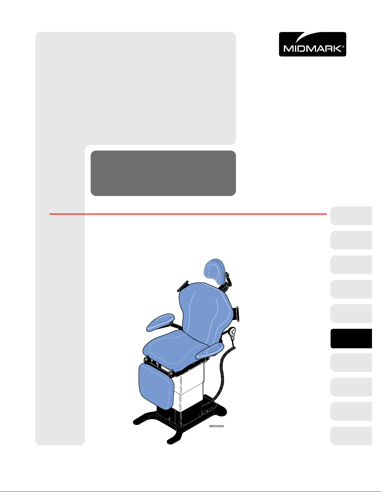
Power Procedure Table
Serial Number Prefixes:
LM, LN, LP, LR & V
Parts Manual
NO LONGER IN PRODUCTION
Some service parts may not
be available for this production
FOR USE BY MIDMARK TRAINED TECHNICIANS ONLY
SF-1604 Part No. 004-0249-00 Rev. J (01/19/12)
419
-011
thru
-006
Page 2

Go To Table Of Contents
RETURN TO TABLE
OF CONTENTS
Page 3

TABLE OF CONTENTS
TABLE OF CONTENTS
Section/Paragraph................................................Page Section/Paragraph ............................................... Page
IMPORTANT INSTRUCTIONS
General Safety Instructions ..........................................iii
Safety Alert Symbols .................................................... iii
Warranty Instructions ................................................. iii
SECTION I GENERAL INFORMATION
1.1 Scope of Manual .......................................... 1-1
1.2 How to Use Manual ...................................... 1-1
1.3 Description of 419 Power
Procedure Table ........................................ 1-1
1.4 Standard Torque Specifications.................... 1-6
1.5 Specifications ............................................... 1-6
1.6 Parts Replacement Ordering........................ 1-8
1.7 Special Tools ................................................ 1-8
SECTION II TESTING AND TROUBLESHOOTING
2.1 Operational Test ........................................... 2-1
2.2 Troubleshooting Procedures......................... 2-5
SECTION III SCHEDULED MAINTENANCE
3.1 Scheduled Maintenance ............................. 3-1
SECTION IV MAINTENANCE/SERVICE
INSTRUCTIONS
4.1 Introduction................................................... 4-1
4.2 PC Control Board Calibration
(Programmable Tables Only)..................... 4-1
4.3 PC Control Board Removal / Installation
(Non-Programmable Tables Only)............. 4-2
4.4 PC Control Board Removal / Installation
(Programmable Tables Only)..................... 4-3
4.5 Tilt Actuator Removal / Installation ............... 4-4
4.6 Tilt Capacitor Removal / Installation ............. 4-7
4.7 Back Actuator Removal / Installation ............ 4-8
4.8 Back Capacitor Removal / Installation........ 4-10
4.9 Foot Actuator Removal / Installation........... 4-11
4.10 Foot Capacitor Removal / Installation......... 4-13
4.11 Base Actuator Removal / Installation.......... 4-14
4.12 Base Capacitor Removal / Installation........ 4-19
4.13 Column Assembly Removal / Installation ...4-20
4.14 Typical Actuator Motor
Removal / Installation .............................. 4-25
4.15 Base Down Limit Switch Removal /
Installation / Adjustment.......................... 4-26
4.16 Base Up Limit Switch Removal /
Installation / Adjustment.......................... 4-27
4.17 Chain Tension Check / Adjustment ............ 4-29
4.18 Eccentric Bearings Adjustment .................. 4-30
4.19 Hand / Foot Control Inlet PC Board
Removal / Installation.............................. 4-32
4.20 Hand Control PC Board
Removal / Installation ............................. 4-33
4.21 Foot Control Top Removal / Installation
(Non-Programmable Units) ..................... 4-34
4.22 Foot Control Top Removal / Installation
(Programmable Units)............................. 4-35
4.23 Foot Control PC Board
Removal / Installation.............................. 4-35
4.24 Typical Foot Control Foot Pedal Switch
Removal / Installation.............................. 4-36
4.25 Typical Foot Control Function Button
Switch Removal / Installation .................. 4-37
4.26 Typical Foot Control Lamp
Removal / Installation.............................. 4-37
4.27 Dbl. Articulating Headrest Stop Pin
Removal / Installation.............................. 4-38
4.28 Headrest Slide Mechanism Adjustment..... 4-39
4.29 Arm Rest Locking Mechanism
Removal / Installation.............................. 4-40
4.30 Back Slide Bearing
Removal / Installation.............................. 4-40
4.31 Foot Rest Extension Limit Switch
Removal / Installation.............................. 4-41
4.32 Foot Actuator Limit Switch
Removal / Installation.............................. 4-42
4.33 Base Actuator Limit Switch
Removal / Installation.............................. 4-44
4.34 AC Receptacle Removal / Installation ........ 4-46
4.35 Fuse Holder Removal / Installation ............ 4-47
4.36 Foot Rest Extension Latch Spring
Removal / Installation.............................. 4-47
4.37 Foot Position Sensor Removal /
Installation /Adjustment
(Programmable Units Only) .................... 4-48
4.38 Tilt Position Sensor Removal /
Installation / Adjustment
(Programmable Units Only) .................... 4-51
4.39 Back Position Sensor Removal /
Installation / Adjustment
(Programmable Units Only) .................... 4-54
4.40 Base Position Sensor Removal /
Installation / Adjustment
(Programmable Units Only) .................... 4-58
(*) Indicates that there has been a serial number break for the illustration
and that there are additional point page(s) following the original page.
© Midmark Corporation 1999 SF-1604 Page i Printed in U.S.A.
Rev. 2/02
Page 4

TABLE OF CONTENTS
Return To Table Of Contents
Section/Paragraph................................................Page Section/Paragraph............................................... Page
SECTION V SCHEMATICS AND DIAGRAMS
5.1 Electrical Schematics /
Wiring Diagrams ....................................... 5-1
5.2 Fuse Specifications ...................................... 5-7
5.3 Error Codes Chart
(Programmable Units Only)....................... 5-7
SECTION VI PARTS LIST
6.1 Introduction................................................... 6-1
6.2 Description of Columns ................................ 6-1
6.3 Torque Specifications And Important
Assembly Notes ........................................ 6-1
Pictorial Index (419-003) ............................6-2.*
Pictorial Index (419-004) ............................6-3.*
Pictorial Index (419-005) ............................6-4.*
Pictorial Index (419-006) .............................. 6-5
Upholstery Kit............................................... 6-6
Articulated Headrest Assembly ...................6-7*
Arm Rest .....................................................6-8*
Backrest Assembly ......................................6-9*
Arm Linkage Components.......................... 6-10
Seat Components ...................................... 6-11
Top to Base Connections ........................... 6-12
Top Electrical Components (115 V. Units).. 6-13
Top Electrical Components (230 V. Units).. 6-14
Foot Components ...................................... 6-15
Program Position Components .................. 6-16
Base Reducer Assembly............................ 6-17
Foot Sensor Components .......................... 6-18
Back Sensor Components ......................... 6-19
Tilt Sensor Components ............................ 6-20
Base Cover Components ........................... 6-21
Base Electrical Comp. (115 V. Units) ......... 6-22
Base Electrical Comp. (230 V. Units) ......... 6-23
Power Inlet Components............................ 6-24
Column Components ................................. 6-25
Column Assembly ...................................... 6-26
Hand Control Assm (Non-Programmable) . 6-27
Hand Control Assm (Programmable) ......... 6-28
Footswitch Assm (Non-Programmable) ..... 6-29
Footswitch Assm (Programmable) ............. 6-30
COMMENTS ............................................................. 7-1
FAX ORDER FORM.................................................. 7-2
(*) Indicates that there has been a serial number break for the illustration
and that there are additional point page(s) following the original page.
© Midmark Corporation 1999 SF-1604 Page ii Printed in U.S.A.
Rev. 7/03
Page 5
TABLE OF CONTENTS
Return To Table Of Contents
General Safety Instructions
Safety First: The primary concern of Midmark Corporation is that this
of the patient and staff in mind. To assure that services
and repairs are completed safely and correctly , proceed
as follows:
(1) Read this entire manual before performing any
services or repairs on this table.
(2) Be sure you understand the instructions con-
tained in this manual before attempting to service or repair this table.
table is maintained with the safety
Safety Alert Symbols
Throughout this manual are safety alert symbols that
call attention to particular procedures. These items are
used as follows:
DANGER
A DANGER is used for an imminently
hazardous ope rating procedure, practice, or condition which, if not correctly followed,
will result in loss of life or serious personal
injury .
CAUTION
A CAUTION is used for a potentially haz-
ardous operating procedure, practice, or
condition which, if not correctly followed, could result
in minor or moderate injury. It may also be used to
alert against unsafe practices.
EQUIPMENT ALE RT
An EQUIPMENT ALERT is used for an
imminently or potentially hazardous operating procedure, practice, or condition which, if not
correctly followed, will or could result in serious, moderate, or minor damage to unit.
NOTE
A NOTE is used to amplify an operating procedure,
practice or condition.
Warranty Instructions
Refer to the Midmark “Limited Warranty” printed in the
Installation and Operation Manual for warranty information. Failure to follow the guidelines listed below will
void the warranty and/or render the 419 Power Procedure Table unsafe for operation.
WARNING
A WARNING is used for a potentially
hazardous ope rating procedure, practice, or condition which, if not correctly followed,
could result in loss of life or serious personal
injury.
• In the event of a malfunction, do not attempt to use
the examination table until necessary repairs have
been made.
• Do not attempt to disassemble table, replace malfunctioning or damaged components, or perform
adjustments unless you are one of Midmark’s
authorized service technicians.
• Do not substitute parts from another manufacturer
when replacing inoperative or damaged components. Use only Midmark replacement parts.
© Midmark Corporation 1999 SF-1604
Page iii
Printed in U.S.A.
Page 6

TABLE OF CONTENTS
Return To Table Of Contents
© Midmark Corporation 1999 SF-1604
Page iv
Printed in U.S.A.
Page 7

SECTION I
Return To Table Of Contents
GENERAL INFORMATION
SECTION I
GENERAL INFORMATION
1.1
This manual contains detailed troubleshooting, scheduled maintenance, maintenance, service instructions,
and a complete illustrated parts breakdown for the
419 (-003 thru -006) Power Procedure Table. This manual covers both programmable and non-programmable
versions of this table. This manual is intended to be
used by Midmark’s authorized service technicians.
Scope of Manual
1.2 How to Use Manual
A. Manual Use When Performing Scheduled Mainte-
nance.
(1) Perform inspections and services listed in
Scheduled Maintenance Chart (Refer to
para 3.1).
(2) If a component is discovered to be faulty or out
of adjustment, replace or adjust component in
accordance with maintenance / service instructions (Refer to para 4.1).
1.3 Description Of 419 (-003 thru -006)
Power Procedure T able
A. General Description (See Figure 1-1).
The 419 Power Procedure Table is a general purpose
examination table designed specifically for performing
general medical examinations and procedures. The
table is available with or without programming. The programmable versions have additional features such as
programmed positioning, a Home function, and audible
warning signals.
Listed below are descriptions of the models available
and their serial number prefixes:
419-003 (LM) .................115 VAC without programming
419-004 (LN).................. 115 VAC with programming
419-005 (LP) .................. 230 VAC without programming
419-006 (LR).................. 230 VAC with programming
B. Manual Use When Unit Is Malfunctioning And
Cause Is Unknown.
(1) Perform an operational test on unit (Refer to
para 2.1).
(2) Perform troubleshooting procedures listed in
Troubleshooting Guide (Refer to para 2.2).
(3) If a component is discovered to be faulty or out
of adjustment, replace or adjust component in
accordance with maintenance / service instructions (Refer to para 4.1).
C. Manual Use When Damaged Component Is Known.
(1) Replace or adjust component in accordance
with maintenance / service instructions (Refer
to para 4.1).
The major serviceable components of the table are:
the tilt actuator, tilt capacitor, back actuator, back capacitor, foot actuator, foot capacitor, base actuator, base
capacitor, base down limit switch, base up limit switch,
PC control board, foot & hand control inlet PC boards,
chain assembly, column assembly, headrest assembly,
non-programmable foot control which includes foot
switches and foot control interface board or a programmable foot control which includes foot switches, a foot
control interface board, indicator L.E.D.’s, and program
control footswitches, and the Foot Extension Crash Protection Circuit which includes the foot actuator limit
switch, foot rest extension limit switch, and base actuator limit switch.
apply to programmable units only:
back position sensor, foot position sensor, and base
reducer assembly which includes base position sensor.
The following serviceable components apply to the
optional hand control:
hand control PC board.
The following serviceable components
tilt position sensor,
hand control switch panel and
© Midmark Corporation 1999 SF-1604
Rev. 2/00
Page 1-1
Printe d in U.S .A.
Page 8

SECTION I
Return To Table Of Contents
GENERAL INFORMATION
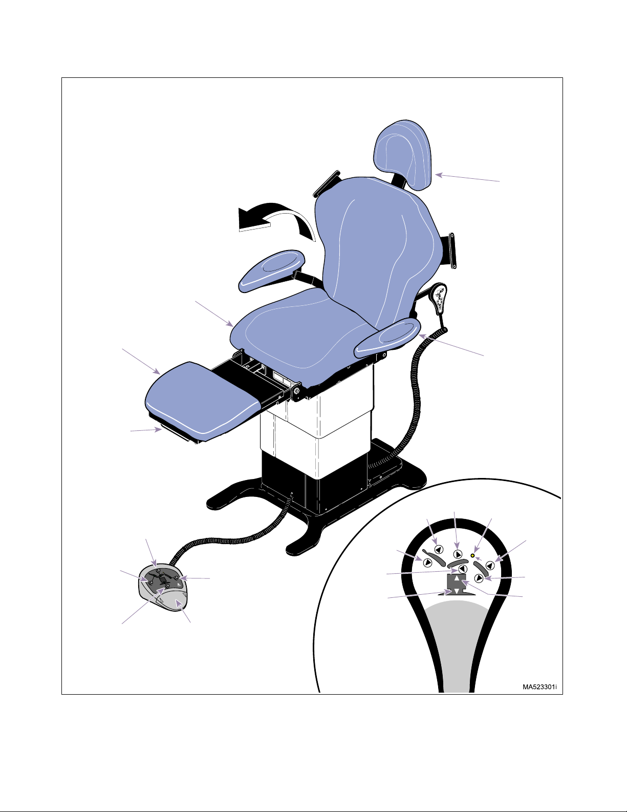
HEADLOCK
ASSEMBLY
FOOT EXTENSION
PROGRAM
CONTROL
FOOT
SWITCHES
(PROGRAMMABLE
FOOT CONTROL
ONLY)
FOOT
CONTROL
FOOT ACTUATOR
LIMIT SWITCH
ACTUATOR
FOOT
POSITION
SENSOR
BASE DOWN
LIMIT SWITCH
LIMIT SWITCH
BASE
CAPACITOR
REDUCER
ASSEMBLY
INDICATOR
L.E.D.'S
(PROGRAMMABLE
FOOT CONTROL
ONLY)
CAPACITOR
FOOT
CAPACITOR
FOOT
BASE
FOOT
SWITCHES
ACTUATOR
BACK
INDICATOR
L.E.D.'S
BACK
POSITION
POSITION
SENSOR
BASE
SENSOR
FOOT INLET
PC BOARD
TILT
BASE
ACTUATOR
COLUMN
ASSEMBLY
CAPACITOR
ACTUATOR
LIMIT SWITCH
PC CONTROL
BOARD
BASE
ACTUATOR
LIMIT SWITCH
CONTROL
PC BOARD
SWITCH PANEL
TILT
TILT
BASE UP
CHAIN
ASSEMBLY
HAND INLET
PC BOARD
BACK
POSITION
SENSOR
HAND
CONTROL
HAND
HAND
CONTROL
MA523501
© Midmark Corporation 1999 SF-1604 Page 1-2 Printed in U.S.A.
Rev. 2/02
Figure 1-1. Major Components
Page 9

SECTION I
Return To Table Of Contents
GENERAL INFORMATION
B. Standard Theory of Operation (See Figures 5-1
thru 5-6 for wiring diagram / electrical schematic)
Electrical power
Line voltage is supplied thru two main fuses to the
table’s PC control board. These fuses prevent possible
damage to the PC control board due to excessive current draw. There is a transformer and associated followon circuitry on the PC control board which reduces the
line voltage to 12 VDC. The 12 VDC provides power to
operate the circuitry on the PC control board, foot control, and hand control.
Manual Operation of Tilt, Back, and Foot Actuator
Assemblies:
When a function is selected using the foot control, the
foot control sends a signal to the PC control board. The
signal causes the appropriate relay on the PC control
board to energize (i.e., if the TILT UP button is
depressed on foot control, the Tilt Up relay on PC control board is energized). Line voltage is continuously
supplied to all relays on PC control board. So, when a
relay is energized, the line voltage flows thru the relay
and is applied across the windings of the actuator
motor, causing it to run. When the foot control button is
released, the relay de-energizes, removing the line voltage from the windings of the actuator motor and causing it to stop running.
The Tilt, Back, and Foot actuators are ball screw driven.
The actuator assemblies contain a pivot point on the
end of the ball screw. If an actuator assembly is run to
the end of its stroke, the ball screw shaft spins inside
the nut, which allows the actuator assembly to run without damaging or advancing the nut.
The Tilt, Back, and Foot actuators have internal braking
mechanisms which use friction to hold the actuator in
place. When the actuator is run, the actuator overcomes
the force of the friction, allowing it to move. When actuator is stopped, friction holds the actuator in place.
Manual Operation Of Base Actuator Assembly:
continuously supplied to the relays on PC control board.
So, when the base up or down relay is energized, the
line voltage flows thru the relay and is applied across
the windings of the actuator motor, causing it to run. At
the same time, line voltage flows thru the brake relay
and is applied across the solenoid coil of the base
brake, causing the brake to disengage. When the foot
control button is released, the relays de-energize,
removing line voltage from the coils of the actuator
motor, causing it to stop and at the same time, removing
line voltage from the solenoid coil of the base actuator
brake, causing the base brake to engage.
The base actuator is different from the other three actuators; it does not freewheel at the end of its stroke limit.
This is because the base actuator operates under
heavier loads. To prevent the base actuator from reaching its stroke limits, which could damage the actuator,
two limit switches are used; a base down limit switch
and a base up limit switch. These limit switches are normally closed (N.C.) switches. When the base actuator
reaches the end of the travel (up or down), the appropriate limit switch is tripped, opening the circuit. The PC
control board then de-energizes the motor relay and
base brake relay, causing the base actuator motor to
stop running and the base brake to engage.
Foot Extension Protection Circuit:
To prevent the foot extension from accidentally being
run into the floor, three limit switches are used: the foot
rest extension limit switch, foot actuator limit switch, and
base actuator limit switch. These limit switches are connected in parallel and table functions will operate normally unless
all three
switches are
open
. If all three
limit switch circuits are open, the PC control board will
prevent movement of Tilt Down, Table Down, and Foot
Down functions and illuminate the Foot Rest Extension
lamp on the hand control until any (one or all) of the limit
switches are closed.
The foot rest extension limit switch (located behind the
foot slide weldment) is a normally open (N.O.) switch.
However, when the foot rest extension is in its fully
retracted position, the limit switch is tripped, creating a
closed circuit.
When a BASE UP or BASE DOWN function is selected
using the foot control, the foot control sends a signal to
the PC control board. The signal causes the base up or
down relay, and the base brake relay on the PC control
board to energize (i.e., if the BASE UP button is
depressed on hand control, the base up and base brake
relays on PC control board energize). Line voltage is
© Midmark Corporation 1999 SF-1604
Rev. 2/00
Page 1-3
The foot actuator limit switch (mounted on the foot actuator) is a normally closed (N.C.) switch. When the foot
section is between -40° and -90°, the limit switch is
tripped, resulting in an open circuit.
Printe d in U.S .A.
Page 10

SECTION I
Return To Table Of Contents
GENERAL INFORMATION
The base actuator limit switch (mounted on the base
actuator) is a normally closed (N.C.) switch. When the
base actuator is between full down and 1/2 way up, the
limit switch is tripped resulting in an open circuit.
General Information:
All actuator motors have a thermal overload switch
which will activate if the actuator is run continuously and
overheats. The actuator motor is not designed for continuous operation; it is designed for intermittent operation. The normal cool off period for the thermal overload
switches is 10 - 20 minutes.
Each actuator motor has a capacitor which provides
start up power and motor run power.
There are two 0.10 amp Time Lag fuses providing overcurrent protection to the input of the PC control board
on the non-programmable table and two 0.15 amp Time
Lag fuses providing over-current protection to the input
of the PC control board on the programmable table.
There is a 5 amp, “Slo-Blo” Time Lag fuse to provide
over-current protection for each function's relays (i.e, Tilt
fuse protects TILT UP and TILT DOWN relays).
C. Program m able Table Theory of Operation (Se e
Figures 5-1 thru 5-6 for wiring diagram / electrical schematic) (Applies only to tables with programmed posit ioning)
Operation Of Programmable Software:
The previous paragraphs have outlined the theory of
operation for manual functions on both the programmable and non-programmable tables. The following paragraphs will describe control system functions on the
programmable tables.
When the table is powered up, the control system initializes the PC control board and then checks for inputs.
There are two functions which can be initiated by the
operator using the foot control; a function to initiate the
“Calibration” mode and a function to initiate the “Clear
Diagnostics Codes” mode. Also, the PC control board
checks if error codes are stored in memory to determine
if the “error” mode should be initiated.
Additionally, there are two functions that may be initiated by depressing switches mounted on the PC control
board; a function to initiate the “Calibration/Clear Data”
mode (SW 2 on PC board) and a function to initiate the
“Program/Fault Clear ” mode (SW 1 on PC board)
The “Calibration” function
be initiated by the tech-
must
nician if a new PC control board or position sensor is
installed, the position sensor is adjusted, the table is not
moving to a programmed position properly, or the table
begins acting erratically. When the calibration mode is
initiated, the PC control board runs all actuators to their
up and down limits and measures the voltage output of
the position sensors at the limits. These voltage values
are stored in the PC control board’s memory and used
as the basis for storing programmed positions into
memory. Also, the error codes for incorrect direction and
no sensor output change are cleared from the PC control board’s memory. If the calibration procedure is not
successful due to a position sensor reading being out of
limits, the error code indicating why will be stored into
the PC control board’s memory along with an error code
indicating the table is not calibrated. The PC control
board emits a 1 second warning beep at 1.5 second
intervals to indicate to the operator that the calibration
procedure is taking place. The calibration procedure is
described in Section IV, Maintenance.
The “Clear Diagnostics Codes” function must be initiated to reset the PC Control Board, after the PC control
board initiates any error code(s). The PC control board
displays the error code(s) by alternately flashing the
PROGRAM lamp and the FOOT REST EXTENSION
lamp to form a code (See Diagnostic code [error code]
operation later in this section). When the table is in the
error code mode, only manual positioning of the table
will work. To resume normal operation, the “Clear Diagnostic Codes” procedure must be completed. If the PC
control board is replaced or the position sensor is
replaced or adjusted, this procedure will not work; in this
case, the “Program/Fault Clear” mode followed by the
Calibration procedure must be performed. This step is
described in the appropriate procedures in Section IV,
Maintenance.
The “Calibration/Clear Data” mode is initiated when it is
desired to clear the PC control board’s memory where
the calibration data is stored. This step is described in
the appropriate procedures in Section IV, Maintenance.
The “Program/Fault Clear” mode is initiated when it is
desired to clear the PC control board’s memory where
the error codes and program position data are stored.
This function should be used if the PC control board
seems locked up or if a position sensor is replaced /
adjusted. The “Program/Fault Clear” function is
described in the appropriate procedures in Section IV,
Maintenance.
© Midmark Corporation 1999 SF-1604
Rev. 2/00
Page 1-4
Printe d in U.S .A.
Page 11

SECTION I
Return To Table Of Contents
GENERAL INFORMATION
Operation of Home Position Function:
When the operator presses the Home position button,
the PC control board lowers the base actuator until the
base down limit switch is tripped. The Home position
button can be pressed and released; it does not have to
be held down to continue movement. If the base down
limit switch is not detected as being tripped (open circuit) within 18 seconds from the time the Home position
button was pressed, the PC control board de-energizes
the base actuator. If Base Up function button is pressed
while the table is moving toward the Home position, the
Home position function is terminated and Base Up is
initiated until button is released.
Stop Function Operation:
When the Stop button is pressed, the PC control board
terminates all functions, stopping table movement.
When the Stop button is released, the stop mode is cancelled and normal table operation may resume.
Program Mode Operation:
The Program Mode is used to allow the operator to program up to four different table top positions into memory. When the Program Mode button is pressed, the
Program Mode function stays active for five seconds, or
until the operator has pressed one of the four Programmed Position buttons, or the Stop button is
pressed. Also, the Program Mode lamp is illuminated
and stays illuminated until the 5 seconds are up or an
action is taken. When a Programmed Position button is
pressed, the PC control board stores the position sensor voltage values for each axis into its memory. Then, if
the position was stored correctly, the PC control board
flashes the Program Mode lamp three times.
Programmed Position Recall Mode:
To recall a program that is stored in memory, the operator selects one of the four Programmed Position Recall
buttons. The button must be pressed and held to continue table movement. The PC control board determines
which direction to run the actuators by comparing the
current position sensor voltage output for each axis with
the voltage values stored in memory for each axis. The
PC control board energizes the relays for the actuators
requiring movement and then monitors the position sensor voltage output for each axis. When the position sensor voltage output of each position sensor matches the
value stored in the PC control board’s memory, the PC
control board de-energizes the actuator relays.
The PC control board has a maximum run time it allows
for each actuator at any one time. This feature prevents
damage to an actuator motor because of an actuator
relay sticking. When a Programmed Position button is
pressed, the PC control board starts a countdown of the
maximum time allowed for that actuator. At the end of
the countdown, if the button is still sensed by the PC
control board as being pressed, and the actuator has
not reached its limit, the PC control board de-energizes
the relay for the actuator. The maximum run time for
each function is:
• Base Up / Base Down - 18 seconds
• Back Up / Back Down - 25 seconds
• Foot Up / Foot Down - 25 seconds
• Tilt Up / Tilt Down - 25 seconds
During the Programmed Position Recall mode, the PC
control board monitors for several error conditions:
If it is detected that a position sensor’s voltage is
increasing when it should be decreasing, decreasing
when it should be increasing, or data input from a position sensor is invalid, the PC control board stops the
table and sets an error code condition. An explanation
of the error codes is given in para 5.2.
If data stored for the Programmed Position Recall button being pressed is invalid, the Program lamp will flash
on and off until the button is released.
If the base down limit switch or base up limit switch is
tripped (open circuit), the PC control board disables the
Programmed Position Recall mode.
If the Foot Extension Crash Protection Circuit is open
(
all three
control board disables the Program Positioning mode
and the Foot Rest Extension lamp will flash on and off
until the button is released.
If the Stop button is pressed, the Programmed Position
Recall mode is disabled.
Manual Positioning Table Operation:
During manual positioning operation, the control system
for the programmable table works like the control system for the non-programmable table except for some
additional controls:
If there is invalid data inputs from any position sensor,
the PC control board still allows manual positioning
operation.
If conflicting functions are attempted such as Base Up
and Base Down, the PC control board disables all functions until all buttons are released.
limit switch circuits must be
open
), the PC
© Midmark Corporation 1999 SF-1604
Page 1-5
Printe d in U.S .A.
Page 12

SECTION I
Return To Table Of Contents
GENERAL INFORMATION
Diagnostic Code (Error Code) Operation:
When the PC control board detects an error condition, it
disables the Home position and Programmed Position
functions. When these buttons are pressed, there is no
movement. By unplugging the table power cord for a
minimum of ten seconds, and then plugging it back in,
the PC control board is put into the “diagnostic code”
mode, described as follows: At power up, if an error
code is stored in memory, the PC control board outputs
the error code to the foot control in the form of a code.
The Program Mode lamp flashes on and then off for the
number of times equal to the first digit of the error code
stored in memory. Then the Foot Extension lamp
flashes on and then off for the number of times equal to
the second digit of the error code stored into memory.
The PC control board then waits one second, repeats
the error code a second time, then waits one second
and repeats the error code a third time. The next error
code is also displayed three times consecutively. This is
repeated until all error codes have been displayed.
Then, the PC control board continuously displays the
error codes on the foot control until a manual function is
selected.
Position Sensor Operation:
There are position sensors mounted to pivot points on
the Back, Tilt, and Foot axis and a position sensor
mechanism (called a base reducer assembly) attached
to the column assembly for the base function. As each
axis moves, the corresponding position sensor’s inner
wheel rotates with the axis. The position sensor is a
variable resistor which changes resistance in a linear
manner when rotated. So when the axis moves, the
position sensor’s voltage output changes, due to its
resistance change, based upon how far the axis has
moved. The PC control board interprets the voltage
value to determine the location of an axis. When a programmed position is programmed by the operator, the
PC control board stores each sensor’s voltage value
into memory. When the operator wishes to return to that
stored position later, the programmed position button for
the desired programmed position is depressed. The PC
control board determines the current position the table
based on the voltage output of the position sensors, and
then determines which axis’ must be moved and in what
direction. The PC control board energizes the relays for
these actuators and moves the table section(s) to the
desired programmed position. The PC control board
stops the actuators when the voltage value of the position sensors matches the values stored in the PC control board’s memory.
1.4 Standard Torque Specifications
The following torque specifications in Table 1-1 apply to
the various hardware used on the unit unless otherwise
listed elsewhere in the service procedures or parts illustrations:
Table 1-1. Torque Specifications
Hardware Size Torque Values
#6 ............................ 11 to 21 inch / lbs. (1.2 to 2.3 N•m)
#8 ............................ 20 to 30 inch / lbs. (2.2 to 3.3 N•m)
#10 .......................... 32 to 42 inch / lbs. (3.6 to 4.8 N•m)
1/4 inch ................... 75 to 85 inch / lbs. (8.5 to 9.6 N•m)
5/16 inch .................18 to 22 ft. / lbs. (24.4 to 29.8 N•m)
3/8 inch ...................31 to 35 ft. / lbs. (42.0 to 47.5 N•m)
1/2 inch ...................50 to 60 ft. / lbs. (67.8 to 81.4 N•m)
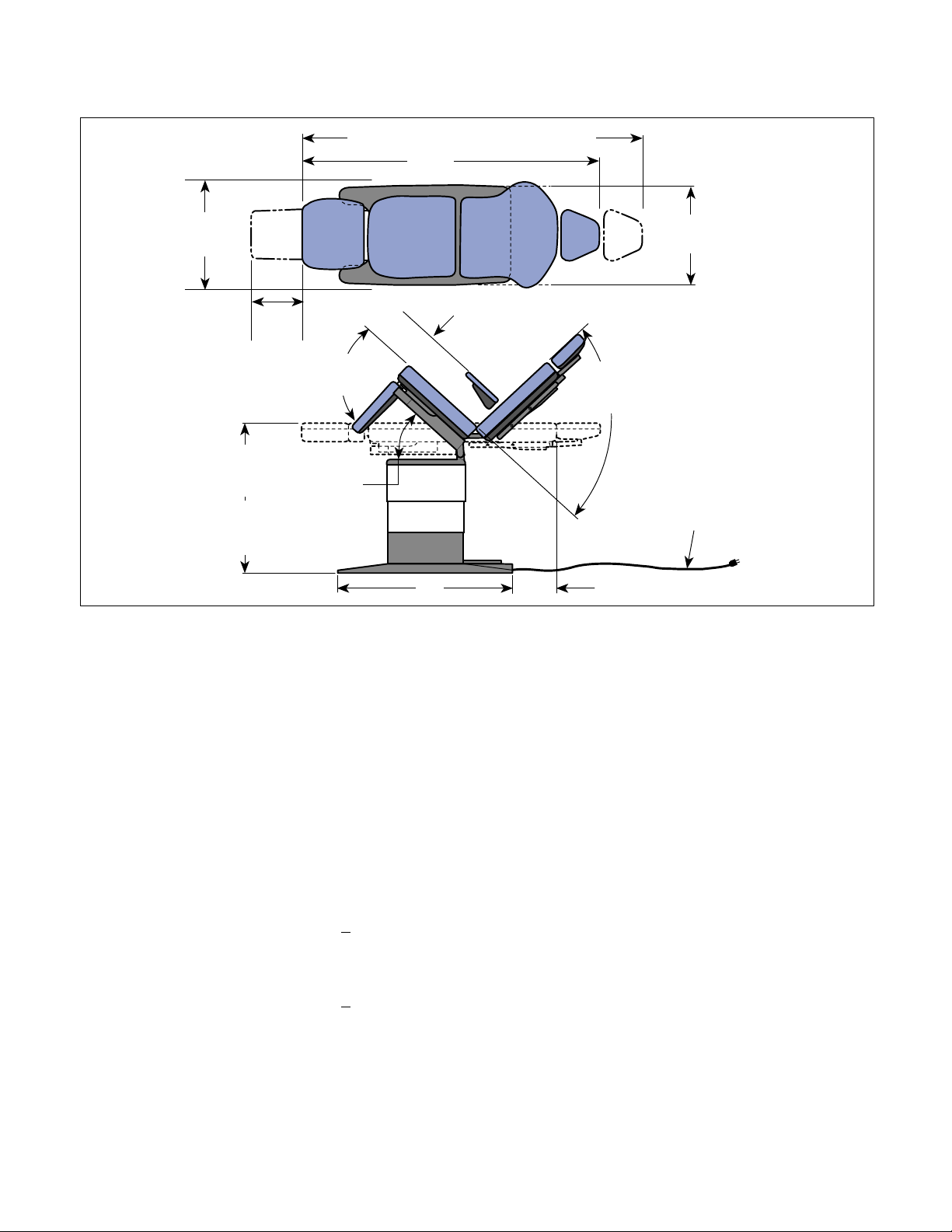
1.5 Specifications
Factual data for the 419 Power Procedure Table is provided in Table 1-2. Also, see Figure 1-2.
Table 1-2. Specifications
Description Data
Weight:
Without Shipping Carton.................515 lbs. (233.6 kg)
With Shipping Carton...................... 550 lbs. (249.5 kg)
Shipping Carton: ..... 54 in. "L" x 32 in. "W" x 33 in. "H"
(137.1 cm x 81.2 cm x 83.8 cm)
Maximum Patient Load: .................. 325 lbs. (147.4 kgs)
Dimensions (See Figure 1-2):
Table Top Length (w/headrest retracted)
(w/back down & foot up) ..............65.0 in. (165.1 cm)
(headrest extended)
Dbl. Articulating Headrest ....... adds 11 in. (27.9 cm)
Triple Articulating Headrest..... adds 15 in. (38.1 cm)
Footrest Extension (adjustable) .... adds 0.0 in to 8.0 in
(0 cm to 20.3 cm)
Table Top Width ...................................23 in. (54.4 cm)
Overall Width .......................................24 in. (61.0 cm)
Table Top Positioning:
Table Top Height ...................... 22 in. to 40 in. ±0.5 in.
(Adjustable) (55.9 +
Back Section ....................... 0° (horizontal) to +85° +
Foot Section......................... 0° (horizontal) to -90° +
Tilt Range...............0° (horizontal) to +30° +
1.3 cm to 101.6 + 1.3 cm)
5°
5°
5° (foot up)
© Midmark Corporation 1999 SF-1604 Page 1-6 Printed in U.S.A.
Rev. 2/02
Page 13
SECTION I
Return To Table Of Contents
GENERAL INFORMATION
Dbl. Articulating Headrest 76" (193.0cm)
Triple Articulating Headrest 80" (203.2 cm)
65
"
(165.1 cm)
23"
58.4
(
(TABLE
cm)
)
40"
(+/- 5")
(101.6 cm)
(MAX.)
22"
(+/- 5")
(55.9 cm)
(MIN.)
8"
(20.3 cm)
90°
(+/- 5°)
(MAX.)
30°
(+/- 5")
(MAX.)
REMAIN HORIZONTAL WITH SEAT
+/- 5
° AS BACK SECTION IS
POSITIONED
32"
(81.28 cm)
6.75"
(17.15 cm)
Figure 1-2. Dimensions
85°
(+/- 5°)
(MAX.)
24"
(61 cm)
(BASE)
POWER
CORD
(98.0" [248.9 cm])
MA524101
Table Speeds (@ 60 Hz):
Base Up ..................................... 18 - 31.5 seconds ±3
Back Up.................................................11 seconds ±3
Tilt Up....................................................17 seconds ±3
Foot Up ................................................... 8 seconds ±3
Power Cord:.............................. 98.0 in. (248.9 cm) long
A black jacketed molded cord to fit
IEC appliance inlet with destination
specific attachment plug
Electrical Requirements:
Model 419(-003 & -004)
115 VAC Units ......................115 VAC +
10%, 50/60 Hz
12 amp, single phase
Model 419 (-005 & -006)
230 VAC Units .....................230 VAC +
10%, 50/60 Hz
8 amp, single phase
Duty Cycle: .................................. Intermittent Operation
[15 seconds on/5 minutes
off (motor run time)]
Recommended Circuit:
A separate (dedicated) circuit is recommended for this
table. The table should not be connected to an electrical
circuit with other appliances or equipment unless the
circuit is rated for the additional load.
Classifications: ................ Class 1, Type B, Applied Part,
Ordinary Equipment,
Intermittent Operation
Certifications:
Midmark Corporation ISO-9001 Certified
Model 419(-003 & -004)
115 VAC Units............................................... UL2601-1
CAN/CSA 22.2, #601.1-M90
Model 419 (-005 & -006)
230 VAC Unit......... Complies to the applicable revision
of the MDD 93/42/EEC, Annex VII.
Complies to the applicable requirements
of EN6060-1-1, EN60601-1-2, EN60601-4
© Midmark Corporation 1999 SF-1604 Page 1-7 Printed in U.S.A.
Rev. 2/02
Page 14
SECTION I
MA520001i
MODEL
NUMBER
SERIAL
NUMBER
Return To Table Of Contents
GENERAL INFORMATION
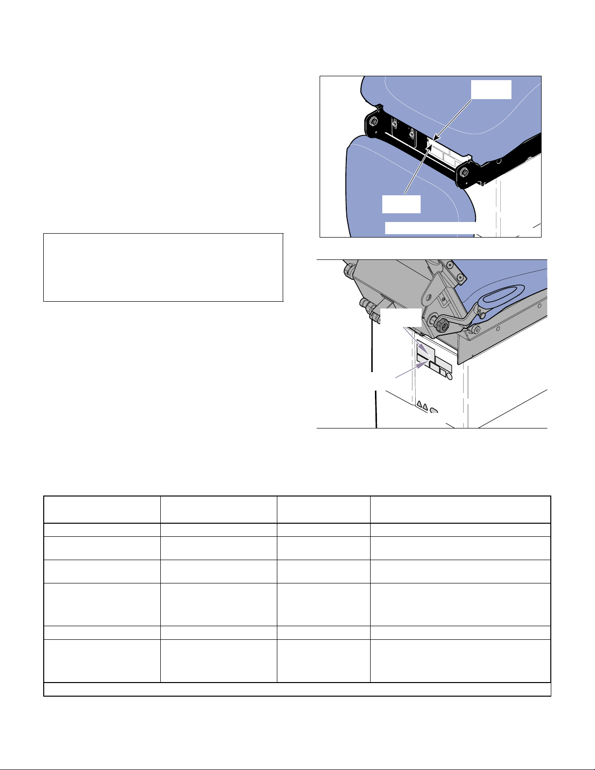
1.6 Parts Replacement Ordering
If a part replacement is required, order the part directly
from the factory as follows:
(1) Refer to Figure 1-3 to determine the location of
the model number and serial number of the unit
and record this data.
(2) Refer to the Parts List to determine the item
numbers of the parts, part numbers of the parts,
descriptions of the parts, and quantities of parts
needed and record this data (Refer to para 6.1).
NOTE
Ask the Purchasing Department of the company that
owns the unit for this information. Otherwise, this
information may be obtained from the dealer that sold
the unit.
SERIAL
NUMBER
Before: (7/26/2002)
MODEL
NUMBER
MA520000
(3) Determine the installation date of the unit and
record this data.
(4) Call Midmark with the recorded information and
ask for the Medical Products Technical Services
Department. See back cover of this manual for
the phone number or use the Fax Order Form
(See page 7-2 for Fax Order Form).
1.7 Special Tools
Table 1-3 lists all of the special tools needed to repair
the unit, how to obtain the special tools, and the purose
Figure 1-3. Model Number / Serial Number
After: (7/26/2002)
Location
of each special tool.
Description of Special Tool
Multimeter (with testing hooks) * Commercially Available Any Type Used to perform continuity and voltage checks.
Protractor * Commercially Available Any Type Used to check the angle of motion for all movable
T15 Torx Wrench Commercially Available Any Type Used to loosen / tighten the screws securing the
5/16 in. - 18 x 1-1/4 Bolt
(Quantity of 2)
Torque Wrench * Commercially Available Any Type Used to tighten nuts or screws to specified values.
Sensor Holder Tool (tool comes
with a position sensor kit).
Manufacturer’s
Name / Address / Phone
Midmark Corporation
60 Vista Drive
Versailles, Ohio 45380
(937) 526-3662
Midmark Corporation
60 Vista Drive
Versailles, Ohio 45380
(937) 526-3662
* Tool should be calibrated annually to ensure proper specifications are met.
Manufacturer’s
Part Number
table top sections.
position sensors, allowing adjustments to be made.
505-702308 Used to remove tension from eccentric bearings so
they may be adjusted.
046-0008-00 Used to hold the 5/16” hex drive while a position
sensor is being installed.
Purpose of Special Tool
© Midmark Corporation 1999 SF-1604 Page 1-8 Printed in U.S.A.
Rev. 2/03
Page 15

TESTING AND TROUBLESHOOTING
Return To Table Of Contents
SECTION II
TESTING AND TROUBLES HOOTING
SECTION II
2.1 Operational Test (See Figure 2-1,
Sheets 1 and 2)
In order to effectively diagnose a malfunction of the 419,
it may be necessary to perform an operational test as
follows:
WARNING
Refer to the Operator Manual for com-
plete instructions on operating the
table. Failure to do so could result in personal
injury.
NOTE
The Operational Test only describes what should
happen when the table is operated. If the table does
something other than described, a problem has been
discovered. Refer to the Troubleshooting Guide to
determine the cause of the problem and its correction.
(1) Plug the table power cord into a properly rated
receptacle.
(2) Using the foot control, operate each table func-
tion (Base Up &Down, Back Up & Down, Tilt Up
& Down, Foot Up & Down)
Range of Motion:
Base down to Base up ......22.38 to 40.38 in.±0.5 in.
(56.8 to 102.5 cm ±1.3 cm)
Back down to Back up........................ 0° to +85° +
Tilt down to Tilt up.............................. 0° to +30° +
Foot down to Foot up ..........................-90° to 0° +
(3) If the table has an optional hand control, repeat
step 2 using the hand control.
(4) Raise foot section to the horizontal position;
then squeeze foot rest extension release handle and pull foot rest extension out as far as it
will go.
(5) Depress BASE UP, and TILT UP buttons on foot
control and hold until each function reaches
maximum height; then depress FOOT DOWN
button and hold until foot section is approximately 1/2 way down.
(6) Depress BASE DOWN, FOOT DOWN, and
TILT DOWN buttons on foot control and hold.
Observe. Table should go approximately 1/2
way down then BASE DOWN, FOOT DOWN,
and TILT DOWN functions should stop and the
Foot Rest Extension lamp on the foot control
should flash.
5°
5°
5°
Observe. When a fucntion is initiated, the table
should move accordingly. No section of the
table top should drift after the foot control pedal
is released. Actuator assembly should not
make excessive squealing noises. Movement
should be steady and should match the speeds
and range of motions listed below:
Table Speeds (@ 60 Hz):
Base down to Base up ......... 18 - 31.5 ±3 seconds
Back down to Back up......................11 ±3 seconds
Tilt down to Tilt up ............................17 ±3 seconds
Foot down to Foot up..........................8 ±3 seconds
© Midmark Corporation 1999 SF-1604 Page 2-1 Printed in U.S.A.
Rev. 2/02
(7) Squeeze foot rest extension handle and push
foot rest extension inward until it locks into its
stowed position; then depress BASE DOWN,
FOOT DOWN, and TILT DOWN buttons on foot
control and hold.
Observe. Foot Rest Extension lamp on foot
control should go out and all functions should
lower to their minimum heights.
(8) Place approximately 325 lbs. (147.4 kg) of
weight on the seat section of the table top.
(9) Depress BASE UP button on foot control.
Observe. The base actuator should not squeal
or make excessive noise when lifting the
weight. The base actuator should be able to lift
the weight. The base actuator should not hum
or make any other type of noise when the table
top reaches maximum height. The base up limit
Page 16

SECTION II
Return To Table Of Contents
TESTING AND TROUBLESHOOTING
switch should trip, stopping the base actuator
from running. The base actuator brake should
engage properly and hold the load without drifting down.
(10) Depress BASE DOWN button on foot control.
Observe. The base actuator should not squeal
or make excessive noise when lowering the
weight. The actuator assembly should not hum
or make any other type of noise when the table
top reaches its minimum height. The base down
limit switch should trip, stopping the base actuator from running.
(11) Remove weight from seat section of table top.
(12) Using either the release button (old style), or
release handle (new style) on the headrest,
reposition headrest at each pivot point.
Observe. Headrest should release and move
easily at each pivot point. Headrest should lock
securely into position when button is released
or handle is returned to locked position.
(13) Slide the headrest assembly in and out of the
headrest slide mechanism releasing at various
positions to observe.
Observe. Headrest assembly should not move
out of position on its own, or require excessive
force to be positioned.
(14) Pull outward on arm rest knob and rotate arm
rest 180°.
Observe. Arm rest should rotate freely when
release knob is pulled, and lock securely in
place 180° from point of origin.
Observe. When the HOME POSITION button
is pressed, the table top should begin to lower.
When the STOP button is pressed, the table top
should stop lowering.
(17) Press the HOME POSITION button and allow
the table top to lower completely.
Observe. When the table top is completely low-
ered, the base actuator should stop running
automatically, indicating that the base down
limit switch is tripped.
(18) If the table has an optional hand control, repeat
steps 15 thru 17 using the hand control.
NOTE
After the PROGRAM button is pressed, the operator
has approximately 5 seconds to press one of the four
Program Position buttons. At the end of the 5 seconds, the PROGRAM MODE lamp turns off, indicating that the program mode has ended.
(19) Press the PROGRAM button and then within 5
seconds, press the Program Position “1” button.
Observe. When the PROGRAM button is
pressed, the PROGRAM MODE lamp will illuminate. Then, when the Program Position “1”
button is pressed, the PROGRAM MODE lamp
will go off and then flash three times to indicate
that the table position data was successfully
stored into the PC control board’s memory.
(20) Use any of the foot control buttons to move the
table top to a new position.
(21) Press and hold the Program Position “1” button
until the table stops moving.
NOTE
The remaining steps apply to programmable units
only. Refer to Figure 2-1 (Sheet 2 of 2) for these
steps.
(15) Depress BASE UP button on foot control until
table reaches its maximum height.
(16) Press the HOME POSITION button for one sec-
ond and then release it. After the table top lowers halfway, press the STOP button.
© Midmark Corporation 1999 SF-1604 Page 2-2 Printed in U.S.A.
Rev. 2/02
Observe. The table top should move back to
the position programmed in step 19.
(22) Repeat steps 19 thru 21 three more times using
Program Position buttons “2”, “3” and then “4”.
(23) If the table has an optional hand control, repeat
steps 19 thru 21 using the hand control.
Page 17
SEAT
Return To Table Of Contents
SECTION
180
SECTION II
TESTING AND TROUBLESHOOTING
HEADREST
RELEASE
BUTTON/HANDLE
o
FOOT
SECTION
FOOT
EXTENSION
RELEASE
HANDLE
BACK
FUNCTION
BUTTON
AND LAMP
TABLE
FUNCTION
BUTTON
AND LAMP
TILT
FUNCTION
BUTTON
AND LAMP
D
M
ARMREST
KNOB
TILT
BACK
UP
BACK
DOWN
BACK
FUNCTION
I
AR
M
BUTTON
AND LAMP
TILT
DOWN
TABLE
DOWN
UP
FOOT REST
EXTENSION
LAMP
FOOT
UP
FOOT
DOWN
TABLE
UP
FOOT
PEDAL
© Midmark Corporation 1999 SF-1604 Page 2-3 Printed in U.S.A.
Rev. 2/02
Figure 2-1. Operational Test (Sheet 1 of 2)
Page 18
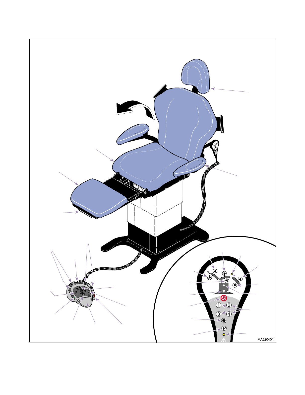
SECTION II
Return To Table Of Contents
TESTING AND TROUBLESHOOTING
180
SEAT
SECTION
HEADREST
RELEASE
BUTTON/HANDLE
o
FOOT
SECTION
FOOT REST
EXTENTION
RELEASE
HANDLE
PROGRAMMED
POSITION
BUTTONS
AND LAMPS
BACK
FUNCTION
BUTTON
AND LAMP
HOME
FUNCTION
BUTTON
AND LAMP
PROGRAMMED
AND LAMPS
PROGRAM
BUTTON
P
2
1
MA
R
D
MI
TABLE
FUNCTION
BUTTON
AND LAMP
POSITION
BUTTONS
3
4
FOOT
PEDAL
TILT
FUNCTION
BUTTON
AND LAMP
FOOT
FUNCTION
BUTTON
AND LAMP
STOP
BUTTON
BACK
DOWN
TILT
DOWN
TABLE
DOWN
STOP
HOME
POSITION
PROGRAM
BACK
UP
TILT
UP
ARMREST
KNOB
FOOT REST
EXTENSION
LAMP
FOOT
UP
FOOT
DOWN
TABLE
UP
PROGRAM
POSTION
BUTTONS
PROGRAM
MODE LAMP
Figure 2-1. Programmable Units Operational Test (Sheet 2 of 2)
© Midmark Corporation 1999 SF-1604 Page 2-4 Printed in U.S.A.
Rev. 2/02
Page 19

SECTION II
Return To Table Of Contents
TESTING AND TROUBLESHOOTING
2.2 Troubleshooting Procedures
Table 2-1 is a Troubleshooting Guide which is used to
Table 2-1. Troubleshooting Guide
Problem Symptom Probable Cause Check Correction
Table will not operate when
any of the functions on the
foot control or hand control
are selected.
No actions can be initiated
from hand control.
When any foot/hand control button is pressed,
nothing happens.
Table has power, but no
functions can be initiated
from hand control. Foot
control works properly.
Power cord is not plugged
into wall outlet and/or AC
receptacle.
Facility circuit breaker providing power to unit is
tripped.
Fuse(s) at power inlet blown. Perform continuity check
Wire connections loose. Check all wiring connec-
Primary fuse(s) on PC control board is blown.
PC control board is malfunctioning.
Fuse holders malfunctioning. Perform continuity check
AC receptacle malfunctioning.
Coil cord is not plugged into
hand control or receptacle
on table properly.
Hand control switch panel is
malfunctioning.
Hand control PC board is
malfunctioning.
determine the cause of the malfunction.
Check to see if power
cord is plugged in.
Check to see if facility circuit breaker for unit is
tripped. One way of
checking this is to plug a
lamp into wall outlet that
table was plugged into.
on fuses.
tions from power cord to
terminal block. Perform
continuity check on
wires. Use multimeter to
check for proper voltage
levels. See Figures 5-1
thru 5-6.
Refer to Figure 2-2 for
this check. Perform continuity check on fuses.
Replace suspect PC control board with known
working PC control
board.
on fuse holder.
Perform continuity check
on AC inlet.
Check if coil cord is
plugged in properly.
Replace suspect hand
control switch panel with
known working hand control switch panel.
Replace suspect hand
control PC board with
known working hand control PC board.
Plug power cord into facility
wall outlet and/or AC receptacle.
If facility circuit breaker is
tripped, determine what
caused the circuit breaker to
trip, correct the problem, and
then reset / replace the circuit
breaker.
Replace blown fuse(s). Refer
to para 5.2.
Clean any dirty connections.
Tighten any loose connections. Replace any damaged
connections.
Replace blown fuse(s). Refer
to para 5.2.
Replace PC control board.
Refer to para 4.3 or 4.4.
Replace fuse holder. Refer to
para 4.33.
Replace AC receptacle. Refer
to para 4.34
Plug coil cord into hand control or receptacle on table.
Clean any dirty connections.
Replace hand control switch
panel. Refer to para 4.20
Replace hand control PC
board. Refer to para 4.20.
© Midmark Corporation 1999 SF-1604
Page 2-5
Printe d in U.S .A.
Page 20

Problem Symptom Probable Cause Check Correction
Return To Table Of Contents
No actions can be initiated
from hand control.
- Continued
One or more functions cannot be initiated from hand
control.
No actions can be initiated
from foot control.
Table 2-1. Troubleshooting Guide - Continued
Table has power, but no
functions can be initiated
from hand control. Foot
control works properly.
- Continued
Some functions may be initiated with hand control,
but at least one may not.
Table has power, but no
functions can be initiated
from foot control. Hand
control works properly.
TESTING AND TROUBLESHOOTING
Control inlet PC board is
malfunctioning.
Cord running from control
inlet PC board to PC control
board is disconnected or
broken.
PC control board is malfunctioning.
Hand control switch panel is
malfunctioning (switch membrane is malfunctioning).
Hand control PC board is
malfunctioning.
Fuse for non-operating (suspect) function is blown.
Relay for non-operating
(suspect) function is malfunctioning.
Coil cord is not plugged into
foot control or receptacle on
table properly.
Foot control PC board is
malfunctioning.
Control inlet PC board is
malfunctioning.
Plug foot control into suspect control inlet PC
board and check for
proper operation
Check cord to see if it is
properly connected.
Replace suspect cord
with known working cord
or perform continuity
check on cord.
Replace suspect PC control board with known
working PC control
board.
Replace suspect hand
control switch panel with
known working hand control switch panel.
Plug foot control into suspect control inlet PC
board and check for
proper operation
Refer to Figure 2-2 for
this check. Perform continuity check on suspect
fuse.
Refer to Figure 2-2 for
this check. When hand
control button is pressed,
observe relay L.E.D’s on
PC control board. The
L.E.D. for the function
which was selected
should illuminate to indicate that its relay is operating correctly.
Check if coil cord is
plugged in properly.
Plug hand control into
suspect control inlet PC
board and check for
proper operation.
Replace suspect control
inlet PC board with
known working control
PC board.
SECTION II
If necessary, replace control
inlet PC board. Refer to para
4.19.
Replace cord.
Replace PC control board.
Refer to para 4.3 or 4.4..
Replace hand control switch
panel. Refer to para 4.20.
If necessary, replace hand
control PC board. Refer to
para 4.20.
Replace blown fuse(s). Refer
to para 5.2.
If relay L.E.D. does not illuminate properly, replace PC control board. Refer to para 4.3 or
4.4.
Plug coil cord into foot control
or receptacle on table. Clean
any dirty connections.
Replace foot control PC
board. Refer to para 4.23.
Replace control inlet PC
board. Refer to para 4.19.
© Midmark Corporation 1999 SF-1604
Page 2-6
Printe d in U.S .A.
Page 21

Problem Symptom Probable Cause Check Correction
Return To Table Of Contents
No actions can be initiated
from foot control.
- Continued
BACK UP and BACK
DOWN functions do not
work. All other functions
work.
Table 2-1. Troubleshooting Guide - Continued
Table has power, but no
functions can be initiated
from foot control. Hand
control works properly.
- Continued
Some functions may be initiated with foot control, but
at least one may not.
When BACK UP and
BACK DOWN buttons are
pressed, table will not
move (all other functions
work).
TESTING AND TROUBLESHOOTING
Cord running from control
inlet PC board to PC control
board is disconnected or
broken.
PC control board is malfunctioning.
A footswitch for a function is
malfunctioning.
Foot control PC board is
malfunctioning.
Fuse for non-operating (suspect) function is blown.
Relay for non-operating
(suspect) function is malfunctioning.
Back capacitor is weak or
blown.
Thermal overload switch in
back actuator motor is activated.
5 amp BACK fuse for BACK
UP and BACK DOWN functions is blown.
Wire connections loose. Check all wiring connec-
Back actuator assembly is
malfunctioning.
Check cord to see if it is
properly connected.
Replace suspect cord
with known working cord
or perform continuity
check on cord.
Replace suspect PC control board with known
working PC control
board.
Perform a continuity
check on footswitch.
Replace suspect foot
control interface board
with known working foot
control interface board.
Refer to Figure 2-2 for
this check. Perform continuity check on suspect
fuse.
Refer to Figure 2-2 for
this check. When a footswitch is depressed,
observe relay L.E.D’s on
PC control board. The
L.E.D. representing the
function which was
selected should illuminate to indicate its relay
is operating correctly.
Replace suspect back
capacitor with known
working back capacitor.
_ Wait 10 to 20 minutes to allow
Refer to Figure 2-2 for
this check. Perform a
continuity check on 5
amp BACK fuse.
tions to back actuator
assembly.
Replace suspect back
actuator assembly with
known working back
actuator assembly.
SECTION II
Replace cord.
Replace PC control board.
Refer to para 4.3 or 4.4.
Replace footswitch. Refer to
para 4.25.
Replace foot control PC
board. Refer to para 4.23.
Replace blown fuse(s). Refer
to para 5.2.
If relay L.E.D. does not illuminate properly, replace PC control board. Refer to para 4.3 or
4.4.
Replace back capacitor. Refer
to para 4.8.
back actuator motor to cool.
Replace blown fuse(s). Refer
to para 5.2.
Clean any dirty connections.
Tighten any loose connections. Replace any damaged
connections.
Replace actuator motor or
back actuator assembly. Refer
to para 4.14 or 4.7.
© Midmark Corporation 1999 SF-1604
Page 2-7
Printe d in U.S .A.
Page 22

Problem Symptom Probable Cause Check Correction
Return To Table Of Contents
BACK UP and BACK
DOWN functions do not
work. All other functions
work. - Continued
TILT UP and TILT DOWN
functions do not work. All
other functions work.
TABLE UP and TABLE
DOWN functions do not
work. All other functions
work.
Table 2-1. Troubleshooting Guide - Continued
When BACK UP and
BACK DOWN buttons are
pressed, table will not
move (all other functions
work). - Continued
When TILT UP and TILT
DOWN buttons are
pressed, the table will not
move (all other functions
work).
When TABLE UP and
TABLE DOWN buttons are
pressed, the table will not
move (all other functions
work).
TESTING AND TROUBLESHOOTING
PC control board is malfunctioning.
Tilt capacitor is weak or
blown.
Thermal overload switch in
tilt actuator is activated.
5 amp TILT fuse for TILT UP
and TILT DOWN functions is
blown.
Wire connections loose. Check all wiring connec-
Tilt actuator assembly is
malfunctioning.
PC control board is malfunctioning.
Base capacitor is weak or
blown.
Thermal overload switch in
base actuator motor is activated.
Refer to Figure 2-2 for
this check. Press BACK
UP and then BACK
DOWN button while
observing the PC control
board. The BACK UP
L.E.D. should illuminate
when the BACK UP button is pressed and the
BACK DOWN L.E.D.
should illuminate when
the BACK DOWN button
is pressed. If, not, the PC
control board is malfunctioning.
Replace suspect tilt
capacitor with known
working tilt capacitor.
_ Wait 10 to 20 minutes to allow
Refer to Figure 2-2 for
this check. Perform continuity check on 5 amp
TILT fuse.
tions to tilt actuator
assembly.
Replace suspect tilt actuator assembly with
known working tilt actuator assembly.
Refer to Figure 2-2 for
this check. Press TILT
UP and then TILT DOWN
button while observing
the PC control board.
The TILT UP L.E.D.
should illuminate when
the TILT UP button is
pressed and the TILT
DOWN L.E.D. should illuminate when the TILT
DOWN butt on is press ed.
If not, the PC control
board is malfunctioning.
Replace suspect base
capacitor with known
working base capacitor.
_ Wait 10 to 20 minutes to allow
SECTION II
Replace PC control board.
Refer to para 4.3 or 4.4.
Replace tilt capacitor. Refer to
para 4.6.
tilt actuator motor to cool.
Replace blown fuse(s). Refer
to para 5.2.
Clean any dirty connections.
Tighten any loose connections. Replace any damaged
connections.
Replace actuator motor or tilt
actuator assembly. Refer to
para 4.14 or 4.5.
Replace PC control board.
Refer to para 4.3 or 4.4.
Replace base capacitor. Refer
to para 4.12.
base actuator to cool.
© Midmark Corporation 1999 SF-1604
Page 2-8
Printe d in U.S .A.
Page 23

Problem Symptom Probable Cause Check Correction
Return To Table Of Contents
TABLE UP and TABLE
DOWN functions do not
work. All other functions
work. - Continued
FOOT UP and FOOT
DOWN functions do not
work. All other functions
work.
Table 2-1. Troubleshooting Guide - Continued
When TABLE UP and
TABLE DOWN buttons are
pressed, the table will not
move (all other functions
work). - Continued
When FOOT UP and
FOOT DOWN buttons are
pressed, the table will not
move (all other functions
work).
TESTING AND TROUBLESHOOTING
5 amp BRAKE/ BASE fuse
for TABLE UP, TABLE
DOWN, and base brake
functions is blown.
Wire connections loose. Check all wiring connec-
Base actuator assembly is
malfunctioning.
PC control board is malfunctioning.
Brake on base actuator is
malfunctioning.
Foot capacitor is weak or
blown.
Thermal overload switch in
foot actuator is activated.
5 amp FOOT fuse for FOOT
UP and FOOT DOWN functions is blown.
Wire connections loose. Check all wiring connec-
Foot actuator assembly is
malfunctioning.
Refer to Figure 2-2 for
this check. Perform continuity check on 5 amp
BRAKE/BASE fuse.
tions to base actuator
assembly and base
brake solenoid.
Replace suspect base
actuator assembly with
known working base
actuator assembly.
Refer to Figure 2-2 for
this check. Press TABLE
UP and then TABLE
DOWN button while
observing the PC control
board. The TABLE UP
L.E.D. and BRAKE/BASE
L.E.D. should illuminate
when the TABLE UP button is pressed and the
TABLE DOWN L.E.D.
and the BRAKE/BASE
L.E.D. should illuminate
when the TABLE DOWN
button is pressed. If not,
the PC control board is
malfunctioning.
_ Replace base actuator. Refer
Replace suspect foot
capacitor with known
working foot capacitor.
_ Wait 10 to 20 minutes to allow
Refer to Figure 2-2 for
this check. Perform continuity check on 5 amp
FOOT fuse.
tions to foot actuator
assembly.
Replace suspect foot
actuator assembly with
known working foot actuator assembly.
SECTION II
Replace blown fuse(s). Refer
to para 5.2.
Clean any dirty connections.
Tighten any loose connections. Replace any damaged
connections.
Replace base actuator assembly. Refer to para 4.11.
Replace PC control board.
Refer to para 4.3 or 4.4.
to para 4.11.
Replace foot capacitor. Refer
to para 4.10.
foot actuator motor to cool.
Replace blown fuse(s). Refer
to para 5.2.
Clean any dirty connections.
Tighten any loose connections. Replace any damaged
connections.
Replace actuator motor or foot
actuator assembly. Refer to
para 4.14 or 4.9.
© Midmark Corporation 1999 SF-1604
Page 2-9
Printe d in U.S .A.
Page 24

Problem Symptom Probable Cause Check Correction
Return To Table Of Contents
FOOT UP and FOOT
DOWN functions do not
work. All other functions
work. - Continued
BACK UP function works,
but BACK DOWN function
does not or BACK DOWN
function works, but BACK
UP function does not. All
other functions work.
TILT UP function works but
TILT DOWN function does
not or TILT DOWN function
works, but TILT UP function does not. A ll other
functions work.
Table 2-1. Troubleshooting Guide - Continued
When FOOT UP and
FOOT DOWN buttons are
pressed, the table will not
move (all other functions
work). - Continued
One function operates
properly, but the other
does not.
One function operates
properly, but the other
does not.
TESTING AND TROUBLESHOOTING
PC control board is malfunctioning.
Wire connections loose. Check all wiring connec-
Back actuator assembly is
malfunctioning.
PC control board is malfunctioning (relay for up or down
function is malfunctioning).
Hand control switch panel of
hand control is malfunctioning (switch membrane is
malfunctioning).
BACK UP or BACK DOWN
footswitch is malfunctioning.
Wire connections loose. Check all wiring connec-
Tilt actuator assembly is
malfunctioning.
Refer to Figure 2-2 for
this check. Press FOOT
UP and then FOOT
DOWN button while
observing the PC control
board. The FOOT UP
L.E.D. should illuminate
when the FOOT UP button is pressed and the
FOOT DOWN L.E.D.
should illuminate when
the FOOT DOWN button
is pressed. If not, the PC
control board is malfunctioning.
tions to back actuator
assembly.
Replace suspect back
actuator assembly with
known working back
actuator assembly.
Refer to Figure 2-2 for
this check. Press BACK
UP and then BACK
DOWN button while
observing the PC control
board. The BACK UP
L.E.D. should illuminate
when the BACK UP button is pressed and the
BACK DOWN L.E.D.
should illuminate when
the BACK DOWN button
is pressed. If not, the PC
control board is malfunctioning.
Replace suspect hand
control switch panel with
known working hand control switch panel.
Perform a continuity
check on suspect foot
switch.
tions to tilt actuator
assembly.
Replace suspect tilt actuator assembly with
known working tilt actuator assembly.
SECTION II
Replace PC control board.
Refer to para 4.3 or 4.4.
Clean any dirty connections.
Tighten any loose connections. Replace any damaged
connections.
Replace actuator motor or
back actuator assembly. Refer
to para 4.14 or 4.7.
Replace PC control board.
Refer to para 4.3 or 4.4.
Replace hand control switch
panel. Refer to para 4.20.
Replace footswitch. Refer to
para 4.25.
Clean any dirty connections.
Tighten any loose connections. Replace any damaged
connections.
Replace actuator motor or tilt
actuator assembly. Refer to
para 4.14 or 4.5.
© Midmark Corporation 1999 SF-1604
Page 2-10
Printe d in U.S .A.
Page 25

Problem Symptom Probable Cause Check Correction
Return To Table Of Contents
TILT UP function works but
TILT DOWN function does
not or TILT DOWN function
works, but TILT UP function does not. All other
functions work.
- Continued
TABLE UP function works,
but TABLE DOWN function does not or TABLE
DOWN function works, but
TABLE UP function does
not. All other functions
work.
Table 2-1. Troubleshooting Guide - Continued
One function operates
properly, but the other
does not. - Continued
One function operates
properly, but the other
does not.
TESTING AND TROUBLESHOOTING
PC control board is malfunctioning (relay for up or down
function is malfunctioning).
Hand control switch panel of
hand control is malfunctioning (switch membrane is
malfunctioning).
TILT UP or TILT DOWN footswitch is malfunctioning.
Wire connections loose. Check all wiring connec-
Either base down limit switch
or base up limit switch is
malfunctioning.
Base actuator assembly is
malfunctioning.
PC control board is malfunctioning (relay for up or down
function is malfunctioning).
Hand control switch panel of
hand control is malfunctioning (switch membrane is
malfunctioning).
Refer to Figure 2-2 for
this check. Press TILT
UP and then TILT DOWN
button while observing
the PC control board.
The TILT UP L.E.D.
should illuminate when
the TILT UP button is
pressed and the TILT
DOWN L.E.D. should illuminate when the TILT
DOWN butt on is press ed.
If not, the PC control
board is malfunctioning.
Replace suspect hand
control switch panel with
known working hand control switch panel.
Perform a continuity
check on suspect footswitch.
tions to base actuator.
Perform continuity check
on N.C. limit switches
(limit switch tripped =
open).
Replace suspect base
actuator assembly with
known working base
actuator assembly.
Refer to Figure 2-2 for
this check. Press TABLE
UP and then TABLE
DOWN button while
observing the PC control
board. The TABLE UP
L.E.D. and BRAKE/BASE
L.E.D. should illuminate
when the TABLE UP button is pressed and the
TABLE DOWN L.E.D.
and the BRAKE/BASE
L.E.D. should illuminate
when the TABLE DOWN
button is pressed. If not,
the PC control board is
malfunctioning.
Replace suspect hand
control switch panel with
known working hand control panel.
SECTION II
Replace PC control board.
Refer to para 4.3 or 4.4.
Replace hand control switch
panel. Refer to para 4.20.
Replace footswitch. Refer to
para 4.25.
Clean any dirty connections.
Tighten any loose connections. Replace any damaged
connections.
Replace base up limit switch
(Refer to para 4.16) or base
down limit switch (Refer to
para 4.15).
Replace base actuator assembly. Refer to para 4.11.
Replace PC control board.
Refer to para 4.3 or 4.4.
Replace hand control switch
panel. Refer to para 4.20.
© Midmark Corporation 1999 SF-1604
Page 2-11
Printe d in U.S .A.
Page 26

Problem Symptom Probable Cause Check Correction
Return To Table Of Contents
TABLE UP function works,
but TABLE DOWN function does not or TABLE
DOWN function works, but
TABLE UP function does
not. All other functions
work. - Continued
FOOT UP function works,
but FOOT DOWN function
does not or FOOT DOWN
function works, but FOOT
UP function does not. All
other functions work.
TA B L E D OW N, FO OT
DOWN, AND TILT DOWN
functions do not work. All
other functions work.
Table 2-1. Troubleshooting Guide - Continued
One function operates
properly, but the other
does not. - Continued
One function operates
properly, but the other
does not.
When TABLE DOWN,
FOOT DOWN, or TILT
DOWN buttons are
pressed, the table will not
move (all other functions
work). Foot Extension lam p
on hand control illuminates.
TESTING AND TROUBLESHOOTING
TABLE UP or TABLE DOWN
footswitch is malfunctioning.
Wire connections loose. Check all wiring connec-
Foot actuator assembly is
malfunctioning.
PC control board is malfunctioning (relay for up or down
function is malfunctioning).
Hand control switch panel of
hand control is malfunctioning (switch membrane is
malfunctioning).
FOOT UP or FOOT DOWN
footswitch is malfunctioning.
Foot rest extension is not
pushed in all the way.
Foot rest extension limit
switch, foot actuator limit
switch, and/or base actuator
limit switch malfunctioning.
PC control board is malfunctioning.
Perform a continuity
check on suspect footswitch.
tions to foot actuator
assembly.
Replace suspect foot
actuator assembly with
known working foot actuator assembly.
Refer to Figure 2-2 for
this check. Press FOOT
UP and then FOOT
DOWN button while
observing the PC control
board. The FOOT UP
L.E.D. should illuminate
when the FOOT UP button is pressed and the
FOOT DOWN L.E.D.
should illuminate when
the FOOT DOWN button
is pressed. If not, the PC
control board is malfunctioning.
Replace suspect hand
control switch panel with
known working hand control switch panel.
Perform a continuity
check on suspect footswitch.
Check that foot rest
extension is pushed in all
the way.
Perform continuity check
on limit switches.
Replace suspect PC
board with known working PC board.
SECTION II
Replace footswitch. Refer to
para 4.25.
Clean any dirty connections.
Tighten any loose connections. Replace any damaged
connections.
Replace actuator motor or foot
actuator assembly. Refer to
para 4.14 or 4.9.
Replace PC control board.
Refer to para 4.3 or 4.4.
Replace hand control switch
panel. Refer to para 4.20.
Replace footswitch. Refer to
para 4.25.
Push foot rest extension in all
the way.
Replace limit switch(es). Refer
to para 4.31, 4.32, or 4.33.
Replace PC board. Refer to
para 4.3 or 4.4.
© Midmark Corporation 1999 SF-1604
Page 2-12
Printe d in U.S .A.
Page 27

Problem Symptom Probable Cause Check Correction
Return To Table Of Contents
The Back, Tilt, or Foot
function drifts by itself.
Base function drifts by
itself.
Table moves fine for light
patient, but will not move or
moves slowly for very
heavy patient.
Whirling or squeaking
noise is heard when an
actuator assembly is being
run.
Excessive sideways play of
table top.
Excessive sideways play of
back section.
Armrest is not operating
properly.
Headrest is not operating
properly.
TESTING AND TROUBLESHOOTING
Table 2-1. Troubleshooting Guide - Continued
Function operates properly otherwise.
Base function operates
properly otherwise.
Heavy patients cause table
to malfunction.
Noisy actuator. Foreign matter on ball screw
Table is not stable and can
be moved from side to
side.
Back section feels loose
and can be moved from
side to side.
Armrest does not lock into
one of its two positions.
Headrest assembly slides
downward on its own or
moves out of position too
easily.
Headrest assembly takes
excessive force to position.
Headrest joints move even
though headlock release
button has not been
depressed.
Actuator is malfunctioning. Replace suspect actuator
Base brake is malfunctioning.
Low voltage is being supplied to table.
Table overloaded with too
heavy of a patient.
Capacitor for suspect function is weak.
threads and / or lack of lubricant.
Eccentric bearing(s) not tight
or chain assemblies are
loose.
Base slide assembly is worn
or deformed.
Table base is not resting
firmly on floor.
Back slide bearing(s) worn
or missing.
Armrest release knob is not
returning due to dir t buildup,
weak spring, or damaged
components.
Headrest slide mechanism
needs adjusted (tightened).
Headrest slide mechanism
needs adjusted (loosened).
Stop pins in headrest joints
not creating a positive lock
due to weak spring, dir t, or
wear of components.
assembly with known
working actuator assembly.
Replace suspect base
actuator with known
working base actuator.
Check voltage at wall
receptacle - should be:
Applies to 419 (-003 &
-004) only:
115 ±10% VAC
Applies to 419 (-005 &
-006) only:
230 ±10% VAC
Maximum weight capacity of table is 325 lbs
(147.4 kg).
Replace suspect capacitor with known working
capacitor.
Che ck fo r forei gn mat ter
on ball screw threads.
Check for lack of lubricant on ball screw
threads.
Check for loose eccentric
bearing(s) and check tension of chain assemblies.
Check condition of base
slide assembly.
Check to verify all four
leveling screws are contacting the floor.
Replace back slide bearing(s).
Check for dirt in mechanism. Check for weak
spring or damaged components.
Check adjustment of
headrest slide mechanism.
Check adjustment of
headrest slide mechanism.
Check for weak springs
or dirt. Also check for
worn components such
as a mushroomed stop
pin or pin stop block.
SECTION II
Replace actuator assembly.
Refer to para 4.5, 4.7, 4.9, or
4.11..
Replace base actuator. Refer
to para 4.11.
Correct low voltage situation
at wall receptacle.
Inform table operator of weight
limitation.
Replace capacitor.
Clean all foreign matter off of
ball screw threads. Coat ball
screw threads with STP treatment oil or equivalent. If actuator assembly is still noisy,
replace it.
Adjust eccentric bearing(s) or
adjust tension of chain assembly. Refer to para 4.17.
Replace base slide assembly.
Refer to para 18.
Adjust the leveling screws;
there is one located under
each corner of the base.
Replace back slide bearing(s).
Refer to para 4.30.
Clean mechanism. If necessary, replace weak spring, or
damaged components. Refer
to para 4.29.
Adjust headrest slide mechanism. Refer to para 4.28.
Adjust headrest slide mechanism. Refer to para 4.28.
Clean headrest components.
Replace any worn or damaged
componets. Lubricate components with a silicone based
lubricant. Refer to para 4.27.
© Midmark Corporation 1999 SF-1604
Page 2-13
Printe d in U.S .A.
Page 28

Problem Symptom Probable Cause Check Correction
Return To Table Of Contents
The Troubleshooting Guide entries belo w apply onl y to the programmable tables (419 -004 and 419-006)
HOME POSITION function does not operate properly. All other functions
work.
Table cannot be programmed or moved to previously programmed
position.
Table 2-1. Troubleshooting Guide - Continued
Nothing happens when the
HOME POSITION button
is pressed.
When HOME POSITION
button is pressed, the base
actuator continues to run/
hum when the table top is
completely lowered (for
approximately another 7 10 seconds).
When operator attempts to
store a position into the PC
control board’s memory, it
is not successful.
TESTING AND TROUBLESHOOTING
Hand control switch panel of
hand control is malfunctioning (switch membrane is
malfunctioning).
HOME POSITION footswitch
is malfunctioning.
Base down limit switch is
tripped.
Base down limit switch is
malfunctioning - stuck
closed.
Base actuator is running so
slow that the minimum table
top height is not reached
before the 18 second time
limit stops the base actuator.
Base down limit switch is
malfunctioning (stuck
closed).
Base down limit switch is out
of adjustment.
Incorrect steps taken for
entry of position.
Hand control switch panel of
hand control is malfunctioning (a switch membrane is
malfunctioning).
Pos iti on “1”, “2”, “3”, “4”, or
PROGRAM footswitch is
malfunctioning.
PC control board cannot
read a position sensor correctly, resulting in an error
code.
PC control board is malfunctioning.
PC control board needs calibrated.
Replace suspect hand
control switch panel with
known working hand control switch panel.
Perform continuity check
on HOME POSITION
footswitch.
Table top is already lowered all the way down,
tripping limit switch.
Perform continuity check
on base down limit switch
(limit switch is N.C. when
not tripped).
Replace the base actuator and / or base capacitor with known working
components.
Perform continuity check
on N.C. base down limit
switch (tripped = open).
Check adjustment of
base down limit switch.
Refer to the Operator’s
manual for proper procedure.
Replace suspect hand
control switch panel with
known working hand control switch panel.
Perform continuity check
on suspect footswitch.
Unplug table for at least
ten seconds, plug table
back in, and then look for
presence of error codes.
Replace suspect PC control board with known
working PC control
board.
_ Perform calibration of PC con-
SECTION II
Replace hand control switch
panel. Refer to para 4.20.
Replace footswitch. Refer to
para 4.25.
Inform operator of minimum
height of table.
Replace base down limit
switch. Refer to para 4.15.
Replace base capacitor. Refer
to para 4.12. If this does not
correct the problem, replace
the base actuator. Refer to
para 4.11.
Replace base down limit
switch. Refer to para 4.15.
Because the base actuator
does not freewheel, it may
have been damaged. Check
and replace if necessary.
Refer to para 4.11.
Adjust base down limit switch.
Refer to para 4.15.
Refer the operator to the
Operator’s manual for proper
procedure.
Replace hand control switch
panel. Refer to para 4.20.
Replace footswitch. Refer to
para 4.25.
If error codes are displayed on
hand control, use error code
chart in Table 5-2 to determine
cause of error or see below in
this Troubleshooting Guide.
Replace PC control board.
Refer to para 4.3 or 4.4.
trol board. Refer to para 4.2.
© Midmark Corporation 1999 SF-1604
Page 2-14
Printe d in U.S .A.
Page 29

Problem Symptom Probable Cause Check Correction
Return To Table Of Contents
Table cannot be programmed or moved to previously programmed
position. - Continued
Table 2-1. Troubleshooting Guide - Continued
Table does not move to its
correct programmed position when Position “1”, “2”,
“3”, or “4” button is
pressed.
Table moves toward the
correct programmed position, but one of the functions stops short.
TESTING AND TROUBLESHOOTING
Foot rest extension is not
pushed in all the way.
No position was programmed into the PC control
board’s memory for that
Position button.
The PC control board cannot
read a position sensor correctly, resulting in an error
code.
PC control board is malfunctioning.
Hand control switch panel of
hand control is malfunctioning (a switch membrane is
malfunctioning).
Pos iti on “1”, “2”, “3”, or “4”
footswitch is malfunctioning.
Foot Section Crash Protection Circuit limit switch(es)
malfunctioning.
The position sensor for the
suspect function is out of
adjustment; the position sensor travels past its limit and
enters a “dead spot” (a dead
spot is where the voltage
output of the sensor does
not change even when its
associated function is moving).
Foot Extension Protection
Circuit limit switch(es) malfunctioning.
Check if the Foot Rest
Extension lamp is flashing; will flash as long as a
Position button remains
pressed and foot extension is not stowed.
Check if the PROGRAM
MODE lamp is flashing; it
will flash when a Program Position button is
pressed which does not
have a valid table position stored into its memory.
Unplug table, plug table
back in, and then
observe hand control for
presence of error codes.
Replace suspect PC control board with known
working PC control
board.
Replace suspect hand
control switch panel with
known working hand control switch panel.
Perform continuity check
on suspect footswitch.
Check continuity of Foot
Section Crash Protection
Circuit limit switches.
Run the function to one
of its limits and connect a
multimeter to the Test
Points for the suspect
position sensor (Refer to
para 4.37, 4.38, 4.39, or
4.40). Then, press a
button for 1/10 second
and observe multimeter
reading to see if it has
changed. If it hasn’t, the
position sensor is in a
dead spot and must be
readjusted. Repeat for
functions other limit.
Check continuity of Foot
Extension Protection Circuit limit switches.
SECTION II
Push foot extension in all the
way.
Inform the operator of the
proper procedure for programming a table top position into
memory for a Position button.
If error codes are displayed on
hand control, use error code
chart in Table 5-2 to determine
cause of error.
Replace PC control board.
Refer to para 4.3 or 4.4.
Replace hand control switch
panel. Refer to para 4.20.
Replace footswitch. Refer to
para 4.25.
Replace limit switch(es). Refer
to para 4.31, 4.32, and/or
4.33.
Adjust the position sensor for
the suspect function. If the
adjustment is not successful,
replace the position sensor.
Refer to para 4.37, 4.38, 4.39,
and/or 4.40.
Replace limit switch(es). Refer
to para 4.31, 4.32, and/or
4.33.
© Midmark Corporation 1999 SF-1604
Page 2-15
Printe d in U.S .A.
Page 30

Problem Symptom Probable Cause Check Correction
Return To Table Of Contents
When Programmed Position button “1”, “2”, “3”, or
“4” is pressed, nothing
happens. All other functions work properly.
Table 2-1. Troubleshooting Guide - Continued
When table is unplugged
(for at least ten seconds)
and then plugged back in,
error code 11
ibration not completed due
to error condition) is displayed on foot/hand control. See Table 5-2 for
explanation of error codes
and how to read them.
When table is unplugged
(for at least ten seconds)
and then plugged back in,
error code 12
received from foot/hand) is
displayed on foot control.
See Table 5-2 for explanation of error codes and how
to read them.
When table is unplugged
(for at least ten seconds)
and then plugged back in,
error code 21
tion sensor output voltage
did not change when
expected during a position
recall) is displayed on foot/
hand control. See Table 52 for explanation of error
codes and how to read
them.
(system cal-
(invalid data
(base posi-
TESTING AND TROUBLESHOOTING
The PC control board has
detected an error condition
such as Foot Section Crash
Protection Circuit is open,
STOP button was pressed,
etc., which has prevented
the system calibration routine from completing successfully.
The PC control board has
detected a problem with the
foot/hand control.
PC control board is malfunctioning.
Base position sensor is out
of adjustment or bolt head to
which position sensor is
attached is loose and is not
rotating properly.
Base position sensor is malfunctioning.
Base reducer assembly is
malfunctioning.
Wiring connections are dirty,
torn, or loose.
_ Perform a new system calibra-
Check the foot control
interface board and hand
control PC board.
Replace PC control
board with known working PC control board.
Check to see if base
position sensor is
adjusted correctly or if
bolt is loose.
Replace base position
sensor with known working base position sensor.
Check to see if the base
reducer assembly is set
up and operating properly.
Check all wiring connections from base position
sensor and PC control
board.
SECTION II
tion. Refer to para 4.2.
Replace foot control PC board
(Refer to para 4.23) or hand
control PC board (Refer to
para 4.20).
Replace PC control board.
Refer to para 4.3 or 4.4.
Adjust the base position sensor. Refer to para 4.40.
Replace base position sensor. Refer to para 4.40.
Repair the base reducer
assembly. Refer to para 4.40.
Clean any dirty connections.
Tighten any loose connections. Replace any damaged
connections.
© Midmark Corporation 1999 SF-1604
Rev. 2/00
Page 2-16
Printe d in U.S .A.
Page 31

Problem Symptom Probable Cause Check Correction
Return To Table Of Contents
When Programmed Position button “1”, “2”, “3”, or
“4” is pressed, nothing
happens. All other functions work properly.
- Continued
Table 2-1. Troubleshooting Guide - Continued
When table is unplugged
(for at least ten seconds)
and then plugged back in,
error code 22
tion sensor output voltage
did not increase or
decrease as expected during system calibration or
position recall) is displayed on foot/hand control. See Table 5-2 for
explanation of error codes
and how to read them.
When table is unplugged
(for at least ten seconds)
and then plugged back in,
error code 23
position not stored due to
A/D conversion error reading base position sensor) is
displayed on foot/hand
control. See Table 5-2 for
explanation of error codes
and how to read them.
When table is unplugged
(for at least ten seconds)
and then plugged back in,
error code 24
sensor output voltage did
not change when expected
during a position recall) is
displayed on foot/hand
control. See Table 5-2 for
explanation of error codes
and how to read them.
(base posi-
(program
(tilt position
TESTING AND TROUBLESHOOTING
Base position sensor is out
of adjustment or bolt head to
which position sensor is
attached is loose and is not
rotating properly.
Base reducer assembly is
malfunctioning.
Base position sensor is malfunctioning.
Wiring connections are dirty,
torn, or loose.
The PC control board is malfunctioning.
Tilt position sensor is out of
adjustment or bolt head to
which position sensor is
attached is loose and is not
rotating properly.
Tilt position sensor is malfunctioning.
Wiring connections are dirty,
torn, or loose.
Check to see if base
position sensor is
adjusted correctly or if
bolt is loose.
Check to see if the base
reducer assembly is set
up and operating properly.
Replace base position
sensor with known working base position sensor.
Check all wiring connections from base position
sensor and PC control
board.
Replace PC control
board with known working PC control board.
Check to see if tilt position sensor is adjusted
correctly or if bolt is
loose.
Replace tilt position sensor with known working
tilt position sensor.
Check all wiring connections from tilt position
sensor and PC control
board.
SECTION II
Adjust the base position sensor. Refer to para 4.40.
Repair the base reducer
assembly. Refer to para 4.40.
Replace base position sensor. Refer to para 4.40.
Clean any dirty connections.
Tighten any loose connections. Replace any damaged
connections.
Replace PC control board.
Refer to para 4.3 or 4.4.
Adjust the tilt position sensor.
Refer to para 4.38.
Replace tilt position sensor.
Refer to para 4.38.
Clean any dirty connections.
Tighten any loose connections. Replace any damaged
connections.
© Midmark Corporation 1999 SF-1604
Rev. 2/00
Page 2-17
Printe d in U.S .A.
Page 32

Problem Symptom Probable Cause Check Correction
Return To Table Of Contents
When Programmed Position button “1”, “2”, “3”, or
“4” is pressed, nothing
happens. All other functions work properly.
- Continued
Table 2-1. Troubleshooting Guide - Continued
When table is unplugged
(for at least ten seconds)
and then plugged back in,
error code 25
sensor output voltage did
not increase or decrease
as expected during system calibration or position
recall) is displayed on foot/
hand control. See Table 51 for explanation of error
codes and how to read
them.
When table is unplugged
(for at least ten seconds)
and then plugged back in,
error code 26
position not stored due to
A/D conversion error reading tilt position sensor) is
displayed on foot/hand
control. See Table 5-1 for
explanation of error codes
and how to read them.
When table is unplugged
(for at least ten seconds)
and then plugged back in,
error code 31
tion sensor output voltage
did not change when
expected during a position
recall) is displayed on foot/
hand control. See Table 51 for explanation of error
codes and how to read
them.
(tilt position
(program
(back posi-
TESTING AND TROUBLESHOOTING
Tilt position sensor is out of
adjustment or bolt head to
which position sensor is
attached is loose and is not
rotating properly.
Tilt position sensor is malfunctioning.
Wiring connections are dirty,
torn, or loose.
The PC control board is malfunctioning.
Back position sensor is out
of adjustment or bolt head to
which position sensor is
attached is loose and is not
rotating properly.
Back position sensor is malfunctioning.
Wiring connections are dirty,
torn, or loose.
Check to see if tilt position sensor is adjusted
correctly or if bolt is
loose.
Replace tilt position sensor with known working
tilt position sensor.
Check all wiring connections from tilt position
sensor and PC control
board.
Replace PC control
board with known working PC control board.
Check to see if back
position sensor is
adjusted correctly or if
bolt is loose.
Replace back position
sensor with known working back position sensor.
Check all wiring connections from back position
sensor and PC control
board.
SECTION II
Adjust the tilt position sensor.
Refer to para 4.38.
Replace tilt position sensor.
Refer to para 4.38.
Clean any dirty connections.
Tighten any loose connections. Replace any damaged
connections.
Replace PC control board.
Refer to para 4.3 or 4.4.
Adjust the back position sensor. Refer to para 4.39.
Replace back position sensor.
Refer to para 4.39.
Clean any dirty connections.
Tighten any loose connections. Replace any damaged
connections.
© Midmark Corporation 1999 SF-1604
Rev. 2/00
Page 2-18
Printe d in U.S .A.
Page 33

Problem Symptom Probable Cause Check Correction
Return To Table Of Contents
When Programmed Position button “1”, “2”, “3”, or
“4” is pressed, nothing
happens. All other functions work properly.
- Continued
Table 2-1. Troubleshooting Guide - Continued
When table is unplugged
(for at least ten seconds)
and then plugged back in,
error code 32
tion sensor output voltage
did not increase or
decrease as expected during system calibration or
position recall) is displayed on foot/hand control. See Table 5-1 for
explanation of error codes
and how to read them.
When table is unplugged
(for at least ten seconds)
and then plugged back in,
error code 33
position not stored due to
A/D conversion error reading tilt position sensor) is
displayed on foot/hand
control. See Table 5-1 for
explanation of error codes
and how to read them.
When table is unplugged
(for at least ten seconds)
and then plugged back in,
error code 34
tion sensor output voltage
did not change when
expected during a position
recall) is displayed on foot/
hand control. See Table 51 for explanation of error
codes and how to read
them.
(back posi-
(program
(foot posi-
TESTING AND TROUBLESHOOTING
Back position sensor is out
of adjustment or bolt head to
which position sensor is
attached is loose and is not
rotating properly.
Back position sensor is malfunctioning.
Wiring connections are dirty,
torn, or loose.
The PC control board is malfunctioning.
Foot position sensor is out of
adjustment or bolt head to
which position sensor is
attached is loose and is not
rotating properly.
Foot position sensor is malfunctioning.
Wiring connections are dirty,
torn, or loose.
Check to see if back
position sensor is
adjusted correctly or if
bolt is loose.
Replace back position
sensor with known working back position sensor.
Check all wiring connections from back position
sensor and PC control
board.
Replace PC control
board with known working PC control board.
Check to see if foot position sensor is adjusted
correctly or if bolt is
loose.
Replace foot position
sensor with known working foot position sensor.
Check all wiring connections from foot position
sensor and PC control
board.
SECTION II
Adjust the back position sensor. Refer to para 4.39.
Replace back position sensor.
Refer to para 4.39.
Clean any dirty connections.
Tighten any loose connections. Replace any damaged
connections.
Replace PC control board.
Refer to para 4.3 or 4.4.
Adjust the foot position sensor.
Refer to para 4.37.
Replace foot position sensor.
Refer to para 4.37.
Clean any dirty connections.
Tighten any loose connections. Replace any damaged
connections.
© Midmark Corporation 1999 SF-1604
Rev. 2/00
Page 2-19
Printe d in U.S .A.
Page 34

Problem Symptom Probable Cause Check Correction
Return To Table Of Contents
When Programmed Position button “1”, “2”, “3”, or
“4” is pressed, nothing
happens. All other functions work properly.
- Continued
STOP function does not
operate properly. All other
functions work.
Table 2-1. Troubleshooting Guide - Continued
When table is unplugged
(for at least ten seconds)
and then plugged back in,
error code 35
tion sensor output voltage
did not increase or
decrease as expected during system calibration or
position recall) is displayed on foot/hand control. See Table 5-1 for
explanation of error codes
and how to read them.
When table is unplugged
(for at least ten seconds)
and then plugged back in,
error code 36
position not stored due to
A/D conversion error reading foot position sensor) is
displayed on foot/hand
control. See Table 5-1 for
explanation of error codes
and how to read them.
Function does not stop
when the STOP button is
pressed.
(foot posi-
(program
TESTING AND TROUBLESHOOTING
Foot position sensor is out of
adjustment or bolt head to
which position sensor is
attached is loose and is not
rotating properly.
Foot position sensor is malfunctioning.
Wiring connections are dirty,
torn, or loose.
The PC control board is malfunctioning.
Hand control switch panel of
hand control is malfunctioning (switch membrane is
malfunctioning).
STOP footswitch is malfunctioning.
Check to see if foot position sensor is adjusted
correctly or if bolt is
loose.
Replace foot position
sensor with known working foot position sensor.
Check all wiring connections from foot position
sensor and PC control
board.
Replace PC control
board with known working PC control board.
Replace suspect hand
control switch panel with
known working hand control switch panel.
Perform continuity check
on STOP footswitch.
SECTION II
Adjust the foot position sensor.
Refer to para 4.37.
Replace foot position sensor.
Refer to para 4.37.
Clean any dirty connections.
Tighten any loose connections. Replace any damaged
connections.
Replace PC control board.
Refer to para 4.3 or 4.4.
Replace hand control switch
panel. Refer to para 4.20.
Replace footswitch. Refer to
para 4.25.
© Midmark Corporation 1999 SF-1604
Rev. 2/00
Page 2-20
Printe d in U.S .A.
Page 35

PROGRAMMABLE PC CONTROL BOARD - 115/230 VAC
Return To Table Of Contents
PRIMARY
FUSES
TILT
DOWN
L.E.D.
TILT
FUSE
SECTION II
TESTING AND TROUBLESHOOTING
TILT
UP
L.E.D.
BACK
DOWN
L.E.D.
BACK
UP
L.E.D.
FOOT
UP
L.E.D.
*
FOOT
DOWN
L.E.D.
*
FOOT
FUSE
BRAKE/BASE
FUSE
NON-PROGRAMMABLE PC CONTROL BOARD - 115/230 VAC
PRIMARY
FUSE
TILT
DOWN
L.E.D.
TILT
UP
L.E.D.
BRAKE
L.E.D.
BASE
DOWN
L.E.D.
BASE
UP
L.E.D.
BACK
FUSE
BASE
UP
L.E.D.
BASE
DOWN
L.E.D.
TILT
FUSE
BACK
DOWN
L.E.D.
Figure 2-2. Fuse and Troubleshooting L.E.D. Location
*On some early units, the Foot Up and Foot Down relays are labeled incorrectly on the PC board (Foot Up relay labeled
Foot Down / Foot Down relay labeled Foot Up). On later units the Foot Up/Down relays are identified by an adhesive label.
© Midmark Corporation 1999 SF-1604
Rev. 12/99
BACK
UP
L.E.D.
BACK
FUSE
FOOT
FUSE
Page 2-21
FOOT
UP
L.E.D.
*
FOOT
DOWN
L.E.D.
BRAKE/BASE
*
FUSE
BRAKE/BASE
L.E.D.
MA503400
Printe d in U.S .A.
Page 36

SECTION II
Return To Table Of Contents
TESTING AND TROUBLESHOOTING
© Midmark Corporation 1999 SF-1604
Page 2-22
Printe d in U.S .A.
Page 37

SCHEDULED MAINTENANCE
Return To Table Of Contents
SECTION III
SCHEDULED MAINTENANCE
SECTION III
3.1 Scheduled Maintenance
periodically on the 419 Power Procedure Table. These
inspections and services should be performed as often
Table 3-1 is a Scheduled Maintenance Chart which lists
as indicated in the chart.
the inspections and services that should be performed
Table 3-1. Scheduled Maintenance Chart
Interval Inspection or Service What to Do
Semi-annually Obvious damage Visually check condition of table for obvious damage such as: cracks in components, missing com-
Fasteners / hardware Check table for missing or loose fasteners / hardware. Replace any missing hardware and tighten
Warning and instructional
decals
Pivot points / moving
parts / accessories
Foot control Check that foot control works correctly. Make sure all footswitches operate properly. Replace any
Hand control (optional) Check that hand control works correctly. Make sure all switch membranes work correctly. If neces-
Ball screws of actuator
assemblies
Drifting of actuator
assemblies
Base actuator limit
switches
Foot rest extension Check that foot extension can be easily extended. Make sure foot rest extension is latched securely
Foot Extension
Protection Circuit
Excessive play in column assembly
Headrest Assembly Check that headrest slide assembly can be positioned while having adequate friction to hold head-
ponents, dents in components, or any other visible damage which would cause the table to be
unsafe to operate or would compromise its performance. Repair table as necessary.
any loose hardware as necessary.
Check for missing or illegible decals (see parts illustrations for decal locations and descriptions).
Replace decals as necessary.
Lubricate all exposed pivot points, moving parts, and accessories with silicone based lubricant.
malfunctioning footswitches. Refer to para. 4.24 or 4.25.
sary, replace hand control switch panel. Refer to para 4.20.
Extend each actuator assembly and wipe ball screw threads down with a rag to remove foreign
matter. Coat as much of the ball screw threads as possible with STP treatment oil or equivalent.
Run each actuator assembly to both ends of its travel a couple of times to spread the oil evenly over
all of the ball screw threads and then remove excess oil. If oil does not correct a squealing actuator
assembly, replace actuator assembly.
Check each actuator assembly for drift. If drifting occurs, replace actuator assembly.
Check that the base up limit switch and the base down limit switch stop the base actuator before it
reaches its up or down limit; the base actuator does not freewheel and can be damaged if it
reaches a limit. Adjust the limit switches if necessary. Refer to para 4.33.
in place when retracted.
Raise the BASE, FOOT, and TILT sections to their maximum height; then pull foot extension out as
far as it will go. Lower FOOT section approximately 1/2 way down, then depress BASE DOWN button on hand control. Base should lower approximately 1/2 way down then stop, and Foot Rest
Extension lamp should flash. BASE DOWN, FOOT DOWN, and TILT DOWN functions should be
inoperable, all other functions should work properly. If necessary, adjust or replace limit switches.
Refer to para 4.31, 4.32, or 4.33.
Check that column assembly does not have excessive side to side play. If necessary, adjust eccentric bearings or tighten chain. Refer to para 4.18.
rest assembly in place. If necessary, adjust friction setting of headrest slide assembly. Refer to
para 4.28.
© Midmark Corporation 1999 SF-1604 Page 3-1 Printed in U.S.A.
Rev. 2/02
Dbl Articulating: Check that headrest release button works properly and that headrest assembly
locks securely in place at both pivot points. Replace headrest components as necessary. Refer to
para 4.27.
Triple Articulating: Check that headrest is adjusted properly. Place 45 lbs (20.4 kg) of static
weight on headrest. Headrest should not drift down. Adjust headrest if necessay. Refer to para
4.xx.
Page 38

SECTION III
Return To Table Of Contents
SCHEDULED MAINTENANCE
Table 3-1. Scheduled Maintenance Chart
Interval Inspection or Service What to Do
Semi-annually Arm Rests Pull release knob and check that arm rests can be positioned easily and lock securely into two posi-
Upholstery Check all upholstery for rips, tears, or excessive wear. Replace cushions as necessary.
Accessories Check that all accessories have all of their components and that they function properly. If neces-
Operational Test Perform an Operational Test to determine if the table is operating within its specifications (Refer to
tions when knob is released. Replace arm rest components as necessary. Refer to para 4.29.
sary, repair or replace the accessory.
para 2.1). Replace or adjust any malfunctioning components.
© Midmark Corporation 1999 SF-1604
Page 3-2
Printe d in U.S .A.
Page 39

MAINTENANCE / SERVICE INSTRUCTIONS
Return To Table Of Contents
4.1 Introduction
WARNING
Refer to the Operator Manual for com-
plete instructions on operating the
table. Failure to do so could result in personal
injury .
NOTE
Perform an operational test on the table after the
repair is completed to confirm the repair was properly
made and that all malfunctions were repaired.
SECTION IV
SECTION IV
MAINTENANCE / SERVICE
1
2
P
2
1
3
3
4
The following paragraphs contain removal, installation,
repair, and adjustment procedures for the table.
4.2 PC Control Board Calibration
(Programmable Tables Only)
A. Clearing PC Control Board Error Code Memory.
NOTE
Be sure to record error code prior to performing clearing procedure. If necessary, refer to Section 5 - para
5.3.
(1) Unplug table power cord from outlet receptacle
for at least ten seconds.
(2) Depress and hold the PROGRAM button (1,
Figure 4-1) while simultaneously plugging the
table power cord into the outlet receptacle.
Observe.
the FOOT REST EXTENSION lamp (3) will
simultaneously illuminate for approximately 5
seconds and then go out.
(3) After the PROGRAM MODE lamp (2) and the
FOOT REST EXTENSION lamp (3) go out,
release the PROGRAM button (1).
Observe.
onds, the PC control board will sound two
beeps, indicating the error codes were successfully cleared from memory. If the two beeps do
not sound, repeat the entire procedure
The PROGRAM MODE lamp (2) and
After approximately 10 to 20 sec-
MIDMARK
Figure 4-1. Clearing PC Control Board Memory
B. Calibrating PC Control Board.
(1) Unplug table power cord from outlet receptacle
for at least ten seconds.
(2) Depress and hold the Position “1” button on
foot/hand control (see Figure 4-2) while simultaneously plugging the table power cord into the
outlet receptacle.
Observe.
ure 4-2) and the FOOT REST EXTENSION
lamp (2) will illuminate for approximately three
seconds and will then go out.
The PROGRAM MODE lamp (1, Fig-
NOTE
When performing the following step, release the Position “1” button within three seconds after the PROGRAM MODE and FOOT REST EXTENSION lamps
go out. Failure to do so will cause the calibration to
fail.
© Midmark Corporation 1999 SF-1604
Rev. 3/00
Page 4-1
Printe d in U.S .A.
Page 40

SECTION IV
Return To Table Of Contents
MAINTENANCE / SERVICE
(3) After the PROGRAM MODE lamp (1) and the
FOOT REST EXTENSION lamp (2) go out,
release Position “1” button.
NOTE
If performing calibration procedure using hand control, it is not necessary to press the DOWN button in
the following step.
(4) Within 5 seconds, press and release the HOME
position button (3) then immediately press and
hold the DOWN pedal (4).
POSITION
1
2
1
1
P
3
2
4
Observe. The PROGRAM MODE lamp (1) and
FOOT REST EXTENSION lamp (2) will illuminate for three seconds and then go out.
(5) After the PROGRAM MODE lamp (1) and the
FOOT REST EXTENSION lamp (2) go out,
release DOWN button (4).
While table top moves through its calibration
routine, apply a steady downward pressure on
the back section to prevent it from “bouncing”
which can cause the calibration to fail.
Observe. The table top will automatically begin
to move; all functions will be run to their limits in
the following order: Table Up, Foot Down, Foot
Up, Tilt Up, Tilt Down, Back Down, Back Up,
and Table Down. When the TABLE DOWN
function is completely lowered, the calibration
routine is complete. Also, the PC control board
will sound a beep every two seconds, indicating
a calibration routine is in progress.
(6) Check the foot/hand control; if the PROGRAM
MODE lamp (1) and FOOT REST EXTENSION
lamp (2) begin to flash, an error condition
occurred which resulted in an unsuccessful calibration; repeat the entire procedure. If the
PROGRAM MODE lamp and FOOT REST
EXTENSION lamp do not begin to flash, the
calibration was successful.
MIDMARK
3
Figure 4-2. PC Control Board Calibration
4
4.3 PC Control Board Removal /
Installation (Non-Programmable
Tables Only)
A. Removal
WARNING
Always disconnect the power cor d fr om
the outlet receptacle before removing
any of the table’s covers/shrouds or making any
repairs to prevent the possibility of electrical
shock. Failure to comply with these instructions
could result in severe personal injury or death.
(1) Unplug table power cord from outlet receptacle.
(2) Remove two screws (1, Figure 4-3) and PC
board cover (2) from base casting (3).
© Midmark Corporation 1999 SF-1604 Page 4-2 Printed in U.S.A.
Rev. 12/01
(3) Tag and disconnect eight wire harnesses (4)
from PC control board (5).
(4) Tag and disconnect two modular cords (6) from
PC control board (5).
Page 41

Figure 4-3. PC Control Board Removal / Installation
Return To Table Of Contents
(Non-program m able tables only)
SECTION IV
MAINTENANCE / SERVICE
4.4 PC Control Board Removal / Installation (Programmable Tables Only)
A. Removal
WARNING
Always disconnect the power cord from
the outlet receptacle before removing
any of the table's covers/shrouds or making any
repairs to prevent the possibility of electrical
shock. Failure to comply with these instructions
could result in severe personal injury or death.
(1) Unplug table power cord from outlet receptacle.
(2) Remove two screws (1, Figure 4-4) and PC
board cover (2) from base casting (3).
(3) Tag and disconnect ten wire harnesses (4) from
PC control board (5).
(4) Tag and disconnect two modular cords (6) from
PC control board (5).
(5) Loosen terminal screws (7); then tag and dis-
connect wires (8) from terminals of PC control
board (5).
(6) Remove six screws (9) and PC control
board (5) from base casting (3).
B. Installation
(1) Install PC control board (5) on base casting (3)
and secure with six screws (9).
(2) Connect wires (8) to terminals of PC control
board (5) and secure by tightening terminal
screws (7). Make sure jumper strips (10) are
installed.
(3) Connect two modular cords (6) to PC control
board (5).
(4) Connect eight wire harnesses (4) to PC control
board (5).
(5) Install PC board cover (2) on base casting (3)
and secure with two screws (1).
(6) Plug table power cord into outlet receptacle.
(5) Loosen terminal screws (7); then tag and dis-
connect wires (8) from terminals of PC control
board (5).
(6) Remove six screws (9) and PC control
board (5) from base casting (3).
B. Installation
(1) Install PC control board (5) on base casting (3)
and secure with six screws (9).
(2) Connect wires (8) to terminals of PC control
board (5) and secure by tightening terminal
screws (7). Make sure jumper strips (10) are
installed.
(3) Connect two modular cords (6) to PC control
board (5).
(4) Connect ten wire harnesses (4) to PC control
board (5).
(5) Depress and hold the PROGRAM / FAULT
CLEAR button (11) while simultaneously plugging in the table power cord into the outlet
receptacle.
© Midmark Corporation 1999 SF-1604
Page 4-3
Printe d in U.S .A.
Page 42

SECTION IV
3
4
IDMARK
P
MA526600
7
2
10
1
9
4
5
3
8
6
4
4
13
11
12
Return To Table Of Contents
MAINTENANCE / SERVICE
Observe.
onds, the PC control board will sound three
beeps to indicate that the PC control board’s
memory has been successfully erased.
(7) Install PC board cover (2) on base casting (3)
and secure with two screws (1).
(8) Calibrate the PC control board (Refer to
para 4.2).
After approximately 10 to 20 sec-
4.5 Tilt Actuator Removal / Installation
A. Removal
(1) Raise TABLE UP function all the way up.
WARNING
Always disconnect the power cord from
the outlet receptacle before removing
any of the table's covers/shrouds or making any
repairs to prevent the possibility of electrical
shock. Failure to comply with these instructions
could result in severe personal injury or dea th.
Figure 4-4. PC Control Board Removal / Installation
(Programmable Tables Only)
Observe.
and the FOOT REST EXTENSION lamp (13)
will simultaneously illuminate for approximately
three seconds and then go out.
(6) After the PROGRAM MODE lamp (12) and
the FOOT REST EXTENSION lamp (13) go
out, release the PROGRAM / FAULT CLEAR
button (11).
The PROGRAM MODE lamp (12)
(2) Unplug table power cord from outlet receptacle.
(3) Remove four screws (1, Figure 4-5) and R.H.
and L.H. outer shrouds (2) from column adapter
weldment (3).
(4) Lower middle outer shroud assembly (4) down
out of way.
(5) Remove screw (1, Figure 4-6), ground wire (2),
and lockwasher (3) from column adapter weldment (4).
(6) Cut two cable ties (A) securing actuator cable to
tilt actuator assembly (5).
(7) Remove two screws (6) and connection
cover (7) from column adapter weldment (4).
(8) Cut cable tie (B) securing wire harnesses to
capacitor mounting bracket (8).
© Midmark Corporation 1999 SF-1604
Rev. 3/00
Page 4-4
Printe d in U.S .A.
Page 43

SECTION IV
Return To Table Of Contents
MAINTENANCE / SERVICE
Figure 4-5. Shrouds Removal / Installation
(9) Disconnect actuator wire (9) from wire (10).
NOTE
Steps 10 thru 13 describe the procedure for 115 VAC
units. Use these steps as a guide for 230 VAC units;
the steps are similar.
(10) Using screwdriver, pry tab (C) of capacitor
mounting bracket (8) outward; then remove tilt
capacitor (11) from capacitor mounting bracket.
(11) Remove cap (12) from tilt capacitor (11).
DANGER
A capacitor contains stored electricity.
Never touch terminals of a capacitor,
even if power has been shut off or disconnected.
Always discharge capacitor before touching
capacitor terminals or wires. Failure to comply
with these instruction could result in serious persona l injur y or de ath.
Figure 4-6. Tilt Actuator Wires
Disconnection / Connection
(12) Discharge tilt capacitor (11).
(13) Tag and disconnect two actuator wires (13)
from terminals of tilt capacitor (11); the yellow
and orange wires do not need to be disconnected.
DANGER
Support foot end of table top while
removing clevis pin to prevent foot end
of table top from falling and striking technician.
Failure to comply with these instructions could
result in serious personal injury.
(14) Remove two e-rings (1, Figure 4-7) and clevis
pin (2) securing base of tilt actuator (3) to column adapter weldment (4).
(15) Raise seat weldment (5) up far enough to get
access to pivot pin (6). Using a block (A), support seat weldment in this position.
© Midmark Corporation 1999 SF-1604
Rev. 3/00
Page 4-5
Printe d in U.S .A.
Page 44

SECTION IV
Return To Table Of Contents
MAINTENANCE / SERVICE
(16) Remove two e-rings (7) from pivot pin (6).
(17) Using a hammer and punch, drive pivot pin (6)
out of seat weldment (5) and remove tilt actuator (3) from table.
(18) Remove nut (8) and ground wire (9) from tilt
actuator (3).
B. Installation
(1) Install ground wire (9, Figure 4-7) on tilt actua-
tor (3) and secure with nut (8).
(2) Install tilt actuator (3) on column adapter weld-
ment (4) and secure with clevis pin (2) and two
e-rings (1).
NOTE
Steps 3 thru 5 describe the procedure for 115 VAC
units. Use these steps as a guide for 230 VAC units;
the steps are similar.
(3) Connect two wires (13, Figure 4-6) to terminals
of tilt capacitor (11).
(4) Install cap (12) on tilt capacitor (11).
(5) Position bottom of tilt capacitor (11) on capaci-
tor mounting bracket (8) and then push the top
of the capacitor inward. Using a screwdriver,
force the tab (C) of the capacitor mounting
bracket down over the catch (D) of the cap (12).
Make sure tilt capacitor is held firmly in place.
(6) Connect actuator wire (9) to wire (10).
(7) Secure bundle of wire harnesses to capacitor
mounting bracket (8) with cable tie (B).
(8) Install connection cover (7) on column adapter
weldment (4) and secure with two screws (6).
(9) Secure actuator cable to tilt actuator (5) with
two cable ties (A).
(10) Install lockwasher (3), and ground wire (2) on
column adapter weldment (4) and secure with
screw (1).
Figure 4-7. Tilt Actuator Removal / Installation
(11) Using spanner holes (B, Figure 4-7), unscrew
adjustable clevis (10) until it is even with top of
actuator rod.
(12) Plug table power cord into outlet receptacle.
(13) Run TILT UP function to extend rod of tilt actua-
tor (3) 3 to 4 in. (7.6 to 10.2 cm).
(14) Remove support block (A); then temporarily
connect tilt actuator (3) to seat weldment (5)
with clevis pin (6).
CAUTION
If tilt actuator does not free wheel at end of
stroke, seat weldment is hitting column
adapter weldment. Do not allow this condition to
exist: premature failure of tilt actuator will result.
© Midmark Corporation 1999 SF-1604
Rev. 3/00
Page 4-6
Printe d in U.S .A.
Page 45

SECTION IV
Return To Table Of Contents
MAINTENANCE / SERVICE
(15) Lower TILT DOWN function all the way down
(until tilt actuator can be heard free wheeling).
(16)
Observe.
with top of column weldment adapter (4). If
seat weldment is parallel with top of column
weldment adapter, go to step 21. If seat weldment is not parallel with top of column weldment adapter, go to step 17.
(17) Extend TILT UP function 3 to 4 in. (7.6 to
10.2 cm).
(18) Remove clevis pin (6) and block seat
weldment (5) in this position.
(19) Using spanner holes (B), screw adjustable cle-
vis (10) in or out as determined necessary in
step 16.
(20) Repeat steps 16 thru 19 until seat weldment (5)
is parallel with top of column adapter
weldment (4) when tilt actuator (3) is free
wheeling at the end of its down stroke.
(21) Secure clevis pin (6) in place with two
e-rings (7).
(22) Install tabs (A, Figure 4-5) of R.H. and L.H.
outer shrouds (2) in slots (B) of column adapter
weldment (3) and secure with four screws (1),
making sure middle outer shroud assembly (4)
is captured by R.H. and L.H. outer shrouds (2).
Seat weldment (5) should be parallel
4.6 Tilt Capacitor Removal / Installation
A. Removal
(1) Raise TABLE UP function all the way up.
WARNING
Always disconnect the power cord from
the outlet receptacle before removing
any of the table's covers/shrouds or making any
repairs to prevent the possibility of electrical
shock. Failure to comply with these instructions
could result in severe personal injury or death .
(2) Unplug table power cord from outlet receptacle.
(4) Lower middle outer shroud assembly (4) down
out of way.
(5) Remove two screws (5) and connection
cover (6) from column adapter weldment (3).
(6) Cut cable tie (A) securing wire harnesses to
capacitor mounting bracket (7).
(7) Using screwdriver, pry tab (B) of capacitor
mounting bracket (7) outward; then remove tilt
capacitor (8) from capacitor mounting bracket.
NOTE
Steps 8 thru 10 describe the procedure for 115 VAC
units. Use these steps as a guide for 230 VAC units;
the steps are similar.
(8) Remove cap (9) from tilt capacitor (8).
DANGER
A capacitor contains stored electricity.
Never touch terminals of a capacitor,
even if power has been shut off or disconnected.
Always discharge capacitor before touching
capacitor terminals or wires. Failure to comply
with these instructions could result in serious
persona l in jury or death.
(9) Discharge tilt capacitor (8).
(10) Tag and disconnect four wires (10) from termi-
nals of tilt capacitor (8); then remove tilt capacitor.
B. Installation
(1) Connect four wires (10) to terminals of tilt
capacitor (8).
(2) Install cap (9) on tilt capacitor (8).
(3) Position bottom of tilt capacitor (8) on capacitor
mounting bracket (7) and then push the top of
the capacitor inward. Using a screwdriver,
force the tab (B) of the capacitor mounting
bracket down over the catch (C) of cap (9).
Make sure tilt capacitor is held firmly in place.
(3) Remove four screws (1, Figure 4-8) and R.H.
and L.H. outer shrouds (2) from column adapter
weldment (3).
© Midmark Corporation 1999 SF-1604
Rev. 3/00
Page 4-7
(4) Secure bundle of wire harnesses to capacitor
mounting bracket (7) with cable tie (A).
Printe d in U.S .A.
Page 46

SECTION IV
Return To Table Of Contents
MAINTENANCE / SERVICE
(7) Plug table power cord into outlet receptacle.
4.7 Back Actuator Removal / Installation
A. Removal
(1) If possible, raise back section of table all the
way up.
WARNING
The back section of the table is very
heavy and will fall backward when clevis pin is removed. Use supports or an assistant
to support back section when performing the following steps. Failure to comply with these
instructions could result in serious personal
injur y o r death.
(2) While supporting back section, remove
bolt (1, Figure 4-9), and clevis pin (2) securing
back actuator (3) to back weldment (4).
Figure 4-8. Tilt Capacitor Removal / Installation
(5) Install connection cover (6) on column adapter
weldment (3) and secure with two screws (5).
(3) Measure and record distance (A); then remove
two set screws (5), and clevis (6) from back
actuator (3).
(4) Using foot/hand control, retract back actuator
as far as it will go; then lower back section.
WARNING
Always disconnect the power cord from
the outlet receptacle before removing
any of the table's covers/shrouds or making any
repairs to prevent the possibility of electrical
shock. Failure to comply with these instructions
could result in serious personal injury or death.
(5) Unplug table power cord from outlet receptacle.
(6) Remove four knobs (1, Figure 4-10) and seat
upholstery (2).
(7) Remove two screws (3) and electrical cover (4).
(8) Remove screw (5) and wire clamp (6).
(6) Install tabs (D) of R.H. and L.H. outer
shrouds (2) in slots (E) column adapter weldment (3) and secure with four screws (1), making sure middle outer shroud assembly (4) is
captured by R.H. and L.H. outer shrouds (2).
© Midmark Corporation 1999 SF-1604
Rev. 3/00
Page 4-8
Printe d in U.S .A.
Page 47

Figure 4-9. Back Actuator
Return To Table Of Contents
Removal/Installation
SECTION IV
MAINTENANCE / SERVICE
(14) Remove cap (18) from back capacitor (17).
DANGER
A capacitor contains stored electricity.
Never touch terminals of a capacitor,
even if power has been shut off or disconnected.
Always discharge capacitor before touching
capacitor terminals or wires. Failure to comply
with these instructions could result in serious
personal injury or death.
(15) Discharge back capacitor (17).
(16) Tag and disconnect two actuator wires (19)
from terminals of back capacitor (17); then
remove back actuator (13).
(9) Disconnect foot sensor wire harness (7) from
wire harness (8); then pull foot sensor wire harness out thru access hole (A).
EQUIPMENT ALE RT
Be sure all wires are clear of access
hole (A) before driving clevis pin out. Failure to do so could result in damage to wiring harnesses.
(10) Remove two e-rings (9); then using a hammer
and punch, drive clevis pin (10) outward thru
access hole (A).
(11) Remove nut (11) and ground wire (12) from
back actuator (13).
(12) Cut two cable ties (B); then disconnect back
actuator wire (14) from wire (15).
(13) Using a screwdriver, pry tab (C) of mounting
bracket (16) outward; then remove back
capacitor (17) from mounting bracket.
© Midmark Corporation 1999 SF-1604
Page 4-9
Figure 4-10. Back Actuator Removal/Installation
Printe d in U.S .A.
Page 48

SECTION IV
Return To Table Of Contents
MAINTENANCE / SERVICE
B. Installation
(1) Loosen two set screws (5, Figure 4-9); then
remove clevis (6) from new back actuator (3).
(2) Install shaft of back actuator (3) thru seat weld-
ment (7), inner cover (8), and outer cover (9).
(3) Connect two actuator wires (19, Figure 4-10) to
terminals of back capacitor (17); then connect
actuator wire (14) to wire (15).
(4) Install cap (18) on back capacitor (17).
(5) Position bottom of back capacitor (17) on
mounting bracket (16); then push top of capacitor inward. Using a screwdriver, force tab (C) of
mounting bracket over the catch (D) of cap (18).
Make sure capacitor is held firmly in place.
(6) Install ground wire (12) on back actuator (13)
and secure with nut (11).
(7) Install clevis pin (10) and secure with two e-
rings (9).
(8) Insert foot sensor wire harness (7) thru access
hole (A); then connect foot sensor wire harness
to wire harness (8).
(14) Plug table power cord into wall outlet.
NOTE
To align clevis with back section, it may be necessary
to extend back actuator by depressing BACK UP button on hand control.
(15) Secure clevis (6) to back weldment (4) with
bolt (1), and clevis pin (2).
(16) Lower back section until back actuator can be
heard freewheeling.
(17)
Observe.
seat section. If back weldment is not parallel
with seat section, go to step 18.
(18) While supporting back section, remove bolt (1),
and clevis pin (2).
(19) Screw clevis (6) inward or outward as deter-
mined necessary in step 17.
(20) Secure clevis (6) to back weldment (3) with
bolt (1), and clevis pin (2).
(21) Repeat steps 16 thru 20 until back section is
parallel with seat section.
Back section should be parallel with
(9) Install wire clamp (6) and secure with screw (5).
(10) Secure wires together as a bundle using two or
more cable ties (B).
(11) Install electrical cover (4) and secure with two
screws (3).
(12) Install seat upholstery (2) and secure with four
knobs (1).
WARNING
The back section of the table is very
heavy and will fall backward when per forming the following steps. Use supports or an
assistant to support back section. Failure to
comply with these instructions could result in
serious personal injury or death.
(13) Raise back section; then while supporting back
section, screw clevis (6, Figure 4-9) into back
actuator (3) in until distance (A) is met; then
tighten two set screws (5).
4.8 Back Capacitor Removal /
Installation
A. Removal
WARNING
Always disconnect the power cord from
the outlet receptacle before removing
any of the table's covers / shrouds or making any
repairs to prevent the possibility of electrical
shock. Failure to comply with these instructions
could result in severe personal injury or dea th.
(1) Unplug table power cord from outlet receptacle.
(2) Remove four knobs (1, Figure 4-11) and seat
upholstery (2).
(3) Remove two screws (3) and electrical cover (4).
© Midmark Corporation 1999 SF-1604
Rev. 3/00
Page 4-10
Printe d in U.S .A.
Page 49

SECTION IV
Return To Table Of Contents
MAINTENANCE / SERVICE
(4) Cut two cable ties (5); then using a screwdriver,
pry tab (A) of mounting bracket (6) outward;
then remove back capacitor (7) from mounting
bracket.
(5) Remove cap (8) from back capacitor (7).
DANGER
A capacitor contains stored electricity.
Never touch terminals of a capacitor,
even if power has been shut off or disconnected.
Always discharge capacitor before touching
capacitor terminals or wires. Failure to comply
with these instructions could result in serious
personal injury o r death.
(6) Discharge back capacitor (7).
(7) Tag and disconnect two actuator wires (9),
and two wires (10) from terminals of back
capacitor (7); then remove back capacitor from
table.
B. Installation
(1) Connect two actuator wires (9), and two
wires (10) to terminals of back capacitor (7).
(2) Install cap (8) on back capacitor (7).
(3) Position bottom of back capacitor (7) on mount-
ing bracket (6); then push top of capacitor
inward. Using a screwdriver, force tab (A) of
mounting bracket over the catch (B) of cap (8).
Make sure capacitor is held firmly in place.
(4) Secure wires together as a bundle using two or
more cable ties (5).
(5) Install electrical cover (4) and secure with two
screws (3).
(6) Install seat upholstery (2) and secure with four
knobs (1).
Figu re 4-11. Back Cap a citor Removal / In s t a llation
4.9 Foot Actuator Removal / Installation
A. Removal
(1) If possible, raise foot section to its maximum
height; then place supports (A, Figure 4-12)
under foot section.
NOTE
If foot section is in its lowest position and will not
raise, it may be necessary to remove screw (B) and
shoulder spacer (C) before performing step 2.
(2) Remove two klip-rings (1) and clevis pin (2).
(3) Using foot/hand control, retract foot
actuator (3) .
WARNING
Always disconnect the power cord from
the outlet receptacle before removing
any of the table's covers / shrouds or making any
repairs to prevent the possibility of electrical
shock. Failure to comply with these instructions
could result in severe personal injury or dea th.
© Midmark Corporation 1999 SF-1604
Rev. 3/00
Page 4-11
Printe d in U.S .A.
Page 50

SECTION IV
Return To Table Of Contents
MAINTENANCE / SERVICE
(12) Remove cap (14) from foot capacitor (13).
DANGER
A capacitor contains stored electricity.
Never touch terminals of a capacitor,
even if power has been shut off or disconnected.
Always discharge capacitor before touching
capacitor terminals or wires. Failure to comply
with these instructions could result in serious
personal injury or death.
(13) Discharge foot capacitor (13).
(14) Tag and disconnect two actuator wires (15)
from terminals of foot capacitor (13).
(15) Remove foot actuator (9); then remove two
screws (16), two nuts (17), and limit switch (3)
from foot actuator.
Figure 4-12. Foot Actuator Removal / Installation
(4) Unplug table from wall outlet.
(5) Remove four knobs (4) and seat upholstery (5).
(6) Remove two screws (6) and electrical cover (7).
(7) Cut two cable ties (1, Figure 4-13); then tag and
disconnect two wires (2) from terminals of limit
switch (3).
(8) Remove hole plug (4) and two klip-rings (5);
then using a hammer and punch, drive clevis
pin (6) out thru hole (A).
(9) Remove nut (7) and ground wire (8) from foot
actuator (9).
(10) Disconnect foot actuator wire (10) from
wire (11).
(16) Remove screw (18), nutsert (19), top clevis
cover (20), and bottom clevis cover (21).
(11) Using a screwdriver, pry tab (B) of mounting
bracket (12) outward; then remove foot
capacitor (13) from mounting bracket.
© Midmark Corporation 1999 SF-1604
Page 4-12
Figure 4-13. Foot Actuator Removal / Installation
Printe d in U.S .A.
Page 51

SECTION IV
Return To Table Of Contents
MAINTENANCE / SERVICE
B. Installation
(1) Install bottom clevis cover (21), top clevis
cover (20), and nutsert (19); then secure with
screw (18).
(2) Install limit switch (3) on foot actuator (9);
then secure with two screws (16), and two
nuts (17).
(3) Insert shaft of foot actuator (9) thru hole in seat
weldment (22).
(4) Connect two actuator wires (15) to terminals of
foot capacitor (13).
(5) Install cap (14) on foot capacitor (13).
(6) Position bottom of foot capacitor (13) on mount-
ing bracket (12); then push top of capacitor
inward. Using a screwdriver, force tab (B) of
mounting bracket over the catch (C) of cap (14).
Make sure capacitor is held firmly in place.
(7) Connect foot actuator wire (10) to wire (11).
(8) Install ground wire (8) onto foot actuator (9) and
secure with nut (7).
(9) Connect two wires (2) to proper terminals of
limit switch (3).
(10) Secure wires together as a bundle using two or
more cable ties (1).
(11) Install clevis pin (6) and secure with two klip-
rings (5); then install hole plug (4).
(12) Install electrical cover (7, Figure 4-12) and
secure with two screws (6).
(13) Plug table power cord into wall outlet.
4.10 Foot Capaci tor R em o v al / I nst allat ion
A. Removal
WARNING
Always disconnect the power cord from
the outlet receptacle before removing
any of the table's covers / shrouds or making any
repairs to prevent the possibility of electrical
shock. Failure to comply with these instructions
could result in severe personal injury or dea th.
(1) Unplug table power cord from outlet receptacle.
(2) Remove four knobs (1, Figure 4-14) and seat
upholstery (2).
(3) Remove two screws (3) and electrical cover (4).
(4) Cut two cable ties (5); then using a screwdriver,
pry tab (A) of mounting bracket (6) outward;
then remove foot capacitor (7) from mounting
bracket.
(5) Remove cap (8) from foot capacitor (7).
DANGER
A capacitor contains stored electricity.
Never touch terminals of a capacitor,
even if power has been shut off or disconnected.
Always discharge capacitor before touching
capacitor terminals or wires. Failure to comply
with these instructions could result in serious
personal injury or death.
(6) Discharge foot capacitor (7).
(7) Tag and disconnect two wires (9) and two
wires (10) from terminals of foot capacitor (7);
then remove foot capacitor from table.
(14) Using foot/hand control, extend foot actuator (3)
until actuator shaft aligns with foot section weldment (8).
(15) Install clevis pin (2) thru foot actuator (3) and
foot section weldment (8) and secure with two
klip-rings (1); then remove supports (A).
(16) Install seat upholstery (5) and secure with four
knobs (4).
© Midmark Corporation 1999 SF-1604
Rev. 3/00
B. Installation
Page 4-13
(1) Connect two wires (9) and two wires (10) to ter-
minals of foot capacitor (7).
(2) Install cap (8) on foot capacitor (7).
Printe d in U.S .A.
Page 52

SECTION IV
Return To Table Of Contents
MAINTENANCE / SERVICE
4.11 Base Actuator Removal / Installation
A. Removal
(1) Run BASE UP function until table reaches its
maximum height.
(2) Run TILT, FOOT, and BACK functions to level
table top.
WARNING
Always disconnect the power cord from
the outlet receptacle before removing
any of the table's covers/shrouds or making any
repairs to prevent the possibility of electrical
shock. Failure to comply with these instructions
could result in severe personal injury or death.
(3) Unplug table power cord from outlet receptacle.
Figure 4-14. Foot Capa citor Removal / Installation
(3) Position bottom of foot capacitor (7) on mount-
ing bracket (6); then push top of capacitor
inward. Using a screwdriver, force tab (A) of
mounting bracket over the catch (B) of cap (8).
Make sure capacitor is held firmly in place.
(4) Secure wires together as a bundle using two or
more cable ties (5).
(4) Remove four screws (1, Figure 4-15) and R.H.
and L.H. outer shrouds (2) from column adapter
weldment (3).
(5) Remove four screws (4) and R.H. and L.H. mid-
dle shrouds (5).
(6) Disconnect two modular cords (6) from two
inlet PC boards (7).
(7) Remove four screws (8), and four screws (9);
then partially remove R.H. and L.H. inner
shrouds (10) from base casting (11).
(8) Place supports (A) under back section (B) and
foot section (C).
(9) Remove two screws (1, Figure 4-16) and PC
board cover (2) from base casting (3).
(10) Remove screw (4) and cable strap (A) from
base casting (3). Cut cable strap.
(11) Cut all cable ties (B) securing base actuator
wires to other wires.
(5) Install electrical cover (4) and secure with two
screws (3).
(6) Install seat upholstery (2) and secure with four
knobs (1).
© Midmark Corporation 1999 SF-1604
Rev. 3/00
Page 4-14
(12) Remove plastic wrapping (5) from around wires.
(13) Disconnect base wire harness (6) and brake
wire harness (7) from PC control board (8).
(14) Loosen screw (9).
Printe d in U.S .A.
Page 53

SECTION IV
Return To Table Of Contents
MAINTENANCE / SERVICE
Figure 4-15. Base Shrouds Removal / Installation
(15) Push base capacitor (10) out of capacitor
strap (11).
DANGER
A capacitor contains stored electricity.
Never touch terminals of a capacitor,
even if power has been shut off or disconnected.
Always discharge capacitor before touching
capacitor terminals or wires. Failure to comply
with these instruction could result in serious persona l injur y or de ath.
(16) Discharge base capacitor (10).
(17) Tag and disconnect two actuator wires (12)
from terminals of base capacitor (10).
(18) Cut two wire ties (13); then remove limit switch
bracket (14) from base actuator (15).
(19) On programmable tables only, remove
screw (16) and cable bracket (17) from pivot
screw (18).
(20) Loosen two jam nuts (19).
DANGER
Make sure table top is securely held
by supports to prevent it from falling
once pivot screws are removed. Failure to do so
could result in serious personal injury or death.
(21) Remove two pivot screws (20) securing base
actuator (15) to column assembly (21).
(22) Loosen two jam nuts (22).
(23) Remove two pivot screws (18) and base actua-
tor (15) from column assembly (21).
(24) Loosen three screws (23).
B. Installation
(1) Remove jam nuts (19 and 22, Figure 4-16) from
pivot screws (18 and 20).
© Midmark Corporation 1999 SF-1604
Page 4-15
Printe d in U.S .A.
Page 54

SECTION IV
Return To Table Of Contents
MAINTENANCE / SERVICE
Figure 4-16. Base Actuator Removal / Installation
(2) Clean adhesive residue from threads of four
pivot screws (18 and 20).
(3) Screw jam nuts (19 and 22) on pivot screws (18
and 20) fully.
(4) Coat the threads of two pivot screws (20), which
are located directly in front of jam nuts (19),
with permanent threadlocking adhesive (Loctite 262).
NOTE
When installing pivot screws, adjust pivot screws until
shaft (C) of base actuator (15) is centered in bracket.
(5) Install base actuator (15) on column
assembly (21) and secure with two pivot
screws (20). Tighten pivot screws to 50 to 60
in-lbs. (5.6 to 6.8 N•m).
(6) Tighten two jam nuts (19) to 45 - 55 ft-lbs. (61 to
74.6 N•m).
(8) Connect brake wire harness (7) and base wire
harness (6) to PC control board (8).
(9) Connect two actuator wires (12) to terminals of
base capacitor (10).
(10) Slide base capacitor (10) into capacitor
strap (11) and secure by tightening screw (9).
(11) Secure wires together with cable strap (A).
Secure cable strap to base casting (3) with
screw (4).
(12) Secure wires together as a bundle with two or
more cable ties (B).
(13) Install PC board cover (2) on base casting (3)
and secure with two screws (1).
(14) Plug one modular cord (6, Figure 4-15) into
each inlet PC board (7).
(7) Install plastic wrapping (5) around base actua-
tor wires.
© Midmark Corporation 1999 SF-1604
Page 4-16
Printe d in U.S .A.
Page 55

SECTION IV
Return To Table Of Contents
MAINTENANCE / SERVICE
(15) Plug table power cord into outlet receptacle.
EQUIPMENT ALERT
On programmable tables, make sure cable
bracket (17, Figure 4-16) is clear of the column assembly. Failure to do so could result in the
cable bracket being damaged.
(16) Run BASE UP and / or BASE DOWN
function until shaft (C, Figure 4-16) of base
actuator (15) is aligned with bracket of column
assembly (21).
(17) Coat threads of two pivot screws (18), which
are directly in front of jam nuts (22), with permanent threadlocking adhesive (Loctite 262).
NOTE
When installing pivot screws, adjust pivot screws (18)
until shaft (C) of base actuator (15) is centered in
bracket.
(18) Secure shaft (C) of base actuator (15) on col-
umn assembly (21) and secure with two pivot
screws (18). Tighten pivot screws to 50 to 60
in-lbs. (5.6 to 6.8 N•m).
(19) Tighten two jam nuts (22) to 45 - 55 ft-lbs. (61 to
74.6 N•m).
(20) Tighten three screws (23) to 23 - 27 ft-lbs
(31 - 36 N•m).
(21) On programmable tables, install cable
bracket (17) on R.H. pivot screw (18) and
secure with screw (16). Do not wrap cable (24)
around pulley (25) at this time.
(22) Run BASE UP function until table top is off of
supports (A, Figure 4-15); then remove supports from under table top.
(23) Lower BASE DOWN function all the way down.
(24) On programmable tables, wrap cable (24, Fig-
ure 4-16) around pulley (25) in direction shown
in illustration until all cable slack is removed.
Cable should be able to be wrapped around
pulley 2-1/2 to 3 times.
(25) Raise BASE UP function to its maximum
height.
(26) Clean shaft (A, Figure 4-17) of base
actuator (1) and inside of limit switch stop (2)
with degreaser.
EQUIPMENT ALERT
Once applied, double sided tape is very
difficult to remove. Be sure to position
double sided tape at the top of limit switch stop as
shown in Figure 4-17. Failure to do so could result in
damage to base actuator limit switch.
(27) Peel off one side of backing, and apply double
sided tape (3) to the inside of limit switch
stop (2); then peel backing from other side of
tape.
EQUIPMENT ALERT
Be sure to install limit switch stop in the
position shown in Figure 4-17. Improper
positioning could allow foot rest extension to collide
with floor.
(28) Install limit switch stop (2) on shaft (A) of
base actuator (1) so that edges (B and C) are
approximately 1/16 in. (1.6 mm) from pivot
screws (4 and 5).
(29) Clean tube (D) of base actuator (1) with
degreaser.
NOTE
Once applied, double sided tape is very difficult to
remove. Be sure to apply double sided tape in the
position shown in Figure 4-17.
NOTE
If necessary, the pulley (25, Figure 4-16) can be
rotated back and forth up to 1/2 turn to assist in getting the cable (24) on the pulley.
© Midmark Corporation 1999 SF-1604 Page 4-17 Printed in U.S.A.
Rev. 10/01
(30) Peel off one side of backing, and apply double
sided tape (6) to tube (D) of base actuator (1);
then peel backing from other side of tape.
Page 56

SECTION IV
Return To Table Of Contents
MAINTENANCE / SERVICE
EQUIPMENT ALERT
Be sure to install limit switch bracket in the
position shown in Figure 4-17. Improper
positioning could allow foot rest extension to collide
with floor.
(31) Position limit switch bracket (7) on double sided
tape (6) so that roller (8) of limit switch is even
with the highest edge of tube (D).
(32) Plug table power cord into wall outlet.
(33) Run BASE UP function to its maximum height;
then pull foot rest extension (1, Figure 4-18) out
as far as it will go.
(34) Run FOOT DOWN, and TILT DOWN functions
to their lowest positions.
Figure 4-18. Minimum Clearance Requirement
(35) Depress BASE DOWN button on foot/hand
control.
Observe. Table should go approximately 1/2
way down then stop; Foot Rest Extension lamp
on the hand control should flash. There should
be a minimum of 2.0 in. (5.0 cm) clearance
between the foot section upholstery (2) and the
floor (3). If minimum clearance is met, go to
step 36. If clearance is less than 2.0 in. (5.0
cm) go to step 35.
(36) If there is less than 2.0 in. (5.0 cm) of clearance
between foot section upholstery (2) and
floor (3), adjust as follows:
Remove limit switch bracket (7, Figure 4-17)
from double sided tape (6); then move limit
switch bracket upward on tube (D) of base actuator (1) and repeat steps 33 thru 34.
(37) Secure limit switch bracket (7) to base
actuator (1) with two wire ties (8).
EQUIPMENT ALERT
When installing shrouds, make sure all
bumpers and snap-on glides are in place.
Failure to do so could result in damage to shrouds
and grinding sounds when table is raised and lowered.
Figure 4-17. Base Limit Switch / Limit Switch Stop
Removal / Installation
© Midmark Corporation 1999 SF-1604 Page 4-18 Printed in U.S.A.
Rev. 10/01
(38) Install R.H. and L.H. inner shrouds (12, Figure
4-15) on base casting (13) and secure with four
screws (9), and four screws (8).
(39) Assemble R.H. and L.H. middle shrouds (5)
around inner shrouds (12) with four screws (4).
Page 57

SECTION IV
Return To Table Of Contents
MAINTENANCE / SERVICE
(40) Install tabs (D) of R.H. and L.H. outer shrouds
(2) in slots (E) of column adapter weldment (3)
and secure with four screws (1), making sure
middle outer shroud assembly (5) is captured
by R.H. and L.H. outer shrouds (2).
(41) On programmable tables, calibrate the PC con-
trol board (Refer to para 4.2).
4.12 Base Capacitor
Removal / Installation
A. Removal
(1) Run BASE UP function to its maximum height.
WARNING
Always disconne ct the po wer cor d from
the outlet receptacle before removing
any of the table’s covers/shrouds or making any
repairs to prevent the possibility of electrical
shock. Failure to comply with these instructions
could result in severe personal injury or death.
(2) Unplug table power cord from outlet receptacle.
(3) Remove four screws (1, Figure 4-19) and R.H.
and L.H. outer shrouds (2) from column adapter
weldment (3).
(4) Remove four screws (4) and R.H. and L.H. mid-
dle shrouds (5).
(5) Disconnect two modular cords (6) from two inlet
PC boards (7).
(6) Remove four screws (8),and four screws (9);
then partially remove R.H. and L.H. inner
shrouds (10) from base casting (11).
(7) Loosen screw (12).
(8) Push base capacitor (13) out of capacitor
strap (14).
Figure 4-19. Base Capacitor Removal / Installation
© Midmark Corporation 1999 SF-1604 Page 4-19 Printed in U.S.A.
Rev. 10/01
Page 58

SECTION IV
Return To Table Of Contents
MAINTENANCE / SERVICE
DANGER
A capacitor contains stored electricity.
Never touch terminals of a capacitor,
even if power has been shut off or disconnected.
Always discharge capacitor before touching
capacitor terminals or wires. Failure to comply
with these instruction could result in serious personal injury or death.
4.13 Column Assembly Removal /
Installation
A. Removal
(1) Run BASE UP function to its maximum height.
(2) Run TILT, FOOT, and BACK functions to level
table top.
(9) Discharge base capacitor (13).
(10) Tag and disconnect four wires (15) from termi-
nals of base capacitor (13).
B. Installation
(1) Connect four wires (15) to terminals of base
capacitor (13).
(2) Slide base capacitor (13) into capacitor
strap (14) and secure by tightening screw (12).
(3) Connect two modular cords (6) to two inlet PC
boards (7).
(4) Install R.H. and L.H. inner shrouds (10) on base
casting (11) and secure with four screws (9),
and four screws (8).
(5) Assemble R.H. and L.H. middle shrouds (5)
around inner shrouds (10) with four screws (4).
(6) Install tabs (A) of R.H. and L.H. outer
shrouds (2) in slots (B) of column adapter weldment (3) and secure with four screws (1), making sure middle outer shroud assembly (5) is
captured by R.H. and L.H. outer shrouds (2).
WARNING
Always disconnect the power cor d fr om
the outlet receptacle before removing
any of the table’s covers/shrouds or making any
repairs to prevent the possibility of electrical
shock. Failure to comply with these instructions
could result in severe personal injury or death.
(3) Unplug table power cord from outlet receptacle.
(4) Remove four screws (1, Figure 4-20) and R.H.
and L.H. outer shrouds (2) from column adapter
weldment (3).
(5) Remove four screws (4) and R.H. and L.H. mid-
dle shrouds (5).
(6) Disconnect two modular cords (6) from two inlet
PC boards (7).
(7) Remove four screws (8), four screws (9) and
partially remove R.H. and L.H. inner
shrouds (10) from base casting (11).
(8) Place supports (A) under back section (B) and
foot section (C).
NOTE
Steps 9 thru 12 apply only to programmable tables.
© Midmark Corporation 1999 SF-1604 Page 4-20 Printed in U.S.A.
Rev. 10/01
(9) Remove screw (1, Figure 4-21) and cable
bracket (2) from R.H. pivot screw (3).
(10) Cut cable tie (A) securing base sensor
harness (4) to capacitor strap (5).
(11) Disconnect base sensor harness (4) from har-
ness (6).
(12) Remove two screws (7) and base reducer
assembly (8) from column weldment
assembly (9).
Page 59

SECTION IV
Return To Table Of Contents
MAINTENANCE / SERVICE
Figure 4-20. Base Shrouds Removal / Installation
(13) Cut cable tie (B) securing wire harness (10) to
base actuator limit switch (11); then disconnect
wire harness from terminals of base actuator
limit switch.
(14) Remove screw (1, Figure 4-22), capacitor
strap (2), and base capacitor (3) from column
assembly (4). Set base capacitor aside.
DANGER
A capacitor contains stored electricity.
Never touch terminals of a capacitor,
even if power has been shut off or disconnected.
Always discharge capacitor before touching
capacitor terminals or wires. Failure to comply
with these instructions could result in serious
personal injury o r death.
(15) Discharge base capacitor (3).
(16) Loosen two jam nuts (5).
DANGER
Make sure table top is securely sup-
ported by supports to pre vent it from
falling once pivot screws are removed. Failure to
do so could res ult in s e r i o u s person al inju r y or
death.
(17) Remove two pivot screws (6) securing base
actuator (7) to column assembly (4).
(18) Loosen two jam nuts (8).
(19) Remove two pivot screws (9) and partially
remove base actuator (7) from column assembly (4). Set base actuator aside.
(20) Loosen three screws (10).
© Midmark Corporation 1999 SF-1604
Page 4-21
Printe d in U.S .A.
Page 60

SECTION IV
Return To Table Of Contents
MAINTENANCE / SERVICE
Figure 4-21. Base Reducer Components Removal / Installation
(21) Remove two screws (1, Figure 4-23), lockwash-
ers (2), and base up limit switch assembly (3)
from column assembly (4).
(22) Remove two screws (5), lockwashers (6), and
base down limit switch assembly (7) from column assembly (4).
(23) Remove two locknuts (8) and four screws (9)
which secure column assembly (4) to column
adapter weldment (10).
(24) Remove four screws (11) and four washers (12)
securing column assembly (4) to base
weldment (13).
(25) Remove column assembly (4) from base weld-
ment (13).
B. Installation
(1) Position column assembly (4, Figure 4-23) on
base weldment (13) and secure with four washers (12) and four screws (11). Tighten four
screws (11) to 50 to 60 ft-lbs (67.8 to 81.4 N•m).
(2) Remove jam nuts (5 and 8, Figure 4-22) from
pivot screws (6 and 9).
(3) Clean adhesive residue from threads of pivot
screws (6 and 9).
(4) Screw jam nuts (5 and 8) on pivot screws (6
and 9) fully.
(5) Coat the threads of two pivot screws (9), which
are located directly in front of jam nuts (8), with
permanent threadlocking adhesive
(Loctite 262).
NOTE
When installing pivot screws, adjust pivot screws until
shaft (A) of base actuator is centered in bracket.
(6) Install base actuator (7) on column
assembly (4) and secure with two pivot
screws (9). Tighten pivot screws to 50 to 60 inlbs (5.6 to 6.8 N•m).
(7) Tighten two jam nuts (8) to 45 to 55 ft-lbs. (61 to
74.6 N•m).
© Midmark Corporation 1999 SF-1604
Page 4-22
Printe d in U.S .A.
Page 61

SECTION IV
Return To Table Of Contents
MAINTENANCE / SERVICE
(12) Coat the threads of two pivot screws (6), which
are located directly in front of jam nuts (5), with
permanent threadlocking adhesive (Loctite
262).
NOTE
When installing pivot screws, adjust pivot screws until
shaft (A) of base actuator is centered in bracket.
(13) Secure shaft (A) of base actuator (7) to column
assembly (4) and secure with two pivot
screws (6). Tighten pivot screws to 50 to 60 inlbs. (5.6 to 6.8 N•m).
(14) Tighten two jam nuts (5) to 45 to 55 ft-lbs. (61 to
74.6 N•m).
(15) Tighten three screws (10) to 17 - 20 ft-lbs (23 -
27.1 N•m).
Figure 4-22. Base Actuator Removal / Installation
(8) Install base capacitor (3) and capacitor strap (2)
on column assembly (4) and secure with
screw (1).
(9) Plug table power cord into outlet receptacle.
(10) Connect two modular cords (6, Figure 4-20) to
two inlet PC boards (7).
EQUIPMENT ALE RT
Watch all disconnected components when
moving the column in the following step.
Failure to do so could result in damage due to crushing or pulling.
(11) Run BASE UP or BASE DOWN function until
shaft (A, Figure 4-22) of base actuator (7) is
aligned with bracket of column assembly (4).
(16) Run BASE UP function to align column assem-
bly (4, Figure 4-23) with column adapter weldment (10).
(17) Secure column assembly (4) to column adapter
weldment (10) with four screws (9) and two
locknuts (8). Tighten screws (9) to 50 - 60 ftlbs. (67.5 - 81.0 N•m).
(18) Run BASE UP function until weight is off of sup-
ports; then remove supports (A, Figure 4-20)
from under table top.
(19) Install base down limit switch assembly (7, fig-
ure 4-23) on column assembly (4) and secure
with two lockwashers (6) and screws (5).
(20) Adjust base down limit switch (Refer to
para 4.15).
(21) Install base up limit switch assembly (3) on col-
umn assembly (4) and secure with two lockwashers (2) and screws (1).
(22) Adjust base up limit switch (Refer to para 4.16).
(23) Connect wire harness (10, Figure 4-21) to base
actuator limit switch (11) and secure with cable
tie (B).
© Midmark Corporation 1999 SF-1604
Rev. 3/00
Page 4-23
NOTE
Steps 24 thru 29 apply only to programmable tables.
Printe d in U.S .A.
Page 62

SECTION IV
Return To Table Of Contents
MAINTENANCE / SERVICE
(24) Install base reducer assembly (8) on column
weldment assembly (9) and secure with two
screws (7).
(25) Connect base sensor harness (4) to
harness (6).
(26) Secure base sensor harness (4) and limit
switch wire harness (10) to capacitor strap (5)
with cable tie (A).
(27) Install cable bracket (2) on R.H. pivot screw (3)
and secure with screw (1). Do not wrap
cable (12) around pulley (13) at this time.
10
(28) Run BASE DOWN function all the way down.
NOTE
If necessary, the pulley (13) can be rotated back and
forth up to 1/2 turn to assist in getting the cable (12)
on the pulley.
(29) Wrap cable (12) around pulley (13) in direction
shown in illustration until all cable slack is
removed. Cable should be able to be wrapped
around pulley 2-1/2 to 3 times.
(30) Connect two modular cords (6, Figure 4-20) to
two inlet PC boards (7).
(31) Install R.H. and L.H. inner shrouds (10) on base
casting (11) and secure with four screws (9),
and four screws (8).
8
5
6
9
9
3
11
7
4
4
1
2
12
13
MA368000
Figure 4-23. Column Assembly Removal / Installation
© Midmark Corporation 1999 SF-1604
Rev. 3/00
Page 4-24
Printe d in U.S .A.
Page 63

(32) Assemble R.H. and L.H. middle shrouds (5)
Return To Table Of Contents
around inner shrouds (10) with four screws (4).
(33) Install tabs (D) of R.H. and L.H. outer
shrouds (2) in slots (E) of column adapter weldment (3) and secure with four screws (1), making sure middle outer shroud assembly (5) is
captured by R.H. and L.H. outer shrouds (2).
(34) On programmable tables, adjust the base posi-
tion sensor (Refer to para 4.36).
(35) On programmable tables, calibrate the PC con-
trol board (Refer to para 4.2).
4.14 Typical Actuator Motor
Removal / Installation
(Applies To All Actuators, Except
Base Actuator)
SECTION IV
MAINTENANCE / SERVICE
A. Removal
(1) Remove malfunctioning actuator assembly:
Tilt actuator assembly (Refer to para 4.5).
Back actuator assembly (Refer to para 4.7).
Foot actuator assembly (Refer to para 4.9).
(2) Remove four nuts (1, Figure 4-24), actuator
motor (2), and isolation washer (3) from actuator mechanism (4).
(3) Remove three shoulder washers (5) from actua-
tor mechanism (4).
(4) Remove motor coupler (6) from shaft of actua-
tor motor (2).
B. Installation
(1) Install motor coupler (6) on shaft of actuator
motor assembly (2); then install isolation
washer (3) onto motor assembly.
(2) Install three shoulder washers (5) in actuator
mechanism (4).
Figure 4-24. Actuator Motor Removal / Installation
(4) Install actuator assembly:
Tilt actuator assembly (Refer to para 4.5).
Back actuator assembly (Refer to para 4.7).
Foot actuator assembly (Refer to para 4.9).
(5) Check actuator assembly for proper operation.
The actuator assembly should run normally and
should not make a grinding noise. A grinding
noise indicates that key slots (B) of motor coupler (6) were not aligned properly with keys (A)
of actuator mechanism (3) (a grinding noise
also indicates that the motor coupler is being
damaged).
(3) Align keys (A) of actuator mechanism (4) with
key slots (B) of motor coupler (6) and then
install actuator motor (2) on actuator mechanism and secure with four nuts (1).
© Midmark Corporation 1999 SF-1604
Page 4-25
Printe d in U.S .A.
Page 64

SECTION IV
Return To Table Of Contents
MAINTENANCE / SERVICE
4.15 Base Down Limit Switch Remova l /
Installation / Adjustment
A. Removal
WARNING
Always disconnect the power cord from
the outlet receptacle before removing
any of the table's covers/shrouds or making any
repairs to prevent the possibility of electrical
shock. Failure to comply with these instructions
could result in severe personal injury or dea th.
(1) Unplug table power cord from outlet receptacle.
(2) Remove four screws (1, Figure 4-25) and R.H.
and L.H. outer shrouds (2) from column adapter
weldment (3).
(3) Remove four screws (4) and R.H. and L.H. mid-
dle shrouds (5).
(4) Remove two screws (6), two washers (7), and
partially remove switch bracket (8) from column
weldment (9).
(5) Tag and disconnect two wires (10) from termi-
nals of base down limit switch (11).
(6) While simultaneously pressing on two locking
tabs (A) of base down limit switch (11), push
switch out of switch bracket (8)
B. Installation
(1) Push base down limit switch (11) into switch
bracket (8) until switch "snaps" into place.
(2) Connect two wires (10) to terminals of base
down limit switch (11).
(3) Install switch bracket (8) on column
weldment (9) and secure with two washers (7)
and screws (6).
Figure 4-25. Base Down Limit Switch Removal / Installation / Adjustment
© Midmark Corporation 1999 SF-1604
Page 4-26
Printe d in U.S .A.
Page 65

SECTION IV
Return To Table Of Contents
MAINTENANCE / SERVICE
(4) Plug table power cord into outlet receptacle.
(5) Run BASE DOWN function until base down
limit switch is tripped and stops the table.
EQUIPMENT ALE RT
At its lowest height, Distance B should be
12.55 to 12.61 in. (31.9 to 32.0 cm). Damage will occur to base actuator (C) if Distance B is
less than 12.55 (31.9 cm). The base actuator (C)
does not free wheel. Running the base actuator to its
limit will damage the base actuator.
(6) Measure Distance B on base actuator.
(7) If Distance B is between 12.55 to 12.61 in.
(31.9 to 32.0 cm), go to step 11.
If Distance B is not between 12.55 to 12.61 in.
(31.9 to 32.0 cm), go to step 8.
(8) Raise BASE UP function until access to base
down limit switch (11) is possible.
NOTE
Moving base down limit switch upward will lessen
Distance B. Moving base down limit switch downward will increase Distance B.
(9) Loosen two screws (6); then adjust switch
bracket (8) up or down as determined necessary in step 7. Tighten two screws (6).
(10) Repeat steps 5 thru 9 until Distance B is
between 12.55 to 12.61 in. (31.9 to 32.0 cm).
when base actuator is fully retracted (stopped
by base down limit switch).
(2) Perform steps 4 thru 12 of para 4.15B.
4.16 Base Up Limit Switch Removal /
Installation / Adjustment
A. Removal
WARNING
Always disconnect the power cord from
the outlet receptacle before removing
any of the table's covers/shrouds or making any
repairs to prevent the possibility of electrical
shock. Failure to comply with these instructions
could result in severe personal injury or dea th.
(1) Unplug table power cord from outlet receptacle.
(2) Remove four screws (1, Figure 4-26) and R.H.
and L.H. outer shrouds (2) from column adapter
weldment (3).
(3) Remove four screws (4) and R.H. and L.H. mid-
dle shrouds (5).
(4) Disconnect two modular cords (6) from two inlet
PC boards (7).
(5) Remove four screws (8),and four screws (9);
then partially remove R.H. and L.H. inner
shrouds (10) from base casting (11).
(6) Remove two screws (12), washers (13), and
partially remove limit switch bracket (14) from
column weldment (15).
(7) Cut cable tie (A) securing wire harness (16) to
base up limit switch (17).
(11) Assemble R.H. and L.H. middle shrouds (5)
around inner shrouds (12) and secure with four
screws (4).
(12) Install tabs (D) of R.H. and L.H. outer
shrouds (2) in slots (E) of column adapter weldment (3) and secure with four screws (1), making sure middle outer shroud assembly (5) is
captured by R.H. and L.H. outer shrouds (2).
C. Adjustment Only
(1) If not already done, perform steps 1 thru 3 of
para 4.15A.
© Midmark Corporation 1999 SF-1604
Rev. 3/00
B. Installation
Page 4-27
(8) Disconnect wire harness (16) from terminals of
base up limit switch (17).
(9) Remove two nuts (18), two screws (19), and
base up limit switch (17) from limit switch
bracket (14).
(1) Install base up limit switch (17) on limit switch
bracket (14) and secure with two screws (19)
and nuts (18).
(2) Connect wire harness (16) to terminals of base
up limit switch (17).
Printe d in U.S .A.
Page 66

SECTION IV
Return To Table Of Contents
MAINTENANCE / SERVICE
Figure 4-26. Base Up Limit Switch Removal / In stallation
(3) Secure wire harness (16) to base up limit
switch (17) with cable tie (A).
(4) Install switch bracket (14) on column
weldment (15) and secure with two
washers (13) and screws (12).
(5) Connect one modular cord (6) to each inlet PC
board (7).
(6) Plug table power cord into outlet receptacle.
(7) Run BASE UP function until base up limit
switch is tripped and stops the table).
EQUIPMENT ALERT
At its fullest extension, Distance B should
be 21.48 to 21.55 in. (54.5 to 54.7 cm).
Damage will occur to base actuator (C) if Distance B
is greater than 21.55 (54.7 cm). The base actuator
does not free wheel. Running the base actuator to its
limit will damage the base actuator.
(8) Measure Distance B on base actuator.
(9) If Distance B is between 21.48 to 21.55 in.
(54.5 to 54.7 cm), go to step 13.
If Distance B is not between 21.48 to 21.55 in.
(54.5 to 54.7 cm), go to step 10.
(10) Lower BASE DOWN function approximately
3 in. (7.6 cm).
NOTE
Moving base up limit switch upward / outward will
increase Distance B. Moving base down limit switch
inward / downward will decrease Distance B.
(11) Loosen two screws (12); then adjust
switch bracket (14) upward/outward or downward/inward as determined necessary in
step 9. Tighten two screws (12).
© Midmark Corporation 1999 SF-1604
Rev. 3/00
Page 4-28
Printe d in U.S .A.
Page 67

SECTION IV
Return To Table Of Contents
MAINTENANCE / SERVICE
(12) Repeat steps 7 thru 11 until Distance B is
between 21.48 to 21.55 in. (54.5 to 54.7 cm).
when base actuator (C) is fully extended
(stopped by base up limit switch).
(13) Install R.H. and L.H. inner shrouds (10) on base
casting (11) and secure with four screws (9),
and four screws (8).
(14) Assemble R.H. and L.H. middle shrouds (5)
around inner shrouds (10) with four screws (4).
(15) Install tabs (D) of R.H. and L.H. outer
shrouds (2) in slots (E) of column adapter weldment (3) and secure with four screws (1), making sure middle outer shroud assembly (5) is
captured by R.H. and L.H. outer shrouds (2).
C. Adjustment Only
(1) If not already done, perform steps 1 thru 5 of
para 4.16A.
(2) Perform steps 6 thru 15 of para 4.16B.
4.17 Chain Tension Check / Adjustment
A. Tension Check / Adjustment
(1) Raise BASE UP function all the way up.
(2) Operate table top until it is in a horizontal posi-
tion.
(3) Place supports under foot section and back
section of table top. Lower BASE DOWN function slightly until weight of table top is resting on
supports.
(4) Unplug table power cord from outlet receptacle.
WARNING
Always disconnect the power cord from
the outlet receptacle before removing
any of the table's covers/shrouds or making any
repairs to prevent the possibility of electrical
shock. Failure to comply with these instructions
could result in severe personal injury or dea th.
© Midmark Corporation 1999 SF-1604
Figure 4-27. Chain Tension Check / Adjustment
Page 4-29
Printe d in U.S .A.
Page 68

SECTION IV
Return To Table Of Contents
MAINTENANCE / SERVICE
(5) Remove four screws (1, Figure 4-27) and R.H.
and L.H. outer shrouds (2) from column adapter
weldment (3).
(6) Remove four screws (4) and R.H. and L.H. mid-
dle shrouds (5).
(7) Measure slack (measurement B) in chain (6)
at a point 1 3/4 to 2 1/4 in. (4.4 to 5.7 cm)
above top of outer slide weldment (7) (measurement A).
(8) If slack in chain (6) is between 1/16 to 3/16 in.
(1.6 to 4.8 mm), go to step 18. See measurement B.
If slack in chain (6) is not between 1/16 to 3/16
in. (1.6 to 4.8 mm), go to step 9. See measurement B.
(9) Disconnect two modular cords (8) from two
inlet PC boards (9).
(10) Remove four screws (10),and four screws (11);
then partially remove R.H. and L.H. inner
shrouds (12) from base casting (13).
(11) Loosen locking screw (14).
(21) Install tabs (C) of R.H. and L.H. outer
shrouds (2) in slots (D) of column adapter weldment (3) and secure with four screws (1), making sure middle outer shroud assembly (5) is
captured by R.H. and L.H. outer shrouds (2).
4.18 Eccentric Bearings Adjustment
A. Adjustment
WARNING
Always disconnect the power cord from
the outlet receptacle before removing
any of the table's covers/shrouds or making any
repairs to prevent the possibility of electrical
shock. Failure to comply with these instructions
could result in severe personal injury or dea th.
(1) Unplug table power cord from outlet receptacle.
(2) Remove four screws (1, Figure 4-28) and R.H.
and L.H. outer shrouds (2) from column adapter
weldment (3).
(3) Remove four screws (4) and R.H. and L.H. mid-
dle shrouds (5).
(12) Loosen jam nut (15).
(13) Tighten adjusting nut (16) until slack in chain (6)
is between 1/16 to 3/16 in. (1.6 to 4.8 mm).
See measurement B.
(14) Repeat entire procedure to ensure correct
adjustment.
(15) Coat threads of jam nut (15) with permanent
threadlocking adhesive (Loctite 262).
(16) Tighten jam nut (15).
(17) Tighten locking screw (14).
(18) Connect modular cords (8) to inlet PC
boards (9).
(19) Install R.H. and L.H. inner shrouds (12) on base
casting (13) and secure with four screws (10),
and four screws (11).
(20) Assemble R.H. and L.H. middle shrouds (5)
around inner shrouds (12) and secure with four
screws (4).
(4) Disconnect two modular cords (6) from two inlet
PC boards (7).
(5) Remove four screws (8), four screws (9),
and partially remove R.H. and L.H. inner
shrouds (10) from base casting (11).
NOTE
The eccentric bearings are divided into four groups
for purposes of adjustment. Only one group of bearings can be adjusted at one time. For identification
purposes, the left side of table is labeled “L.S.O.T.”
and the head end of table is labeled “H.E.O.T.”. Also,
the column assembly has two types of bearing
assemblies: the concentric tire bearing assembly
“C.T.B.A.” and the eccentric tire bearing assembly
“E.T.B.A.” The concentric tire bearings are not
adjustable, so the following steps refer only to the
eccentric tire bearings.
(6) Run BASE UP and BASE DOWN function
while observing all eccentric bearings (1,
Figure 4-29).
© Midmark Corporation 1999 SF-1604
Page 4-30
Printe d in U.S .A.
Page 69

SECTION IV
Return To Table Of Contents
MAINTENANCE / SERVICE
Figure 4-28. Base Shrouds Removal / Installation
(7) Note which eccentric bearings (1) do not rotate
during entire movement of column assembly;
these are the bearings which need adjusted.
(8) Determine what letter group the eccentric bear-
ing you need to adjust is in; Group A1, Group
B1, Group C1, or Group D1.
(9) Install 5/16 - 18 x 1-1/4 Bolt(s) (E) in the Ten-
sion hole(s) which matches the letter group of
eccentric bearing being adjusted; for Group A1,
bolt is installed in Tension Hole A2, for Group
B1, bolt is installed in Tension Hole B2, for
Group C1, bolts are installed in Tension Holes
C2, for Group D1, bolts are installed in Tension
Holes D2. Refer to Table 1-2 for special tool.
(10) Tighten 5/16 - 18 x 1-1/4 Bolt(s) (E) until ten-
sion is relieved from the eccentric bearing (1)
being adjusted.
(11) Loosen screw (2) of appropriate eccentric bear-
ing.
(12) Rotate outer tire (3) of eccentric bearing (1) in a
clockwise direction (as viewed from outside of
column) until eccentric bearing becomes harder
/ or impossible to rotate (meaning the eccentric
spindle (4) in the eccentric bearing is forcing the
outer tire against the column weldment rail as
desired). Secure eccentric bearing in this position by tightening screw (2) to 23 to 27 ft-lbs.
(28.8 to 36.4 N•m).
(13) Remove 5/16 - 18 x 1-1/4 Bolt(s) (E) from Ten-
sion hole.
(14) Repeat step 6 thru 13 until all eccentric bear-
ings are properly adjusted.
(15) Connect modular cords (6, Figure 4-28) to inlet
PC boards (7).
(16) Install R.H. and L.H. inner shrouds (10) on base
casting (11) and secure with four screws (9),
and four screws (8).
© Midmark Corporation 1999 SF-1604
Page 4-31
Printe d in U.S .A.
Page 70

SECTION IV
Return To Table Of Contents
MAINTENANCE / SERVICE
E.T.B.A.C.T.B.A.
4
B1
B2
(17) Assemble R.H. and L.H. middle shrouds (5)
3
around inner shrouds (10) and secure with four
screws (4).
(18) Install tabs (A) of R.H. and L.H. outer
shrouds (2) in slots (B) of column adapter weldment (3) and secure with four screws (1), making sure middle outer shroud assembly (5) is
captured by R.H. and L.H. outer shrouds (2).
4.19 Hand / Foot Control Inlet PC Board
Removal / Installation
A. Removal
(1) Raise base and foot sections to their maximum
height.
WARNING
Always disconnect the power cord from
the outlet receptacle before removing
any of the table's covers/shrouds or making any
repairs to prevent the possibility of electrical
shock. Failure to comply with these instructions
could result in severe personal injury or dea th.
B1
A1
A2
2
D1
C1
D2
L.S.O.T.
Figure 4-29. Eccentric Bearings Adjustment
1
C1
D1
C2
H.E.O.T.
MA368700
(2) Unplug table power cord from outlet receptacle.
E
(3) Remove four screws (1, Figure 4-30) and R.H.
and L.H. outer shrouds (2) from column adapter
weldment (3).
(4) Lower middle outer shroud assembly (4) down
out of way.
(5) Unplug modular cord (5) from port of inlet PC
board (6).
(6) Remove screw (7), ground wire (8), and star-
washer (9) from base casting (10).
(7) Remove two screws (11), inlet board cover (12),
and inlet PC board (6) from inner shroud (13).
B. Installation
(1) Install inlet PC board (6) on inside of inner
shroud (13), and inlet board cover (12) on outside of inner shroud and secure with two
screws (11).
© Midmark Corporation 1999 SF-1604
Page 4-32
Printe d in U.S .A.
Page 71

SECTION IV
Return To Table Of Contents
MAINTENANCE / SERVICE
(2) Secure starwasher (9) and ground wire (8) to
base casting (10) with screw (7).
(3) Plug modular cord (5) into port of inlet PC
board (6).
(4) Install tabs (A) of R.H. and L.H. outer
shrouds (2) in slots (B) of column adapter weldment (3) and secure with four screws (1), making sure middle outer shroud assembly (4) is
captured by R.H. and L.H. outer shrouds (2).
4.20 Hand Control PC Board Removal /
Installation
A. Removal
(1) Disconnect coil cord (1, Figure 4-31) from table.
(2) Remove four screws (2) and hand control bot-
tom (3) from hand control top (4).
Figure 4-30. Control Inlet PC Board
Rem ova l / Instal la tion
(3) Disconnect coil cord (1) from PC board (5).
(4) Disconnect ribbon conector (6) from PC
board (5)
NOTE
To remove hand control switch panel, peel adhesive
switch panel from hand control top; then pull ribbon
connector thru slot in hand control top.
(5) Using a flat-bladed screwdriver, pry upward on
two retaining rings (7) until they separate from
two standoffs (8); then remove PC board (5).
B. Installation
NOTE
To install hand control switch panel, peel backing
from switch panel, insert ribbon connector thru slot in
hand control top; then position switch panel on hand
control top and apply pressure.
(1) Connect ribbon connector (6) to PC board (5).
NOTE
Be sure to push two retaining rings all the way down
against PC board.
© Midmark Corporation 1999 SF-1604
Page 4-33
Printe d in U.S .A.
Page 72

SECTION IV
Return To Table Of Contents
MAINTENANCE / SERVICE
MIDMARK
4
1
2
3
4
P
8
6
1
5
7
3
A
2
MA495100
Figure 4-31. Hand Control PC Board
Removal / Inst a l la tion
(2) Install PC board (5) on two standoffs (8) and
secure with two retaining rings (7).
(3) Connect coil cord (1) to PC board (5).
5
MIDMARK
A
3
6
2
Figure 4-32 . Foot C ontrol Top
Removal / Installation (Non-Programma b le )
1
4
7
8
MA495200
EQUIPMENT ALE RT
Be sure to align coil cord (1) with notch (A)
in hand control bottom (3). Failure to do so
could result in damage to coil cord.
(4) Install hand control bottom (3) on hand control
top (4) and secure with four screws (2).
(5) Connect coil cord (1) to table.
4.21 Foot C ont r o l Top Removal /
Installation (Non-Programmable)
A. Removal
(1) Disconnect coil cord (1, Figure 4-32) from table.
(2) Remove two screws (2) and strain relief
bracket (3).
(3) Remove four screws (4) and partially separate
foot control top (5) from foot control base (6).
(4) Disconnect coil cord (1) from PC board (7).
(5) Disconnect wire harness (8) from PC board (7)
and remove foot control top (5).
B. Installation
(1) Connect wire harness (8) to PC board (7).
(2) Connect coil cord (1) to PC board (7).
(3) Install foot control top (5) onto foot control
base (6) and secure with four screws (4).
(4) Place coil cord (1) into notch (A) of foot control
base (6); then install strain relief bracket (3) and
secure with two screws (2).
© Midmark Corporation 1999 SF-1604
Page 4-34
Printe d in U.S .A.
Page 73

SECTION IV
Return To Table Of Contents
MAINTENANCE / SERVICE
4.22 Foot C ont r o l Top Removal /
Installation (Programmable)
A. Removal
(1) Disconnect coil cord (1, Figure 4-33) from table.
(2) Remove four screws (2), four screws (3) and
bottom cover (4).
(3) Remove two screws (5), and strain relief
bracket (6).
(4) Disconnect coil cord (1) from PC board (7).
(5) Disconnect wire harness (8) from PC board (7)
and remove foot control top (9) from foot control
base (10).
P
3
B. Installation
(1) Connect wire harness (8) to PC board (7).
(2) Install foot control top (9) onto foot control
base (10) and secure with four screws (2).
(3) Connect coil cord (1) to PC board (7).
(4) Place coil cord (1) into notch (A) of foot control
base (10); then install strain relief bracket (6)
and secure with two screws (5).
(5) Install bottom cover (4) and secure with four
screws (3).
4.23 Foot Control PC Board Removal /
Installation
A. Removal
7
(1) Remove foot control top. (Refer to para 4.21
4.22).
or
9
2
1
MIDMARK
A
1
6
3
2
5
Figure 4-33 . Foo t Co nt rol Top
Removal / Inst a llation (Programmable)
4
10
8
MA495300
(2) Disconnect three wire harnesses (1, Figure
4
4-34) from PC board (2).
4
MIDMARK
1
2
3
1
MA495400
Figure 4-34 . Foot C ontrol PC Board
Removal / Insta llation
© Midmark Corporation 1999 SF-1604
Page 4-35
Printe d in U.S .A.
Page 74

SECTION IV
A
7
6
Return To Table Of Contents
MAINTENANCE / SERVICE
(3) Remove four screws (3) and PC board (2) from
foot control top (4).
B. Installation
(1) Install PC board (2) and secure to foot control
top (4) with four screws (3).
(2) Connect three wire harnesses (1) to PC
board (2).
(3) Install foot control top. (Refer to para 4.21
4.22).
4.24 Typical Foot Control
Foot Pedal
Switch Removal / Installation
A. Removal
(1) Remove foot control top. (Refer to para 4.21
4.22).
(2) Remove four screws (1, Figure 4-35), two
pedal caps (2), foot control pedal (3) and two
springs (4) from foot control base (5).
(3) Tag switch lead (6) with position; then using an
instrument with a sharp point, gently depress
release tab (A) and pull lead from wire harness
connector (7). Repeat this procedure for the
second switch lead.
(4) Remove two screws (8) and switch cover (9).
(5) Pull two switch leads (6) thru hole (B).
(6) Remove nut (10), lockwasher (11) and
switch (12) from foot control base (5).
B. Installation
or
or
3
2
1
4
B
12
11
5
8
Figure 4-35 . Foot C ontrol
Removal / Insta llation
(3) Check release tabs (A) of two switch leads (6).
If they are not angled upward slightly as shown,
use a small tool to bend them upward.
(4) Insert switch leads (6) into wire harness con-
nector (7), making sure each release tab (A) of
lead is oriented so it will latch securely into
place. Very gently pull on switch leads to
ensure they are secure.
10
9
Foot P edal
MA495500
Switch
EQUIPMENT ALE RT
The soldered connections at the switch are
very delicate. Use caution when tightening
nut (10). Failure to do so could result in broken connections at the switch.
(1) Install switch (12) into foot control base (5) and
secure with lockwasher (11) and nut (10).
(2) Feed two switch leads (6) up thru hole (B).
© Midmark Corporation 1999 SF-1604
Page 4-36
(5) Install switch cover (9) and secure with two
screws (8).
(6) Install two springs (4), foot control pedal (3)
and two pedal caps (2) and secure with four
screws (1).
(7) Install foot control top. (Refer to para 4.21
4.22).
Printe d in U.S .A.
or
Page 75

SECTION IV
Return To Table Of Contents
MAINTENANCE / SERVICE
4.25 Typical Foot Control Function
Button Switch Remov al / Installat ion
A. Removal
(1) Remove foot control top. (Refer to para 4.21
4.22).
(2) Remove four screws (1, Figure 4-36) and par-
tially separate PC board (2) from foot control
top (3).
NOTE
Be sure to trace switch leads from faulty switch to
proper wire harness connector at PC board.
(3) Disconnect wire harness connector (4) from
PC board (2).
8
or
(4) Tag switch lead (5) with position; then using an
instrument with a sharp point, gently depress
release tab (A) of switch lead and pull switch
lead out of wire harness connector. Repeat this
procedure for second switch lead.
(5) Remove nut (6), lockwasher (7) and
switch (8) from foot control top (3).
B. Installation
EQUIPMENT ALE RT
The soldered connections at the switch are
very delicate. Use caution when tightening
nut (6). Failure to do so could result in broken connections at the switch.
(1) Install switch (8) into foot control top (3) and
secure with lockwasher (7) and nut (6).
(2) Check release tabs (A) of two switch leads (5).
If they are not angled upward slightly as shown,
use a small tool to bend them upward.
3
7
MIDMARK
6
2
1
4
A
4
Figure 4-36 . Typical Foot Co nt rol Function Button
5
Switch Remo v a l / Installation.
MA495600
(3) Insert two switch leads (5) into wire harness
connector (4), making sure each release tab (A)
is oriented so it will latch securely into place.
Very gently pull on switch leads to ensure they
are secure.
(4) Connect wire harness connector (4) to PC
board (2).
(5) Secure PC board (2) to foot control top (3) with
four screws (1).
(6) Install foot control top. (Refer to para 4.21
4.22).
or
4.26 Typical Foot Control Lamp Removal /
Installation (Programmable)
A. Removal
(1) Remove foot control top. (Refer to para 4.21
4.22).
or
(2) Remove bulb socket (1, Figure 4-37) from foot
control top (2).
(3) Remove bulb (3) from bulb socket (1).
© Midmark Corporation 1999 SF-1604
Page 4-37
Printe d in U.S .A.
Page 76

SECTION IV
Return To Table Of Contents
MAINTENANCE / SERVICE
P
3
2
1
MIDMARK
2
3
1
Figure 4-37. Typical Foot Control Lamp
Removal / Installation
B. Installation
(1) Install bulb (3) into bulb socket (1).
(2) Insert bulb socket (1) thru hole in foot control
top (2).
(3) Install foot control top. (Refer to para 4.21
4.22).
4
MA495700
or
Figure 4-38. Headrest Assembly
Removal / Insta llation
(6) Remove two screws (8); then separate
spring housing (9) from pin housing (10).
(7) Remove stop pin(s) (11) and spring(s) (12).
B. Installation
NOTE
Be sure to lubricate stop pins with silicone based
lubricant or white lithium grease before installing.
4.27 Headrest Assembly Stop Pin
Removal / Installation
A. Removal
(1) Pull headrest assembly (1, Figure 4-38) out of
headrest slide mechanism (2).
(2) Remove two knobs (3) and headrest
upholstery (4).
(3) Loosen two set screws (1, Figure 4-39) and
remove two pin stop blocks (2).
(4) Remove two pivot pins (3).
(5) Push release button (4) and remove
headrest housing (5) and tang weldment (6)
from pin/spring housing assembly (7).
© Midmark Corporation 1999 SF-1604
Page 4-38
(1) Insert stop pin(s) (11) thru pin housing assem-
bly (10); then install spring(s) (12) onto stop
pin(s).
(2) Install spring housing (9) onto pin housing (10)
making sure springs (12) and stop pins (11)
align with holes in spring housing.
NOTE
Before tightening screws (8), use pivot pins (3) to
align spring housing (9) with pin housing (10). Be
sure stop pins (11) move freely after tightening
screws (8).
(3) Secure spring housing (9) to pin housing (10)
with two screws (8).
Printe d in U.S .A.
Page 77

SECTION IV
Return To Table Of Contents
MAINTENANCE / SERVICE
(4) Push release button (4) to retract stop pins (11);
then slide pin/spring housing assembly (7) into
tang weldment (6).
NOTE
When installing pin stop block, be sure to align hole in
pin stop block with set screw.
(5) Insert pivot pin (3) thru tang weldment (6) and
pin/spring housing assembly (7); then install pin
stop block (2).
(6) Hold pin stop block (2) so that it is flush with
tang weldment (9); then tighten set screw (1).
(7) Push release button (4) to retract stop pins (11);
then slide headrest housing (5) over pin / spring
housing assembly (7).
NOTE
When installing pin stop block, be sure to align hole in
pin stop block with set screw.
(9) Hold pin stop block (2) so that it is flush with
headrest housing (5); then tighten set
screw (1).
NOTE
To ensure stop pins are seated correctly, hold release
button and rotate each pivot point back and forth several times before installing headrest assembly.
(10) Install headrest upholstery (4, Figure 4-38) and
secure with two knobs (3).
(11) Insert headrest assembly (1) into headrest slide
mechanism (2).
4.28 Headrest Slide Mechanism
Adjustment
A. To
decrease
anism, adjust as follows:
(1) Loosen screw (1, Figure 4-40) until desired fric-
tion setting is achieved.
friction setting of headrest slide mech-
(8) Insert pivot pin (3) thru headrest housing (5)
and pin/spring housing assembly (7); then
install pin stop block (2).
B. To
increase
nism, adjust as follows:
(1) Tighten screw (1) until desired friction setting is
achieved.
friction setting of headrest slide mecha-
Figure 4-39. Headrest Assembly Stop Pin
Removal / Insta llation
© Midmark Corporation 1999 SF-1604
Page 4-39
Figure 4-40. Headrest Slide Mechanism Adjustment
Printe d in U.S .A.
Page 78

SECTION IV
Return To Table Of Contents
MAINTENANCE / SERVICE
4.29 Arm Rest Locking Mechanism
Removal / Installation
A. Removal
(1) Remove two knobs (1, Figure 4-41) and arm
pad (2).
(2) Remove screw (3) and upholstery mount (4)
from arm weldment (5).
(3) Remove three screws (6), arm boss (7), and
knob assembly (8) from upholstery mount (4).
(4) Remove knob (9), flanged bushing (10),
spring (11), and index plunger (12) from knob
assembly (8).
B. Installation
(1) Slide spring (11), and flanged bushing (10) onto
index plunger (12); then install knob (9).
NOTE
When aligning arm boss with index pin, be sure countersink in center of arm boss is facing outward.
(2) Insert knob assembly (8) thru upholstery
mount (4); then align index hole in arm boss (7)
with index plunger (12).
(3) Coat threads of three screws (6) with remove-
able threadlocking adhesive (Loctite 262).
(4) Secure arm boss (7) to upholstery mount (4)
with three screws (6).
(5) Coat threads of screw (3) with removeable
threadlocking adhesive (Loctite 262).
(6) Install upholstery mount (4) onto arm
weldment (5) and secure with screw (3).
(7) Install arm pad (2) and secure with two
knobs (1).
4.30 Back Slide Bearing Removal /
Installation
A. Removal
(1) Raise back section to its maximum height.
(2) Remove headrest assembly (1, Figure 4-42).
(3) Remove two knobs (2) and back section
upholstery (3).
(4) Remove four bolts (4), four screws (5), slide
retainer (6), sliding cover assembly (7).
(5) Lower back section to its minimum height.
NOTE
If sliding back weldment contacts link pistons (11)
when performing the following step, raise back section slightly.
Figure 4-41. Arm Rest Locking Mechanism
Removal / Installation
© Midmark Corporation 1999 SF-1604
B. Installation
Page 4-40
(6) Pull sliding back weldment (8) toward head end
of table and remove from back weldment (9).
(7) Remove four back slide bearings (10) from back
weldment (9).
(1) Insert four back slide bearings (10) into notches
on back weldment (9).
NOTE
It may be necessary to raise back section slightly in
order to rotate link pistons.
(2) Rotate two link pistons (11) so that sliding back
weldment (8) will not contact link pins (12) when
installed.
Printe d in U.S .A.
Page 79

SECTION IV
Return To Table Of Contents
MAINTENANCE / SERVICE
(3) Install sliding back weldment (8) onto back
weldment (9) so that link pistons (11) are visible
thru two holes (A) in sliding back weldment.
WARNING
Sliding back weldment is heavy and will
slide down quickly if not held securely
during the following step. Use an assistant if
necessary when performing the following steps.
Failure to comply could result in serious personal
injury .
(4) While supporting sliding back weldment (10),
depress BACK UP button on hand control until
the two link pistons (11) raise thru the holes (A)
in sliding back weldment. Continue to raise
back section while moving sliding back weldment up (keep link pistons aligned with holes in
sliding back weldment) until access to two link
pins (12) can be achieved.
(5) Hold sliding back weldment (8) in place; then
align two link pins (12), flat sides up, with four
holes (B) in sliding back weldment (8) and
secure with four bolts (4).
(6) Install sliding cover assembly (7) and secure
with two screws (5).
(7) Install slide retainer (6) and secure with two
screws (5).
(8) Install back section upholstery (3) and secure
with two knobs (2).
(9) Install headrest assembly (1).
4.31 Foot Rest Extension Limit Switch
Removal / Installation
A. Removal
WARNING
Always disconnect the power cord from
the outlet receptacle before removing
any of the table's covers/shrouds or making any
repairs to prevent the possibility of electrical
shock. Failure to comply with these instructions
could result in severe personal injury or dea th.
(1) Unplug table power cord from wall outlet.
Figure 4-4 2. Back Slide Bearing Removal / Installatio n
© Midmark Corporation 1999 SF-1604
Page 4-41
Printe d in U.S .A.
Page 80

SECTION IV
Return To Table Of Contents
MAINTENANCE / SERVICE
(2) Pull foot rest extension out as far as it will go.
(3) Remove four knobs (1, Figure 4-43) and foot
rest upholstery (2).
(4) Remove four screws (3) and foot weldment
cover (4) from foot section weldment (5).
(5) Tag and disconnect two wires (6) from terminals
of limit switch (7).
(6) Depress two tabs (A) and remove limit
switch (7) from limit switch bracket (8).
B. Installation
(1) Partially insert limit switch (7) thru hole in limit
switch bracket (8).
(2) Connect two wires (6) to proper terminals of
limit switch (7).
(3) Push limit switch (7) thru hole in limit switch
bracket (8) until it locks into place.
(4) Install foot weldment cover (4) and secure with
four screws (3).
(5) Install foot rest upholstery (2) and secure with
four knobs (1).
4.32 Foot Actuator Limit Switch
Removal / Installation
A. Removal
(1) Raise foot section to its maximum height; then
place supports (A, Figure 4-44) under foot section.
(2) Remove two klip-rings (1) and clevis pin (2).
(3) Run FOOT DOWN function to retract foot actu-
ator (3) as far as it will go.
WARNING
Always disconnect the power cord from
the outlet receptacle before removing
any of the table's covers/shrouds or making any
repairs to prevent the possibility of electrical
shock. Failure to comply with these instructions
could result in severe personal injury or dea th.
(4) Unplug table power cord from wall outlet.
Figure 4-43. Foot Rest Extension Limit Switch
Remova l / Instal la tion
(5) Remove four knobs (4) and seat upholstery (5).
(6) Remove two screws (6) and electrical cover (7).
(7) Cut two wire ties (1, Figure 4-45); then tag and
disconnect two wires (2) from terminals of limit
switch (3).
(8) Remove hole plug (4) and two klip-rings (5);
(9) Using a hammer and punch, drive clevis pin (6)
out thru hole (A).
(10) Remove nut (7) securing ground wire (8) to foot
actuator (9).
EQUIPMENT ALE RT
When performing the following step, do not
attempt to completely remove actuator;
some wires are still connected. Failure to comply will
result in damage to the actuator and/or wiring connections.
© Midmark Corporation 1999 SF-1604
Rev. 3/00
Page 4-42
Printe d in U.S .A.
Page 81

SECTION IV
Return To Table Of Contents
MAINTENANCE / SERVICE
(2) Insert shaft end of foot actuator (9) thru hole in
seat weldment (10).
(3) Install clevis pin (6) and secure with two klip-
rings (5); then install hole plug (4).
(4) Connect two wires (2) to proper terminals of
limit switch (3).
(5) Secure ground wire (8) to foot actuator (9) with
nut (7); then bundle wires and secure with two
wire ties (1).
(6) Install electrical cover (7, Figure 4-44), but do
not secure at this time.
(7) Plug table power cord into wall outlet.
(8) Run FOOT UP function to extend foot
actuator (3) until actuator shaft aligns with foot
section weldment (8).
Figure 4-44. Foot Actuator Limit Switch
Removal / Installation
(11) Pull shaft end of foot actuator (9) thru hole in
seat weldment (10) and rotate actuator to
access bottom of limit switch bracket (11).
(12) Remove two screws (12), two nuts (13), and
limit switch (3) from limit switch bracket (11).
B. Installation
EQUIPMENT ALE RT
If the limit switch is postioned too far
toward the head end of the limit switch
bracket, the foot section will move lower than 40°
below horizontal before limit switch is tripped. When
the Base and Tilt funtions are in their lowest positions, this can allow the foot section to collide with the
floor. Use a protractor to ensure the limit switch is
tripped when the foot section is 40° below horizontal.
Failure to comply could result in damage to the
accessories or the table.
(1) Install limit switch (3) onto limit switch
bracket (11) and secure with two screws (12)
and two nuts (13).
Figure 4-45. Foot Actuator Limit Switch
Removal / Installation
© Midmark Corporation 1999 SF-1604
Rev. 3/00
Page 4-43
Printe d in U.S .A.
Page 82

SECTION IV
Return To Table Of Contents
MAINTENANCE / SERVICE
(9) Install clevis pin (2) thru foot actuator (3) and
foot section weldment (8); then secure clevis
pin with two klip-rings (1).
(10) Check for proper operation. (Refer to steps 4
thru 7 of Operational Test, para 2.1). Reposition
limit switch (3, Figure 4-45) on limit switch
bracket (11) if necessary.
(11) Secure electrical cover (7, Figure 4-44) with two
screws (6).
(12) Install seat upholstery (5) and secure with four
knobs (4).
4.33 Base Actuator Limit Switch
Removal / Installation
A. Removal
(1) Raise BASE UP function all the way up.
WARNING
Always disconnect the power cord from
the outlet receptacle before removing
any of the table's covers/shrouds or making any
repairs to prevent the possibility of electrical
shock. Failure to comply with these instructions
could result in severe personal injury or dea th.
(2) Unplug table power cord from outlet receptacle.
(3) Remove four screws (1, Figure 4-46) and R.H.
and L.H. outer shrouds (2) from column adapter
weldment (3).
© Midmark Corporation 1999 SF-1604
Rev. 3/00
Figure 4-46. Base Shrouds Removal / Installation
Page 4-44
Printe d in U.S .A.
Page 83

SECTION IV
Return To Table Of Contents
MAINTENANCE / SERVICE
Figure 4-47. Base Actuator Limit Switch Removal / Installation
(4) Remove four screws (4) and R.H. and L.H. mid-
dle shrouds (5).
(5) Disconnect two modular cords (6) from two inlet
PC boards (7).
(6) Remove four screws (8),and four screws (9);
then partially remove R.H. and L.H. inner
shrouds (10) from base casting (11).
(7) Cut wire tie (1, Figure 4-47); then disconnect
wire harness (2) from terminals of limit
switch (3).
(8) Remove two screws (4), two nuts (5), and limit
switch (3) from limit switch bracket (6).
B. Installation
(1) Install limit switch (3) on limit switch
bracket (6) and secure with two screws (4) and
two nuts (5).
(2) Connect wire harness (2) to terminals of limit
switch (3).
(3) Install R.H. and L.H. inner shrouds (10, Figure
4-46) on base casting (11) and secure with four
screws (9), and four screws (8).
(4) Connect two modular cords (6) to two inlet PC
boards (7).
(5) Assemble R.H. and L.H. middle shrouds (5)
around inner shrouds (10) and secure with four
screws (4).
(6) Install tabs (A) of R.H. and L.H. outer
shrouds (2) in slots (B) of column adapter weldment (3) and secure with four screws (1), making sure middle outer shroud assembly (5) is
captured by R.H. and L.H. outer shrouds (2).
© Midmark Corporation 1999 SF-1604
Page 4-45
Printe d in U.S .A.
Page 84

SECTION IV
Return To Table Of Contents
MAINTENANCE / SERVICE
4.34 AC Receptacle Removal /
Installation Removal
WARNING
Always disconnect the power cord from
the outlet receptacle before removing
any of the table's covers/shrouds or making any
repairs to prevent the possibility of electrical
shock. Failure to comply with these instructions
could result in severe personal injury or dea th.
A. Removal
(1) Remove two screws (1, Figure 4-48) and PC
board cover (2) from base casting (3).
(2) Loosen two terminal screws (4); then tag and
disconnect two wires (5) from terminals of PC
board (6).
(3) Remove screw (7) and ground wire (8) from
base casting (3).
WARNING
The table weighs 515 lbs. (233 kgs).
You will need an assistan t to perform
the following step. Failure to comply could result
in serious personal injury or back strain.
EQUIPMENT ALE RT
Remove chair arms and any accessories
attatched to the table. Failure to comply
could result in damage to the accessories or the
table.
(4) Lay table on its side.
(5) Remove two screws (9) and power inlet
bracket (10) from bottom of base casting (3).
(6) Tag and disconnect two wires (1, Figure 4-49)
and ground wire (2) from terminals of AC receptacle (3).
Figure 4-48. Power Inlet Bracket
Removal / Installation
B. Installation
(1) Insert AC receptacle (3) thru hole in power inlet
bracket (4); then push inward until it locks into
place.
(2) Connect two wires (1) and ground wire (2) to
proper terminals of AC receptacle (3).
(3) Install power inlet bracket (10, Figure 4-48) on
bottom of base casting (3) and secure with
two screws (9).
WARNING
The table weighs 515 lbs. (233 kgs).
You will need an assistan t to perform
the following step. Failure to comply could result
in serious personal injury or back strain.
(7) Disconnect two wires (1, Figure 4-49) and
ground wire (2) from AC receptacle (3).
(8) Depress tabs (A); then remove AC
receptacle (3) from power inlet bracket (4).
© Midmark Corporation 1999 SF-1604
Page 4-46
(4) Stand table upright.
(5) Secure ground wire (8) to base casting (3) with
screw (7).
Printe d in U.S .A.
Page 85

SECTION IV
Return To Table Of Contents
MAINTENANCE / SERVICE
Figure 4-49. AC Receptacle Removal / Installation
(6) Connect two wires (5) to proper terminals of
PC board (6) and secure by tightening two terminal screws (4).
(7) Install PC board cover (2) on base casting (3)
and secure with two screws (1).
4.35 Fuse Holder Removal /
Installation Removal
A. Removal
(1) Remove power inlet bracket. (Refer to:
Removal - steps 1 thru 5 of para 4.34).
(2) Tag and disconnect two wires (1, Figure 4-50)
from terminals of fuse holder (2).
(3) Remove nut (3), lockwasher (4), and fuse
holder (2) from power inlet bracket (5).
(4) Remove gasket (6) from fuse holder (2).
B. Installation
(1) Install gasket (6) on fuse holder (2).
Figure 4-50. Fuse Holder Removal / Installation
(4) Install power inlet bracket. (Refer to: Installa-
tion - steps 3 thru 7 of para 4.34).
4.36 Foot Rest Extensio n Latch Spring
Removal / Installation
A. Removal
(1) Run FOOT UP function to its maximum height.
(2) Loosen screw (1, Figure 4-51); then squeeze
release handle (2) and remove foot slide weldment (3) from foot section weldment (4).
(3) Using a small flat-bladed screwdriver, pry latch
spring (5) from detent latch (6).
B. Installation
(1) Position top of latch spring (5) under detent
latch (6); then slide bottom of latch spring over
alignment bump (A).
(2) Install foot slide weldment (3) into foot section
weldment (4); then install screw (1).
(2) Insert fuse holder (2) thru hole in power inlet
bracket (5) and secure with lockwasher (4) and
nut (3).
(3) Connect two wires (1) to terminals of fuse
holder (2).
© Midmark Corporation 1999 SF-1604
Rev. 3/00
Page 4-47
Printe d in U.S .A.
Page 86

SECTION IV
Return To Table Of Contents
MAINTENANCE / SERVICE
Figure 4-51 . Foot R e st Lat ch Sp ri ng
Removal / Insta llation
4.37 Foot Position Sensor Remo val /
Installation / Adjustment
(Programmable Units Only)
A. Removal
(1) Run FOOT DOWN function all the way down.
(2) Unplug table power cord from outlet receptacle.
(3) Remove four knobs (1, Figure 4-52) and seat
upholstery (2).
(4) Remove two screws (3) and electrical cover (4).
(5) Disconnect foot sensor harness (5) from har-
ness (6); then pull foot sensor harness thru
access hole (A) in seat weldment (7).
(6) Remove two screws (1, Figure 4-53) and foot
sensor cover (2) from position sensor
mount (3).
Figure 4-52. Foot Position Sensor
Removal / Inst a l la tion
(7) Using a T15 torx wrench, remove two
screws (4), backing plate (5), and foot position
sensor (6) from position sensor mount (3).
(8) Remove 5/16” hex drive (7) from head of
screw (8).
B. Installation
(1) Remove two screws (9, Figure 4-53) and PC
board cover (10) from base casting (11).
NOTE
Use multimeter leads with testing hooks; it is very difficult to do with testing probes.
© Midmark Corporation 1999 SF-1604
Page 4-48
Printe d in U.S .A.
Page 87

SECTION IV
Return To Table Of Contents
MAINTENANCE / SERVICE
Figure 4-53. Foot Position Sensor Removal / I nstallation / Adjustment
© Midmark Corporation 1999 SF-1604
Page 4-49
Printe d in U.S .A.
Page 88

SECTION IV
Return To Table Of Contents
MAINTENANCE / SERVICE
(2) Connect negative (black) lead of multimeter to
TP4 (A, Figure 4-53) and positive (red) lead of
multimeter to TP7 (B) on PC control board (12).
(3) Set multimeter to VDC setting. Then, set the
voltage range of the multimeter to the 0-20 VDC
range.
(4) Feed foot sensor harness (5, Figure 4-52) thru
access hole (A) in seat weldment (7).
(5) Connect foot sensor harness (5) to harness (6).
(6) Plug table power cord into outlet receptacle.
(7) Run FOOT UP function all the way up.
(8) Slide sensor holder tool (C, Figure 4-53) thru
the center hole of foot position sensor (6).
(9) Insert 5/16” hex drive (7) into slot of sensor
holder tool (C).
(10) Pull on sensor holder tool (C) until 5/16” hex
drive (7) is engaged with foot position
sensor (6). Then, rotate sensor holder tool
slightly to apply friction on 5/16” hex drive and
prevent it from “popping” out as foot position
sensor is installed. The 5/16” hex drive is properly engaged when spring tension is felt as the
sensor holder tool is rotated. Also, the multimeter should read approximately 0.5 to 0.7 VDC
and the reading should change as the tool is
rotated.
(12) Coat threads of two screws (4) with removable
threadlocking adhesive (Loctite 242); then
secure the foot position sensor (6) on position
sensor mount (3) with backing plate (5) and two
screws (4). Tighten screws very lightly, so that
the foot position sensor may be rotated for
adjustment, but do not let sensor pop out of
mounting position.
(13) Pull sensor holder tool (C) from foot position
sensor (6).
(14) Rotate foot position sensor (6) until multimeter
reads approximately 0.50 VDC ± 0.2 VDC; then
tighten two screws (4) to secure foot position
sensor in place.
(15) Lower FOOT DOWN function all the way down
(until it freewheels) while observing the multimeter reading; the reading should increase
steadily during the table movement. If the voltage reading stops increasing before the actuator reaches its end of travel and freewheels, the
foot position sensor (6) has reached the dead
spot at the end of its range. If this happens,
return to step 14 and readjust the foot position
sensor as determined necessary to eliminate
the dead spot.
(16) Run FOOT UP function for approximately 1/10
second (the minimum amount of time the button
can be pressed and still have the table move
slightly). Then, run FOOT UP function all the
way up and repeat step using the FOOT DOWN
function.
EQUIPMENT ALE RT
Make sure the 5/16” hex drive remains in
position in foot position sensor while foot
position sensor is being installed. If hex drive does
not stay fully seated in foot position sensor, the foot
position sensor can be damaged.
(11) While applying slight rotational pressure and
gentle back pressure on sensor holder tool (C)
to keep 5/16” hex drive (7) in position, install
foot position sensor (6) on position sensor
mount (3). Move foot position sensor around as
necessary while pushing foot position sensor
inward until it is fully seated.
© Midmark Corporation 1999 SF-1604
Rev. 3/00
Page 4-50
Observe.
The multimeter reading should
change slightly; if it doesn’t change, then the
foot position sensor (6) must be readjusted (it is
in “dead spot” at end of travel).
(17) Run FOOT UP function all the way up (until foot
actuator freewheels). The multimeter reading
should be approximately 0.50 VDC ±0.2 VDC
and no dead spot should be observed. If not,
repeat entire procedure.
(18) Remove multimeter leads from TP4 (A) and
TP7 (B) of PC control board (12).
(19) Install foot sensor cover (2) on seat weld-
ment (13) and secure with two screws (1).
Printe d in U.S .A.
Page 89

SECTION IV
Return To Table Of Contents
MAINTENANCE / SERVICE
(20) Install electrical cover (4, Figure 4-52) and
secure with two screws (3).
(21) Install seat upholstery (2) and secure with four
knobs (1).
(22) Unplug table power cord from outlet receptacle.
(23) Depress and hold the PROGRAM / FAULT
CLEAR button (D, Figure 4-53) while simultaneously plugging the table power cord into the
outlet receptacle.
Observe.
the FOOT REST EXTENSION lamp of the foot/
hand control will illuminate and then go out.
(24) After the PROGRAM MODE lamp and FOOT
REST EXTENSION lamp of the foot/hand control go out, release the PROGRAM / FAULT
CLEAR button (D).
Observe.
onds, the PC control board (12) will sound three
warning beeps to indicate the memory is
cleared.
The PROGRAM MODE lamp and
After approximately 10 to 20 sec-
4.38 Tilt Position Sensor Removal /
Installation / Adjustment
(Programmable Units Only)
A. Removal
(1) Run BASE UP function all the way up.
(2) Remove four screws (1, Figure 4-54) and R.H.
and L.H. outer shrouds (2) from column adapter
weldment (3).
(3) Lower middle outer shroud assembly (4) down
out of way.
(4) Remove two nuts (5) and sensor wire cover (6)
from connection cover (7).
(5) Cut any cable ties (8) securing tilt sensor har-
ness (9) to other harnesses.
(6) Disconnect tilt sensor harness (9) from
harness (10).
(7) Run TILT DOWN function all the way down.
(25) Install PC board cover (10) on base casting (11)
and secure with two screws (9).
(26) Calibrate the PC control board (Refer to
para 4.2).
(27) Program the table and check for proper opera-
tion.
C. Adjustment Only
(1) Perform steps 6 thru 8 of para 4.37, Removal.
(2) Perform steps 1, 2, 3, 7 thru 19, and 22 thru 27
of para 4.37, Installation.
(8) Run BACK UP function all the way up.
(9) Unplug table power cord from outlet receptacle.
(10) Remove screw (1, Figure 4-55) and tilt sensor
cover (2) from column adapter weldment (3).
(11) Using a T15 torx wrench, remove two
screws (4), backing plate (5), and tilt position
sensor (6) from position sensor mount (7).
(12) Remove 5/16” hex drive (8) from head of
screw (9).
B. Installation
(1) Remove two screws (10) and PC board
cover (11) from base casting (12).
NOTE
Use multimeter leads with testing hooks; it is very difficult to do with testing probes.
(2) Connect negative (black) lead of multimeter to
TP4 (A, Figure 4-55) and positive (red) lead of
multimeter to TP8 (B) of PC control board (13).
© Midmark Corporation 1999 SF-1604
Rev. 3/00
Page 4-51
Printe d in U.S .A.
Page 90

SECTION IV
Return To Table Of Contents
MAINTENANCE / SERVICE
(3) Set multimeter to VDC setting. Then set the
voltage range of the multimeter to the 0-20 VDC
range.
(4) Feed tilt sensor harness (9, Figure 4-54) thru
wire hole (A).
(5) Connect tilt sensor harness (9) to harness (10).
(6) Secure tilt sensor harness (9) to other har-
nesses with cable tie (8).
(7) Install sensor wire cover (6) on connection
cover (7) and secure with two nuts (5), making
sure harnesses (9 and 10) are tucked into the
sensor wire cover.
(8) Install tabs (B) of R.H. and L.H. outer
shrouds (2) in slots (C) of column adapter weldment (3) and secure with four screws (1), making sure middle outer shroud assembly (4) is
captured by R.H. and L.H. outer shrouds (2).
(9) Plug table power cord into outlet receptacle.
(10) Run TILT DOWN function all the way down.
(11) Slide sensor holder tool (C, Figure 4-55) thru
the center hole of tilt position sensor (6).
(12) Insert 5/16” hex drive (8) into slot of sensor
holder tool (C).
Figure 4-54 . Tilt Sensor Harnes s
Disconnection / Connection
(13) Pull on holder sensor tool (C) until 5/16” hex
drive (8) is engaged with tilt position sensor (6).
Then, rotate sensor holder tool slightly to apply
friction on 5/16” hex drive and prevent it from
“popping” out as tilt position sensor is installed.
The 5/16” hex drive is properly engaged when
spring tension is felt as the sensor holder tool is
rotated. Also, the multimeter should read
approximately 0.04 to 0.08 VDC and the reading should change as the tool is rotated.
EQUIPMENT ALE RT
Make sure the 5/16” hex drive remains in
position in tilt position sensor while tilt position sensor is being installed. If hex drive does not
stay fully seated in tilt position sensor, the tilt position
sensor can be damaged.
(14) While applying slight rotational pressure and
gentle back pressure on sensor holder tool (C)
to keep 5/16” hex drive (8) in position,
install tilt position sensor (6) on position sensor
mount (7). Move tilt position sensor around as
necessary while pushing tilt position sensor
inward until it is fully seated.
© Midmark Corporation 1999 SF-1604
Rev. 3/00
Page 4-52
Printe d in U.S .A.
Page 91

SECTION IV
Return To Table Of Contents
MAINTENANCE / SERVICE
Figure 4-55. Tilt Position Sensor Removal / Installation / Adjustment
© Midmark Corporation 1999 SF-1604
Page 4-53
Printe d in U.S .A.
Page 92

SECTION IV
Return To Table Of Contents
MAINTENANCE / SERVICE
(15) Coat threads of two screws (4) with removable
threadlocking adhesive (Loctite 242); then
secure the tilt position sensor (6) on position
sensor mount (7) with backing plate (5) and two
screws (4). Tighten screws very lightly, so that
the tilt position sensor may be rotated for
adjustment, but do not let sensor pop out of
mounting position.
(16) Pull sensor holder tool (C) from tilt position sen-
sor (6).
(17) Rotate tilt position sensor (6) until multimeter
reads 0.05 VDC ± 0.01 VDC; then tighten two
screws (4) to secure tilt position sensor in
place.
(18) Run TILT UP function all the way up (until tilt
actuator freewheels) while observing the multimeter reading; the reading should increase
steadily during the table movement. If the voltage reading stops increasing before the tilt
actuator reaches its end of travel and freewheels, the tilt position sensor (6) has reached
the dead spot at the end of its range. If this
happens, return to step 17 and readjust the tilt
position sensor as determined necessary to
eliminate the dead spot.
(19) Run TILT DOWN function for approximately
1/10 second (the minimum amount of time the
button can be pressed and still have the table
move slightly). Then, run TILT DOWN function
all the way down and repeat step using the TILT
UP function.
(21) Remove multimeter leads from TP4 (A) and
TP8 (B) of PC control board (13).
(22) Install tilt sensor cover (2) on column adapter
weldment (3) and secure with screw (1).
(23) Unplug table power cord from outlet receptacle.
(24) Depress and hold the PROGRAM / FAULT
CLEAR button (D) while simultaneously plugging the table power cord into the outlet receptacle.
Observe.
the FOOT REST EXTENSION lamp of the foot/
hand control will illuminate and then go out.
(25) After the PROGRAM MODE lamp and FOOT
REST EXTENSION lamp of the foot/hand control go out, release the PROGRAM / FAULT
CLEAR button (D).
Observe.
onds, the PC control board (13) will sound three
warning beeps to indicate the memory is
cleared.
(26) Install PC board cover (11) on base casting (12)
and secure with two screws (10).
(27) Calibrate the PC control board (Refer to
para 4.2).
(28) Program the table and check for proper opera-
tion.
The PROGRAM MODE lamp and
After approximately 10 to 20 sec-
Observe.
change slightly; if it doesn’t change, then the tilt
position sensor (6) must be readjusted (it is in
“dead spot” at end of travel).
(20) Run the TILT DOWN function all the way down
(until tilt actuator freewheels). The multimeter
reading should be approx. 0.05 VDC ±0.01
VDC and no dead spot should be observed. If
not, repeat entire procedure.
© Midmark Corporation 1999 SF-1604
The multimeter reading should
Rev. 3/00
C. Adjustment Only
4.39 Back Position Sensor Removal /
A. Removal
Page 4-54
(1) Perform steps 7 thru 12 of para 4.38, Removal.
(2) Perform steps 1, 2, 3 and 9 thru 28 of para 4.38,
Installation.
Installation / Adjustment
(Programmable Units Only)
(1) Run BACK UP function all the way up.
(2) Unplug table power cord from outlet receptacle.
Printe d in U.S .A.
Page 93

(3) Remove four knobs (1, Figure 4-56) and seat
Return To Table Of Contents
upholstery (2).
(4) Remove two screws (3) and electrical cover (4).
(5) Cut cable tie (5) securing back sensor
harness (6) to seat weldment (7).
(6) Disconnect back sensor harness (6) from har-
ness (8); then pull back sensor harness out thru
access hole (A).
(7) Remove screw (1, Figure 4-57) and back sen-
sor cover (2) from seat weldment (3).
(8) Using a T15 torx wrench, remove two
screws (4), backing plate (5), and back position
sensor (6) from position sensor mount (7).
(9) Remove 5/16” hex drive (8) from head of
screw (9).
SECTION IV
MAINTENANCE / SERVICE
B. Installation
(1) Remove two screws (10) and PC board
cover (11) from base casting (12).
NOTE
Use multimeter leads with testing hooks; it is very difficult to do with testing probes.
(2) Connect negative (black) lead of multimeter to
TP4 (A, Figure 4-57) and positive (red) lead of
multimeter to TP9 (B) of PC control board (13).
(3) Set multimeter to VDC setting. Then set the
voltage range of the multimeter to the 0-20 VDC
range.
(4) Feed back sensor harness (6, Figure 4-56) thru
access hole (A) in seat weldment (7).
(5) Connect back sensor harness (6) to
harness (8).
(6) Secure back sensor harness (6) to seat weld-
ment (7) with cable tie (5).
(7) Install seat upholstery (2) and secure with four
knobs (1).
(8) Plug table power cord into outlet receptacle.
Figure 4-56. Back Sensor Harness
Disconnection / Connection
(9) Run BACK DOWN function all the way down.
(10) Slide sensor holder tool (C, Figure 4-57) thru
the center hole of back position sensor (6).
(11) Insert 5/16” hex drive (8) into slot of sensor
holder tool (C).
(12) Pull on holder sensor tool (C) until 5/16”
hex drive (8) is engaged with back position sensor (6). Then, rotate sensor holder tool slightly
to apply friction on 5/16” hex drive and prevent
it from “popping” out as back position sensor is
installed. The 5/16” hex drive is properly
engaged when spring tension is felt as the sensor holder tool is rotated. Also, the multimeter
© Midmark Corporation 1999 SF-1604
Rev. 3/00
Page 4-55
Printe d in U.S .A.
Page 94

SECTION IV
Return To Table Of Contents
MAINTENANCE / SERVICE
should read approximately 0.5 to 0.7 VDC
and the reading should change as the tool is
rotated.
EQUIPMENT ALE RT
Make sure the 5/16” hex drive remains in
position in back position sensor while back
position sensor is being installed. If hex drive does
not stay fully seated in back position sensor, the back
position sensor can be damaged.
(13) While applying slight rotational pressure and
gentle back pressure on sensor holder tool (C)
to keep 5/16” hex drive (8) in position, install
back position sensor (6) on position sensor
mount (7). Move back position sensor around
as necessary while pushing back position sensor inward until it is fully seated.
(14) Coat threads of two screws (4) with removable
threadlocking adhesive (Loctite 242); then
secure the back position sensor (6) on position
sensor mount (7) with backing plate (5) and two
screws (4). Tighten screws very lightly, so that
the back position sensor may be rotated for
adjustment, but do not let sensor pop out of
mounting position.
(15) Pull sensor holder tool (C) from back position
sensor (6).
BACK UP function.
Observe.
The multimeter reading should
change slightly; if it doesn’t change, then the tilt
position sensor (6) must be readjusted (it is in
“dead spot” at end of travel).
(19) Run the BACK DOWN function all the way
down (until back actuator freewheels). The
multimeter reading should be approximately
0.50 VDC ±0.2 VDC and no dead spot should
be observed. If not, repeat entire procedure.
(20) Remove multimeter leads from TP4 (A) and
TP9 (B) of PC control board (13).
(21) Run BACK UP function all the way up.
(22) Install back sensor cover (2) on seat weld-
ment (3) and secure with screw (1).
(23) Unplug table power cord from outlet receptacle.
(24) Depress and hold the PROGRAM / FAULT
CLEAR button (D) while simultaneously plugging the table power cord into the outlet receptacle.
Observe.
The PROGRAM MODE lamp and
the FOOT REST EXTENSION lamp of the foot/
hand control will illuminate and then go out.
(16) Rotate back position sensor (6) until multimeter
reads approximatley 0.50 VDC ± 0.2 VDC; then
tighten two screws (4) to secure back position
sensor in place.
(17) Run BACK UP function all the way up (until it
freewheels) while observing the multimeter
reading; the reading should increase steadily
during the table movement. If the voltage reading stops increasing before the actuator
reaches its end of travel and freewheels, the
back position sensor (6) has reached the dead
spot at the end of its range. If this happens,
return to step 16 and readjust the back position
sensor as determined necessary to eliminate
the dead spot.
(18) Run BACK DOWN function for approximately
1/10 second (the minimum amount of time the
button can be pressed and still have the table
move slightly). Then, run BACK DOWN function all the way down and repeat step using the
(25) After the PROGRAM MODE lamp and FOOT
REST EXTENSION lamp of the foot/hand control go out, release the PROGRAM / FAULT
CLEAR button (D).
Observe.
After approximately 10 to 20 seconds, the PC control board (13) will sound three
warning beeps to indicate the memory is
cleared.
(26) Install PC board cover (11) on base casting (12)
and secure with two screws (10).
(27) Calibrate the PC control board (Refer to
para 4.2).
(28) Program the table and check for proper opera-
tion.
© Midmark Corporation 1999 SF-1604
Rev. 3/00
Page 4-56
Printe d in U.S .A.
Page 95

SECTION IV
Return To Table Of Contents
MAINTENANCE / SERVICE
Figure 4-57. Back Po sition Sensor Removal / Installation / Adjustment
© Midmark Corporation 1999 SF-1604
Page 4-57
Printe d in U.S .A.
Page 96

SECTION IV
Return To Table Of Contents
MAINTENANCE / SERVICE
C. Adjustment Only
(1) Perform steps 1, 2, 7, 8, and 9 of para 4.39,
Removal.
(2) Perform steps 1, 2, 3 and 8 thru 28 of para 4.39,
Installation.
4.40 Base Position Sensor Removal /
Installation / Adjustment
(Programmable Units Only)
A. Removal
(1) Run BASE UP function all the way up.
(2) Unplug table power cord from outlet receptacle.
(3) Remove four screws (1, Figure 4-58) and R.H.
and L.H. outer shrouds (2) from column adapter
weldment (3).
(4) Remove four screws (4) and R.H. and L.H. mid-
dle shrouds (5).
(5) Disconnect one modular cord (6) from each
inlet PC board (7).
(6) Remove four screws (8), four screws (9)
and partially remove R.H. and L.H. inner
shrouds (10) from base casting (11).
(7) Cut cable tie (1, Figure 4-59) securing base
sensor harness (2) to capacitor strap (3).
(8) Disconnect base sensor harness (2) from
harness (4).
(9) While holding cable (5), remove two screws (6)
and cable clamp (7) from cable bracket (8).
(10) Unloop end of cable (5) from around grommet
bumper (9) and then slowly release tension
from cable.
© Midmark Corporation 1999 SF-1604
Rev. 3/00
Figure 4-58. Base Shrouds Removal / Installation
Page 4-58
Printe d in U.S .A.
Page 97

SECTION IV
Return To Table Of Contents
MAINTENANCE / SERVICE
(11) Remove two screws (10) and base reducer
assembly (11) from column assembly (12).
DANGER
Use care when removing the torsion
spring. The torsion spring is under tension and can become a projectile if not controlle d. Failure to do so could result in serious
personal injury to face or eyes.
(12) Remove circular push-on (1, Figure 4-60) and
torsion spring (2) from gear shaft (3).
(13) Remove two screws (4) and base position sen-
sor (5) from gear shaft (3).
B. Installation
(1) Remove two screws (13, Figure 4-59) and PC
board cover (14) from base casting (15).
NOTE
Use multimeter leads with testing hooks; it is very difficult to do with testing probes.
(8) If installing new cable (6), loosen screw (7) and
remove old cable. Then, wrap one end of new
cable (6) around screw (7) 1-1/2 times and
secure in this place by tightening screw. Cut off
any excess cable (6).
(9) Install base reducer assembly (11, Figure 4-56)
on column assembly (12) and secure with two
screws (10).
(10) Rotate pulley (8, Figure 4-60) in a clockwise
direction until resistance is met. Then, check
position of screw (7); it should be ± 30° of the
position shown on illustration. If not, remove
screw (9), remove and rotate pulley (8) to correct orientation, and then reinstall with
screw (9).
(11) Connect base sensor harness (2, Figure 4-59)
to harness (4).
(12) Secure base sensor harness (2) to capacitor
strap (3) with a cable tie (1).
(13) Plug table power cord into outlet receptacle.
(2) Connect negative (black) lead of multimeter to
TP4 (A, Figure 4-56) and positive (red) lead of
multimeter to Test Point (B) of PC control
board (16).
(3) Set multimeter to VDC setting. Then set the
voltage range of the multimeter to the 0-20 VDC
range.
(4) Coat threads of two screws (4, Figure 4-60)
with removable threadlocking adhesive (Loctite
242).
(5) Install base position sensor (5) on gear shaft (3)
and secure with two screws (4).
(6) Install torsion spring (2) in slot (A) on end of
gear shaft (3) while pushing tab (B) of torsion
spring under head of screw (4).
(7) Secure torsion spring (2) on gear shaft (3) with
circular push-on (1).
(14) Wrap cable (5) around pulley (C) three times in
direction shown.
NOTE
The BASE UP function must be completely raised
before performing the following step.
(15) While observing the multimeter reading,
wrap free end of cable (5) around grommet
bumper (9). Continue to pull cable until multimeter reading does not change (base position
sensor is saturated- approximately 4.61 VDC.)
(16) Slowly release cable (5) until the voltage read-
ing starts to decrease (base position sensor is
no longer in saturation - approximately 4.58
VDC). Then, making sure cable (5) is wrapped
around grommet bumper 1-1/2 times, secure
cable on grommet bumper by installing cable
clamp (7) and two screws (6).
(17) Run BASE DOWN function all the way down
(until base down limit switch stops the base
actuator) while observing the multimeter reading; the reading should decrease steadily during the table movement. If the voltage reading
stops decreasing before the base actuator is
© Midmark Corporation 1999 SF-1604
Rev. 3/00
Page 4-59
Printe d in U.S .A.
Page 98

SECTION IV
Return To Table Of Contents
MAINTENANCE / SERVICE
Figure 4-59. Base Reducer Assembly Removal / Installation
© Midmark Corporation 1999 SF-1604
Page 4-60
Printe d in U.S .A.
Page 99

30°
Return To Table Of Contents
SECTION IV
MAINTENANCE / SERVICE
6
30°
7
8
9
Figure 4-60. Base Position Sensor Removal / Insallation
stopped by the base down limit switch, the base
position sensor was installed incorrectly, the
cable (5) is loose, or the base position sensor
has reached a dead spot at the end of its range.
If this happens, return to step 16 and readjust
the base position sensor as determined necessary to eliminate the dead spot.
(18) Run the BASE UP function all the way Up (until
base down limit switch stops the base actuator).
The multimeter reading should match the reading observed in step 16 and no dead spot
should be observed. If not, repeat entire procedure.
(19) Cut off any excess cable (5) length.
3
A
5
(23) Install tabs (A) of R.H. and L.H. outer
shrouds (10) in slots (B) of column adapter
weldment (3) and secure with four screws (1),
making sure middle outer shroud assembly (5)
is captured by R.H. and L.H. outer shrouds (2).
(24) Remove multimeter leads from TP4 (A,
Figure 4-59) and Test Point (B) of PC control
board (16).
(25) Unplug table power cord from outlet receptacle.
(26) Depress and hold the PROGRAM / FAULT
CLEAR button (D, Figure 4-59) while simultaneously plugging the table power cord into the
outlet receptacle.
4
2
B
1
MA370600
(20) Install R.H. and L.H. inner shrouds (10, Figure
4-58) on base casting (11) and secure with four
screws (9), and four screws (8).
(21) Connect one modular cord (6) to each inlet PC
board (7).
(22) Assemble R.H. and L.H. middle shrouds (5)
around inner shrouds (10) with four screws (4).
© Midmark Corporation 1999 SF-1604
Rev. 3/00
Page 4-61
Observe.
the FOOT REST EXTENSION lamp of the foot/
hand control will illuminate and then go out.
(27) After the PROGRAM MODE lamp and FOOT
REST EXTENSION lamp of the foot/hand control go out, release the PROGRAM / FAULT
CLEAR button (D).
The PROGRAM MODE lamp and
Printe d in U.S .A.
Page 100

SECTION IV
Return To Table Of Contents
MAINTENANCE / SERVICE
Observe.
onds, the PC control board (16) will sound three
warning beeps to indicate the memory is
cleared.
(28) Install PC board cover (14) on base casting (15)
and secure with two screws (13).
(29) Calibrate the PC control board (Refer to
para 4.2).
(30) Program the table and check for proper opera-
tion.
C. Adjustment
(1) Perform steps 1 thru 6 of para 4.40, Removal.
(2) Loosen two screws (6, Figure 4-59).
(3) Perform steps 1, 2, 3 and 15 thru 30 of para
4.40, Installation.
After approximately 10 to 20 sec-
© Midmark Corporation 1999 SF-1604
Page 4-62
Printe d in U.S .A.
 Loading...