

Page 1
5. Operation Steps
1) Power the probe: Use standard USB-C cable to connect the differential probe to
USB port of the oscilloscope;
2) Connect to oscilloscope: Connect the BNC end of the probe to oscilloscope
channel (make sure the oscilloscope is grounded);
3) Select Range: Select appropriate voltage range according to the measured
signal;
4) Connect the DUT: Use test clips or hooks to connect the DUT, if an overvoltage
alarm occurs, disconnect the power supply and the circuit immediately;
5) Set on the oscilloscope.
6. Warranty
1) Micsig warrants the main body of this differential probe for 1 year.
During the warranty period, Micsig will be responsible for free maintenance for
any failure caused by the quality of the product under normal use.
2) Under the following circumstances, Micsig will refuse to provide maintenance
services or charge for a fee:
a. No packaging or anti-counterfeiting label.
b. Anti-counterfeit label has been altered or blurred beyond recognition.
c. Unauthorized disassembly, such as: changing wires, dismantling internal
components, etc.
d. No sales voucher or the content of sales voucher does not match the product.
7. Safety Precautions
1) Non-professionals do not open the product casing;
2) Do not use while case is open;
3) Do not touch any bare metal while testing;
4) Disconnect the power supply and circuit immediately when over range;
5) Do not use in flammable and explosive environments;
Quick Guide
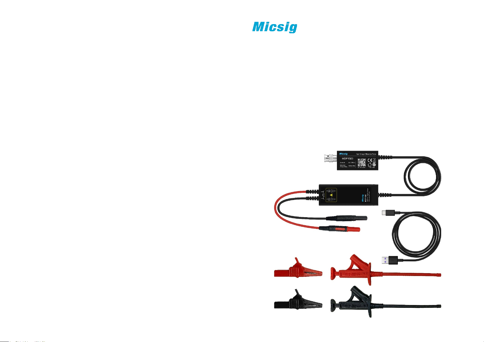
High Voltage Differential Probe -- MDP series
Bandwidth: 100MHz / 150MHz / 200MHz
1. Overview
Originated from Micsig’s cutting-edge SigOFITTM technology, the MDP series high-
voltage differential probe has very low noise floor, excellent amplitude-frequency
characteristics and industry-leading common mode rejection capability, allow users
to test high-frequency and high-voltage signals with ease.
Shenzhen Micsig Technology Co., Ltd.
Tel: +86-755-88600880 Email: [email protected]
Add: A106, Huafeng Robot Industrial Park, Hangcheng Rd, Bao’an, Shenzhen,
Guangdong, China, 518126
Page 2
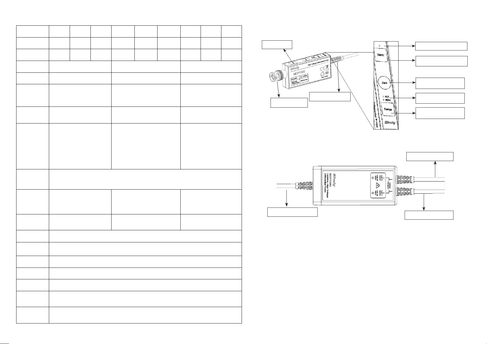
2. Characteristics
Model
Bandwidth
Rise time
Attenuation
20X / 200X
50X / 500X
100X / 1000X
Accuracy
±2%
±2%
±2%
Differential
Voltage
(DC+AC PK)
70V(20X)
700V(200X)
150V(50X)
1500V(500X)
300V(100X)
3000V(1000X)
Max.
Voltage to
ground
CAT I 600V
CAT II 450V
CAT II 1000V
CAT III 600V
CAT III 1000V
Noise
Full Bandwidth:
5MHz bandwidth limit:
Full Bandwidth:
5MHz bandwidth limit:
Full Bandwidth:
5MHz bandwidth limit:
CMRR
DC: >-80dB; 100kHz: >-60dB
10MHz: >-30dB;100MHz: >-26dB
Input
impedance
16MΩ/1.5pF(differential)
8MΩ/3pF(each input to
ground)
16MΩ/1.5pF(differential)
8MΩ/3pF(each input to
ground)
20MΩ/1.5pF(differential)
10MΩ/3pF(each input to
ground)
Delay
Output
voltage
≤3V
Power
supply
Overrange
LED flashes, Buzzer beeps
Dimensions
Control module: L*W*H: 91 *33 *15 /mm
Signal box: L*W*H:100 * 36 * 20 /mm
Cable length
Approx. 8 cm (Input); Approx. 120cm (Output)
Temperature
Operating: 0℃ ~ 40 ℃
Non-operating: -30 ℃ ~ 70 ℃
Humidity
Operating: 5 ~ 85% RH ( 0℃ ~ 40 ℃)
Non-operating: 5% ~ 85% RH (≤40 ℃) ; 5% ~ 45% RH (40 ℃ ~70 ℃)
Cable to signal box
BNC signal output
5MHz Bandwidth Limit Button
Button Panel
5MHz Limit LED Indicator
Signal input:Positive
Cable to Control Module
Signal input:Negative
MDP700
100MHz 150MHz 200MHz 100MHz 150MHz 200MHz 100MHz 150MHz 200MHz
MDP701
MDP702 MDP1500 MDP1501 MDP1502 MDP3000 MDP3001 MDP3002
3. Panel Description
⚫ Control Module
Max. input
≤3.5ns ≤2.33ns ≤1.75ns ≤3.5ns ≤2.33ns
20X: ≤ 22mVrms
200X: ≤ 80mVrms
20X: ≤ 8mVrms
200X: ≤ 70mVrms
11.99ns(20X)
12.27ns(200X)
50X: ≤ 45mVrms
500X: ≤ 200mVrms
50X: ≤ 20mVrms
500X: ≤ 175mVrms
11.99ns(50X)
12.27ns(500X)
USB Type-C
≤1.75ns ≤3.5ns
100X: ≤ 90mVrms
1000X: ≤ 400mVrms
100X: ≤ 40mVrms
1000X: ≤ 350mVrms
11.99ns(100X)
12.27ns(1000X)
≤2.33ns ≤1.75ns
Auto Zero Button
Range LED Indicator
Range Selection Button
⚫ Signal Box
4. Precautions
1) Calibrate the probe before use:
Short-circuit the input ends, power on, press “Zero” button, 5MHz LED light
flashes, after hearing a “Di” sound, means calibration succeeded; if hearing “Di
Di Di” sound, means calibration failed, needs to be calibrated again;
2) The bandwidth of the oscilloscope should be no less than the bandwidth of
the probe, channel input impedance should be 1MΩ.
3) Recommend to use after 10 mins warm-up to get more accurate result.
4) When Range LED indicator flashes and beeps rapidly, indicating Over-
voltage warning, please switch to higher range.
 Loading...