

Page 1
Version: 03/2016
HEAT
PUMP
for swimming pool water
heating & cooling
HP 1100 COMPACT PREMIUM
HP 1500 COMPACT PREMIUM
Installation and user manual
Page 2

Installation and user manual HP1100/1500 COMPACT PREMIUM
Version: 01 /2018 Page 2 /28
HEAT PUMP MICROW ELL HP
Thank you for purchasing Microwell swimming pool heat pump.
Before you use this device, it is necessary to carefully read the entire
Installation and user manual. It is not allowed to commence the heat
pump installation or operation unless full content of this Installation
and user manual is understood and acknowledged. Please keep the
Installation and user manual available in the case of any future
reference is required. Please provide this information also to each
user of the device. Please mind local regulations in your country
regarding installation and usage of this heat pump which are valid in
addition to this User manual.
Contents
1. INTRODUCTION ............................................................................................................................... 4
1.1 Product description ................................................................................................................. 4
1.2 Package checking ..................................................................................................................... 5
1.3 Waste disposal information .................................................................................................... 5
2. SAFETY MEASURES .......................................................................................................................... 6
2.1 Electrical safety ........................................................................................................................ 6
2.2 Usage precautions ................................................................................................................... 6
2.3 Handling precautions .............................................................................................................. 7
3. TECHNICAL SPECIFICATION ............................................................................................................. 8
3.1 Technical data .......................................................................................................................... 8
3.2 Swimming pool water parameters .......................................................................................... 8
3.3 Heat pump dimensions ........................................................................................................... 9
3.4 Description of the basic parts .................................................................................................. 9
3.5 Security and control systems ................................................................................................ 10
3.6 Block wiring diagram of the PCB board ................................................................................. 11
4. HEAT PUMP INSTALLATION AND CONNECTION ............................................................................ 12
4.1 Positioning ............................................................................................................................. 12
4.2 Connection to water filtration circuit .................................................................................... 13
4.3 Needed components for connection to water circuit ........................................................... 14
4.4 Electric connection ................................................................................................................ 16
4.5 Multiple heat pump connection ............................................................................................ 16
4.6 Control of the circulation pump ............................................................................................ 17
4.7 Separate water circuit ........................................................................................................... 18
4.8 Circulation pump connection ................................................................................................ 18
5. REGULATION .................................................................................................................................. 19
Page 3

HP1100/1500COMPACT PREMIUM Installation and user manual
Page 3 /28 Version:01 /2018
HEAT PUMP MICROWEL L HP
5.1 Description of the LCD panel ................................................................................................. 19
5.2 General heat pump control ................................................................................................... 20
5.3 Heat pump operational modes ............................................................................................. 21
5.4 Timer ..................................................................................................................................... 21
5.5 Child lock ............................................................................................................................... 22
5.6 Parameters check .................................................................................................................. 22
5.7 Setting of the operating parameters ..................................................................................... 23
6. ACCESSORIES ................................................................................................................................. 24
6.1 Winter module ...................................................................................................................... 24
6.2 Heat exchanger frost protection ........................................................................................... 24
6.3 Condensate tray defrost ........................................................................................................ 25
6.4 Protection cover .................................................................................................................... 25
7. HINTS AND TIPS ............................................................................................................................. 25
7.1 Water condensation .............................................................................................................. 25
7.2 Defrosting .............................................................................................................................. 26
7.3 Winterizing ............................................................................................................................ 26
7.4 Heat pump season start ........................................................................................................ 27
7.5 Failure reports ....................................................................................................................... 28
7.6 Troubleshooting – save time and money .............................................................................. 30
8. MAINTANANCE & WARRANTY ...................................................................................................... 31
8.1 Maintanance .......................................................................................................................... 31
8.2 Warranty ................................................................................................................................ 32
Page 4

Installation and user manual HP1100/1500 COMPACT PREMIUM
Version: 01 /2018 Page 4 /28
HEAT PUMP MICROW ELL HP
1. INTRODUCTION
In your hands you hold probably the most advanced and the most efficient heat pump currently
available on the market. This heat pump p rovides warm water in your pool at lowest possible cost.
The heat pump is manufactured in tightest accordance with related strict standards and norms, in
order to provide high quality operatio n and long-term reliability.
This Installation and user manual contains all the necessary information about the installation,
operation and maintenance of the heat pump. Please read this Installation and user ma nual carefully
before you start to use this product. The m anufa cturer is not responsible for any p ersonal or property
damage due to the improper installation, use or maintenance that is not in acco rdance with t his User
Manual.
This Installation and user manual is an inseparable p art of this product; therefore it must be kept in
good condition and must accompany the heat pump.
1.1 Product description
The heat pump is designed exclusi vely for swimm ing pool wa ter heating or cooling and maintaining its
temperature on the requested level. Other appropriate application is water temperature conditio ning
for fish tanks, wine ciders or horse cooling facilities. These applications should be discussed with local
installer or distributor. Any other form of application is considered inappropriate.
The heat pump achieves the highest efficiency at 15÷35°C air temperature. At ambient air
temperatures lo wer than -5°C the ef ficiency of the device decreases and at the temperatures higher
than +40°C the heat pump can get overheated which may result in its malfunction, damage or failure.
Do not use the prod uct out of the designated operational air temperature range which is stated
in
section 3.1 Technical data
.
This heat pump is designed for swimming pools with up to 40 m
3
- HP 1100 and up to 60 m3 - HP
1500 of pool water volume . For proper operations there must be water flow through the ex change r of
the heat pump (within water filtration circuit) in the range of 4-6 m
3
/h.
The heat pump enables heat gain from the external air surrounding the swimming pool t hrough the
compression – expansion cycles of the heat-carrying liquid. The air is driven by a fan through the
evaporator where it will deliver it s heat to the heat -carrying liquid (the air is being cooled at the sam e
time). The heat-carrying liquid is then delivered to t he spirals of the exchanger by the compress or
which pressurises it and thus he ats it up. In these spirals, the hea t-carrying liquid delivers its heat to
the swimming pool water. From the exchanger there is a cooled liquid flowing to the expansion valve
or capillary where its pressure decreases and it gets cooled down rapidly at the same time. This
cooled liquid flows to the evaporator again where it gets heated by the flowing air. The whole process
runs fully automatically and is monitored by the pressure and temperature sensors. The same
principle is applied when heat pump operates in cooling mode.
Using simple language, a heat pump is able to extract the heat/cold that is present in ambient
environment and leveraged pass it into the pool water. When heating, higher the ambient air
temperature is, more free energy can the heat pump extract and thus reach higher efficiency. At
favourable conditions you pay around 15% of heat, i.e. 85% of heat is free. Please review below
drawing of different ambient air conditions with subsequent efficiencies.
The heat pump efficiency grows by the increasing surrounding air temperature.
It takes some days to achieve the requested swimming pool water temperature. This time period
depends on heat loss and heat gain ba lance of your pool.
Example factors of heat losses: poor pool construction, used materials, usage of cover, air – water
temperature relationship, fresh water refilling, filtra tion, etc.
Example factors of heat gains: intensity of sun, winds, orientation of pool, air – water temperature
relationship, etc.
In order to avoid heat loss when the swimming pool is not being used, it is highly advised to use
pool’s cover.
Page 5

HP1100/1500COMPACT PREMIUM Installation and user manual
Page 5 /28 Version:01 /2018
HEAT PUMP MICROWEL L HP
Ideal water temperature for external pools is considered at levels from 27° to 32°C. This may change
based on particular demands of the user. When setting the desired air temperature higher than 32°C
please review the material characteristics of your pool parts. High water temperature can damage
these materials a nd contrib ute to creation of algea. Manufa cturer, distributor and reseller do not bear
responsibility resulting from inappropriate heat pump usage.
1.2 Package checking
The unit was delivered in carton box on a wooden palette. Do not accept the package if it shows
signs of damage. If the package appears intact, please unpack the unit and check the content. It
should include the following:
1. The heat pump – one compact piece. Please check section 3.4 Decription of the basic parts to see
how the heat pump looks like
2. This Installation and user manual
3. Four rubber silent blocks
1.3 Waste disposal information
When using this heat pump in the European countries, the following information must be
followed:
DISPOSAL:
Do not dispose this product as unsorted municipal waste. It is prohibited to
dispose this heat pump in domestic / household waste. It is prohibited to dispose this
appliance into forests or natural landscape. This could lead into local soil pollution.
Collection of such waste must be treated individually.
1. The municipality has established a collection system where electronic waste can be disposed.
DISPOSAL POSSIBILITIES:
2. When buying a new product, the retailer or the manufacturer may take back the
old appliance free of charge.
3. Old appliance may contain valuable resources which could be sold to scrap
material dealers.
4. Disposal of packaging materials such as carton box or plastic / bubble foil can be
recycled.
Page 6
Installation and user manual HP1100/1500 COMPACT PREMIUM
Version: 01 /2018 Page 6 /28
HEAT PUMP MICROW ELL HP
2. SAFETY MEASURES
It is necessary to follow instructions in this Installation and user manual and local regulations in
your country that regulate the installation and usage of this device. Incorrect, improper or
operations contradictory to this Installation and user manual may lead to an injury or property
damage and will lead to loss of warranty. To prevent injury or property damage the following
instructions must be followed:
2.1 Electrical safety
• The device operates at dangerous electrical current.
• Only authorized person with particular electro-technical qualification can manipulate with unit.
• Danger of electrical shock.
• Do not exceed the required power supply.
• Do not turn the device on that shows signs of possible damage such as broken packaging, broken or
otherwise damaged unit’s chassis or cover, smoke, smell, etc.
• It is necessary to use appropriate Residual current circuit breaker (RCD) for connection of the heat
pump to main power supply.
• Do not manipulate with the device with wet hands.
• Do not clean the device with water.
• Before cleaning the device, switch off the circuit breaker of the unit’s power supply.
• Installation, service or repair must be performed by qualified technician.
• When the device is not intended to be used for a longer time, we recommend switching the circuit
breaker of the unit’s power supply off.
• Unit must be installed in vertical position to avoid condensate water to enter electrical part of the
unit.
• It is forbidden to install the unit close to devices that may cause electrical or frequency disturbance
such as welding machines, motors or rotors, WIFI/WLAN routers or repeaters.
• It is forbidden to alter electrical installation of the device. It is also forbidden to alter any other part
or functionality of the device.
2.2 Usage precautions
Do not cover or block the intake or exhaust opening / ventilator and evaporator covers. It
is forbidden to block or cover the intake or exhaust openings with clothes, towels,
buckets, canoes, trees, etc. Such action would lead to a decrease of needed airflow. That
would result in heat pump inefficiency and underperformance, eventually to heat pump
overeat with subsequent security turning off, malfunction, failure or damage. Especially
during bloom months it is highly advised to keep the evaporator fins clean.
• Do not climb up on or sit on the unit.
• Do not place any objects on the top of the unit (e.g. boxes, flower vases, etc.).
• Do not spray any flammable substances into the equipment; this might lead to fire.
•
Do not clean the equipment with aggressive cleaning agents, this might lead to damage or
deformations.
• When cleaning plastic parts do not use any cleaning agents unsuitable for plastic (household
cleaning agents, solvents, bleaching agents, benzene, d
iluents, rough cleaning powder, cresol,
chemical agents). Instead, sweep the heat pump cover with a soft cloth or a sponge.
• Never throw or insert any objects into any hose or opening.
• The cover is made of metal. Do not manipulate with lighted cigarette, cigarette ashes, or any other
kind of fire in vicinity to this part.
•
Use this device exclusively for the intended purpose, as described in the attached instruction
manual. Do not use parts which are not recommended.
• Never block the air opening of the product. Protect the air openings from clogging by particles.
•
Do not drink or use the condensate water drained from the unit. Do not return the water back to the
Page 7

HP1100/1500COMPACT PREMIUM Installation and user manual
Page 7 /28 Version:01 /2018
HEAT PUMP MICROWEL L HP
swimming pool. The water may be contaminated with bacteria.
• Children are not allowed to operate, touch or play with the unit.
• Children are not allowed to manipulate with packaging, plastic / bubble foil. Risk of suffocation!
• Prevent the children from injury or harm caused by any manipulation with the unit, its parts or its
packaging. Small parts like screws may be swallowed and cause harm to health.
• Do not leave the children in the swimming pool / at the swimming pool unattended.
• The positioning of the heat pump must be in accordance with the STN 33 2000-7-702 standard, i.e.
it must be placed at least 3,5 m from the swimming pool´s external border.
• For heating/cooling the swimming pool by the heat pump, the filtration pump must run and the
water must flow through the heat exchanger.
• Never turn on the heat pump if it is without water and if the filtration device is not operating.
•
Protect the heat pump from freezing. Eliminate the water from the filtration and from the heat
pump’s water heat exchanger and prepare the product for the winter time.
• At low surrounding ambient temperature level (below 10°C) and high relative air humidity level (e.g.
after rain, during the night, etc.), the evaporator may get iced up. Heat pump will automatically
defreeze itself. Its operations or functionality is not harmed but the efficiency decreases.
• Manufacturer does not bear any responsibility concerning damages caused by inappropriate heat
pump performance and/or model selection, installation or application. Heat pump is considered
undersized in the case it works usually and in long-term more than 18 hours daily. General warranty
void applies for damages on the device or other damages if the device works usually in long-term
more than 18 hours daily.
• The heat pump must be correctly sized for its application.
• Do not pressurize the water heat exchanger higher than 0.15MPa (1.5bar). By pressure of 0.2MPa
(2bar) the water heat exchanger gets irreversibly damaged. It is advised to install a security valve
with pressure threshold at 0.15MPa (1.5Bar) before the heat exchanger.
• Do not apply or use water of higher temperature than 40°C in water heat exchanger. Water
temperature above 45°C irreversibly damages the water heat exchanger.
2.3 Handling precautions
• Leave the unit in vertical upright position for at least 2 hours before the installation.
• Transport in lying position or turning the device over may harm the compressor resulting in unit’s
malfunction, failure or damage and will lead to loss of warranty.
• The device must be handled with care and special attention avoiding any mechanical damage.
• It is forbidden to apply any improper mechanical force onto the unit. This may cause mechanical
damage to the device.
•
It is forbidden to let the device fall freely onto the ground or any solid surface resulting in hard
impact.
• Please notify your reseller or distributor if you suspect that the unit was delivered damaged. Unit
may seem to work well at start but small damage can make the unit go out-of-order in short time.
In such case the unit must be inspected and approved for further use by your reseller.
• Please notify your reseller o
r distributor if directly after installation you suspect that unit is not
working in perfect order.
•
In the case of device failure resulting from improper handling or mechanical damage (impact, hit,
fall, etc.), the manufacturer reserves the right to evaluate the continuity of warranty.
Page 8

Installation and user manual HP1100/1500 COMPACT PREMIUM
Version: 01 /2018 Page 8 /28
HEAT PUMP MICROW ELL HP
3. TECHNICAL SPECIFICATION
3.1 Technical data
HP 1100 COMPACT
PREMIUM
HP 1500 COMPACT
PREMIUM
Air temperature/water temperature
25°C/10°C
25°C/20°C
25°C/10°C
25°C/20°C
Heating output (kW) 10.06 9.55 13.01 12.28
Power consumption (kW)
1.49
1.51
1.92
1.95
Coefficient of Performance (C.O.P.)
6,7
6.3
6.7
6.3
Recommended swimming pool volume (m3) (with
a cover/without a cover)
40/30 60/40
Energy class A A
Operating temperature – air (°C)
-5 (-15)**... +40
-5 (-15)**... +40
Optional swimming pool water temperature range (°C)
+5...+40
+5...+40
Air flow (m3/h)
2520
2520
Recommended water flow (m3/h)/pressure loss (kPa)
4-6/1-5
4-6/1-5
Feeding voltage/Protection (V/A) 230 / 20A/C 230/ 20A/C
Current-carrying capacity/max. current (A) 7/9 9/10
Coverage/Protection
IP X4/by grounding
IP X4/by grounding
Heat exchanger
Titanium
Titanium
Acoustic pressure level dB (A) 1m/2m/4m/8m
54/48/42/36
55/49/43/37
Water circuit connection (mm/inch, thread) 50/ 6/4“ internal 50/ 6/4“ internal
Max. recommended water pipe length (m)
30
30
Max. operational water pressure
0.15MPa (1.5bar)
0.15MPa (1.5bar)
Net unit dimensions (w/h/d)
870/950/320
870/950/320
Gross unit dimensions (w/h/d)
1020/1080/450
1020/1080/450
Net/Gross weight (kg) 67/73 69/75
Refrigerant/filling weight (type/kg)
R410A/1,25
R410A/1,60
* The manufacturer reserves the right to change the parameters without notice.
** In the case Winter module, condensate tray antifreeze or heat exchanger frost protection is installed.
The refrigerant circuit is filled with R410A refrigerant that consists of 2 components (R32/R125).
These components are considered as fluorocarbon greenhouse gases. The product contains
fluorocarbon greenhouse gases listed in the Kyoto Protocol:
R410A with the global warning potential (GWP) 1720 (R-32/125 50/50) CH2F2 + CF3CHF2.
3.2 Swimming pool water parameters
The heat pump is designed for heating the swimming p ool water. Although the water heat exchanger
is made from the most durable titanium, in order to ensure long term reliability of the heat pump the
pool water must be in accordance with the related sanitary requirements.
The limit values for the heat pump operation are the following:
- pH val ue ranging from 6.8 to 7.9,
- total chlorine amount not exceeding 3 mg/l,
- salt content 6% wt/wt.
Should you have different values of pH, chlorine or salt please try to apply appropriate agents or
contact your swimming pool builder to resolve the situation. Above mentioned values are
recommended for pools in general.
Page 9
HP1100/1500COMPACT PREMIUM Installation and user manual
Page 9 /28 Version:01 /2018
HEAT PUMP MICROWEL L HP
It is also advised to keep the water hardness on the lower limit of the optimal range, i.e. closely above
8 °N.
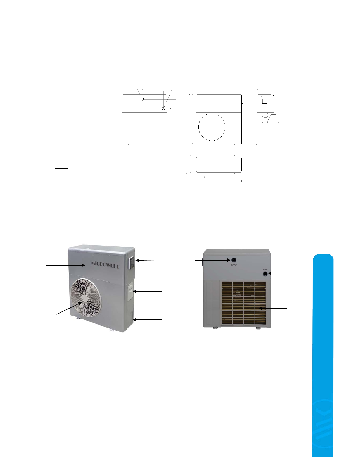
3.3 Heat pump dimensions
3.4 Description of the basic parts
Legend: 1
– Protecting grates of the fan (air outlet) / ventilator cover
2 – Cover / metal chassis
3 – Control panel
4 – Valve for refilling the refrigerant (under the cover)
5 – Power supply connection (underneat h the cover)
6 – Water outlet connection hub
7 – Water inlet conne ction hub
8 – Evaporator (air inlet)
Note: The illustr atio ns an d des cr iptio ns fou nd
in this Installatio n and user manual are not
binding. The manufacturer reserves the right
to make corrections or changes without
notice.
2
1 3 5
4
6 7 8
Power supplz
230V/50Hz
695
965
940
425
875
320
360
546
875
Water outlet
6/4“ internal d 50mm
Water inlet
6/4“ internal d 50mm
Control display
Page 10

Installation and user manual HP1100/1500 COMPACT PREMIUM
Version: 01 /2018 Page 10/28
HEAT PUMP MICROW ELL HP
3.5 Security and control systems
In order to ensure long term reliability and fully automatic operations of the heat pump, the pump is
pump is equipped with following security systems:
Temperature based control of the heat pump operation:
The heat sensor placed on t he heat exchange r, ensures sw itching off of the heat pump when
the requested water temperature is reached. The normal operating mode gets renewed if the
water temperature in the exchanger drops by 3 °C (manufacturing setting) below the
requested value.
Safety systems:
Water flow sensor (flow switch) placed on the water heat e xchanger inlet.
The water flow sens or switches on the hea t pump when there is wate r flowing through the
heat pump exchanger, and switches it off when the water flow stops or is too high or low.
Sensor of the minimal and maximal gas pressure in the refrigerant circuit.
Heat sensor on the refrigerant outlet from the compressor.
Time protection
The unit is equipped with a switching time delaying device with a preset 3 minutes delay
period for protecting the control elements in the circuit and eliminating repeated restarts and
contactor vibrations. This time delay will automatically restart the unit app. 3 minutes after
every single interruption of t he heat pum p operati on. Even if there i s only a sh ort inte rruption
of the power supply, the time protection will get activated so the unit cannot start the
operation earlier t han the pressure s in the refrigerant circ uit of the heat p ump get balanced.
Interruption of the power supply during the pause time does not influence t he time interval.
Antifreeze protection
If an ambient air temperature is low (e.g. below 7°C), it is normal to have ice creations on the
evaporator of your heat pump. This is freezing condensated water. Your heat pump is
equipped with automatic defrosting.
Manufacturer has preset the conditions when automatic defrosting gets activated in order to
ensure optimal operations and performance of the heat pump. For more information please
refer to section 5.7 Setting of the operating parameters
and
section 7.2 Defrosting
.
If your heat pump freezes up on often basis it is advised to reconsider the efficiency of heat
pump running (heating) in such conditions.
If a failure occurs to any of above systems there will be an error message shown on the display
starting with ‘EE’. Please check
section
7.5
Failure reports
of this Installation and user manual.
Warning:
Elimination or disabling from operation any of the control or security systems results in
warranty void.
Page 11

HP1100/1500COMPACT PREMIUM Installation and user manual
Page 11/28 Version:01 /2018
HEAT PUMP MICROWEL L HP
3.6 Block wiring diagram of the PCB board
Legend:
FM – Fan motor
CM - Compressor
OUT 1 – Compressor L
OUT 2 – Compressor N
OUT 3 – output of 4-w ay valve L
OUT 4 – output of 4-w ay valve
OUT 5 - fan L
OUT 6 – circulation pump L
Sensors:
T1 – Evaporator / defrosting
T2 – Inlet water temperature
T3 – Ambient air temperature
T4 – Compressor discharge temperature
T5 – Outlet water temperature
FM
CM
Fan
Compressor
4-way
valve
OUT3 4 5 6 7
PCB board
OUT2
OUT1
CN4
CN6
CN7
CN2
Water flow sensor /
Flow switch
Connector
A, B, C
Transformer
Display
L N 3 4
Compressor
capacitor
Fan
capacitor
Sensors
T5
T4
T3
T2
T1
Heat pump power
supply
L N
Circulation pump
connection
230VAC
max. 500W
Picture: Power supply connection of the heat pump and of the
auxiliary circulation pump.
Notice: Manufacturer reserves the right to change electrical wiring
without notice.
Page 12

Installation and user manual HP1100/1500 COMPACT PREMIUM
Version: 01 /2018 Page 12/28
HEAT PUMP MICROW ELL HP
4. HEAT PUMP INSTALLATION AND CONNECTION
4.1 Positioning
The heat pump is designed for outdoor installation. It must be installed on a stable and levelled base.
The pump can be installed in vertical position only.
a)
The heat pump should be installed in spaces where it can have
sufficient supply of fresh ambient air.
Do not install the heat
pump in closed s paces with li mited air ac cess and where
the air cannot circulate sufficiently. The air inlet and outlet
must be completely accessible. The heat pump should have
minimal distances from surrounding object s as show n on picture
on the right. Do not put the heat pump near bushes or trees
either, as these can also influence the air access. E very single
barrier of free air flow reduces the ef ficiency of the he at
pump and may lead to heat pump’s malfunction, damage or
failure.
b) Although the heat pump is designed for exterior installation (sunlight, rain, snow) it is
suggested to make a shelter / roof in order to protect its metal parts and thus ensure long term
stability of color, metal chassis, etc.
c) Do not install the device near road networks, as increased concentration of dust gradually
decreases the heat exchange effectiveness.
d) When hea t pump is in f ull heating oper ation, it ge nerates conside rably colde r air than ambi ent
air temperature. It is thus advised not to in stall the heat pump at places, where cold air flow
could cause any inconvenience (windows, terraces, etc.). Also, do not place the air outlet
against the dominant winds.
e) The distance between the swimming pool edge and the hea t pump should not exceed 30 m.
Please note that the longer interconnecting water piping is, the higher heat loss occurs, i.e.
lower heating output and less ef ficiency is achieved. Practically t his results in longer heating
times and higher electricity bill. It is not advised to install the heat pump very close to
swimming pool water surface.
f) The heat pump must be placed on a flat, stable and levelled surface. The pum p housing must
be fixed to this surface with screws and rubber anti-vibration elements ( silent blocks). Rubber
anti-vibration elements not only reduce the noise level of the heat pump, but also help to
eliminate the vibra tions and thus they cont ribute to smoother hea t pump operations and long
term reliability.Please note t hat heat pum p should be i nstalled above the closest t errain level to
allow the condensation water leak out of the heat pump. Please refer to
section 7.1 Water
condensation
.
g) The surface of the evaporator consists of aluminum fins. The fins are soft and can get
mechanically damaged very easily. Please be careful when manip ulating with th e unit to avoid
any damage.
h) It is advised to install the heat pump on a stand 300-500mm above surrou nding ground
in the case the heat pump is to operate in low ambient air temperatures. Heat pump installed
directly on a surrounding ground can by easily immersed into snow and/or into frozen
condensation. This can decrease heat pump’s efficiency and performance and lead to heat
pump malfunction, damage or failure.
Notice: Please discuss particular details of heat pump positioning and connection to the swimming
pool water circuit with your swimming pool builder, distributor or reseller!
Picture: Minimal distances from surrounding
objects.
Page 13

HP1100/1500COMPACT PREMIUM Installation and user manual
Page 13/28 Version:01 /2018
HEAT PUMP MICROWEL L HP
4.2 Connection to water filtration circuit
The heat pump must be connected to water circuit (filtration circuit) of the swimming pool in order to
provide desired heating/cooling performance. The water flow through the exchanger of the heat pump
must be in accorda nce with the designed value (
see chapter 3.1 Technical data
). Normally the heat
pump is connected through a by-pass. It is then possible to adjust the water flow accordingly as
filtration pumps may have different water flow performances.
The by-pass consists of 3 valves connected as shown in the picture below. Wa ter normally flows from
the filtration pump (right side) to the swimming pool (left side) through Valve 1. Heat pump is
connected through Valve 2 (heat pump inlet) and Valve 3 (heat pump outlet).
Complete closure of Valves 2 and 3 with Valve 1 fully open means no water flow through the heat
pump which means no heating or cooling provided by the heat pump.
Complete closure of Valve 1 with Valve 2 and 3 fully open means maximum amount of water flowing
through the heat pump.
Normally the by-pass is set as shown on below picture.
The heat pump is eq uipped wit h 2 threads e nabling the conne ction of input and output fitt ing (d50).
For connection wit h the filtration circuit use the d50 PVC pipe or 50/38mm adapters (6/4”). Please
refer
to section 3.4 De scription of the basic parts
in order to m ake sure which t hread is water input
and which water output. It is advised to apply lubricating oil on threads before tightening the
connection.
Please consider using fast connector for the heat pump inlet and outlet in order to make the
disconnection of the heat pump from the rest of the filtration circuit simple (for water draining from
the heat pump before winter time and for service purposes).
The heat pump must be conne cted to the filtrat ion circuit of the sw imming pool b ehind the filter and
in front of the device for water conditioning (automatic chlorine dozing machine, ozone machine).
For illustration please refer to Scheme: Connection of the compact heat pump into the water
filtration circuit of the swimming pool on page 15.
Note: In case of using the automatic chlorine dozing machine in the filtration circuit it is
necessary to install a backward titanium spring in front of it. If this valve is missing, b y shutt ing
down the filtration, the chlorine concentration around the heat pump exchanger may be
increased to critical level and exceed the allowable level (3 ppm) causing damages.
Back to the swimming
pool
From the filtration
pump / swimming
pool
Connection of the by-pass
VALVE
VALVE
VALVE
To the heat pump
From the heat pump
Page 14

Installation and user manual HP1100/1500 COMPACT PREMIUM
Version: 01 /2018 Page 14/28
HEAT PUMP MICROW ELL HP
4.3 Needed components for connection to water circuit
It is advised to use hose nut with external thread PN16 50 x 6/4” and a pressure hose D50 or PVC
pipe D50.
Particular component selection depends on individual condition at your pool. Your seller,
distributor or pool builder may decide on how the actual connection is performed. These
components are not part of heat pump package or delivery.
Sample connection scheme and application example
Important: For proper operations, there must be a water flow through the heat pump
exchanger in range of 4-6 m
3
/hour. In the case of water flow exceeding 10m3/h the
heat pump will turn itself off and an error notice EE5 will pop up. Repeated error
notice or repeated exposure of the heat pump to the wat er flow higher than 8m
3
/h
will cause irreversible damage to flow switch wit h permanent error notice EE5. The
heat pump will be turned off. Please contact your distributor or service department,
the flow switch needs to be replaced.
Picture: Pressure hose
D50
Error code ‚EE5‘ advising of low / high water
flow or damaged flow switch.
Picture: Hose nut with external thread PN16.
G=6/4” D=50mm
Picture: PVC pipe, various
dimesions
Picture: Sample water connection to the heat pump. Flexible hose glued
onto hose nut adapter with external thred that is tightened into the heat
pump exchanger thread.
Page 15

HP1100/1500COMPACT PREMIUM Installation and user manual
Page 15/28 Version:01 /2018
HEAT PUMP MICROWEL L HP
Scheme: Connecti on of t he compact heat pump into the water filtration circuit of the
swimming pool
Note:
WALL
(fence,
house)
The manufacturer su pplies the heat pump only. The other parts and components shown in the
picture are not included in heat pump package.
HEAT PUMP
Water outlet
Water inlet
Air suction
Exhaust air
By-pass valves
Skimmer
SWIMMING POOL
TECHNOLOGICAL
CHAMBER
Water supply from
water mains
Water discharge
Condensate drain
Filtration tank
Filtration valve
Filtration pump
Bottom outlet
Reversible
nozzle
Chlorine dozing
machine
Page 16

Installation and user manual HP1100/1500 COMPACT PREMIUM
Version: 01 /2018 Page 16/28
HEAT PUMP MICROW ELL HP
4.4 Electrical connection
IMPORTANT: The electric connection of the heat pump can only be
performed by an authorized electrician in accordance with local electrical
standards and requirements.
WARNING: The device operates at dangerous electrical current and
voltage.
DANGER: Danger of electric shock!
a) The heat pump must be connected through a single circuit-breaker specified
in section 3.1
Technical data
for a particular model. The dimensioning o f the power supply must be sufficient
(the suggested cross section of the conductors is 3 x 2,5 mm
2
). It is important to make sure and it
is nonconditionned r equirement of the m anufacturer to instal l the heat pump tog ether with RCD
(Residual Circuit Breaker) with the actuating current up to 30mA. The power supply
characteristics (voltage, phase and fre quency) m ust be in complete compliance with the operat ing
parameters of the device (please refer
to section 3.1 Technical data
).
b) The electri c co nnection must be performed by an authorized electrician and must be in accord anc e
with the valid local electro-technical requirements.
c) The electric installation of the heat pump must be grounded appropriately. The grounding
distributor´s impedance must be in compliance with local valid electro-technical requirements.
d) The electro connection of the heat pum p must be simple, clear and comprehensible. It is highly
advised to have the connection performed in a way that would allow a third party electrician to
understand the connection at no time. Unnecessary cross connections are not appropriate.
e) It is important to carefully check and measure the electric installation before putting it into live
operation.
f)
The suggested protection is stated in the chart below:
Heat pump model
HP 1100
HP 1500
RCD parameters
Current-carrying
capacity
16 A/C 20 A/C
Actuating current
30 mA 30 mA
Circuit breaker characteristic
16 A/C 20 A/C
g)
Block wiring diagram is included
in section 3.6 Block wiring diagram of the PCB board
.
h) In order to protect the unit from weather anomalies it is recommended to install power surge
protection class 1. B+C+D.
Note: Should above points a) to h) be in contrary with local electrical standards or requirements,
please contact your distributor or reseller.
4.5 Multiple heat pump connection
Sometimes it is necessary to install multiple heat pumps into a single swimming pool in order a chieve
requested water temperature. Such installation is particularly advised on public venues where
continuity of operation / service is paramount.
Installation of the multiple heat pumps follows t he same procedure as single heat pump described
above. It is only necessary to install the heat pump s in pa rallel connection. Ser ia l connection w ould
significantly decrease the heating/cooling capacit y and efficiency of heat pumps second in line. It is
advised to insert individual valves into connecting water piping for each single heat pump. This will
Page 17

HP1100/1500COMPACT PREMIUM Installation and user manual
Page 17/28 Version:01 /2018
HEAT PUMP MICROWEL L HP
simplify the particular heat pump by-pass (disconnection) in the case of reinstallation, testing or
service. Please refer to below illustration.
By multiple heat pump connection it is possible have all the heat pumps always on and running
when heating / cooli ng is require d or to have the he at pumps gra dually turning on and off so at
certain conditions (e.g. when requested water temperature is few degrees off the current water
temperature) not a ll the he at pumps w ould run. Gra dual t urning on and off is ac hieved by s etting the
different requested water temperatures on multiple heat pumps. For example:
Heat pump 1 30°C
Heat pump 2 28°C
4.6 Control of the circulation pump
Microwell swimming pool heat pump is able to control the circ ulation pump. In principle should the
heat pump be in need for heating/cooling it will automatically turn the circulation pump on.
In order to enabl e this con trol, the cir culation p ump must b e connecte d to the heat pump electricall y
(please
refer to section 3.6 Block wiring diagram of the PCB board
). Normally the circulation pump is
controlled by a time control of the filtration. It is thus advised to make the parallel connection
through power relay enabling both sources of regulation (by the heat pump and by the time
control).
Please note that both heat pump and the time control must be
powered by the same single phase!
Please be advised that when circulation pump control is enabled and ele ctrically connected with t he
heat pump, it is normal to have a situation when both the heat pump and the time control give
command to circulation pump to operate at the same time. It is thus stric tly forbidden to power
the heat pump and the time control by different phases!
The control is available in three modes:
1. Periodical mode
Heat pump will turn the circulation pump on only when it needs to heat or cool (i.e. requested water
temperature is off the current temperature by at least 2°C).
Periodical mode can be set in manufact uring se ttings n umber 07, figure 0. (please refer
to section
5.7 Setting of the operating parameters
)
Periodical mode is also equipped with sampling, i.e. re gular wate r tem perat ure reading. Pra cticall y
this means that as soon a s the heat pump reaches r equested temperature it turns itself and the
Heat pump number 1
Heat pump number 2
Swimming pool
Filtration
tank
6-way
valve
Circulation
pump
By-pass for
heat pump
Main by-pass
Page 18

Installation and user manual HP1100/1500 COMPACT PREMIUM
Version: 01 /2018 Page 18/28
HEAT PUMP MICROW ELL HP
circulation pump off. In the case the water temperature will not trigger the heat pump in following
60 minutes, the heat pump will a utomatica lly turnt the circulatio n pump on for a 1 minute time in
order to recirculate water from to the pool into the heat exchanger in order to read the actual
current water temperature.
2. Continous mode
In continuous mode w ill the heat pum p have the circ ulation pump turne d on and running all t he
time the heat pump is in operational mode (please
refer to section 5.2 General heat pump control
for explanation of operational mode).
Continous mode achieves better water temperature readings but means higher energy
consumption of the system as the circulation pump is always on.
Continous mode can be set in manufacturing settings number 07, figure 1. (please refer
to section
5.7 Setting of the operating parameters
)
3. microECONOMY+ Mode
microECONOMY+ mode provides optimum water temperature conditioning at lowest cost. Heat
pump will have t he circulation p ump running only i n time when the heat pump ne eds to heat or
cool the water. Once the requested water temperature is achieved the heat pump goes into sleep
for 30 minutes. After these 30 minutes are passed, the heat pump will have the circulation pump
running for about a minute to receive actual accurate water temperature. Should heating or
cooling be required, t he heat pumps starts. Should no action be required, the heat pump goes
into 30 minute sleep ag ain. This 30 min ute per iod can be cance lled by p ressi ng a ny butto n on the
controller.
microECONOMY+ mode can be set in manufacturing settings number 07, figure 2. (please refer
to
section 5.7 Setting of the operating parameters
)
Please note that all heat pump models may not be equipped with microECONOMY+ mode.
4.7 Separate water circuit
In order to save energy it is possible to install the heat pump on a separate water circuit with small
circulation pump. This is appropriate in the case the power consumption of circulation pump for
filtration is considered high or simply if the whole filtration circuit ru nning is not de sired when he ating
/ cooling is required.
Normally swimming pool circulation pumps with water flow performance betwee n 4-6m
3
/h consume
up to 0.5kW of energy.
Such installation must be discussed with your swimming pool supplier, distributor or reseller.
4.8 Circulation pump connection
Manufacturer sugge sts connection of circulation pump through switchi ng relay. Please refer to below
drawing for more information. Direct connection of the circulation pump is not advised.
HEAT PUMP
Circulation pump
Switching phase 230VAC
Relay 230VAC
Circulation pump power supply
Circulation
pump
Page 19

HP1100/1500COMPACT PREMIUM Installation and user manual
Page 19/28 Version:01 /2018
HEAT PUMP MICROWEL L HP
5. REGULATION
5.1 Description of the LCD panel
Cooling symbol
- Heating symbol (lit
contantly)
- Defrosting (blinking)
AUTO mode symbol
General indication
Screen lock
(displayed when
child lock is applied)
Indication of
manufacturing’s
settings
Current water
temperature
Requested water
temperature
Main power on/off
button.
- Mode change (heating,
cooling, auto mode)
- Operational parameters
setttings
Up / down
selection,
water
temperature
settings
Timer (displayed
when timer is
activated with preset
time-out period)
Timer – heat pump
to turn itself on/off
(displayed when
timer is activated)
Checking of technical
parameters
Forced
defrosting
Water pump modes
indicator
Defrosting (blinking)
Page 20

Installation and user manual HP1100/1500 COMPACT PREMIUM
Version: 01 /2018 Page 20/28
HEAT PUMP MICROW ELL HP
5.2 General heat pump control
After the installation, the heat pump is to be controlled by digital display only. Directly after
installation with still no power supply to your heat pump, the digital controller will be blank. This
means a complete shut down of the heat pump.
When heat pump receives required power supply, for a moment the display will show all its
indications.
After few moments the heat pump will go into STAND-BY mode. This means that the heat pump is off
but it is connected to the mains at the same time. The display will show the mode of the heat pump
(in below picture a triangle that indicates AUTO mode) and the current water temperature, in below
particular case 30°C.
By pressing the m ain power on/off butto n you ca n turn your heat pump on to OPERATIONAL
mode. The display will show the mode of the heat pump (in below picture a triangle that indicates
AUTO mode), requested or desired water temperature on the left, showing 30°C in below picture, and
current water temperature on the right, showing 30°C.
You are able to set the requested water temperature. By pressing the up and down
buttons the requested water temperature increases or decreases by 1°C. You will see immediate
change of desired temperature on the left. The preset water temperature range is +5°C ~ +40°C.
Note: Some heat pump models require confirmation of requested water temperature if
changed. This is done by pressing the main power on/off button .
By pressing the M butt o n you can chan g e the ope ra tional mode of the hea t p ump. Please refer
to
section 5.3 Heat pump operational modes
of this Installation and user manual.
By pressing the main power on/off butt on you can turn your heat pump off.
Picture: Blank display indicates no power supply and
complete shutdown of the heat pump.
Picture: Display showing all its indication for a moment only when
the heat pump receives power supply.
Picture: Stand-by mode.
Picture: Operational mode.
Page 21

HP1100/1500COMPACT PREMIUM Installation and user manual
Page 21/28 Version:01 /2018
HEAT PUMP MICROWEL L HP
5.3 Heat pump operational modes
Auto mode
- display shows a triangle symbol and a description ‘AUTO’. Heat pump automatically keeps the
requested water temperature. This means that heat pump automatically heats or cools when the
difference between water temperature and the requested water temperature is 2 degrees of Celsius.
The temperature difference of 2 degrees o f Celsius is called Hysteresis. It is possible to change this
settings (please
see section 5.7 Setting of the operating parameters
, point 10).
Heating
- display shows a sun symbol. Heat pump only heats the water. This means that the heat
pump turns itself off after a requested water temperature is reached. Heat pump turns itself on again
when the water temperature decreases by 2 degrees of Celsius below the requested water
temperature. The temperature difference of 2 degrees of Celsius is called Hystere sis. It is possible to
change this settings (please
see section 5.7 Setting of the operating parameters
, point 10).
Cooling
- display shows a snow flake symbol. Heat pump turns itself off after a requested water
temperature is reached. Heat pump turns itself on again when the water temperature increases by 2
degrees of Celsius below the requested water temperature. The temperature difference of 2 degrees
of Celsius is called Hysteresis. It is poss ible to change this settings (plea se
see section 5.7 Sett ing of
the operating parameters
, point 10).
Recommendation: Manufacturer recommends heat
pump regulation by AUTO-MODE.
Warning:
5.4 Timer
Manufacturer does not recommend changing of
hysteresis settings. It may be changed by an experienced user only.
It is possible to have your heat pump turned on and/or off automatically by timer function.
Automatic turning on
You can use this f un cti o n w hen you w ould li ke yo ur he a t p ump t ur ned o n afte r some time period. You
set the ‘Timer on’ function in STAND-BY mode (heat pump off and connected to the mains) by
pressing the ‘Clock’ button .
By pressing the buttons, you can set the number of hours after which the heat pump will
automatically turn itself on. The time setting range is 1-24 hours.
To confirm the settings, please no action for few seconds. You will see preset desired number of
hours, clock icon and icon ‘ON’ as shown on below picture.
Picture: Timer set on. Heat pump to
start in 6 hours.
Picture: Timer set on. Heat pump to
turn off in 6 hours.
Page 22

Installation and user manual HP1100/1500 COMPACT PREMIUM
Version: 01 /2018 Page 22/28
HEAT PUMP MICROW ELL HP
Automatic turning off
You can use this functi on when you would like your heat pump turned off after some t ime p eriod. You
set the ‘Timer on’ function in operating mo de (heat pump on) by pressing the ‘Clock’ button .
By pressing the buttons, you can set the number of hours after which the heat pump will
automatically turn itself off. The time setting range is 1-24 hours.
To confirm the settings, please no action for few seconds. You will see preset desired number of
hours, clock icon and icon ‘OFF’ as shown on above picture.
To cancel the timer, press the clock button again and you leave timer settings mode.
5.5 Child lock
Your heat pump controller allows you to lock its settings in order to protect them from undesired
changes. This is mainly used in the case of a risk that children would unintentionally change the
settings of the heat pump.
By pressing and holding both buttons for 5 seconds at t he same time, the child lock gets
activated. In order to disactivate the child lock, please repress and hold the buttons again for 5
seconds.
5.6 Parameters check
During heat pump operations (heating or coo ling) you can read severa l basic technical paramet ers.
This is mainly useful for a service technician.
Following parameters can be checked:
14 – Input water temperature (T2)
(-9°C + 99°C)
15 – Ambient air temperature (T3)
(-9°C + 99°C)
16 – Temperature on the compressor discharge (T4)
(0°C + 159°C / values above 100°C showed
as Axx, e.g. 105°C showed as ‘A05’)
17 – Evaporator temperature (T1)
(-9°C + 99°C)
18 – Output water temperature (T5)
(-9°C + 99°C)
In order to enter the Parameters check reading please press and hold the clock button for 3
seconds during the heat pump’s operational mode. The parameters will be displayed starting with
Picture: Parameters check, input
water temperature 30°C.
Picture: Child lock activated. A lock icon is
showed on the left.
Page 23
HP1100/1500COMPACT PREMIUM Installation and user manual
Page 23/28 Version:01 /2018
HEAT PUMP MICROWEL L HP
parameter ‘14’ (showing at position of requested water temperature – on the left) with particular
measured value, e.g. ‘30’ (showing at position of current water temperature – on the right). For
example 14 30 would mea n that the water tempera ture on the input to the heat pump (swimming
pool output) is 30°C.
Then repress the „clock“ button to display the parameters in sequence (parameters from 14 to 18).
Note: 10 seconds a fter the la st pressing of the button, the display switches o ver to the display of the
operational mode.
5.7 Setting of the operating parameters
It is possible to change pre set technical parameters of your heat pump. Plea se be advised that the
manufacturer has fine -tuned the technical parameters in order to achieve the best possible operations
and efficiency. Thus a change in these settings is not advised.
Should there be a need to change ma nufa ctur i ng se tt ings pl ea se discuss the ma tte r w it h your sel ler or
distributor alternatively with the manufacturer. Change in preset settings may lead into heat pump
undesired performance issues, inefficiency, malfunction, failure or damage. Change can only be
performed by trained technician.
Your heat pump enables settings of 11 operational parameters. Please note that only trained
technician is allowed to perform change in manufacturing preset settings.
In STAND-BY mode (heat pump off) press and hold the „M“ button for 3 seconds. The
parameters will be displayed starting with param eter ‘00’ (showing at position of requested
water temperature – on the left) with particular preset set ting, e.g. ‘ 0’ (showi ng a t position o f
current water temperature – on the right).
Then repress the „M“ button to display the parameters in sequence (parameters from 00 to
11, see the chart below).
The requested value is adjusted by pressing the
and buttons on the particular
parameter.
By keeping the „M“ button pressed for 3 seconds in the operating mode, you can
enter the reading of preset technical parameters, however you cannot change
them. For more information please
see section 5.6 Parameters check
.
Figure Meaning Range Manufacturing setting
00 Setting of the requested max. water
temperature
0/1~45/60°C
0
01 Temperature setting for the beginning
of the defrosting
-20°~10°C
-7°C
02 Temperature setting for the end of the
defrosting
5°~45°C
13°C
03 Setting of the defrosting time period
30 ~150 min.
45 min.
04 Setting of the forced defrosting time
period
1 ~15 min.
3 min.
05 Setting of the compressor´s
protection temperature
70 ~110°C
95°C
06 Temperature for 4-way valve
activation
0 ~60°C
7°C
07 Working mode of the circulation pump
(0 = Periodical / 1 = Continouos / 2 =
microECONOMY+)
0 ~2
2*
08 Restart after power cut
0 ~1
(0-no, 1-yes)
1
Page 24

Installation and user manual HP1100/1500 COMPACT PREMIUM
Version: 01 /2018 Page 24/28
HEAT PUMP MICROW ELL HP
Figure Meaning Range Manufacturing setting
09 Type (0-only heating, 1-
heating+cooling, 2heating+cooling+two exchangers)
0 ~3
1
10 Hysteresis - difference between the
current and requested water
temperature for the regulation startup
1 ~10°C
2°C
11 Sensor T2 correction -10…+10
0
12 Water temperature outlet limit (0 = -
5°C / 1 = +5°C)
0-1
1**
13 Sensor T5 correction -10…+10
0
* - only available at certain heat pump models. If not available then mode 0 is preset.
** - do not set this setting to “0” unless only a non-freezing liquid instead of water
is circul ated through the heat pump!
Note: The manufacturing settings may differ from the data in the chart.
Note:
6. ACCESSORIES
10 seconds after the last pressing of the button, the display switches over to the standard
display of the requested water temperature/current water temperature (while running), or the
current water temperature in STAND-BY mode.
6.1 Winter module
Winter module has been designed for effective operations of the heat pump at subzero ambient air
temperatures. It heats the lower part of the compressor (oil tank) resulting in higher oil viscosity
which subsequently easies the compressor operations. Winte r module is automatically activated when
the compressor is off and ambient air temperature is below -5°C. After t he heat pump is turne d on,
i.e. after compressor is turned on, winter mod ule turns itself automati cally off. U ser is not required to
perform any action towards heat pump regulation. System works fully automatically. Power
consumption is 45W. In the case the heat pump will not be used in winter time, along with
winterizing, it is suggested to turn the heat p ump’s circuit breaker off in order to avoid unnecessary
energy consumption. Winter module is on demand and is not supplied with each heat pump by
standard.
6.2 Heat exchanger frost protection
Frost protection for heat exchanger ensures protection of the water heat exchanger against rapid
ambient air temperature variation under the subzero temperatures. It is a heating spiral which is
attached onto the heat exchanger body. Heat exchanger frost protection can generally protect the
heat exchanger; however it is not advised to expose the heat exchanger to extremely low
temperatures (e.g. -15°C) for long term with water filtration turned off.
Please be advised that local ambient air temperature around your condensing unit may be lower than
the one measured for example at the external wall of your house. This may be caused by various
factors (for example wind). Please be advised that connection water piping outside of the water heat
exchanger is not protected by the heat exchanger frost protect ion. Heat exchanger frost protection is
automatically regulated. It turns itself on if the ambient air temperature decreases below 2°C. Power
consumption is 64W. In the case the heat pump will not be used in winter time, along with
winterizing, it is suggested to turn the heat pump’s circuit breaker off in order to avoid unecessary
energy consumption. Heat exchanger frost protection is on demand and is not supplied with eac h he at
pump by standard.
Notice: Manufacturer reserves the right to change parametres or controller functions without notice.
Page 25

HP1100/1500COMPACT PREMIUM Installation and user manual
Page 25/28 Version:01 /2018
HEAT PUMP MICROWEL L HP
6.3 Condensate tray defrost
Condensate tray defrost ensures protection of the tra y against frost. This is created in the case the
heat pump works in subzero ambient air temperatures. When heat pump defreezes itself, water drops
are flowing from the evaporator fins into the conden sate tray. In the case, the tray is not equipped
with active defrost , gathered water continuously transforms into ice. In the case the ice reaches the
evaporator, it can cause its damage. Condensate tray defrost is a heating spiral which is attached onto
the tray.
Please be advised that local ambient air temperature around your condensing unit may be lower than
the one measured for example at the external wall of your house. This may be caused by various
factors (for example wind). Please be advised that connection water piping outside of the water heat
exchanger is not protected by the heat exchanger frost protection. Heat exchanger frost protection is
automatically regulated. It turns itself on if the ambient air temperature decreases below 2°C. Power
consumption is 64W. In the case the heat pump will not be used in winter time, along with
winterizing, it is suggested to turn the heat pump’s circuit breaker off in order to avoid unecessary
energy consumption. Co ndensate tray frost protection is on demand and is not supplied with each
heat pump by standard.
6.4 Protection cover
Protection cover /braced up PVC/ is designed for heat pump coverage for a period when the heat
pump is not in operations (it is winterized or water is removed from heat exchanger and the electricity
is disconnected). Prot ection cove r should be p ut onto the hea t pump from abo ve and shoul d be fixed
with a string at the bottom against wind. It is strictly forbidden to turn the heat pump on and operate
it with the protection cover on. This situation would caus e insufficie nt amou nt of air (e nergy) for hea t
pumps operations w hich would lead to almost none performance both by heati ng and cooling. This
situation would almost immediately lead to heat pump overheating which could cause a malfunction,
damage or a complete failure of the heat pump. Warranty does not cover any heat pump damage or
other damage caused by heat pump operations with the protection cover on.
7. HINTS AND TIPS
7.1 Water condensation
It is normal to have water dropping or leaking from the evaporator during heat pump operations,
particularly during heating. During heating, the evapo rator is normally cold. It can easily reach dew
point conditions. Dew point means that at given air temp erature and relative humidity any surface
that is of below dew point temperature condensates the water from surrounding air.
Condensation can result even in liters of water being leaked out of the heat pump. If you suspect a
leak on water circuit, as a first step it is advise d to check if it is condensation. The condesated water
flows over the evaporator lamellas into the casing base. Then flows out through a plastic fitting
designed for connection to the ¾“ PVC tube by which the conde nsate can b e taken to a n appropriate
drain.
1. Turn off the device and leave only the swimming pool pump (circulati on pump ) in operation.
If the water stops to flow out, then it is condensing water.
2. Test, whether there is any chlorine or salt found in the outflowing water (if chlorine or salt are
used). If there is no chlorine or salt, then it is a condensate.
Page 26

Installation and user manual HP1100/1500 COMPACT PREMIUM
Version: 01 /2018 Page 26/28
HEAT PUMP MICROW ELL HP
7.2 Defrosting
As described
in section 3.5 Security and control systems
, your heat pump is equipped with active
defrost protection. Defrost protection has following modes:
1. Normal d efrosting – de frosting gets activated in the case heat pump measures low
temperature of the evaporator (sensor T1) (-7°C). It is possible to change this
setting. Manufacturer has preset the settings for optimal heat pump operations.
2. Cyclical defrosting – this mode gets activated if evaporator temperature sensor
fails (T1). In this situation your heat pump does not have a measured input if
defrosting should be activated or not. Thus in orde r to protect the heat pump it wil l
automatically defreeze itself in 45min intervals.
3. Forced defrosting – this mode can only be activated manually by pressing and
holding button for 5 seconds.
Heat pump signalizes defrosting by blinking the ‘sun’ icon of he ating or .
7.3 Winterizing
Your heat pump continuo usly contains water in its water hea t exchanger. This water will freez e up
and damage irreversibly the heat exchanger if exposed to sub-zero air temperatures, normally during
winter time. It is then necessary to prepare the heat pump for sub-zero air temperatures (e.g. winter
time). Generally, the water from inside the water heat exchanger must be removed. Winterizing is
done on heat pumps which do not ope rate all yea r round. In th e case you operate your heat pump all
year round and/or also in winter months when ambient air temperature decreases below 0°C it is
necessary to ensure continuous water circulation through the water heat exchanger with water of
temperature at least 20°C. In the case this is not done, water inside the water heat exchanger may
cool down and subseque ntly freeze up which cause s destructive damage to heat exchanger and the
heat pump will no longer be operational. Warranty excludes such damage.
Winterizing:
1. Disconnect the heat pump from the mains (e.g. by turning the circuit breaker off).
2. Close the bypass valves number 2 and 3 (Please refer
to section 4.2 Connection to water
filtration circuit
).
3. Make sure tha t the h eat p ump is dis connec ted f rom the mains (elec tricity ). Do not
continue if the heat pump still has power supply or shows signs of it.
4. Unscrew t he hose nut s of both wate r inlet and out let in order to allow air to enter t he water
heat exchanger (please refer
to section 4.3 Needed components for connection to water
circuit
). This will actually allow you to drain water from the heat exchanger.
5. Unscrew the front fixation screws (silent blocks).
6. Bent the heat pump a bit to the back in order to remove as much water as possible from the
heat exchanger. Once the heat pump is bent over (from original 90° angle to approximately
80°) and no water leaks out, you have removed the water. To get graphic visualition please
view below drawings and/or video from below QR code .
90°
app.
80°
Video
Page 27

HP1100/1500COMPACT PREMIUM Installation and user manual
Page 27/28 Version:01 /2018
HEAT PUMP MICROWEL L HP
7. After the water leaked out, please repeat the steps in reversed order from point 5 of this
section.
Please make sure that all water is removed from the heat
exchanger before sub-zero air ambient temperatures period
(e.g. winter time). Damage of the heat exchanger resulting
from frost is excluded from warranty.
7.4 Heat pump season start
After winter time you need t o prepa re your hea t p ump for new sea son. In general please refer to this
Installation and user Manual. Heat pump must be connected to the mains, water circuit; it must
comply with positioning requirements.
During the initial start of the heat pump it is possible to have EE5 error. This sign als low, high or none
water flow and results in heat pump turning off. If your water piping is intact, circulation pump
operates in order; the reason for this initial report may be air bubbles in water system. These tend to
gather around the flo wswitch and thus cause incorrect indication of water flow.
In order to remove the water bubbles from the system you need to bleed the water circuit to remove
any outstanding air.
Position 1: Heat pump in
normal position.
Position 2: Heat pump bent
over for water bleeding.
Page 28

Installation and user manual HP1100/1500 COMPACT PREMIUM
Version: 01 /2018 Page 28/28
HEAT PUMP MICROW ELL HP
7.5 Failure reports
Please find below table containing list of failure reports with their explanation and suggested solutio n.
In order to physically locate the se nsor please refer
to section 3.6 Block wiring diagram of the PCB
board
.
Failure
report
(displayed
on diplay)
Operating status of
the heat pump
Description of the failure
report
Sensor
characteristic
Failure report resolution
EE1
Heat pump
decommissioned;
acoustic warning
Water temperature sensor
failure (T2) / interrupted
or short-circuited sensor
5kΩ
Check the sensor, possibly
change the sensor
EE2
Heat pump
decommissioned
Surrounding air
temperature sensor
failure (T3) / interrupted
or short-circuited sensor
5kΩ
Check the sensor, possibly
change the sensor
EE3
Heat pump
decommissioned;
Acoustic warning
Compressor discharge
sensor failure (T4) /
interrupted or shortcircuited sensor
50kΩ
Check the sensor, possibly
change the sensor
EE4
Optical warning
Timed defrosting
Evaporator temperature
sensor failure (T1) /
interrupted or shortcircuited sensor
5kΩ
Check the sensor, possibly
change the sensor
EE5
Heat pump
decommissioned
in app. 1-2
minutes after
turning on;
acoustic warning
None/Weak/High water
flow; No closure of the
flow switch or failure of
the flow switch
Flow switch
Set the water flow to 4-
6m3/h or check the flow
switch
EE6
Heat pump
decommissioned;
acoustic warning
High temperature on
compressor discharge
(T4)
50kΩ
Please refer
to section 7.6
Troubleshooting
EE7
Optical warning
Electric leakage
protection
-
Check the power supply of
the unit, circuit breaker. In
order to remove EE7 optical
warning, power supply needs
to be turned off and on
EE8
Acoustic warning
Failure of the cable
communication of the
controller
-
Check the control cable
between the control board
and the control digital panel
EE9
Heat pump
decommissioned
High/Low pressure switch
protection
In order to remove EE9
optical warning, power
supply needs to be turned off
and on
-09
Heat pump
decommissioned
Temperature sensor(s)
failure
5kΩ
Temperature sensors or their
bus inputs are burnt out.
Sensors and/or possible the
whole regulator with
motherboard must be
replaced.
EE C
Heat pump
decommissioned
Ambient air temperature
lower than -15°C
-
Please check ambient air
temperature of the
Page 29

HP1100/1500COMPACT PREMIUM Installation and user manual
Page 29/28 Version:01 /2018
HEAT PUMP MICROWEL L HP
condensing unit. Should the
temperature be lower than 15°C, the heat pump will not
work due to security reasons.
In such case there is
seemingly nothing wrong with
your heat pump. Should the
air temperature be higher
than -13°C, the sensor must
and/or motherboard must be
replaced.
Page 30

Installation and user manual HP1100/1500 COMPACT PREMIUM
Version: 01 /2018 Page 30/28
HEAT PUMP MICROW ELL HP
7.6 Troubleshooting – save time and money
Problem
Cause
Solution
The unit does not work, the
display is blank.
The heat pump is not connected to
the mains or does not have power
supply or circuit breaker is off.
Check the heat pump’s connection to
the mains and circuit breaker. Check
the power supply connection to terminal
of the heat pump.
The heat pump does not
heat (cools) the water.
Desired water temperature equals
current.
Everything is OK. It is normal that the
heat pump does not operate.
Heat pump does not work for 3
minutes and then it starts.
This is normal. It is time protection for
compressor.
The heat pump is set for cooling
(heating) only.
Set the heat pump to heating (cooling)
or Auto mode.
The heat pump is in stand-by
mode.
Turn the heat pump on.
There is no water flow through the
heat pump (possibly EE5 is
signalled).
Ensure proper water flow of 4-6m3/h
through the heat pump.
Heat pump has technical problem
signalled through failure reports
(EE.).
Please
check section 7.5 Failure
reports.
Heat pump has iced up evaporator
but does not defreeze.
Check value for figure 17 /
Section 5.6
Parameters check
. The figure must be
sub-zero. If it’s below zero your heat
pump should initiate defrosting shortly.
If it’s above zero, then it is likely
displaced. Sensor must be placed
correctly.
EE4 failure report is signalled by digital
control panel. Your heat pump will
automatically defreeze itself in 45min
cycles. You can force your heat pump to
immediate defrosting /
Section 7.2
Defrosting
.
The heat pump works but
water temperature
increases slowly or does
not at all.
Heat pump operates short period
of time.
The water temperature difference
between inlet and outlet is normal to be
1°C to 1.5°C. During initial heating it is
normal to take up to 72 hours to reach
desired water temperature.
Water flow through the heat pump
is low.
Check the by-pass valves settings /
Section 4.2 Connection to water
filtration circuit
.
Pool size is too big for the heat
pump.
Speak with your distributor or reseller
and double check the correct capacity
for your pool.
Insufficient air flow. Heat pump’s
evaporator or air flow is blocked by
trees, dirt, building, etc.
Please check the heat pump for correct
positioning /
Section 4.1 Positioning
.
Digital control display
signals EE6.
High pressure on compressor
discharge.
Check if evaporator is not dirty, blocked
by any objects (trees, leafes, etc.).
Check water flow. This error can by
caused by high ambient air
temperatures as well as the water
temperatures (above 35°C) or problem
Page 31

HP1100/1500COMPACT PREMIUM Installation and user manual
Page 31/28 Version:01 /2018
HEAT PUMP MICROWEL L HP
on refrigerant circuit (leakage,
restriction, not enough refrigerant, etc.)
If this error occurrs repeteadly, please
contact your distributor or reseller.
Other
Other
Please call for service.
8. MAINTANANCE & WARRANTY
8.1 Maintanance
WARNING: The device operates at dangerous electrical current and
voltage.
DANGER: Danger of electric shock!
WARNING: The device is pressurized with refrigerant R410A. The pressures
can reach as high as 30bar.
a) Clean the swimming pool and the filtration on regular basis to prevent the device from
damage caused by dirty or clocked filter.
b) Check the power supply on regular basis.
c) Should the de vice appe ar to operate in unusua l way, turn it off imme diatel y and co ntact your
distributor or seller.
d) Check the working area of the pump on regular basis (see the picture in
chapter 4.1
Positioning
). Keep this area clean and remove all the accumulated dirt, leaves, snow, trees or
anything that can increase the risk of air circulation blockage.
e) If you decide not to use th e heat pump, disconnect it from the mains, remove the water from
the heat exchanger (please refer
to section 7.3 Winterizing
). It is advised then to cover the
unit with a water resistant sheet or with a PE foil.
f) For external washing of the heat pum p, use your com mon cleanin g agent for di shes and p ure
water.
g) Clean the external surface of the evaporator with a soft brush on regular basis to remove
impurities. This is particularly important during bloom months. Please note t hat every single
barrier of free air flow reduces the efficiency of the heat pump and may lead to heat pump’s
malfunction, damage or failure.
h) Check the evaporator surface and make sure that the lamellas are not compressed. It is
possible to flatten out the lamellas by a flat, non–edgy tool. Please be advised that the
evaporator fins are easy to compress mechanically. The warranty does not cover any
mechanical damage caused on the lamellas.
i) Regularly check the screws, fixing the device to the base, screws fixing the covers.
j) Depending on agressivity o f exterior en vironment (aci d rain, chemical industry in vicinity, high
UV, sea or ocean in vicinity, etc.) it is possible for a rust to appear on metal parts. It is
suggested to threat this rust in order to avoid its spread.
k) Do not clean inner parts of water heat exchanger with hot water. The heat exchanger will get
damaged if water temperature inside it rises above 45°C.
l) All the above measures must be performed by a trained technician.
m) The maintenance of the refrigeration or electrical system must be performed by authorized
technicians only.
Page 32

8.2 Warranty
Your heat pump is covered by warranty. For particular conditions of this warranty in terms of warranty
period and subject please refer to your local regulations and/or agreement with your distributor,
reseller or installer. Any action resulting in damage of the heat pump, property or other damage
caused by improper usage of this product or in contrary with this Installation and user manual is
excluded from warranty coverage.
Distributed by:
Manufacturer:
MICROWELL, spol. s r.o.
SNP 2018/42, 927 01 Sala, Slovakia
tel.: +421/31/702 0540
fax: +421/31/702 0542
e-mail: microwell@microwell.sk
www.microwell.eu
 Loading...