

MICROWELL DRY 300 SILVER, DRY 300 METAL, DRY 500 SILVER, DRY 500 METAL Installation Manual
WALL-MOUNTED SWIMMING POOL DEHUMIDIFIER
USER S & INSTALLATION MANUAL´
MODEL: DRY 300 & 500 SILVER/METAL
HYGROSTAT
•
•
•
•
•
•
•
•
•
•
•
•
•
Do not manipulate with the device with wet hands.
Do not spray any flammable substances into the equipment; this might lead to fire.
Do not clean the device with water.
The cover of the device is made of rustless steel. For cleaning and polishing the cover without making any
undesired matt blobs on its surface, use grooming and protective articles suitable for rustless metal surfaces.
Apply some drops on a dry and non-fluffy clout and then smoothly wipe it into the surface. After 2 minutes
of drying, wipe it again and polish it using a dry and clean clout (grooming article together with a clout is
in the package).
Do not clean the equipment with aggressive cleaning agents, this might lead to damage or deformations.
Never throw or insert any objects into any tube or opening.
Do not use
components, which are not recommended.
Never block the air opening of the product. Protect the air openings from clogging by particles, hair etc.
When the device is not running correctly (smoke, smell, etc.), switch off the device by a circuit breaker
in the switchboard.
Before cleaning the device, switch off the circuit breaker in the switchboard.
When you do not intend to use the device for a longer time, switch off the circuit breaker.
Use this device only for the intended purpose, as described in the attached instructions for use.
Repairs and relocations must be performed only by a service technician.
Do not place any objects on the surface of the device.
2
WALL-MOUNTED SWIMMING POOL DEHUMIDIFIER - OWNER´S & INSTALLATION MANUAL
1. SAFETY MEASURES
2. USAGE SPECIFICATION
The units are designed especially for use in indoor swimming pools, spas and saunas. They can also be very useful in laundries,
drying rooms and elsewhere.
Microwell DRY 300 SILVER/METAL is designed for rooms with a swimming pool, which surface is up to 30 m .
Microwell DRY 500 SILVER/METAL is designed for rooms with a swimming pool, which surface is up to 60 m .
The condition of using the equipment is keeping a room temperature within a range between min. 22 ° C and max. 35 C ° .
Optimal situation occurs when the room temperature is about 2-3 C ° higher than a swimming pool water-temparature.
²
²
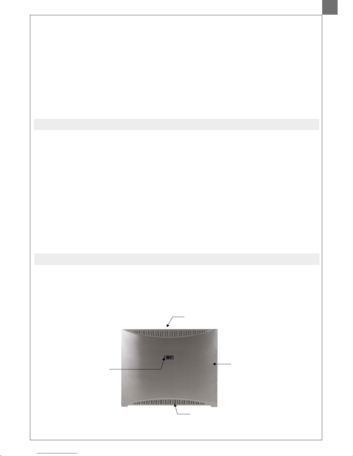
EXHAUST GRID
INTAKE GRID
UNIT COVER
Thank you for your decision to purchase our device.
Please read this user manual carefully before starting to use the device.
Please keep the instructions of this practical quide in order to get a quick know-how.
We do not take any responsibility or provide warranty in case of damage, loss or damnification caused by
incorrect usage or usage for other purposes, not specified in this manual.
Contents: 1. Safety measures
2.
3. Instructions for use
4. Instructions for maintenance
5. Servicing the unit
6. Installation guide
7. Technical data
Usage specification
3.
3.1.
INSTRUCTIONS FOR USE
Humidity regulation with an inbuilt digital humidistat located in the cover of the equipment
3
WALL-MOUNTED SWIMMING POOL DEHUMIDIFIER - OWNER´S & INSTALLATION MANUAL
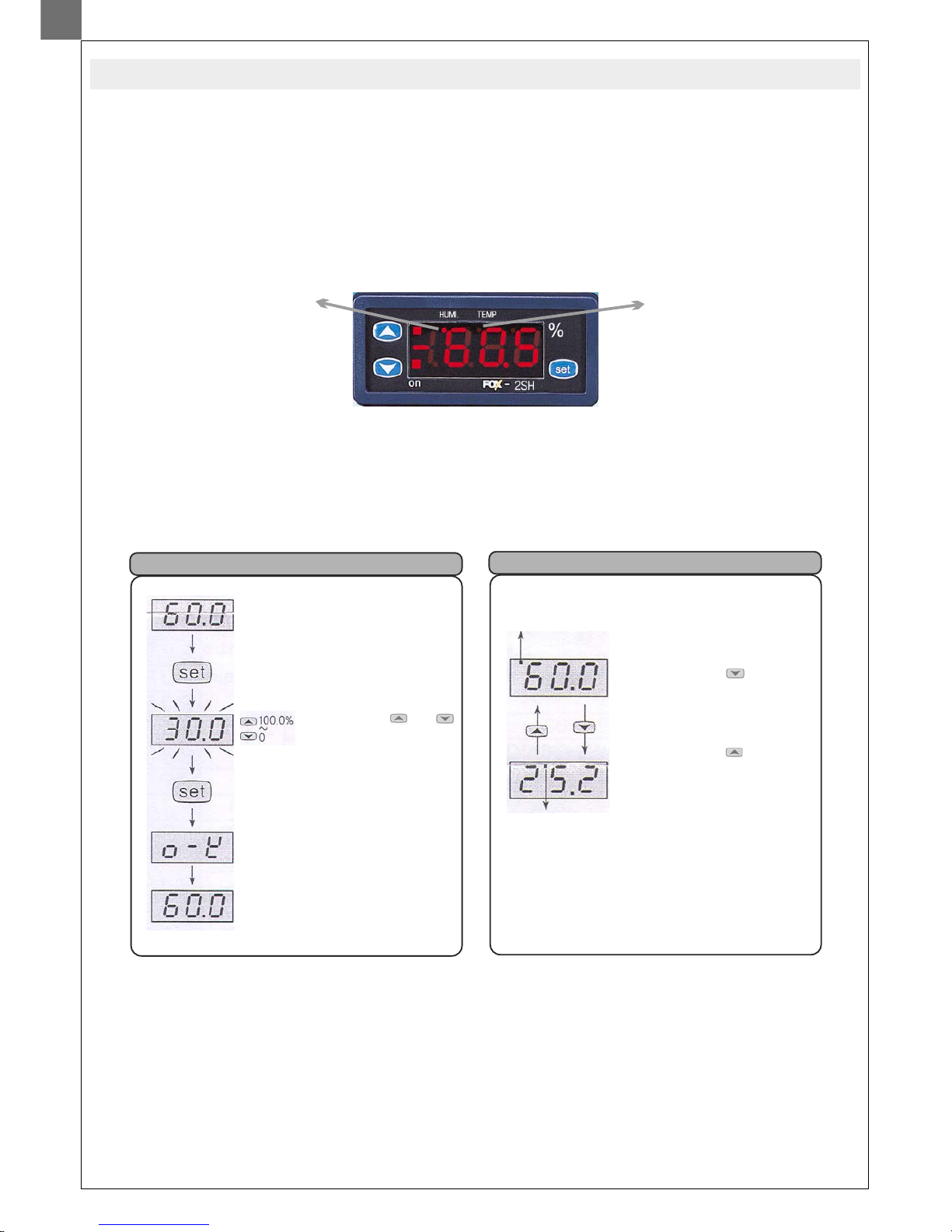
The inbuilt humidistat is located in the cover of the device. It reads the humidiy of the incoming air,anddependingonthesetvalue,
switches on the compressor. In indoor swimming pool halls, the optimal air humidity level should range between 55% and 65 %.
Decreasing the levelofhumidity under the above mentioned range is notdesirable, considerating the physiological aspects as well
as the aspects of providing building protection. Moreover, it increases the consumption of electrical energy.
The humidistat can be
controlled by theuser.
Humidistat display (front view)
Luminous point
signals, that the
humidity is shown on
display.
Luminous point signals,
that the temperature is
shown on display.
Current humidity or current
temperature d
By pressing the “set” button,
the requested value blinks.
By pressing the or
button, the requested
value changes.
By repressing the “set” button
after the requested value has
been changed, “OK” symbol
appears and the requested value
is saved.
isplay.
The current humidity or
temperature is shown on
display.
By pressing the button
when the current humidity is
being displayed, the current
temperature will be shown.
By pressing the button
when the current temperature
is being displayed, the current
humidity will be shown.
Although the current
temperature is shown on
a display, all the functions
work on the basis of the
humidity value.
Humidity setting
Changing the display of humidity and temperature
Luminous point with “HUMI”
symbol on a display frame
signalizes the humidity display.
Luminous point with
“TEMP” symbol on a
display frame signalizes
the temperature
display.
Failure reporting
Memory failure. Switch off and then switch on again the electrical connection.
If the failure reporting continues, please ask us to change the component.
Sensor failure. The electrical connection of the sensor is broken off.
Please control the cable.
Sensor failure. The sensor is short-circuited. Please control the cable.
Er1
0-E
S-E
4
WALL-MOUNTED SWIMMING POOL DEHUMIDIFIER - OWNER´S & INSTALLATION MANUAL
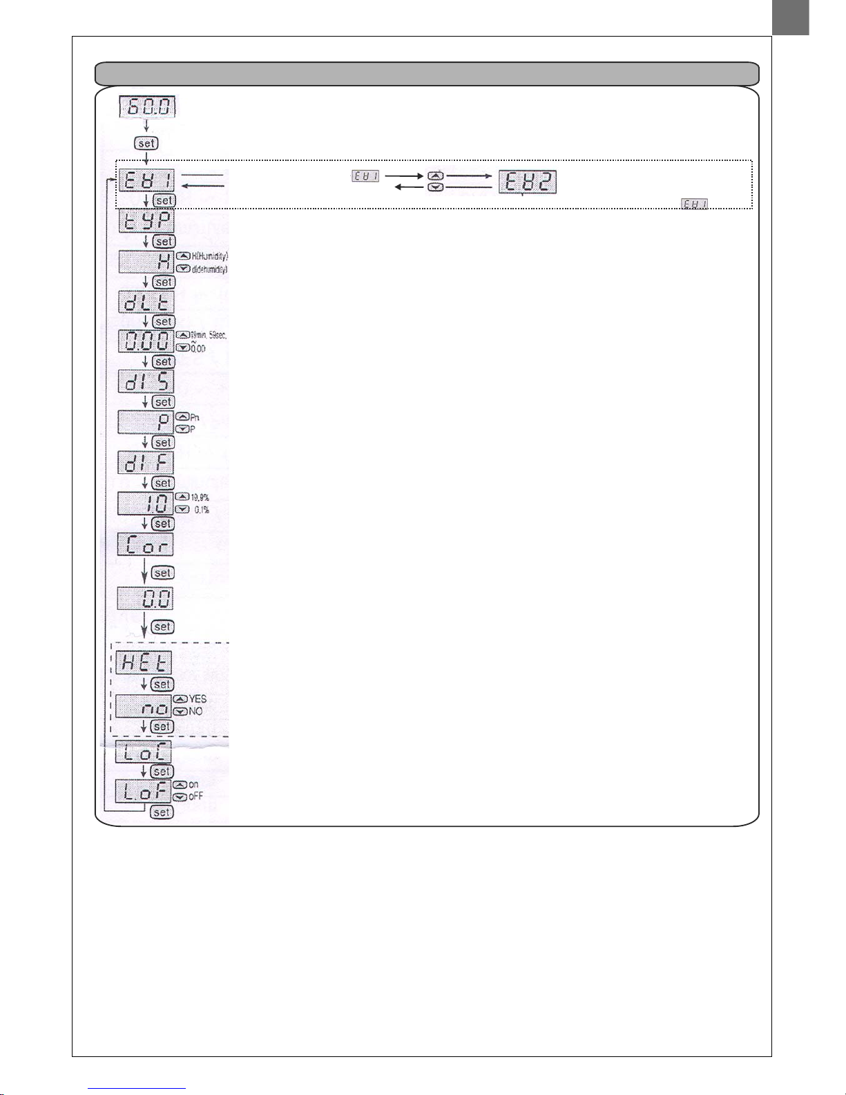
Current humidity or current temperature
display.
Keep the “set” button pressed for longer
than 5 secs.
Function s .
=Humidity
=Dehumidity
Delayed time on the output. Used mainly
for device protection and in case of very
frequent switching on and switching off.
Setting of the deviation type.
Pn=+/- deviation
Setting of the humidity hysteresis (zone
of insensitiveness) - difference between
closure and opening points.
In case the control circuit reacts too
slowly, reduce the hysteresis. In case the
control circuit is unstable (switches on and
off alternately), increase the hysteresis.
The correction function is used in case of
difference between the currently shown
value and the real exact value (detected
by etalon, e.g.)
HEt /heating/ Switching on of the heating
element on the humidity sensor FOX-2SH
is used for its prevention from misting, in
case the humidity is higher than 95% RH.
Switching on the “Lock function” - function
of set values´protection.
Lon= switching on the “Lock function”
LoF= cancellation of
Programming point “1”
Setting of the main output´values
etting
P=+deviation
the “Lock function”
Program setting
By keeping the “set” button pressed for longer than 5 secs, the setting gets finished and you return to a mode of current
humidity display.
In case of inactiveness for longer than 30 secs, this is done automatically.
Setting of the additional output
which is not connected.
Don´t perform any settings here
and return to the point
5
WALL-MOUNTED SWIMMING POOL DEHUMIDIFIER - OWNER´S & INSTALLATION MANUAL
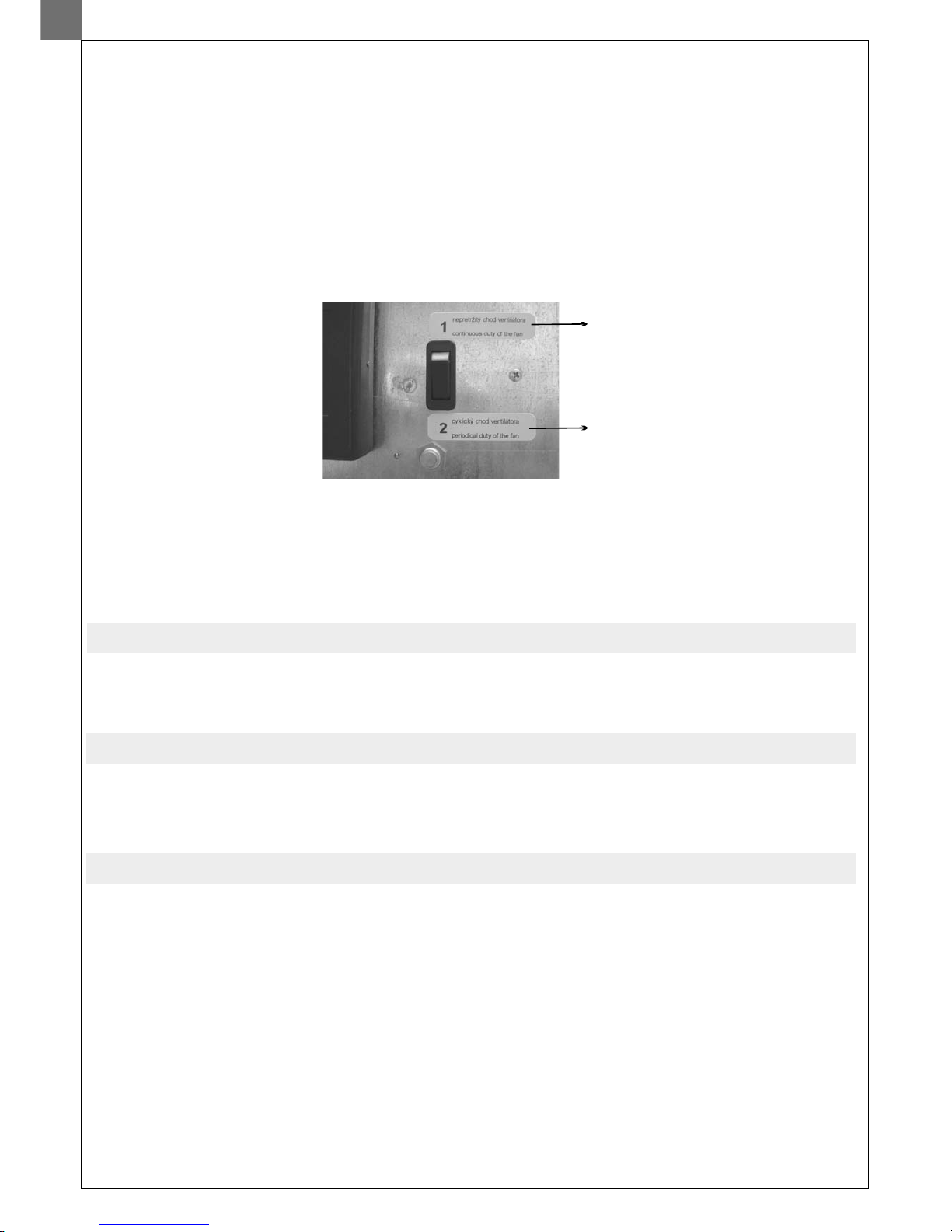
Under the inside coverofthe unit, thereis a two-positional fan modeswitch. In the firstposition, the fan runs evenif the compressor
of the appliance has stopped continuous operation of the fan. In the second position, the fan only runs simultaneously with the
compressor periodical duty ofthe fan. The continuousoperation mode ofthe fan is preferable, since the humidity readerbuilt in the
device continuously reads humidity, and thereforea greater accuracy isreached. Atthe sametime, continuous operation ofthe fan
results in better air circulation in the room. The installation worksupplier selects the mode of the fan according to the request of the
user.
:
:
3.3. Fan regulation
3.2. Humidity regulation with a back-up mechanical humidistat located in the electronic box
In the electronicbox there is a back-up mechanical humidistat, which is set on the value of 70 % RH. This humidistat has a back-up
function in caseof digital humidistat failure.User should not perform any regulation of this humidistat.
Switch of fan operation
Continuous duty of the fan
Periodical duty of the fan
The compressor´s operation starting is for securing its protection, delayed by min. 3 minutes. Depending on the humidity of
environment, it maylast even longer.The user mustnot manipulate with the settingelement of a timerelay.
3.4. Compressor regulation
It is necessary to make sure that the intake- and exhaust outlet are not covered. It is forbidden to place towels or clothes on the
exhaust outlet, to dry them. Cleaning the device´s cover can be done only using grooming articles suitable for rustless steel
surfaces. In casethere is a waterdripping from the equipment,check whether a condensate pipeis not obstructed.
At least oncea year, itis necessary to have the unitchecked and cleaned by aservice specialist. This is necessary in orderto secure a
long operational life of the device. Cleaning the interior parts of the device by a user is not recommended, as this may lead to a
damage on the unit. Thedevice containsmobile elementsas wellas elementsunder electricalpressure, thereforethe interiorparts
can be cleanedonly by a certified electricianwith an appropriate knowlegdeof refrigerating technology.
The unit must be installed in compliance with the local installation and electrical installation regulations !
6.1. Unit location
The unit is to be installed on the wall or on the mobile stand. To ensure the right operations of the dehumidifier and its maximum
efficiency in terms of humidity control, it is necessary ensure proper air circulation into and from the dehumidifier. This requires
the actual unit placement appropriately into the swimmingpool hall respecting basic prerequisites of air circulation and air flow. It is
strictly forbidden to install the unit just below the ceiling. At least 200mm of a free space must be kept above the unit and at least
150mm below theunit. Each swimming pool hall is individual thus aspecial care needs to be taken to choose a proper dehumidifier
placement. It isforbidden to install theunit on the ground. Itis also strictly forbiddento block the airinlet and outlet with anyobjects
(canoe, buckets, ceiling beams, etc.). For maintenance purposes please keep free space of 200mm on both sides
of the dehumidifier.
to
4. MAINTENANCE INSTRUCTIONS
5. SERVICING THE UNIT
6. INSTALLATION GUIDE
6
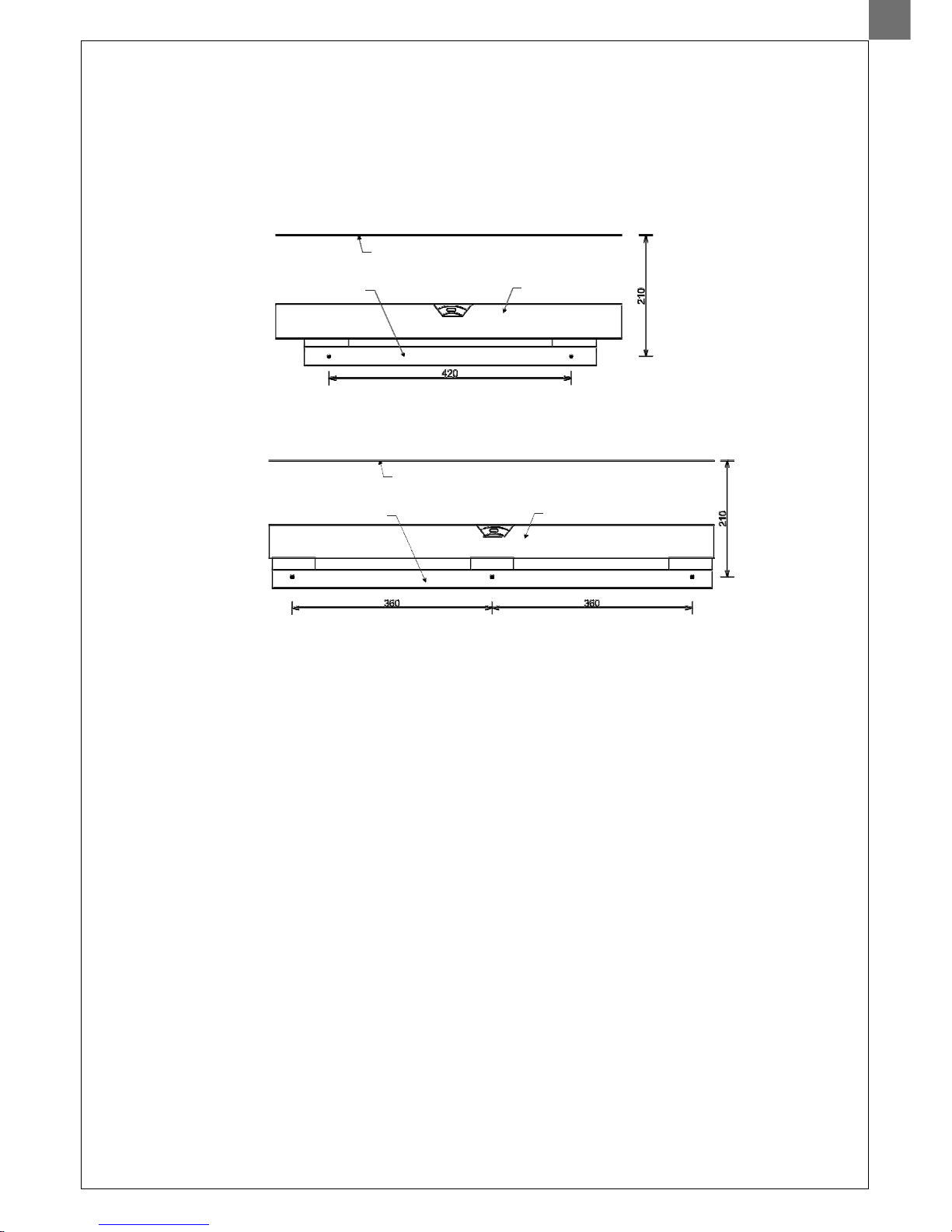
The equipment hasa self-supporting construction and is very easy toinstall.
There is an installationbracket included in theequipment accessories, which must be fixedon the wall. The axisof the fixation slots
is 210 mmlower than the top edge of the device. The distance between the fixation slots is 420 mm (DRY 300 SILVER/METAL) and
360 mm (DRY500 SILVER/METAL). When thebracket is fixed,it is possible tohang up the device withoutdismounting its cover.
6.2. Equipment fixation
Model DRY 300 SILVER/METAL
Model DRY 500 SILVER/METAL
TOP EDGE OF THE DEVICE
BRACKET
SPIRIT LEVEL
FIXATION SLOTS
The cover can be dismounted after releasing two screws (DRY 300 S ) or three screws (DRY 500 S )
at the bottom of thedevice. Release thescrews, pull the bottom part of the cover toward yourself and then, by lifting it shortly, rake
down the coverfrom the rear plate.Tomount the cover, carry theprocedure out in reverse order.
ILVER/METAL ILVER/METAL
6.3. Dismounting and mounting of the cover
TOP EDGE OF THE DEVICE
BRACKET
SPIRIT LEVEL
FIXATION SLOTS
WALL-MOUNTED SWIMMING POOL DEHUMIDIFIER - OWNER´S & INSTALLATION MANUAL
 Loading...