

Page 1
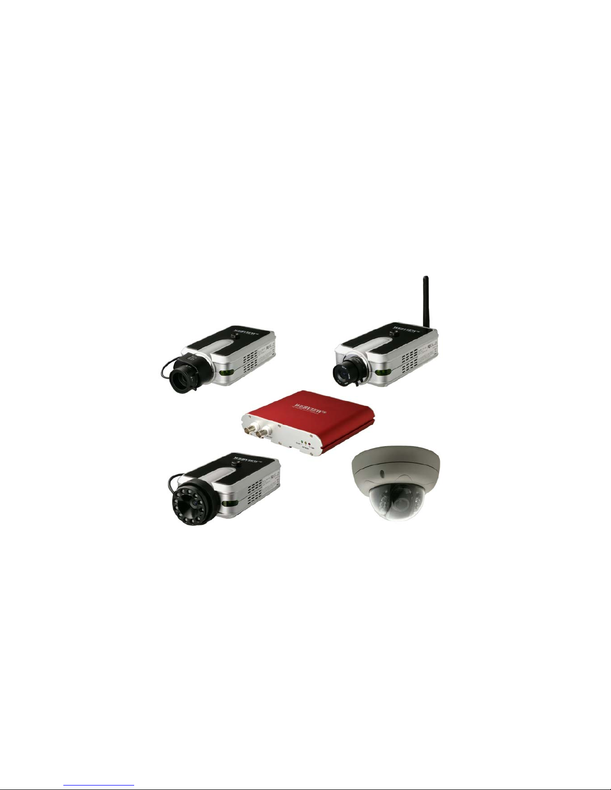
PRO SERIES Network Camera &
Video Server
USER MANUAL
Version 2.0.2
Released on 2
nd
of June, 2008
Microweb Co., Ltd.
Page 2

2
Table of Contents
Safety and Regulatory Notices ....................................................................................................4.
Section 1: Product Overview
1.1 About the Pro Series Network Cameras and Video Servers........................................... 7
1.2 Main Features and Benefits .............................................................................................7
Section 2: Physical Description
2.1 Package Contents .......................................................................................................... 8
2.2 MPEG4 CCD Camera..................................................................................................... 9
2.3 MPEG4 CCD IR Camera…….........................................................................................11
2.4 Network Video Server…..……........................................................................................12
2.5 Vandal-Proof Dome Camera …..................................................................................... 13
Section 3: Installation Summary and Examples ........................................................................ 14
Section 4: Assigning an IP address and Accessing the Camera’s Homepage
4.1 Connecting the Camera to a PC ....................................................................................17
4.2 Setting Up the IP address Using IP Installer ................................................................. 17
4.3 Accessing the Camera’s Homepage ..............................................................................19
4.4 Homepage Options (MPEG4 Cameras)..........................................................................24
Section 5: Adjusting the Camera Lens
5.1 Adjusting the Focus ....................................................................................................... 27
5.2 Replacing the Lens .........................................................................................................28
Section 6: Administrator Menu
6.1 Overview of the Administrator Menu ...............................................................................29
6.2 Image Configuration ……………………………………………………………………………30
6.3 Network Configuration …………………………………………………………………………35
6.4 User Configuration ……………………………………………………………………………..38
6.5 Event Trigger Configuration …………………………………………………………………...39
6.6 System Configuration …………………………………………………………………………..43
6.7 Wireless Configuration
6.7.1 Wireless Setup…........................................................................................................ 46
6.7.2 Wireless Security Settings …………............................................................................46
Page 3

3
Section 7: PoE Support.............................................................................................................. 49
Section 8: ETSP Client Software.................................................................................................50
Section 9: RTSP Video Playback ...............................................................................................54
Section 10: SSL Encryption / Access via HTTPS.......................................................................56
Section 11: Remote Access to a Camera & Router Setup…….................................................. 58
Section 12: Developer Information
12.1 Software Development Kit (SDK)…………………………............................................. 61
12.2 Direct Access to Internal JPEG…………………………................................................ 62
12.3 Motion-JPEG Access (MPEG4/M-JPEG models only) ................................................ 62
Appendix A: Frequently Asked Questions (FAQ)......................................................................... 63
Appendix B: Accessing the Camera via HyperTerminal…………………..................................... 67
Appendix C: Troubleshooting....................................................................................................... 69
Appendix D: Utilizing IP addresses on a Local Network…………................................................ 71
Appendix E: Updating Firmware................................................................................................... 73
Appendix F: The I/O Connector ................................................................................................... 75
Appendix G: Dynamic Domain Name System (DDNS)................................................................ 76
Appendix H: Reinstating the Factory Default Settings.................................................................. 83
Appendix I: Glossary of Terms .................................................................................................... 84
Appendix J: Product Specifications………………………….......................................................... 85
Page 4

4
About this Document
Thank you for purchasing this WEBVIEW™ Pro Series Network Camera or Network Video Server.
This user manual includes instructions for using and managing the camera on your network.
Networking experience will be helpful when setting up and using this product. Updated versions of
this document will be posted to www.networkipcam.com
as they become available.
Legal Considerations
Video and audio surveillance can be prohibited by laws that vary from country to country. Please check
the laws in your local region before using this product for surveillance purposes.
Electromagnetic Compatibility (EMC)
This equipment generates radio frequency energy and, if not installed and used in accordance with
the instructions, may cause harmful interference to radio communications. However, there is no
guarantee that interference will not occur in a particular installation. If this equipment does cause
harmful interference to radio or television reception, which can be determined by turning the
equipment off and on, the user is encouraged to try to correct the interference by one or more of the
following measures:
- Re-orient or relocate the receiving antenna.
- Increase the separation between the equipment and receiver.
- Connect the equipment to an outlet on a different circuit than the receiver.
- Consult your dealer or an experienced radio/TV technician for help.
- Check that shielded (STP) network cables are being used with this unit to ensure compliance with
EMC standards.
This equipment has been tested and found to comply with the limits for a Class B computing device
pursuant to Subpart B of Part 15 of FCC rules, which are designed to provide reasonable protection
against such interference when operated in a commercial environment. Operation of this equipment in
a residential area is likely to cause interference, in which case the user, at his own expense, will be
required to take whatever measures may be required to correct the interference. This digital equipment
fulfills the requirements for radiated emission according to limit B of EN55022/1998, and the
requirements for immunity according to EN55024/1998 residential, commercial and light industry.
Safety
This equipment complies with EN 60950, Safety of Information Technology equipment.
Radio Transmission Regulatory Information
This equipment generates and radiates radio frequency energy, and must be installed and operated
while maintaining a minimum body-to-camera distance of 3 feet (1 meter).
Tested to comply with FCC Standards FOR HOME OR OFFICE USE.
This product must be installed and used in strict accordance with the instructions given in the user
documentation.
This product complies with the following radio frequency and safety standards:
Europe -EU Declaration of Conformity.
This device complies with the requirements of the R&TTE Directive 1999/5/EC with essential test
suites as per standards EN 301489: General EMC requirements for radio equipment; and ETS 300328:
Technical requirements for radio equipment.
USA -Federal Communications Commission (FCC): This device complies with Part 15 of FCC Rules.
Operation of the device is subject to the following two conditions:
1. This device may not cause harmful interference.
2. This device must accept any interference that may cause undesired operation.
Trademark Acknowled g m en ts
Ethernet, Internet Explorer, Linux, Microsoft, Mozilla, Netscape Navigator, OS/2, UNIX, Windows,
WWW are registered trademarks of the respective holders. Java and all Java-based trademarks and
Page 5

5
logos are trademarks or registered trademarks of Sun Microsystems, Inc. in the United States and
other countries.
Video Standard and Product Classification
As the video standard varies from country to country, users are asked to check it first and choose
the right model. The two most common video standards used are NTSC and PAL. NTSC is the video
system or standard used in North America and most of South America. In NTSC, 30 frames are
transmitted each second. Each frame is made up of 525 individual scan lines. PAL is the
predominant video system or standard mostly used overseas. In PAL, 25 frames are transmitted
each second. Each frame is made up of 625 individual scan lines.
These are the products represented in this user manual:
MNC-L200N: Wired MPEG4/JPEG CCD Network Camera for NTSC standard
MNC-L200P: Wired MPEG4/JPEG CCD Network Camera for PAL standard
MNC-W200N: Wireless MPEG4/JPEG CCD Network Camera for NTSC standard
MNC-W200P: Wireless MPEG4/JPEG CCD Network Camera for PAL standard
MNC-L200NIR: Wired MPEG4/JPEG CCD IR Network Camera for NTSC standard
MNC-L200PIR: Wired MPEG4/JPEG CCD IR Network Camera for PAL standard
MNC-W200NIR: Wireless MPEG4/JPEG CCD IR Network Camera for NTSC standard
MNC-W200PIR: Wireless MPEG4/JPEG CCD IR Network Camera for PAL standard
MNC-L200M20: 2.0 Megapixel Wired MPEG4/JPEG CMOS Network Camera
MNC-W200M20: 2.0 Megapixel Wireless MPEG4/JPEG CMOS Network Camera
MNS-202: Wired MPEG4/JPEG Network Video Server for NTSC & PAL standards
MNC-300VN: Vandal Proof Dome Camera for NTSC standard
MNC-300VP: Vandal Proof Dome Camera for PAL standard
MNC-XXXTDN : True Day & Night Version
(MNC-L200N(P)TDN / MNC-W200N(P)TDN / MNC-300VN(P)TDN)
MNC-XXXTDNIR : True Day & Night with IR Night Vision Version (MNC-300VN(P)TDNIR)
To determine your video standard, refer to the lists below.
PAL: Afghanistan, Algeria, Argentina, Austria, Australia, Bangladesh, Belgium, Brazil, China, Denmark,
Finland, Germany, Hong Kong, Iceland, India, Indonesia, Iraq, Ireland, Israel, Italy, Jordan, Kenya,
Kuwait, Liberia, Malaysia, Netherlands, Nigeria, Norway, New Guinea, Pakistan, Singapore, South
Africa, Southwest Africa, Sudan, Sweden, Switzerland, Thailand, Turkey, Uganda, United Kingdom,
United Arab Emirates, Yugoslavia, Zambia
NTSC: Canada, Chile, Costa Rica, Cuba, Dominican Republic, Ecuador, Japan, Mexico, Nicaragua,
Panama, Peru, Philippines, Puerto Rico, South Korea, Taiwan, USA. Users are asked to read the
following before using the Pro Series Network Camera.
Page 6

6
Important Notices
1. Camera surveillance laws may differ for each country. Contact the local authorities to avoid
any surveillance law violations.
2. Note that the CCD lens that comes with the Pro Series Network Camera can be damaged
permanently if exposed to direct sunlight. If your application demands prolonged exposure to
sunlight, you should consider equipping it with a sun visor.
3. The Pro Series Network Camera is not weatherproof. Be aware of environmental
specifications included in the manual. For outdoor use, use a weatherproof case to protect the
camera from water, moisture or temperature (higher or lower than specifications). For camera
cleaning, gently wipe with a clean, dry cloth.
4. Be sure to use only the DC adapter provided with your camera. Connecting the camera
directly to AC current may cause electrical damage to the camera.
5. Be careful when handling the camera. Physical shocks can cause serious damage.
6. Be sure to mount the camera securely to avoid any personal injuries. Keep the camera out of
reach of children.
7. If the camera does not operate properly, contact your local distributor. Do not disassemble the
product, as that may void the warranty.
8. Specifications are subject to change without prior notice to enhance the product quality
and stability.
9. The contents of this manual may differ from actual products due to product upgrade or
enhancement.
Page 7

7
1: Product Overview
1.1 About the Pro Series Network Cameras and Video Servers
The Pro Series Network Cameras and Network Video Server are all-in-one networking devices that
contain a digital color camera (or a connection for analog CCTV cameras), a powerful Web server, an
optimized embedded operating system, hardware for image compression and a physical Ethernet
connection. The products do not need any additional software or hardware. Simply provide power,
connect an Ethernet cable and view from any computer on the network. For the Network Video Server,
you need a conventional CCTV camera as your video input source. The WEBVIEW Pro Series
Network Cameras and Network Video Servers are ideal for surveillance applications that require
high-quality, full-motion video and audio, as well as comparatively low bandwidth demands on the
network. These products provide an easy user interface for remote access to receive the optimal
synchronized video and audio from anywhere, anytime over the Internet with the popular Internet
Explorer Web browser, as easy as surfing any regular Web sites. More than just a high-performance
network camera, the Pro Series Network Cameras and Network Video Server also offer many
advanced features to provide solutions such as remote surveillance, home/business security,
audio/video conferencing, motion detection and more.
NOTE: This user manual includes the Network Video Server whenever it refers to Pro Series Network
Cameras.
1.2 Main Features and Benefits
Convenient Operation
The Pro Series Network Camera does not need any additional software or interaction with any other
server. The only software needed is a common Web browser, such as Microsoft Internet Explorer 5.x
or above.
Open Standards
The Pro Series Network Camera supports TCP/IP networking, SMTP e-mail, FTP, HTTP and other
Internet-related protocols. The camera can be used in a mixed operating system environment with
Windows, Unix, Mac and OS/2. It integrates easily into other www/Intranet applications and CGI
scripts.
Simple Administration
Using a standard Web browser, you can configure and manage the Pro Series Network Camera
directly from its own embedded Web pages. The embedded operating system is upgradeable through
the network; check with your local WEBVIEW dealer for firmware upgrades.
External Devices
The auxiliary Input/Output connector on the camera allows you to connect to a variety of
external devices, such as IR sensors, switches and alarm relays.
Security
Your Pro Series Network Camera includes a self-contained Web server, which means that digital
images can be secured like any other Internet host. Your network administrator, using the unit’s
security settings in combination with an organization’s Internet firewall, normally implements data
protection. The administrator can decide whether individuals, groups or the whole world may access
the camera. The Pro Series Network Camera supports multi-user password protection.
Compression and Performance
With a variable frame rate dependent on the image quality and bit rate, the camera delivers
MPEG4 video at up to 30 images per second.
Page 8

8
Dual Mode Compression
For application providers, system integrators and other APs, this camera supports three types of video:
1) MPEG4 video; 2) M-JPEG compression; and 3) MPEG4+M-JPEG mode.
Full Duplex Two-Way Audio
Full duplex two-way audio is available by connecting an external microphone and speaker to the
camera.
IEEE 802.3af Standard PoE (Power over Ethernet) Supported
Software
IP Installer for quick installation
Webview manager for viewing and recording multi cameras up to 16 channels in a screen
ETSP Client Motion Detection Recording Utility
Check http://www.networkipcam.com
for latest versions.
2: Physical Description
2.1 Package Contents
Check all items packed inside the box as listed below.
ITEM DESCRIPTION
Network Camera or Video
Server
MPEG4/JPEG dual mode Network
Camera
Installation CD
IP Installer, upgrade program,
Manual, Webview Manager, etc.
Power Supply AC power adapter and power cord
Stand Wall & table stand*
Connection (Console) Cable RS-232 cable
User Manual Hard-copy book
* You can use a standard camera stand or tripod for the Pro Series Network Camera.
Page 9
9
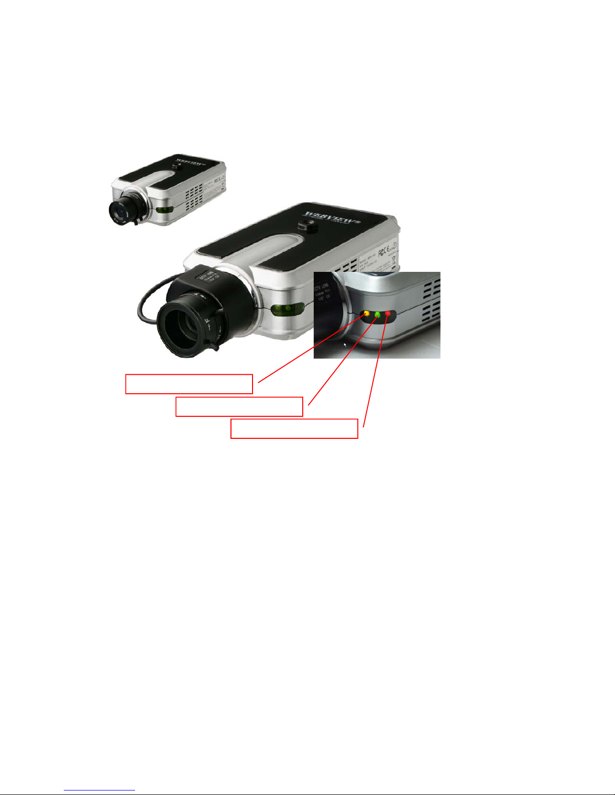
2.2 MPEG4 CCD and CMOS Camera Front View
Power LED (Red): Once power is supplied to the camera, the red LED will light.
Operating Status LED (Green): This LED indicates the camera’s operating status. Once power is
supplied, the LED lights and then blinks once every second as long as the video is transmitted on the
network during normal operation. When there is no video transmission, the LED stops blinking. Under
an event-trigger situation, the green LED becomes red and blinks rapidly. During simultaneous
operation of event-trigger capture and video monitoring, it blinks rapidly and alternates between red
and green. When you click the "camera off" button in the administrator’s menu, the green LED turns
yellow, which shows that your IP camera has stopped transmitting video and audio.
Network Activity LED (Yellow): This LED indicates network activity. When lit, the network is up and
running; when off, the network is down and not working.
Network Activity LED
Operating Status LED
Power LED
Page 10
10
Rear View
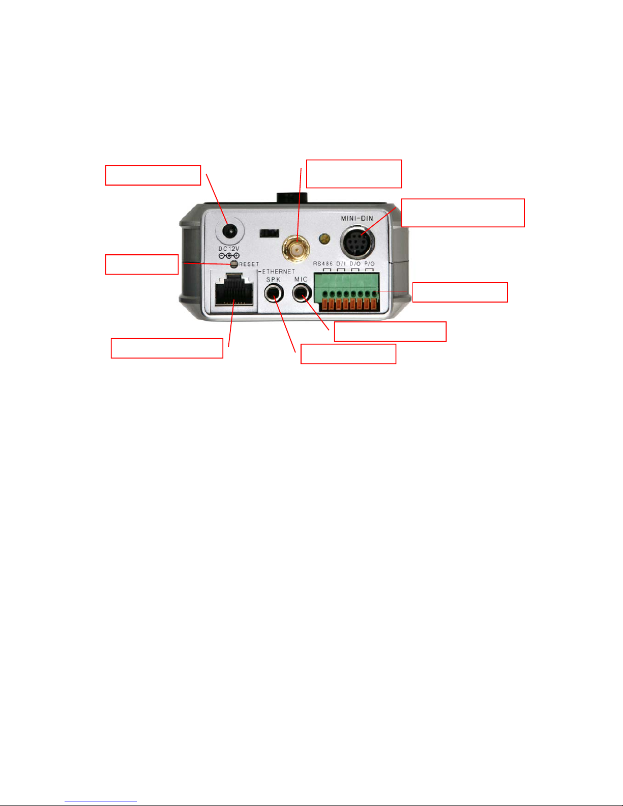
Power Connector: Only use the supplied AC adapter to avoid any possible damage from electric
shock.
Network Connector: Connect 10Base-T Ethernet or 100Base-TX Fast Ethernet cable.
GPIO Connector: To connect external devices such as infrared sensors, alarms or motion detectors
(refer to Appendix F: I/O Connector).
Mini DIN Connector: To connect external devices such as the external zoom/focus lens mechanism,
or to connect directly to a serial port for camera configuration via HyperTerminal.
SPK: Use to connect to an external speaker for audio communication. The audio sent over the network
from a connected client computer can be delivered through this externally connected speaker.
MIC: The external microphone for audio input. The live audio can be captured and transmitted to the
connected camera client via the use of this MIC.
NOTE: The Pro Series Network Camera is compatible with 3.5mm stereo microphones. If you are a
3.5mm mono microphone user, use the included 3.5mm stereo plug to two 3.5mm mono jack converter.
Then you can utilize two mono microphones simultaneously.
RESET: Restore the factory default settings.
Power Connecto r
Wireless Antenna
(
Wireless Models
)
Mini DIN for RS-232
Communication
GPIO Connector
External Microphone
External Speaker
Network Connector
Reset Button
Page 11
11
2.3 MPEG4 CCD IR Camera
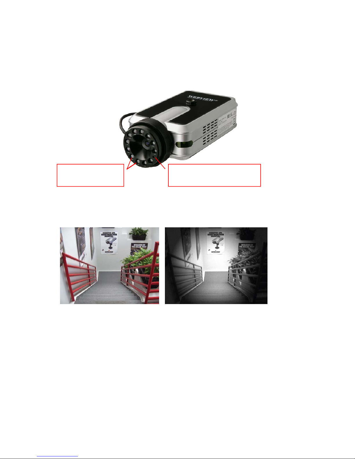
The IR camera has the exact same connectors and LED’s as the standard models. The difference is
the lens and the CCD image sensor.
Captured image from MPEG4 CCD IR Camera –Left : Daytime, Right : Nighttime
Infrared Emitter Diodes
LED’s automatically
turn on in the dark
Light Sensor
Measures the light level and
activates the IR LED’s in the dark
Page 12
12
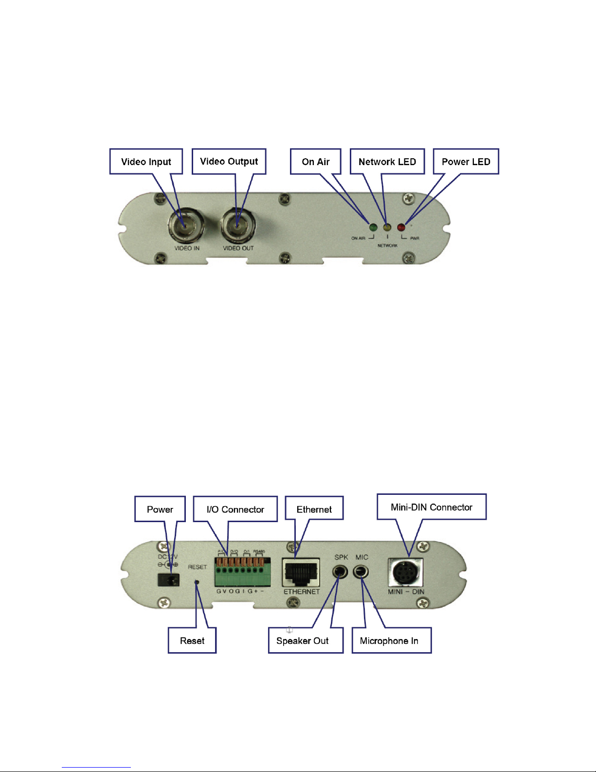
2.4 Network Video Server
Front view
Video Input: To input video signal through a coaxial cable
Video Output: To output video signal through a coaxial cable.
On Air LED (Green): This LED indicates the Video Servers operating status. Once power is supplied,
the LED lights and then blinks once every second as long as the video is transmitted on the network
during normal operation. When there is no video transmission, the LED stops blinking. Under an
event-trigger situation, the green LED becomes red and blinks rapidly. During simultaneous operation
of event-trigger capture and video monitoring, it blinks rapidly and alternates between red and green.
When you click "Video Server off" in the administrator’s menu, this green LED turns yellow, which
shows that the IP Video Server has stopped transmitting video and audio.
Network Activity LED (Yellow): This LED indicates network activity. When lit, the network is up and
running; when off, the network is down and not working.
Power LED (Red): Once power is supplied to the Video Server, the red LED will light.
Power Connector: Only use the supplied AC adapter to avoid any possible damage from
electric shock.
RESET: Restore the factory default settings.
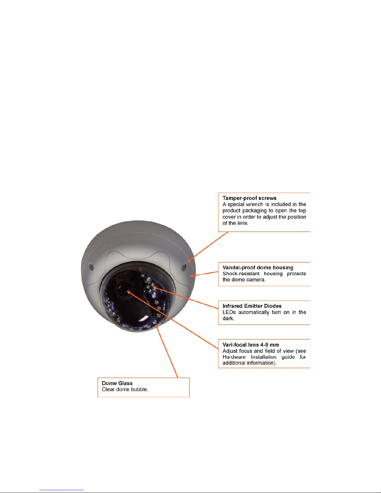
Rear view
Page 13
13
I/O Connector: To connect external devices such as infrared sensors, alarms or motion
detectors (refer to Appendix F: I/O Connector).
Ethernet (Network Connector): Connect 10Base-T Ethernet or 100Base-TX Fast Ethernet cable.
SPK: Use to connect to an external speaker for audio communication. The audio sent over the network
from a connected Video Server client can be delivered through this externally connected speaker.
MIC: The external microphone for audio input. The live audio can be captured and transmitted to the
connected Video Server client by using of this port.
Mini-DIN Connector: To connect external devices such as the external zoom/focus lens
mechanism, or to connect directly to a serial port for Video Server configuration via
HyperTerminal.
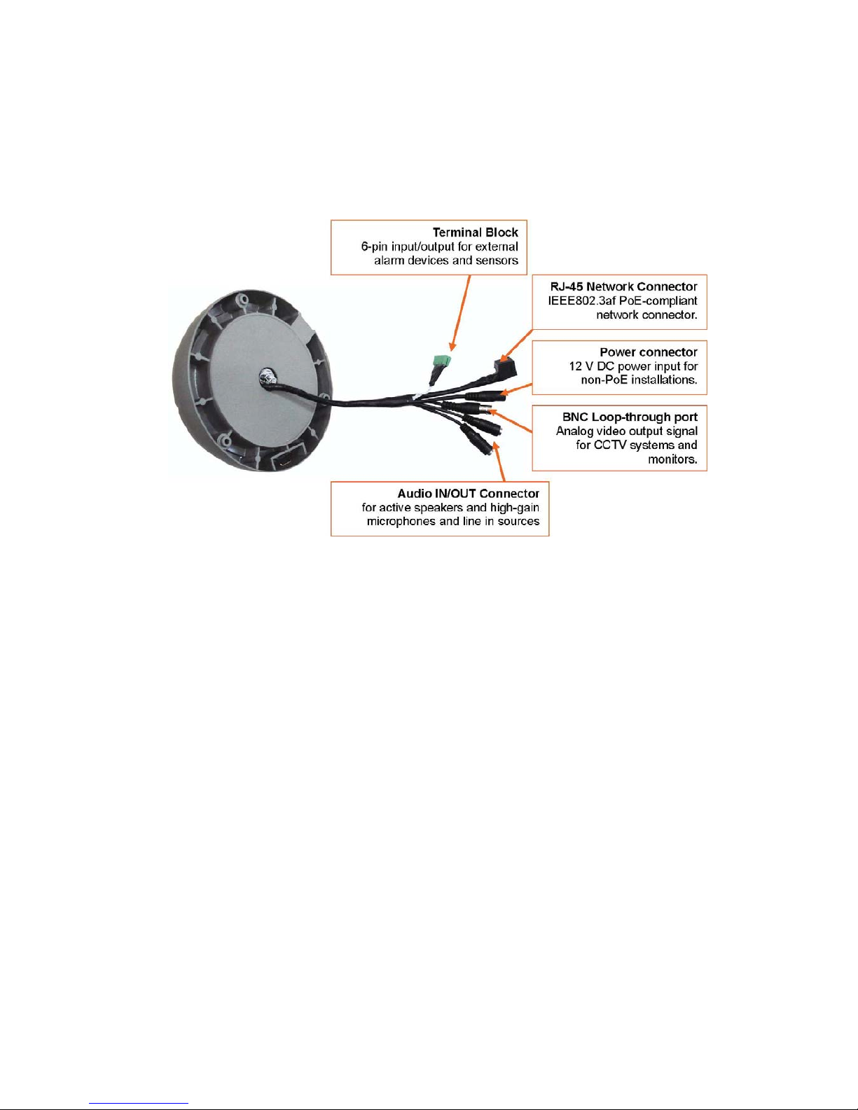
2.5 Vandal Proof Dome Camera
Front View
(Model : MNC-300VTDNIR Night Vision)
Page 14
14
Rear View
RS232 Connector
Serial port connection for HyperTerminal access; See Appendix B.
Network Connector
Connect 10Base-T Ethernet or 100Base-TX Fast Ethernet cable.
Power Connector
Input connector for external 12 V DC Power supply.
Terminal Block
Connect external devices such as sensors and alarm devices, or power external devices through the
camera; See Appendix F for details.
3: Installation Summary and Examples
1. Connect the Ethernet and power to the Pro Series Network Camera.
2. Install and launch the IP Installer program on the enclosed CD.
3. Assign an IP address and network settings.
4. Securely mount the camera. Owners of the indoor fixed dome camera need to refer to the
included Hardware Installation guide.
5. Adjust the lens focus.
Page 15
15
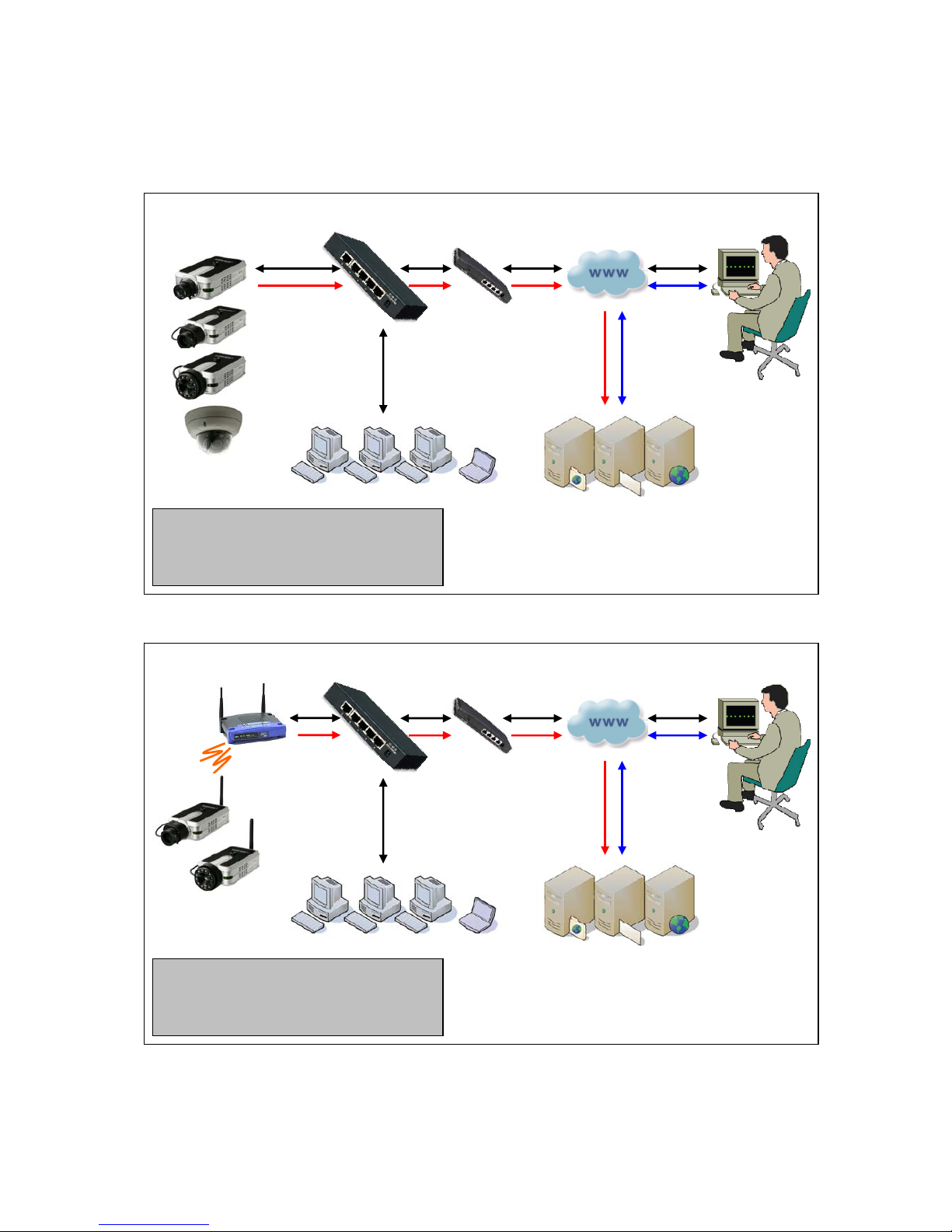
Installation Example: Wired Camera
Installation Example: Wireless Camera
LAN Switch Route
r
Internet (WAN)
Remote Access
Network Cameras
& Video Servers
Local Access
e-mail / FTP / Web Server
Legend (Cable color) :
- Web Browser access to camera
- Access to e-mail, FTP or Web server
- Transmission of AVI files by camera
LAN Switch Route
r
Internet (WAN)
Remote Access
Wireless Network
Cameras
Local Access
e-mail / FTP / Web Server
Legend (Cable color) :
- Web Browser access to camera
- Access to e-mail, FTP or Web server
- Transmission of AVI files by camera
Wireless
Access Point
Page 16
16
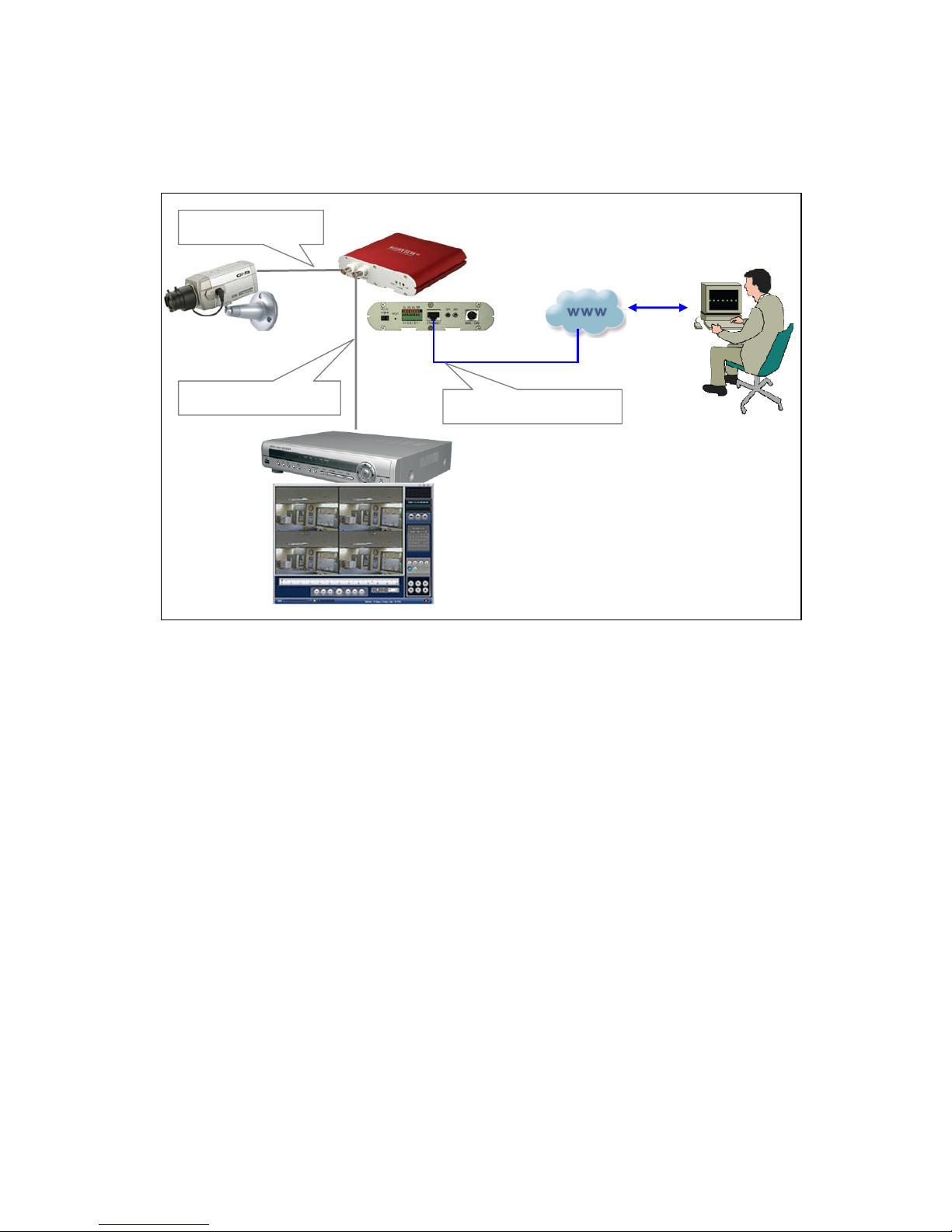
Installation Example: Network Video Server
Remote Access
Network Video Server
CCTV Camera
Analog BNC Input
Analog BNC Output
TCP/IP RJ45 Ethernet
Network
(
WAN/LAN)
DVR
,
VCR, etc.
Page 17
17
4. Assigning an IP Address and Accessing the Camera’s Homepage
4.1 Connecting the Camera to a PC
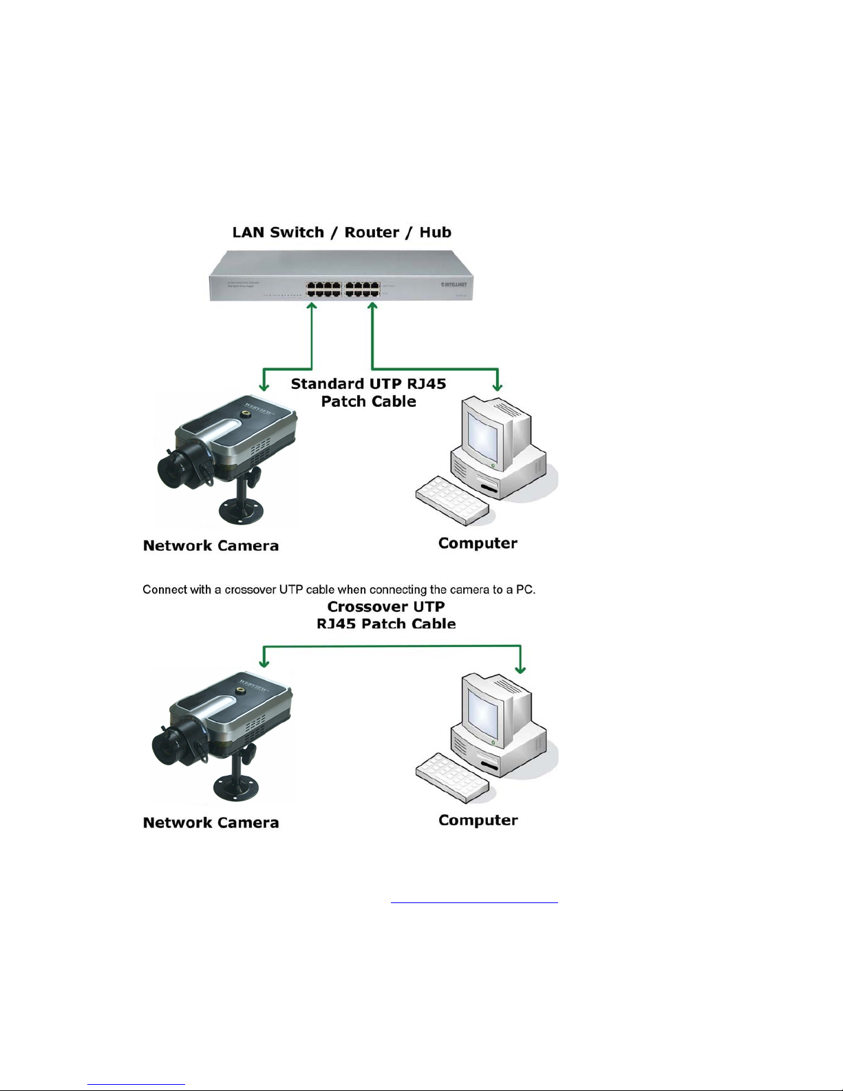
Connect with a direct cable (non-crossover UTP cable) when connecting the camera to a switch, hub
or router.
4.2 Setting up the IP Address Using IP Installer
To access the camera, you need to assign an appropriate network IP address. Run the IP address
installation program (IP Installer.exe) on a PC that is connected to the same local network as the
camera. You can download IP Installer from http://www.networkipcam.com
. IP Installer is compatible
with Windows 9x, Me, 2000, XP and Vista.
Page 18
18
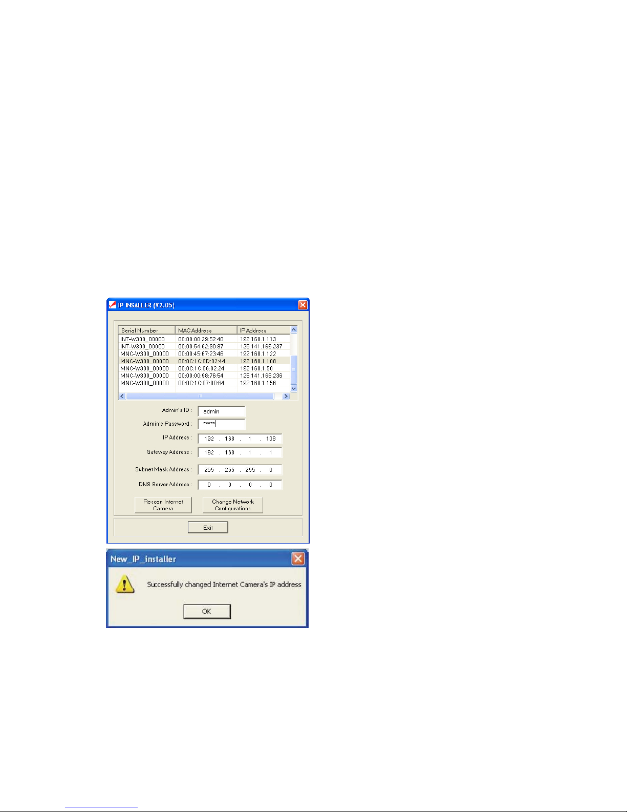
1. Run IP Installer after the camera is booted (wait until the Operating Status LED blinks every
second).
2. Once IP Installer is run, the panel shows every camera connected on the local network. From the
cameras listed, select one to assign a new IP address (every Pro Series Network Camera has a
factory default IP address).
NOTE: The MAC address can be found on the underside label of the camera. To choose a camera,
click on its MAC address on the list.
Enter the administrator ID and password in the blank (default ID and password are both “admin") to
assign or change the IP address for the camera and setup.
Enter the IP address, gateway address, subnet mask address, DNS server address and server IP
address assigned by the network administrator. (When the addresses are not assigned properly, you
cannot access the camera.) The server IP address does not need to be filled out at this time.
After entering all addresses for the camera, click on "Change Network Configurations."
The message shows up if all the information is set up properly.
Then click the "OK" button.
NOTE: After changing the network configuration, it may take a little time to reboot the camera in order
to access the camera’s homepage.
Page 19

19
4.3 Accessing the Camera’s Homepage
Access the camera to monitor real-time images over the Internet and configure the camera settings
through any standard Web browser on a local or remote network. The following Web browsers are
supported.
ٛ - MS Internet Explorer 5.x, 6.x and 7.x (ActiveX + Java)
ٛ - MOZILLA Firefox 1.x., 2.x (Java)
ٛ - MOZILLA 1.x (Java)
ٛ - Opera (Java)
ٛ - Konqueror (Java)
The WEBVIEW Pro Series Network Camera supports two connection methods: ActiveX for
Microsoft's Internet Explorer users on Windows systems; and Java for all other Web browsers and
operating systems, including MacOS and Linux, and Windows when using a different Web browser
than MS Internet Explorer.
ActiveX offers faster performance and enhanced features, such as video recording via Web
browser and two-way audio. Using ActiveX, however, requires the user to be logged in as a
computer administrator. Not everybody has this ability. Furthermore, ActiveX is often banned from
use in corporate environments for security reasons.
Java represents the universal alternative to ActiveX. It can be used on nearly all common computer
operating systems and with almost any common Web browser. The camera primarily supports Java
by Sun Microsystems, but it is also compatible to Microsoft's Java VM. Sun's Java can be downloaded
from http://www.java.com
.
Note: In order to utilize Java, the camera must be operating in JPG Stream mode (see section
6.6. System Configuration).
Before you attempt to connect to the camera with your Web browser, make sure that your setup meets
the following requirements:
1. You have assigned a valid IP address to your camera. The IP address of the camera is in the
same subnet as your computer.
2. You use MS Internet Explorer and have admin authority to install the ActiveX control.
3. You chose to access the camera using Java and have either Java version (SUN or Microsoft)
installed in your computer.
Starting the Web Bro wser
Start your Web browser, entering your camera’s IP address on the address bar in order to
access the login page. The default IP address is 192.168.1.221.
Login Page
After you open the camera address, you will be connected to the login page of the camera. The login
page looks slightly different, depending on the Web browser you are using, and depending on the
streaming mode the camera is set to (see section 6.6 System Configuration).
Below is an overview of the different login screens and stream modes.
Page 20
20
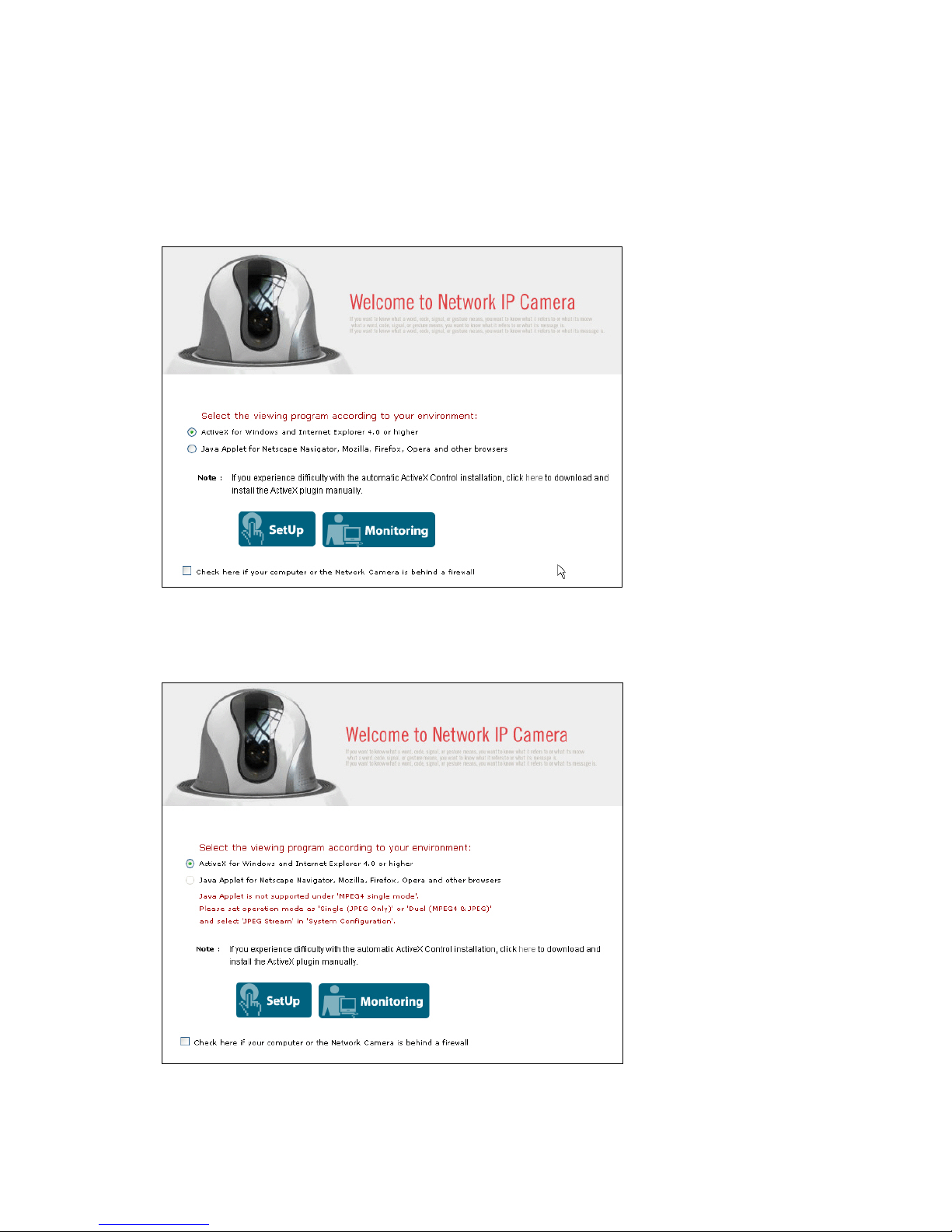
MS Internet Explorer – JPEG Stream Mode
Both options, ActiveX and Java, are available in this operational mode. If you can run and install
ActiveX controls, you should select ActiveX as your preferred viewing program, as it offers higher
frame rates and better functions.
MS Internet Explorer – MPEG4 Stream Mode
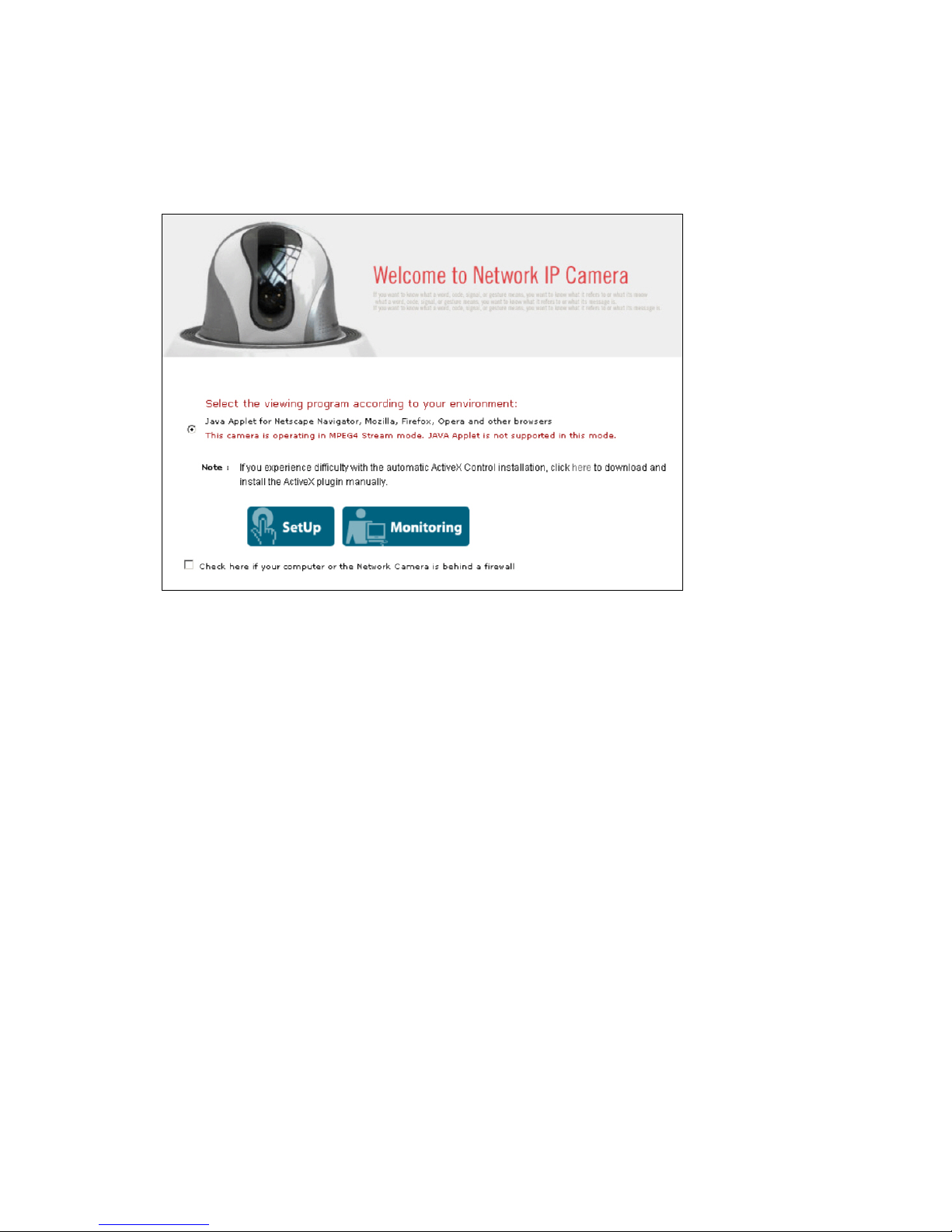
Java is not available in MPEG4 Stream mode and the option is therefore grayed-out.
Page 21
21
Non-MS Internet Explorer – JPEG Stream Mode
Java is the only choice given.
Non-MS Internet Explorer – MPEG4 Stream Mode
Java is the only choice given, but the warning message tells you that even though you are able to login
you won't be able to see the live image as shown in the above. You still can access the administration
menu to make changes to the settings.
SetUp & Monitoring
On the log-in page, there are two modes of starting the IP camera. The one is ‘SetUp’, which starts IP
camera with configuration setting and the other is ‘Monitoring’, which leads you to live view of IP
camera video. Only administrator can start with ‘SetUp’ menu.
Username and Password
Enter a username and password to access the camera. The camera has two default user
accounts.
. Administrator account: View live image and change the camera settings.
Default Username: admin / Default Password: admin
. Guest account: View the live image, but no access to any camera settings.
Default Username: guest / Default Password: guest
Behind a Firewall
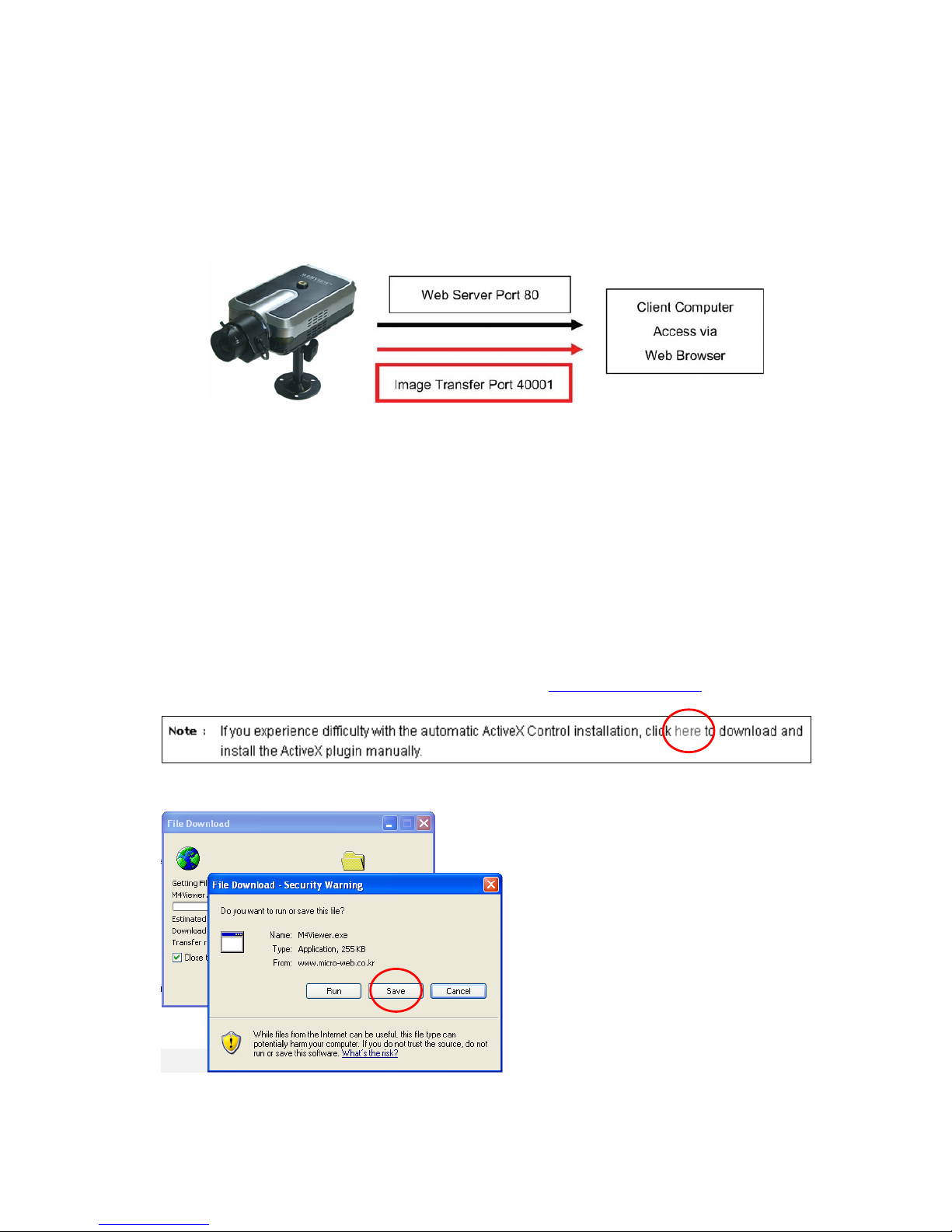
If your PC is connected to a network with a firewall, you may not view real-time video properly because
the video TCP port is blocked. The camera operates on two important ports. One port is the Web
server port (default = 80).The other port is the image transfer port (default = 40001). The camera sends
the user interface pages (such as the login page) via TCP/IP port 80 and the image stream through the
Image Transfer Port 40001. If for whatever reasons the camera cannot send you data via the Image
Transfer Port (e.g., because the port may be blocked on the client computer) or, in case you access
the camera remotely over the Internet, the port may not be properly opened and forwarded in the
Page 22
22
router, and you will not be able to see the live image of the camera. A blocked image transfer port is
the most common cause for display problems.
As a rule: Whenever you can see the login page in your Web browser but no live video shows up on
the main camera live screen, you should activate this option.
ActiveX Installation for MS Explorer Users (automatic)
The first time you login to the camera using ActiveX, you are notified that a required plug-in / ActiveX
control is required. You need to allow the installation of ActiveX by clicking "Yes" to the question "Do
you want to install the program?" on the pop-up window. The installation will then take place. It is
normal for this process to take up to 30 seconds. After the installation you will be taken to the Network
Camera Homepage. If you do not see the message concerning the ActiveX installation, this can have
different causes:
- you are not logged in to your computer as an administrator
- the security settings on your system (Internet Options) prevent the installation of signed
ActiveX controls
ActiveX Installation for MS Explorer Users (Manual installation)
If the ActiveX program fails to install automatically, you can install it manually. Administrator rights
are still required.
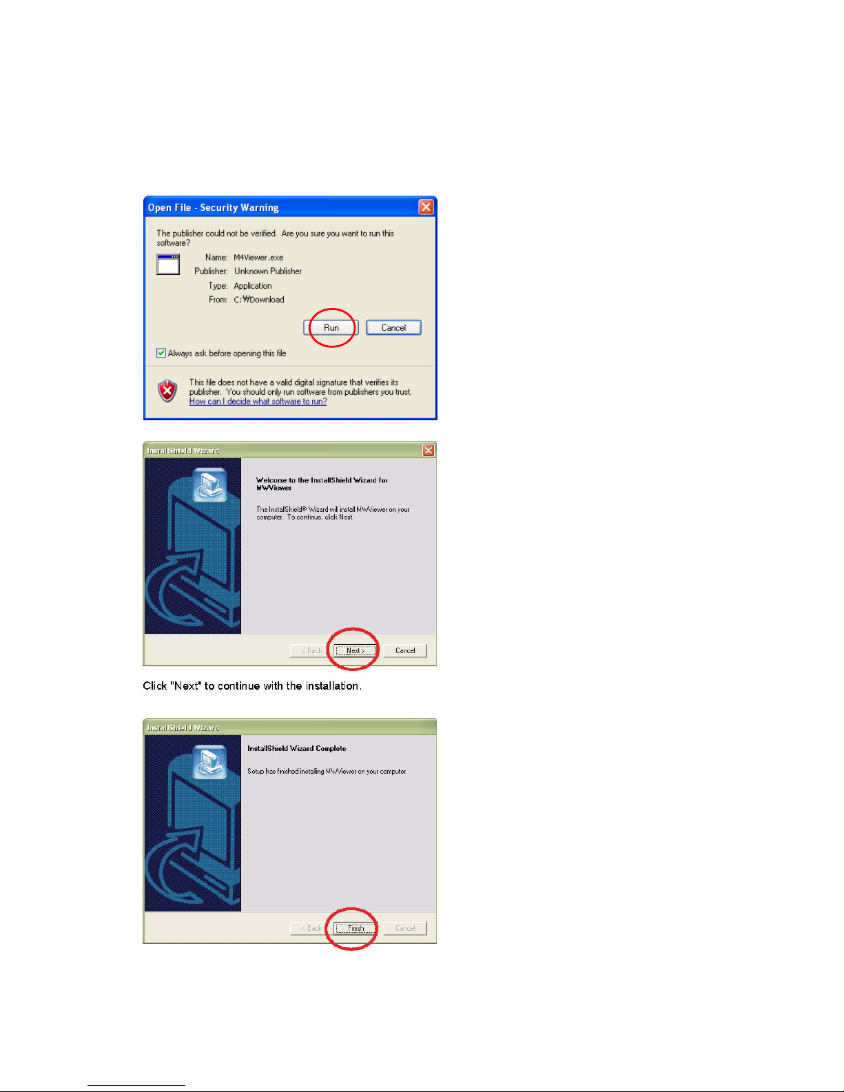
First you need to download M4Viewer.exe from the Web site www.networkipcam.com
. You can find
the link on the login page of the camera as shown below.
Save M4Viewer.exe on the computer's hard drive.
Page 23
23
Once the download is completed, you need to run the program by double-clicking it.
You may see the following message:
Click on "Run" to proceed with the installation. Click "Next" to continue with the installation.
Page 24
24
When you see the message above, you have successfully installed the ActiveX control.
Restart MS Internet Explorer and re-connect to the camera.
4.4 Homepage Options (MPEG4 Cameras)
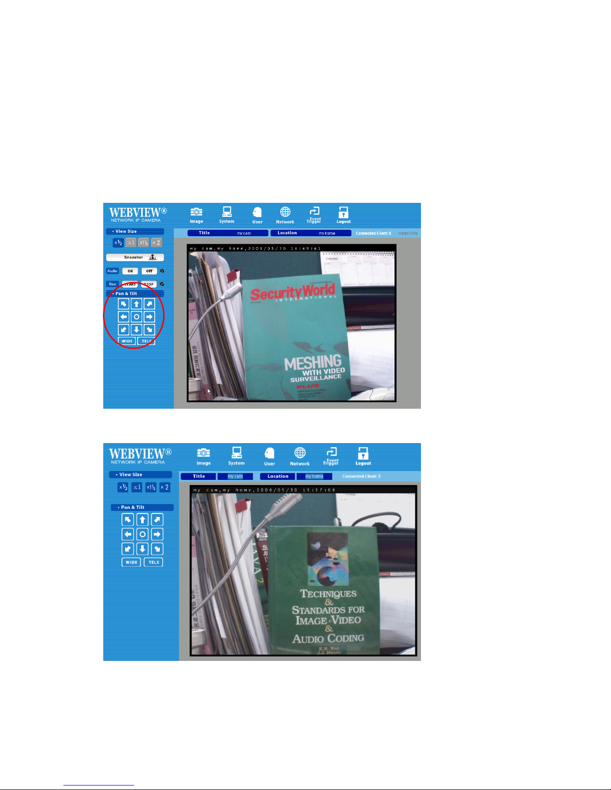
Once the login procedure is complete, you can view the Pro Series (MPEG4) Network Camera
homepage. Below is an overview of the different pages for the different models for both Java and
ActiveX.
ActiveX version
(Only Digital PTZ cameras and video servers show ‘Pan & Tilt’ control panel)
Java version : Snapshot, Audio and Recording are not supported in this mode.
Page 25
25
Video Size
You can select a viewing image size from 0.5 to 2. This function represents a digital zoom. It does not
change the physical resolution of the image. At high resolution (D1) the options "x1.5" and "x2" are not
available.
Audio
Select audio "on" for starting audio communication; select "off" to stop audio communication over the
network with the external microphone and speaker connected to the
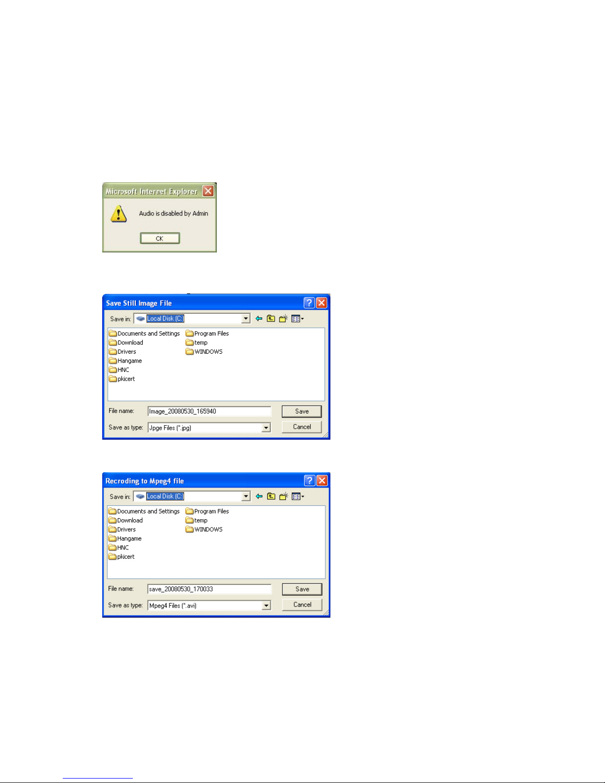
camera. If Audio is deactivated in the system settings of the camera,
clicking the "on" button results in the error "Audio is disabled by
Admin."
Save Snapshot
To save only one image, press "Save Snapshot" and then select a folder. The image is saved as a
JPEG file (with the default file name
composed of the date and time:
image_yyyy_mm_dd_hh_mm_ss.jpg).
Record Video
Users can save real-time images from the camera on a PC. Click "Start," then select the folder to save
the images in. (The image is saved as an
AVI file.) Once the camera starts to save
images, the green LED indicator will start
blinking. To stop saving, click "Stop" and
the LED indicator will stop blinking. You can
view a saved image with Windows Media
Player or Real-Time. For the initial playback
of a saved image, click "Install XviD."
NOTE: In Record Video mode, the video recording will be saved into a file different name every 20
minutes (for example: file name 2002_04_22_15_00, file name 2002_04_22_15_20…). If you assign
the file name in the first instance, not using default file name, the file name for the first 20 minutes will
be the assigned name but the names of subsequent files are composed as "user assigned name_
yyyymmdd_hhmmss.avi."
Page 26

26
Administrator Menu
This button is for accessing the administration menu. However, only the user who has authority as an
administrator can access the page with administrator’s ID and password (see Configuring
Administration Menu).
Logout
User can go back to the Login page by using the "Logout" button.
Connected Clients
Shows how many users are currently viewing the camera image.
Install XviD
In order to view the video, you have recorded in your computer, the XviD codec must be installed. If the
video does not play back correctly in Windows Media Player, you will need to install the XviD codec on
your system. The link on the camera homepage lets you download the XviD installer to your computer.
You then need to install the codec and restart your computer. After that, your computer will play back
the recorded camera
video with Windows
Media Player.
1. Download the file to the computer.
2. Run the installer and follow the
instructions on the screen.
Install Xvid
Page 27
27
Pan & Tilt (only certain models)
With these buttons, you can control the digital Pan Tilt Zoom of the camera. Click on "TELE" to zoom in
to the image and use the direction buttons to change the viewing area. Click on "WIDE" to zoom out to
see the entire image. This function is only available in the MPEG4 CMOS camera models.
5: Adjusting the Camera Lens
5.1 Adjusting the Focus
To get the finest image, adjust the lens focus according to your environment.
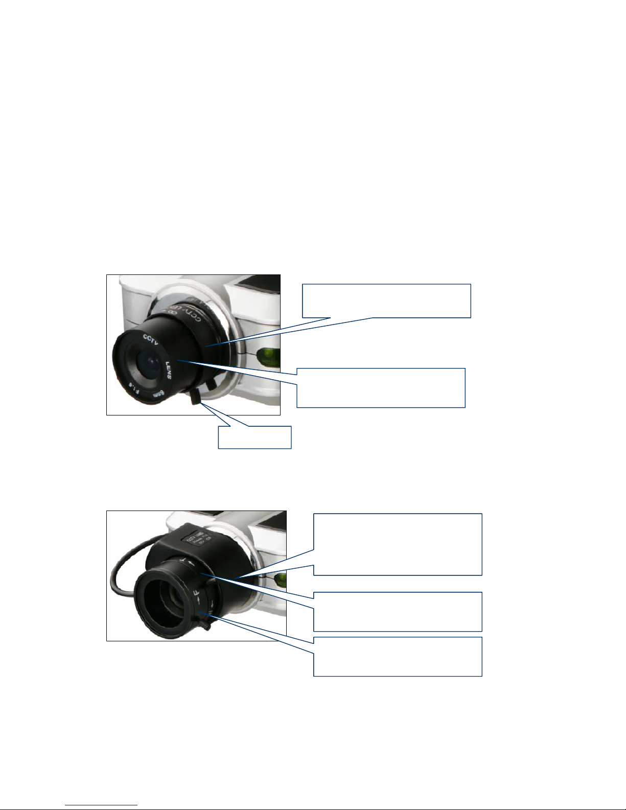
Standard Fixed Iris Lens
Before adjusting, turn the set screw counterclockwise, then turn the lens in either direction till you get
the most well-defined image edges while viewing the picture quality on your Web browser. When you
finish adjusting the lens, turn the set screw clockwise to fix it in place.
Auto-iris Vari-focal Lens
Before adjusting, turn the two set screws counterclockwise, then turn the wide-tele ring first to get the
best angle of view. After setting the angle of view by adjusting wide-tele ring, then turn the near-far ring
clockwise or counter-clockwise until you get the finest image.When you finish adjusting the lens, turn
the set screw clockwise to fix it in place.
Set Screw
Turn this part either clockwise or
counter-clockwise until you get
the best ima
g
e
Turn this part counter-clockwise
to unscrew and replace lens
T urn this p ar t counter-clockwise
to unscrew and replace lens.
Be sure to unfix the AI lens
connector from the camera body
first.
T urn this part either clockwise or
counter-clockwise until you get
the best an
g
le of view.
T urn this part either clockwise or
counter-clockwise until you get
the finest ima
g
e.
Page 28
28
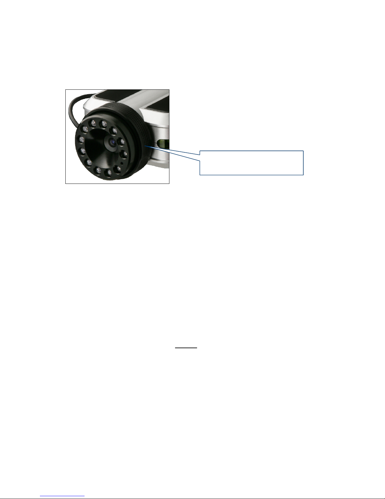
Night Vision IR Lens
NOTE: Do not force the lens beyond either the clockwise or counterclockwise limit. Also, a good level
of focus is normally achievable throughout several planes within the camera’s focusing spectrum.
Since optimum focusing is dependent upon the camera’s field of view, it is important to scan the
focusing plane from the closest to furthest perspectives before attempting any fine-tuning.
5.2 Replacing the Lens
The Pro Series Network Camera is designed with a CS mount. The lens supplied with your product
can be replaced with any standard C or CS lens, typically used within the surveillance industry. Follow
the instructions below to replace the supplied lens with any C- or CS-type lens.
1. Unscrew the camera lens by turning the lens counterclockwise (see above figure &
instruction).
2. For C lens only: Attach the new lens to a C-CS adapter.
3. Screw the new lens onto the camera. If applicable, adjust the iris according to the prevailing
light conditions.
4. Focus the lens as instructed above.
5. Reload your Web browser and monitor the results from the product homepage.
NOTE: The Night Vision Infrared Camera (MNC-L200IR MNC-W200IR) is equipped with a
special lens which cannot be replaced and must not
be removed.
Turn this part cautiously either
clockwise or counter-clockwise
until
y
ou get the finest image.
Page 29
29
6. Administrator Menu
You can control the configurations of the camera using the administrator tools, which can be accessed
only by an authorized user. If non-authorized users try gaining access, you may see a warning
message "You are not an administrator."
6.1 Overview of the Administration Menu
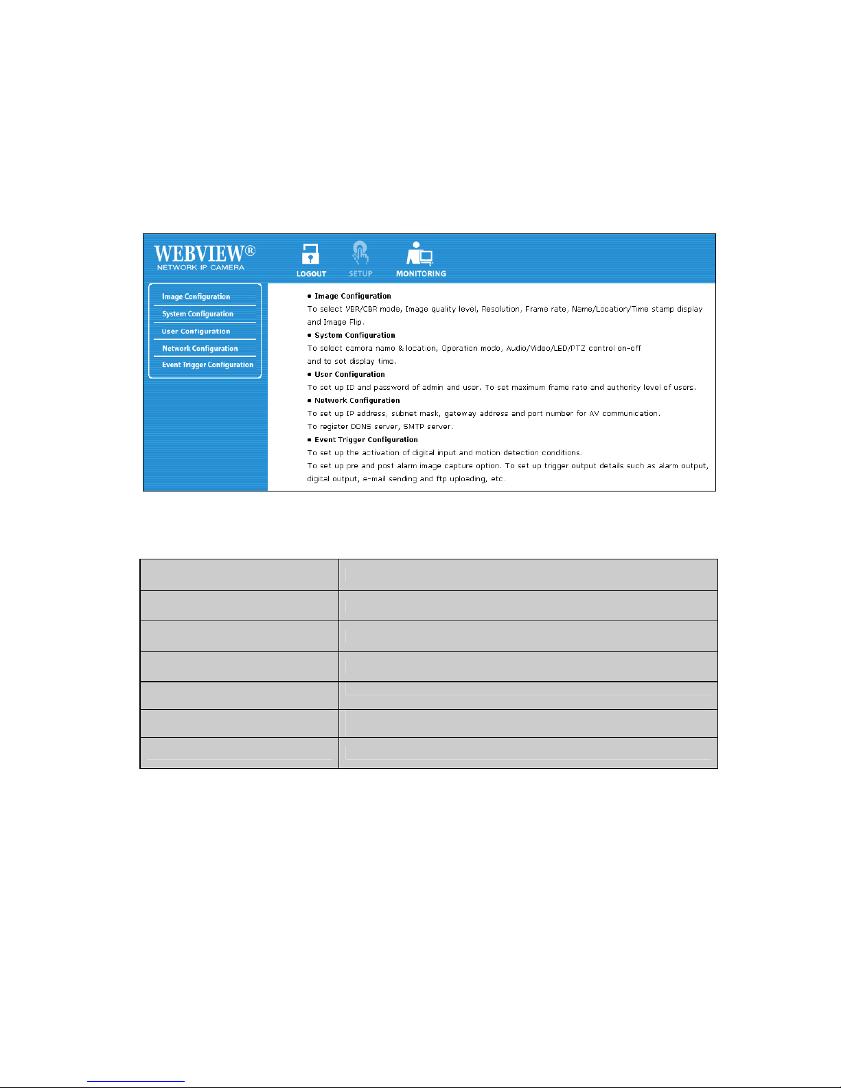
The table below provides a one-step overview of the Administrator Tools:
Image Configuration To Configure compression rate, image size, brightness, contrast, etc.
Network Configuration To configure camera IP, Web server port, image transfer port
User Configuration To configure user ID and password
System Configuration To configure the camera name, location and time settings
Event Trigger Configuration
To configure trigger condition, image capture option, trigger output, etc.
Wireless Configuration (wireless
models only)
To configure wireless parameters such as wireless mode, SSID,
encryption, etc.
Monitoring To go back to the monitoring page
NOTE: It is highly recommended that you change the administrato r password for your camera as soon
as possible to prevent unauthorized users from accessing the administrator menu. You can change the
administrator password in the User Configuration.
Page 30
30
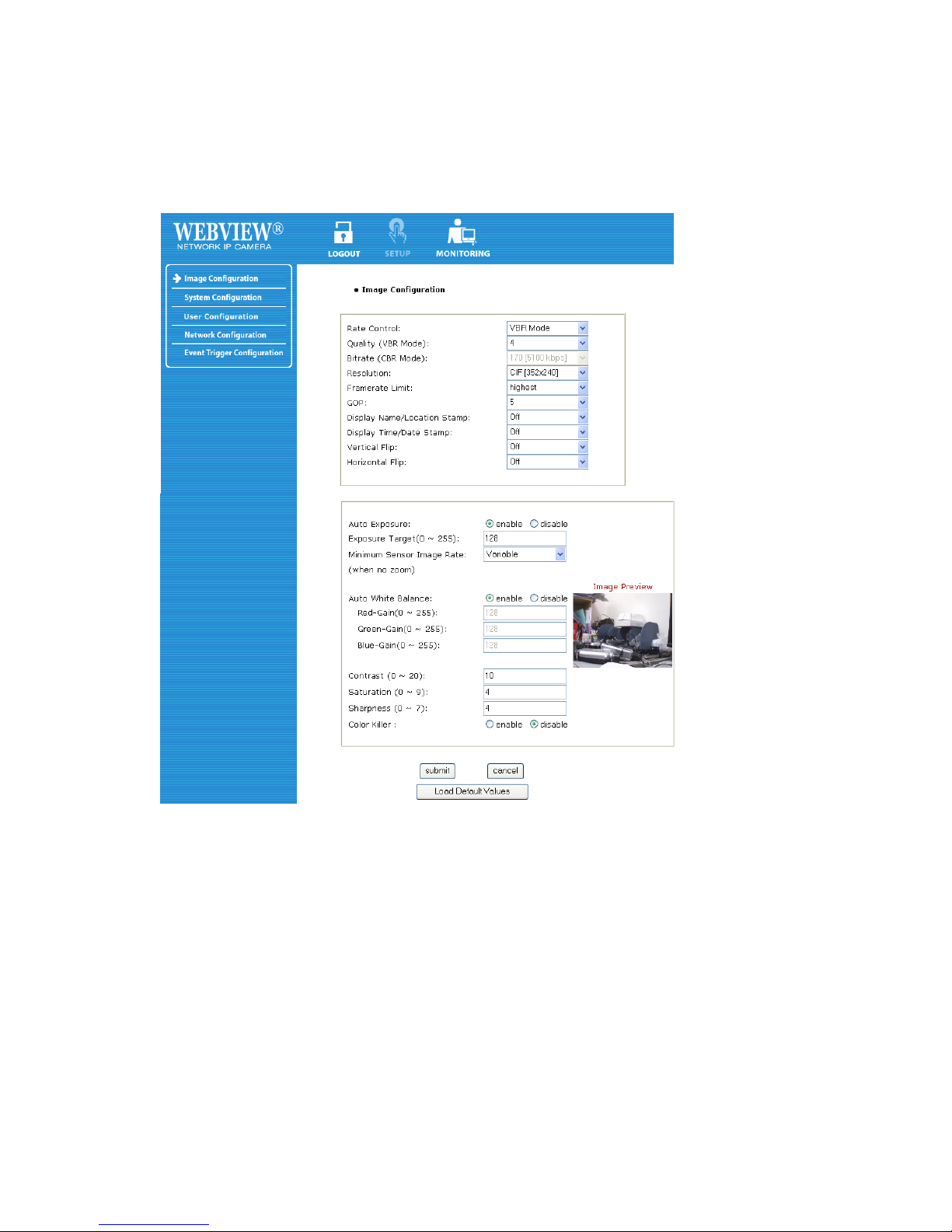
6.2 Image Configuration
Rate Control
The bit rate used in video encoding has a direct impact on the video quality and the bandwidth used to
stream video over the network. As opposed to constant bit rate (CBR), VBR files vary the amount of
output data per time segment. VBR allows a higher bit rate (and therefore more storage space) to be
allocated to the more complex segments of media files while less space is allocated to less complex
segments. The advantages of VBR are that it produces a better quality-to-space ratio compared to a
CBR file of the same size. The bits available are used more flexibly to encode the sound or video data
more accurately, with fewer bits used in less demanding passages and more bits used in
difficult-to-encode passages. CBR is the best option, if you have to limit the bandwidth available to the
camera; e.g., in order to save valuable bandwidth in busy networks.
Quality
This option is available when selecting the VBR rate control. Define the quality of the video output by
assigning a value ranging from "1" = best quality to "31" = worst quality. Good values are 4 or 5, as
they provide a good image quality at a relatively low network bandwidth usage.
Page 31
31
Bit Rate
Set the target bit rate of the encoding video. This option is available in CBR mode only. You can set
the bit rate values from 30 kbps up to 9000 kbps at an interval of 300 kbps. A higher bit rate ensures
higher quality of the live video at the expense of more network bandwidth usage. Controlling the
maximum bit rate is good for controlling the bandwidth used by the MPEG4 video stream. As the bit
rate is fixed, the frame rate and image quality can be affected adversely. The image quality can be
reduced if complex image material requires more bandwidth than allowed by the bit rate settings.
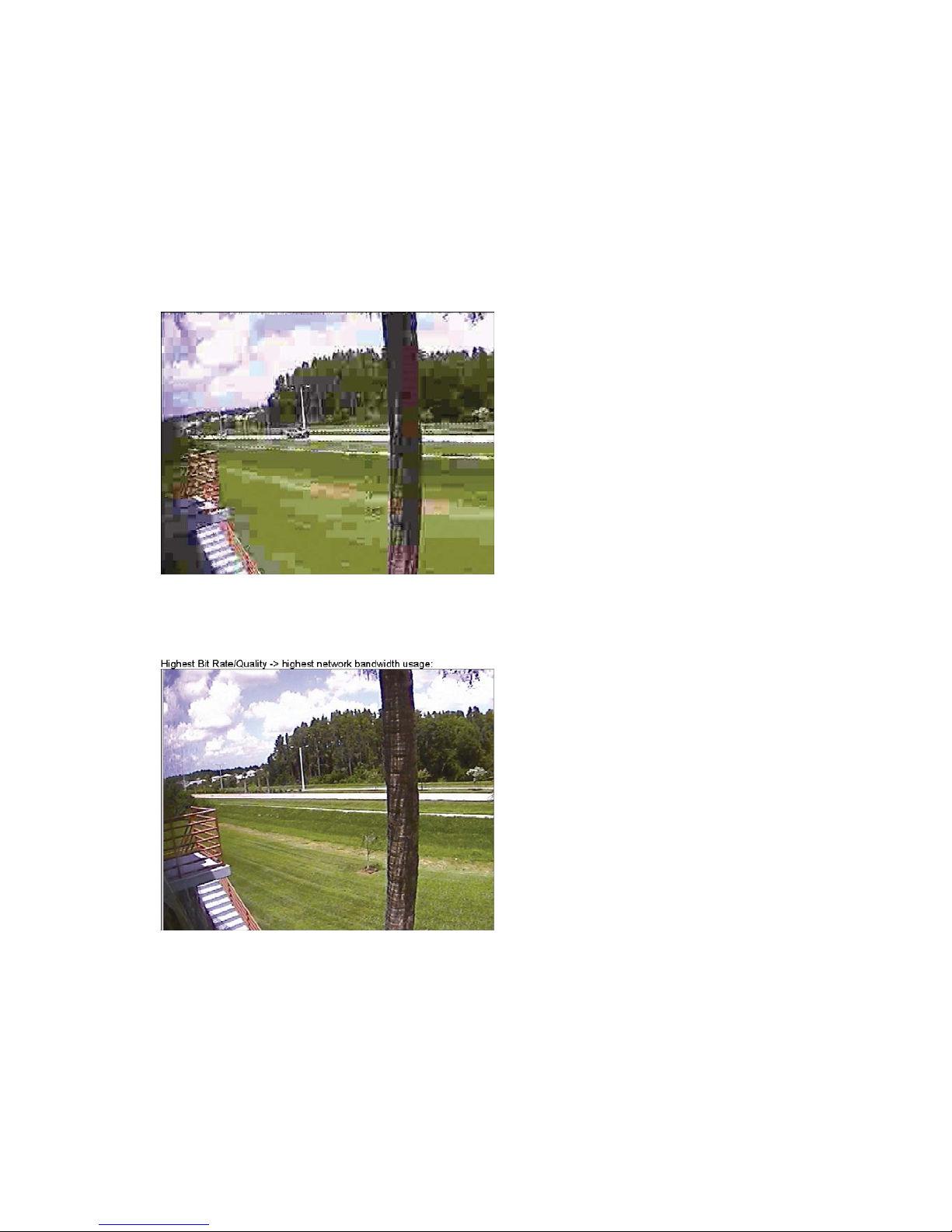
Lowest Bit Rate/Quality -> smallest network bandwidth usage
Above image illustrates the effects of lowering the video quality. You have full control over the amount
of bandwidth the camera can use, to the point where it becomes difficult to identify any objects in the
image due to heavy compression damage.
The effects of compression are minimal at the best image quality settings. The bandwidth usage of the
camera at this setting can be up to 8 Mbps.
Resolution
Select the resolution for output video. Pro Series CCD Network Cameras support three types of image
resolution. NTSC: D1 (720x480), VGA (640x480) and CIF (352x240); PAL: D1 (720x576), VGA
(640x576) and CIF (352x288). The Digital PTZ CMOS camera supports 720x480, 640x480, 352x240
and 320x240 pixel image resolution.
Page 32

32
Frame Rate
Select the frame rate according to your preference. The higher value of frame rate ensures
smoother video; but the higher the frame rate, the larger the network bandwidth usage.
GOP
Set the size of GOP (group of pictures). MPEG4 video stream consists of continuous GOP, and one
GOP consists of one "I" frame plus "P" frames. This value equals the period of one "I" frame. The more
the GOP size, the less network bandwidth will be occupied. Higher GOP values will save considerable
network bandwidth, but at the expense of image quality. The default value is "5" and works fine for
most applications.
Display Name/Location Stamp
Select "On" to display the camera name and location at the top of the transmitted images.
Display Time/Date Stam p
Select "On" to display the camera time and date at the top of the transmitted images.
Video without Name/Location Stamp and Time/Date Stamp
Video with Name/Location Stamp, but without Time/Date Stamp
Video with Name/Location Stamp and Time/Date Stamp
Vertical Flip and Horizontal Flip
Use these options in order to flip the video horizontally and/or vertically.NOTE: These options only
affect the live image shown in the Web browser, but not any videowhich the camera has uploaded to
an FTP server or has sent out via e-mail. For ceiling mount installation, use the top tripod mounting
hole instead of the image flip option.
Page 33
33
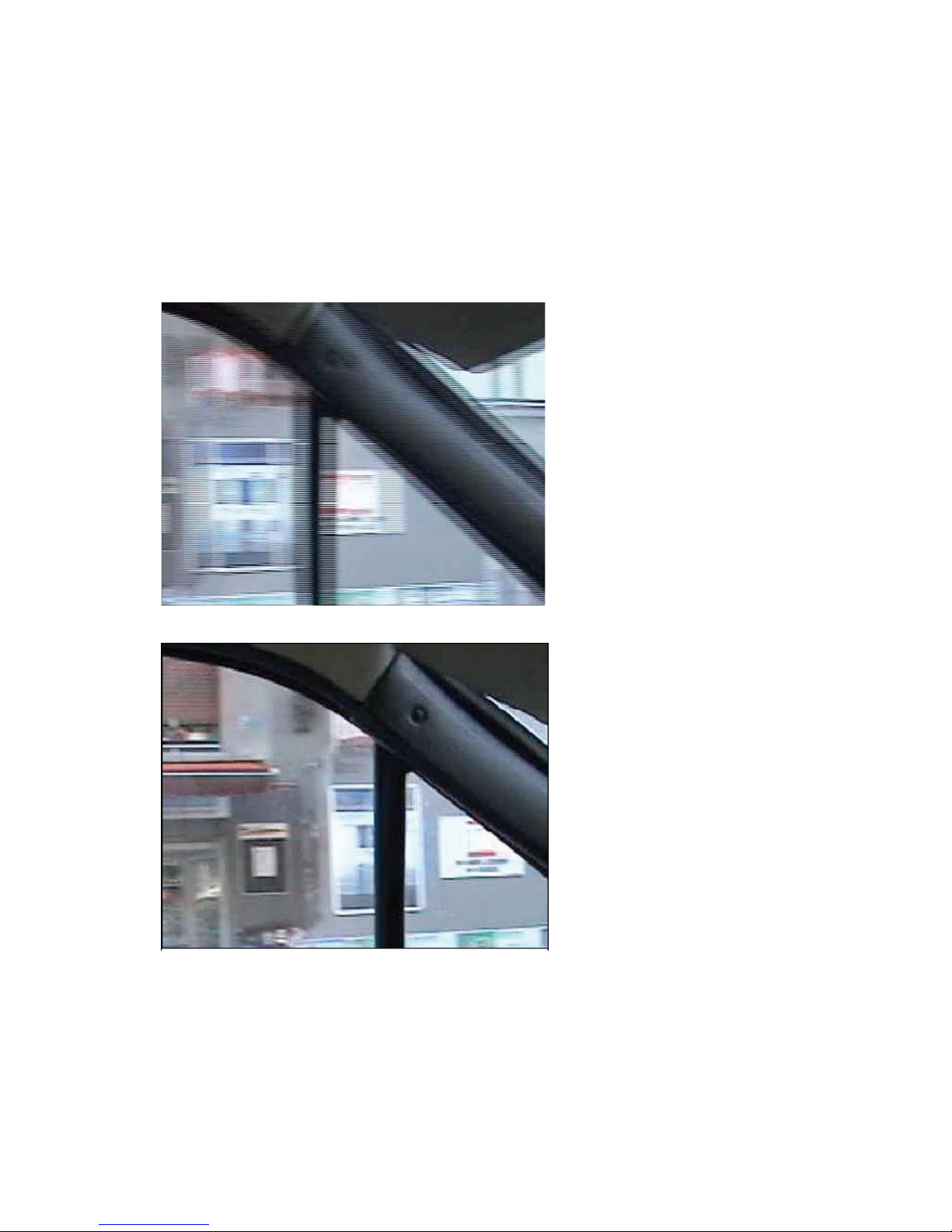
De-Interlace
Interlaced video is composed of two fields that are captured at different moments in time. When
displayed on a typical computer screen, interlaced video frames will exhibit motion artifacts when both
fields are combined and displayed at the same moment (today's computer screens are progressive
scan monitors which display the image line by line from top to bottom without interlacing) These motion
artifacts are visible in the form of horizontal lines. See below figure;
De-interlacing reduces the effects of interlacing through methods of interpolation. See below:
NOTE: De-interlacing is only active for ActiveX / MS Internet Explorer. Java does not support it.
Brightness
Set the image brightness. A higher number equates to brighter video (input 0 to 255).
Page 34
34
Contrast
Set the image contrast in the range of 0 to 200.
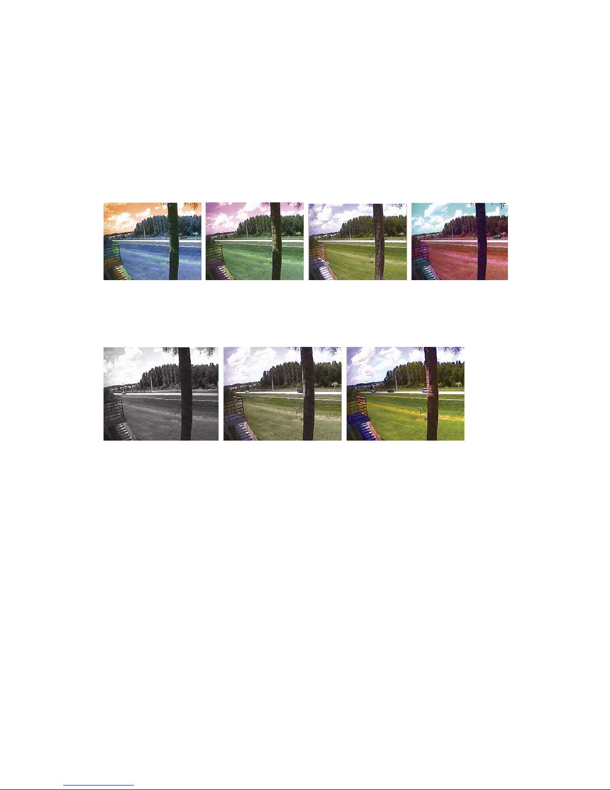
Hue
Most sources of visible light contain energy over a band of wavelengths. Hue is the wavelength within
the visible-light spectrum at which the energy output from a source is greatest. Normally there is no
need to change the default value (8), but if you wish to experiment with different hue values to achieve
different effects, the camera offers 15 values to choose from.
Examples of different Hue Values (from left to right: 0, 4, 8, 10). Actual results may vary, depending
on the camera model.
Saturation
Set the saturation value of images. Higher saturation values generate deeper colors (input values
ranging from 0 to 255)
Examples of different Saturation Values (from left to right: 0, 128, 255). Actual results may vary,
depending on the camera model.
Color Killer
Enabling this will switch the image into gray (monochrome) format. Disabling this option sets the
images at their original color.
Load Default Values
Set the image configuration as default values.
Below options are only for digital PTZ IP cameras. (Model : MNC-L100M20 / MNC-W100M20)
Auto Exposure
Enable or disable the Auto Exposure. The exposure target can be used to define the brightness of the
image. 128 is the default value. The higher the value, the brighter the image.
Minimum Image Sensor Rate
Here you can define the minimum frame rate of the image sensor. "Variable" is the default value and
best suited for most applications as it adjusts the frame rate according to the available light levels while
providing the best possible image quality.
Page 35
35
Auto White Balance
Enable or disable Auto White Balance. If set to "disable," you can manually control the amount of red,
green and blue color in the input fields below.
Saturation
Set the saturation value of images. Higher saturation values generate deeper colors (input values
ranging from 0 to 9).
Sharpness
This value lets you control the sharpness of the image. Lower values generate a smoother image;
higher values generate a crisper image.
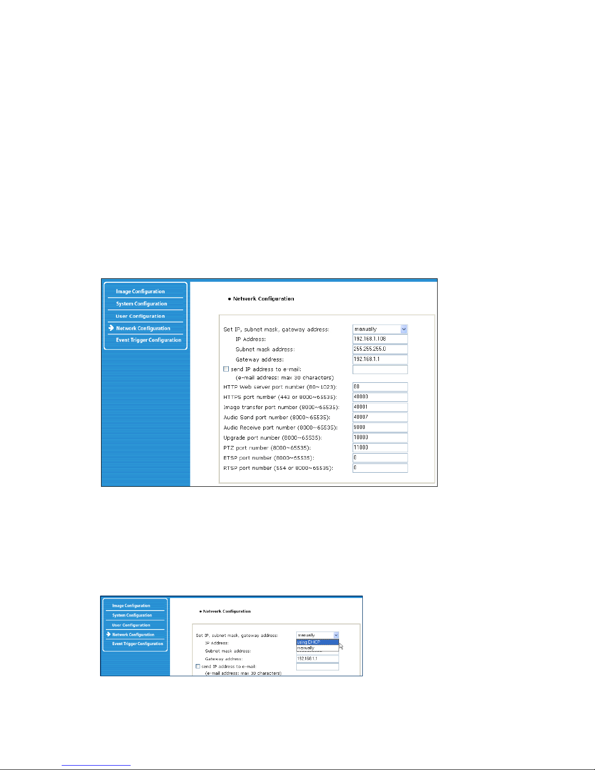
6.3 Network Configuration
This screen defines the network type and addresses of the camera. Here you can configure the
camera’s IP address, the DNS server address and the SMTP server IP address.
Set IP address, Subnet Mask, Gateway Address
To set the IP address, subnet mask and gateway address manually, select "manually" in the combo
box. If you have any trouble configuring network system information, contact your network
administrator. Knowledge about IP addresses and TCP/IP is required for the configuration task.
Set DHCP
When selecting "using DHCP," the IP address, subnet mask address and gateway address are being
obtained from a DHCP server. Users in a local network area may check the IP address through IP
Installer.
Page 36

36
NOTE: If you select "DHCP," you may see the rebooting message "Now the Network Camera is
rebooting to apply the changes..." on the Web browser. After completion of the reboot, the Status LED
blinks once per second. (Confirm that the Operating Status LED blinks after selecting "DHCP" and the
rebooting process to ensure your new setting took effect.) To select DHCP, you must have a DHCP
server in the network. Otherwise, the IP address will be rebooted automatically as the previous IP
address. It can take about 4 minutes for booting. After rebooting, re-enter the previous IP address. You
may see the fail message from the "Network Configuration" page.
Send an IP address to Email
To send camera system information (camera name, camera location, DHCP IP address), click on a
text box and enter your e-mail address. (You should configure your SMTP server information first.)
Web Server Port Number
To set the port number for the Web server. (The default port number is "80"; users can select from
80 to 1023.)
HTTPS Port Number
The camera's SSL encryption uses port 443 by default. You can adjust the value.
Image Transfer Port Number
To set the port number for the video/image transfer. (The default port number is "40001"; users can
select from 8000 to 65535.)
Audio Send Port Number
To set the port number for the audio transfer to the connected camera client. (The default port
number is "40008" and users can select from 8000 to 65535.)
Audio Receive Port Number
Set the port number for the receiving audio from a connected camera client. (The default port
number is "40007"; users can select from 8000 to 65535.)
Upgrade Port Number
To set the port number for upgrading firmware. (The default port number is "9000"; users can
select from 8000 to 65535.)
PTZ Port Number
NOTE: PTZ control is not available on these Pro Series Network Camera models.
ETSP Port Number
To set the port number for ETSP (Event Trigger Setting Saving Program). The default is "11000";
users can select from 8000 to 65535. Refer to section 9 for instructions on the ETSP client.
RTSP Port Number
RTSP stands for Realtime Streaming Protocol and allows RTSP enabled video playback clients such as
VLC Media Player or MPlayer to play back the live video from the network camera. For more information
refer to section "RTSP Video Playback". We recommend using the default value " 554".
Page 37
37
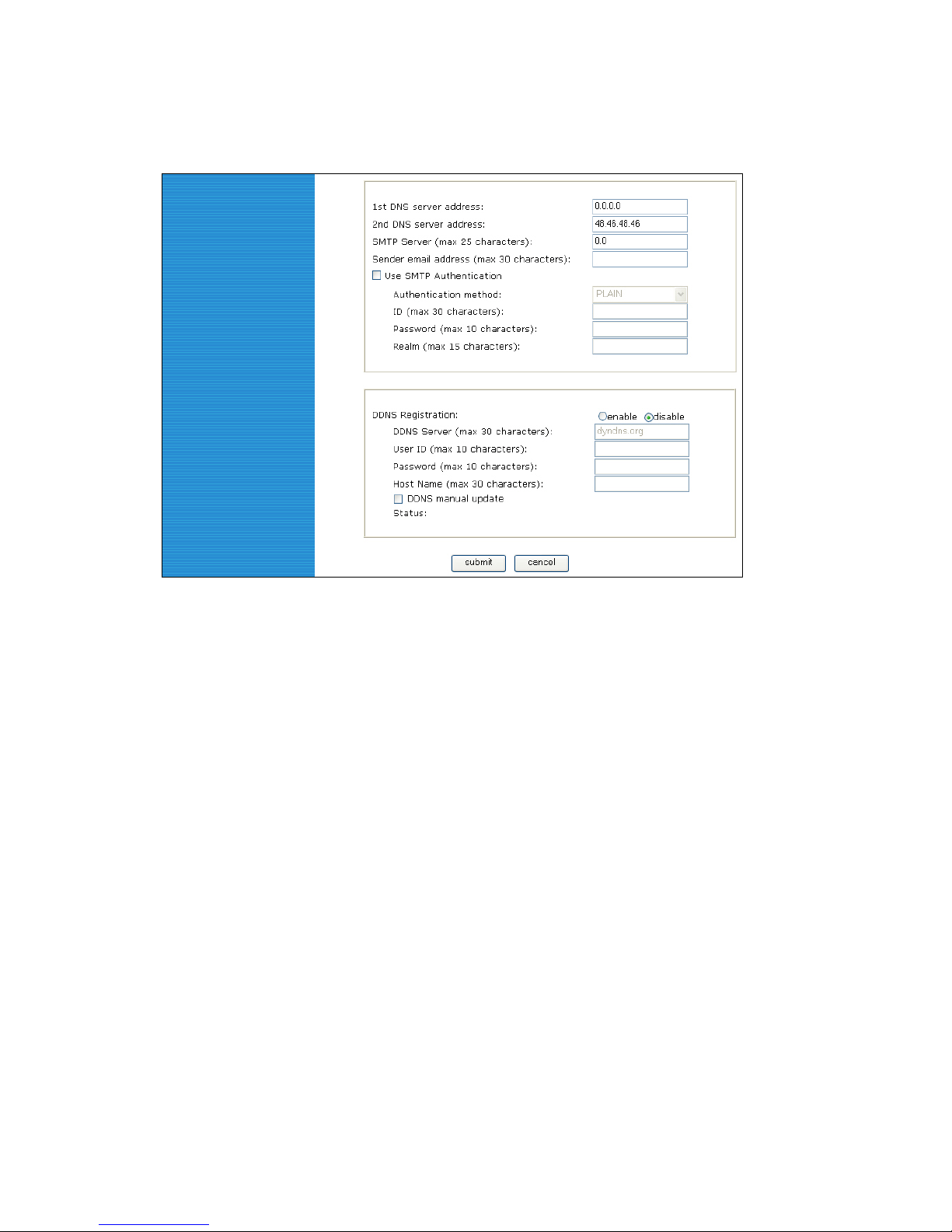
1st, 2nd DNS Server Address
To map between an IP address and domain name, you should enter your DNS server address. If a
user sets the DNS server into the camera, users can configure the SMTP server, FTP server and NTP
server with its domain name.
NOTE: A DNS (domain name system) is for mapping between an IP address and domain name. Every
network device in the world has its IP address for connecting to the Internet. And the device is to be
connected not with its domain name but with its IP address. Ordinary users may not be familiar with IP
addresses, but know the domain names. If a user accesses a certain network device with its domain
name, the DNS server translates the domain name into an IP address of the device and replies to the
user with the result.
SMTP Server
Enter the SMTP server IP address or hostname here to send camera system information by e-mail.
You should configure this first to get camera system information by e-mail.
Use SMTP Authentication
If you need user authentication for using the SMTP server, check the box and enter your ID,
password and realm for your SMTP server. (The camera’s SMTP authentication is supporting the
"LOGIN" method.)
- Authentication method: Choose the SMTP authentication method.
- ID: Enter the user ID for SMTP authentication.
- Password: Enter the user password for SMTP authentication.
- Realm: Enter the realm for SMTP authentication.
DDNS Registration
To register the camera to the DDNS (dynamic domain name system) server, check the "enable" box. A
Page 38
38
dynamic IP address complicates remote access since you may not know what your current WAN IP
address is when you want to access your network over the Internet. The solution to the dynamic IP
address problem comes in the form of a dynamic DNS server.
ID, Password
Enter the ID and password to find the registered camera on the DDNS server.
Hostname
Enter the hostname to find the registered camera on the DDNS server. NOTE:
Enter a full domain name (such as "mynetworkcam.dyndns.org").
DDNS Manual Update
You can update the DDNS server manually.
CAUTION: Repeated use of the function may lead to the blocking of your DDNS domain name.
Status
To show the status of successful access to the DDNS server.
Submit
Save the information.
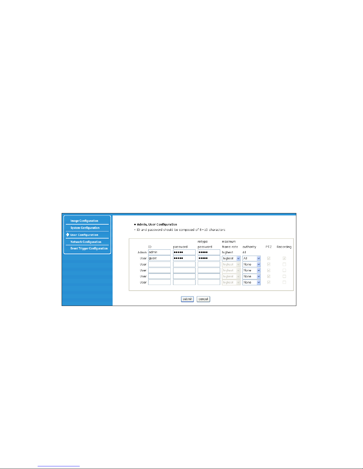
6.4 User Configuration
This screen is used to define and configure user accounts for camera access.
ID
User Name must be between 5 and 10 characters.
Password
Password must be between 5 and 10 characters.
Maximum Frame Rate
You can define the maximum frame rate this user is allowed to receive. This function can be useful if
you allow public access to your camera; e.g., you may have the camera live image integrated into an
HTML page on your Web site, but want to keep the users from consuming all of the available
bandwidth. Reducing the maximum frame rate allows you to do that. Example: The frame rate in the
image configuration is set up as 25. The maximum frame rate for the guest user account is set to 1.The
maximum frame rate for a second user account (e.g., admin) is set to fastest. If the admin user
accesses the camera, the frame rate shown in the Web browser is 25, but the guest user only views
the video at 1 fps (frame per second).
Page 39
39
Authority
None – no access to the camera is possible.Viewing – access to the live image, but no access to the
administrator menu. All – access to the live image and access to the administrator menu.
PTZ (Only Digital PTZ Camera models)
Activate this option if you wish to grant the user authority to use the Pan-Tilt-Zoom control on the
camera live video page.
Recording
Allow or restrict the ability to record video from the camera live video page. Leave this option
unchecked if you do not want the user to record any video.
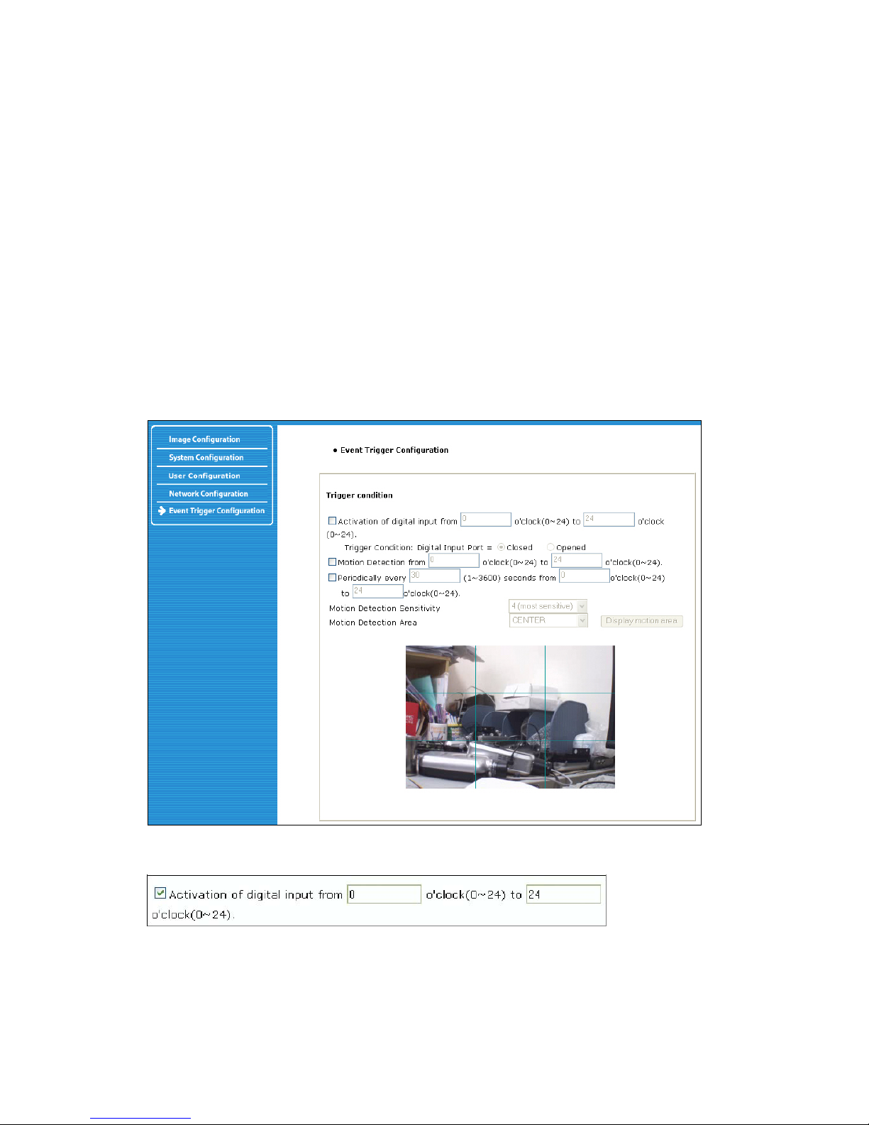
6.5 Event Trigger Configuration
This screen is used to receive captured video through e-mail or an FTP. You may also connect
external devices, such as an infrared sensor or alarm sensor to use with the provided terminal block.
(Refer to Appendix F: The I/O Connector)
Trigger Condition
This is to select options for sending an event signal to the camera.
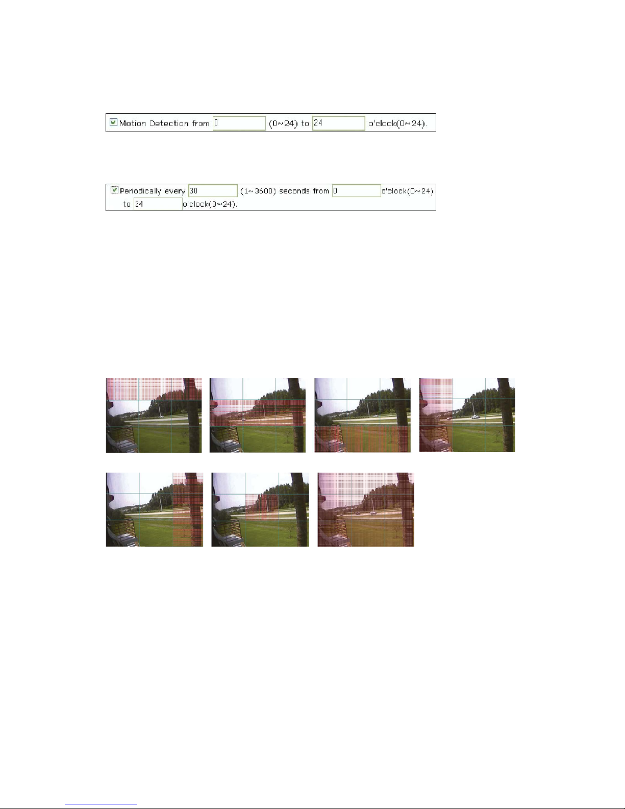
The camera receives an event signal from external devices such as an infrared sensor. You can define
the time (international 24h time format) in which the camera "listens" for incoming signals.
Page 40
40
Activate the camera's internal motion detection using this option. The camera does a real-time
frame-by-frame comparison of the image material and can trigger an alert if it detects motion. The
camera does not have an IR motion detection sensor. It relies on a frame-by-frame comparison, and,
therefore, the internal motion detection cannot be used at night when no light is present.
This activates a timer-based event. Values from 1 to 3600 seconds are valid. You can define the time
(international 24h time format) in which the camera's timer is active to trigger an output event.
Motion Detection Sensitivity:
This is to configure the level of motion detection sensitivity. The level is composed of five levels, from 0
to 4. Value 0 is the least sensitive setting. At this setting, the camera may "overlook" a lot of motion.
Value 4 is the most sensitive setting. At this setting, the camera will likely cause a lot of false alarms
because the tiniest movement – even the video compression – which can create compression artifacts,
can trigger an alert. Values 1 - 3 are more suited for real-life applications. Experiment with the different
settings to find the right level of sensitivity for your application.
Motion Detection Area:
This is to configure the motion detection area in the images. If you select "Motion Detection Area"
type in the combo box and click "Display motion area," then you can see your setting of "Motion
Detection Area" graphically as shown in the figures below.
Top Middle Bottom Left
Right Middle_Middle All Set
CAUTION: It is not recommended that the motion detection function be used for security purposes. To
perform security surveillance for the protection of high-value goods, it is suggested that infrared
sensors or other insurance-approved sensors be used (and connected to the camera to make use of
the event output options). It should also be mentioned that the motion detection delivers better results
at lower image resolutions.
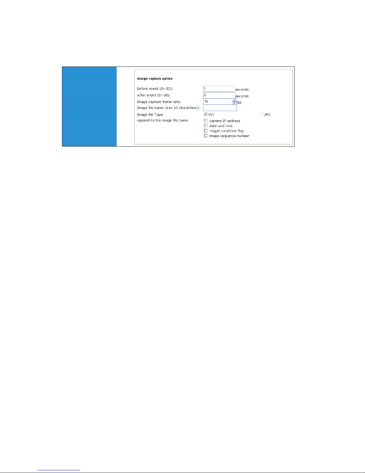
Image Capture Option
This is to configure image capture options when an event is triggered. When an event occurs, you can
get the pre-event and post-event images by setting "Before event" and "After event."
Page 41
41
Before event:
You may set the starting time to capture an image before the event is triggered. (Input limitation is
from 0 to 30 seconds.)
After event:
You may set the finishing time to capture an image after the event is triggered. (Input limitation is
from 0 to 30 seconds.)
Image capture frame rate:
Set from 1 to 15 fps when an image is being captured.
Image file name:
You may designate the image file name to send e-mail or FPT after an image is captured. All
captured images are saved as .avi files (for example: Filename.avi).
Image file type:
You can choose between two options. AVI means that the camera transmits a video file. JPG
means that the camera transmits a series of single JPEG images.
Append to the image file name:
You may add information to the image file name.
9 Camera IP address (example: filename_192.168.1.19.avi).
9 Date and time (example: filename_20020218150030.avi).
9 Trigger condition flag: When selecting "Activation of digital input port," "D" may be added to
the image file name (example: filename_D.avi); when selecting "Periodically every…," "P" is
added to image file name (example: filename_P.avi).
9 Image sequence number: With this option, you may classify a file with the same name with
consecutive numbers from 000 to 999 (example: When you designate file name as
"camera" and select "Image sequence number," the file name appears as camera001.avi,"
"camera002.avi" and so on through "camera999.avi").
Image Capture option limitation
The configuration for the image capture option affects memory capacity. If the configuration uses
excessive memory, the warning message “Not enough memory…" will display. The total image capture
frame rate must be no more than 120 fps due to memory size. (Before event time + After event time) x
(Image capture frame rate) must be under 120.For example, if “Before event time" is 3 seconds, “After
event time" is 2 seconds and “Image capture frame" is 3 fps, the total image capture frame rate is (3 +
2) x 3 = 15 fps.
If a warning message appears, reduce the v alue of the option.
Page 42
42
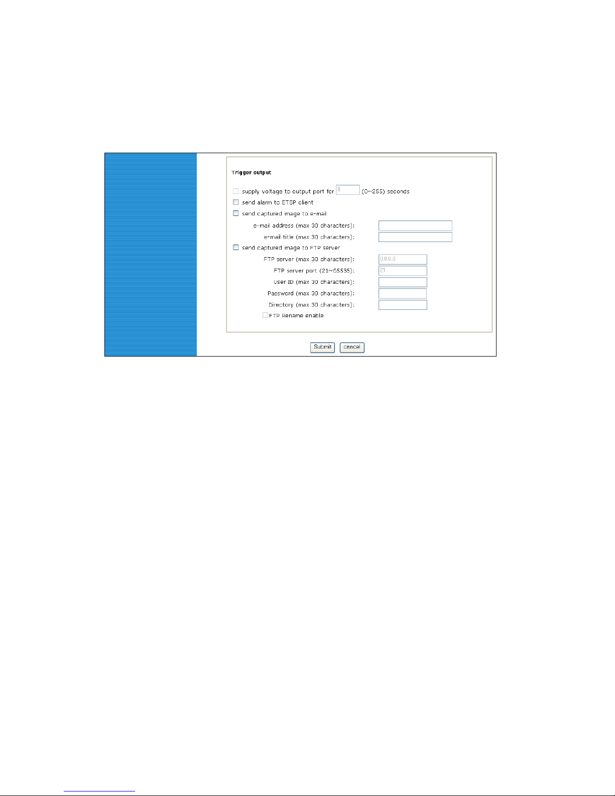
Trigger Output
This is to configure digital output states and control script. The Pro Series Network Camera sends
captured images via e-mail or an FTP server when connected external sensors detect events.
Supply voltage to output port for xxx seconds.
This is to supply voltage to the output port when events are triggered. (This option is only activated
when you select the "Activation of digital output" option in the "Trigger Condition" section.) During
the activation period, which you can specify in seconds, the camera provides power to the GPIO
connector in pins 3 and 4 – see Appendix F.
Send alarm to ETSP client:
By checking the box, an alarm will be sent to the ETSP client when the events are triggered. Refer
to Section 9 for instructions on the ETSP client.
Send captured image to e-mail:
This is to designate a person to receive captured images via e-mail through the SMTP server. You
may configure the SMTP server and e-mail address as desired.
Send captured image to FTP server:
This is to send captured video from the camera when an event is triggered. Enter an FTP server IP
address, user ID and password, and select a directory to save video.
Page 43
43
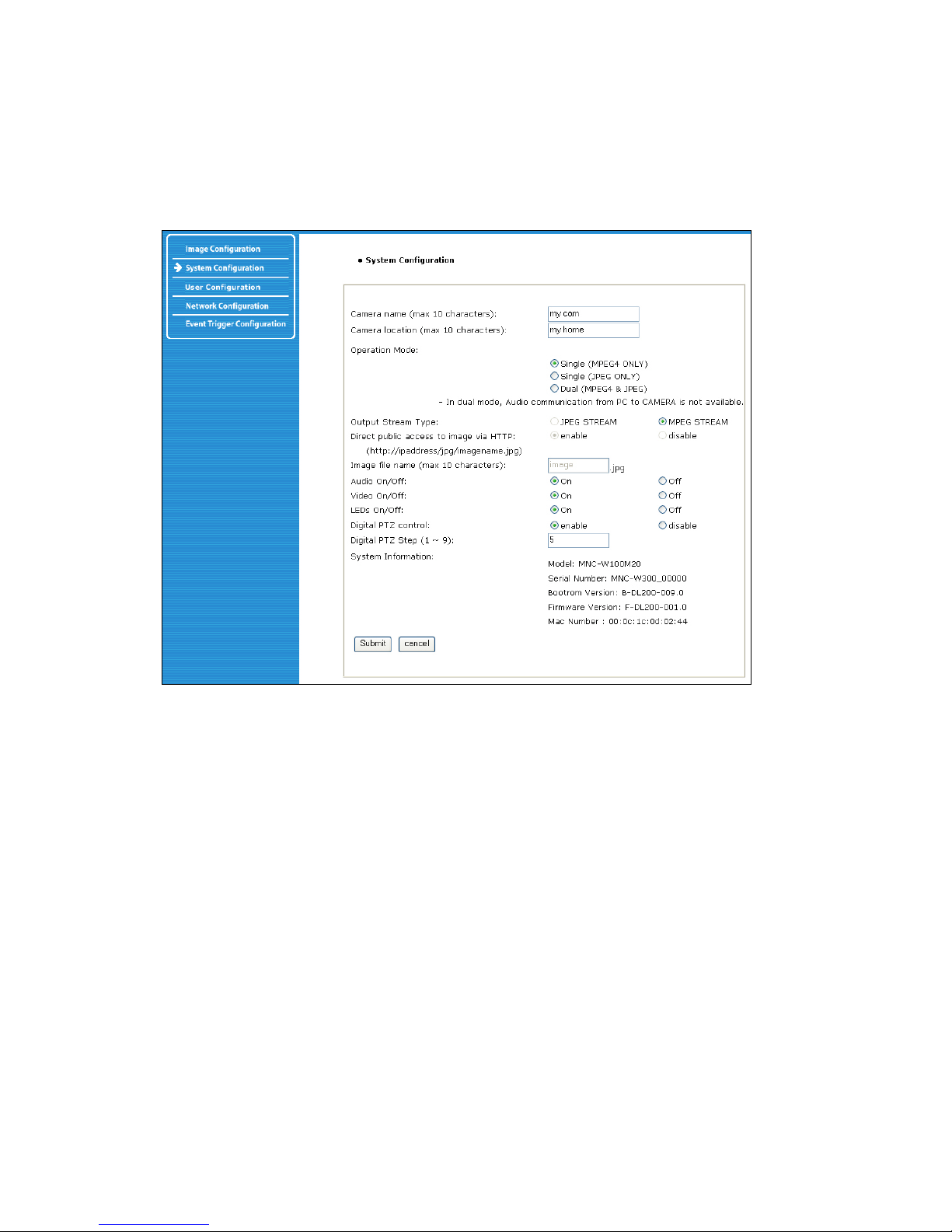
6.6 System Configuration
This screen is used to configure camera name, location, operation mode and system information, as
well as time configuration for the camera.
Camera Name
Define the camera name, maximum of 10 characters.
Camera Location
Define the camera location, maximum of 10 characters.
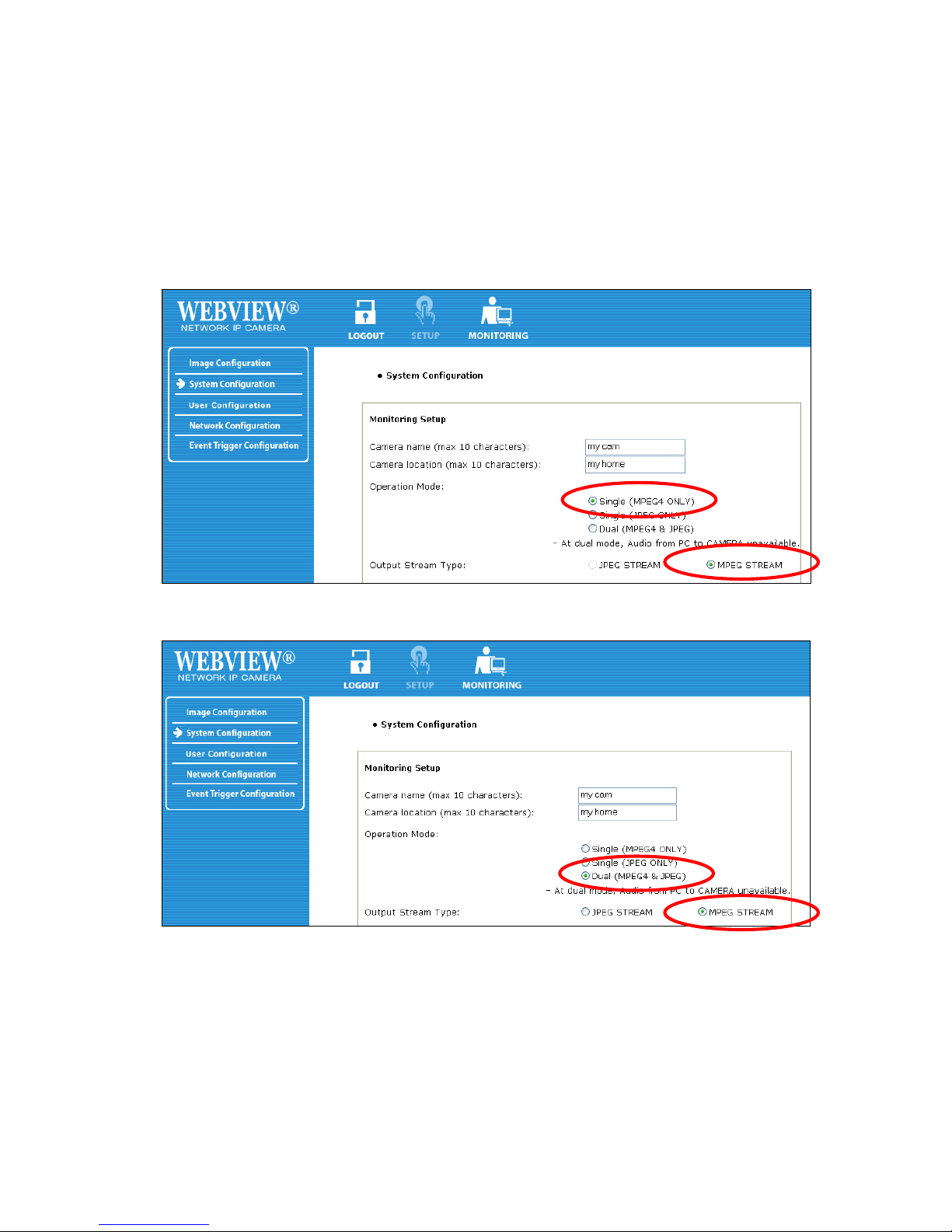
Operation Mode and Output Stream Type
There are three operation modes for the camera: Single (MPEG4 Only), Single (JPEG Only) and Dual
(MPEG4+JPEG). In Dual mode, the camera can encode and transmit both MPEG4 and JPEG images
simultaneously over the network, whereas in Single mode only MPEG4 or JPEG video will be
encoded and transmitted. In Dual (MPEG4+JPEG) mode only, the Output Stream Type is selectable
between JPEG stream and MPEG4 stream. The stream type defines which type of data is sent to
users connecting via a Web browser. Also in Dual mode, audio communication from PC to camera is
not available, whereas in Single mode (which uses MPEG4 only) bi-directional audio communication
is available.
Direct Public Access to Image via HTTP
The purpose of this function is to allow your video surveillance program to access the camera image
even if the software offers no support for MPEG4 cameras.JPEG images are only transmitted in Dual
(MPEG4+JPEG) and Single (JPEG Only) mode and are accessible through http://camera IP
(URL)/jpg/imagename.jpg. In Single (MPEG4) mode,this function is not activated. When "enabled" is
selected, anyone can access the camera imagewithout entering a username or password (example:
http://192.168.1.221/jpg/image.jpg). When "disable" is selected in order to view the image, a username
Page 44
44
and password must be given (example: http://guest:[email protected]/jpg/image.jpg).
Image File Name
This option is used to for accessing the JPEG images with ".jpg" extensions. The file name
should be less than or equal to 10 characters.
Audio On/Off
Activate or deactivate the camera's audio function. This option can be important in situations in
which, by law, you are not allowed to do video surveillance that includes audio and you are required
to install a camera without audio support.
Video On/Off
This option is used to stop sending video temporarily from your camera over the Internet or
network; thus, when you click "Off," your network camera no longer sends video. (Factory default
is Video "On.")
LED On/Off
In LED "On" mode, LEDs on your camera operate as described in LED Section 2.2 on Page 7. When
you activate LED "Off" mode, then all LEDs are turned off as if your camera were inactive, but the
camera is still sending video and audio over the network or Internet. This function can be useful if you
want to trick a suspected thief into believing that the camera is turned off while, in fact, you are
recording all of his/her actions.
Digital PTZ control (only for digital PTZ c a mera models)
Enable or disable the Digital PTZ control option on the camera homepage. This option is only
available for the MPEG4 CMOS cameras models MNC-L100M20 and MNC-W100M20.
Digital PTZ Step (1 ~ 9): (only for digital PTZ camera models)
You can define PTZ step size here. Value 9: 12 steps between maximum zoom out and maximum
zoom in. Value 1: 120 teps between maximum zoom out and maximum zoom in.This option is only
available for the MPEG4 CMOS cameras models MNC-L100M20 and MNC-W100M20.
System Information
This is to check system information for the camera. You may see the model name, serial number,
MAC number, BootRom and Firmware version (see Appendix E: Updating Firmware).
Page 45
45
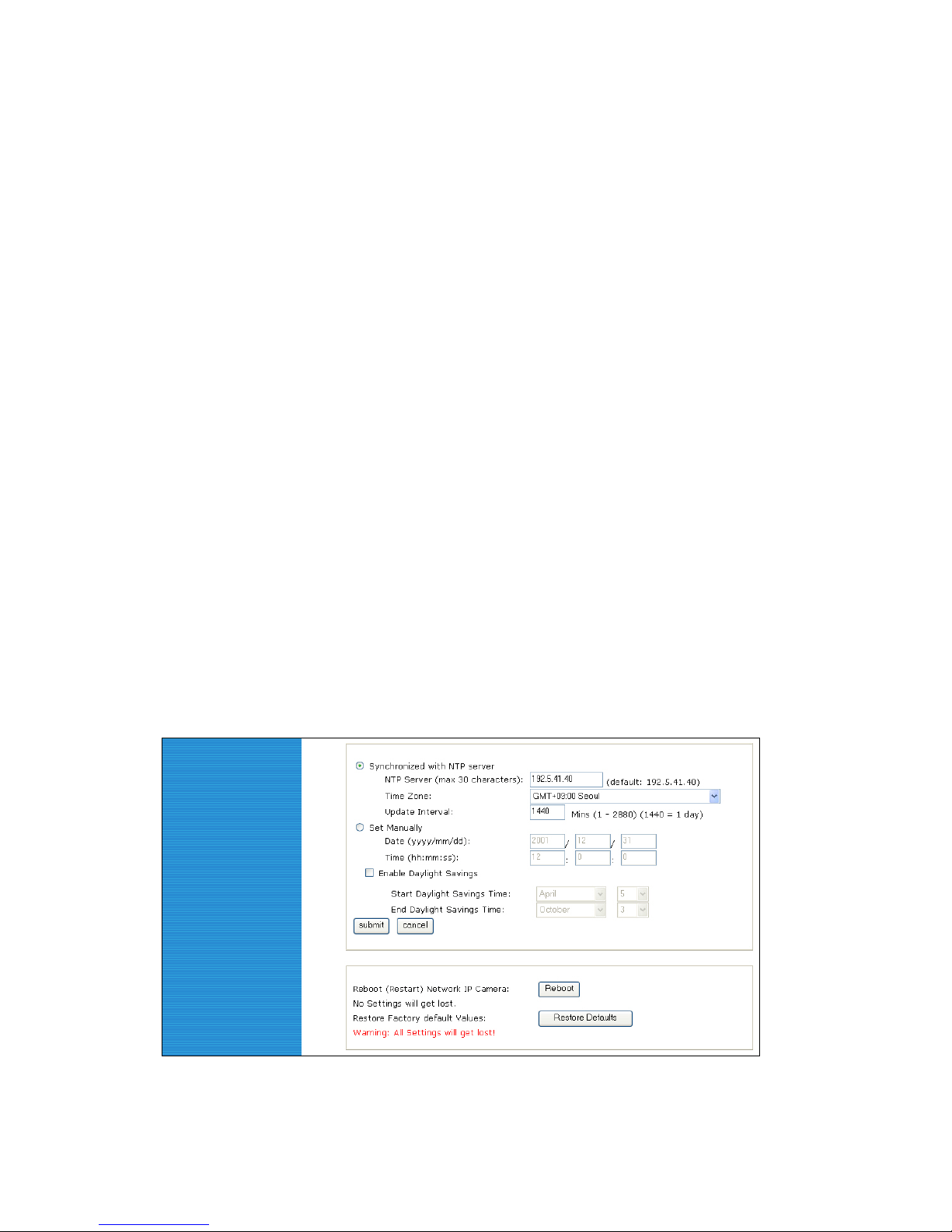
Synchronized with NTP Server
The camera automatically configures the date and time through the NTP (network time protocol) server.
The NTP server is based on Greenwich time. Select the NTP server, IP address and time zone to set
the date and time automatically, then click "submit."
NOTE: If this procedure doesn’t work, it could be due to a network error. Select another NTP server
and IP address or set the date and time manually. Once the date and time configuration is set, you
don’t have to configure it again.
9 . NTP Server: The standard public or private NTP server IP address.
9 . Time Zone: Select the appropriate time zone as per the camera location.
9 . Update Interval: The update time interval for updating/synchronizing the camera time with
the NTP server.
Set Manually
Enter the date and time manually, then click "submit."
Enable Daylight Saving
Enter the dates you want to start/end Daylight Saving Time.
Reboot (Restart) Network Camera
This option will reboot or restart the camera. Your settings will not be lost.
Restore Factory Default Values
This option will restore the default factory values.
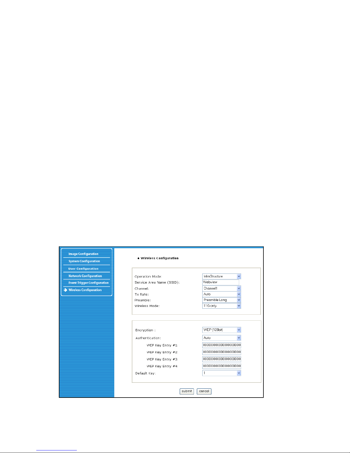
6.7 Wireless Configuration (for wireless cameras only. Model: MNC-WXXX)
This screen is used to configure wireless settings to match your access point for a wireless network
connection.
Page 46
46
6.7.1 Wireless Setup
1. Select the operation mode to determine the type of wireless communication for the Pro Series
Wireless Network Camera: Infrastructure or Ad hoc. The default setting is Infrastructure.
2. Set the service area name (SSID) in accordance with the access point settings to which the
camera should connect.
3. The channel is set to a default. In the infrastructure mode, the camera will automatically find
the access point. The channel only needs to be set in Ad-hoc mode.
4. The default setting for the "Tx rate" is Auto; however, it can be set up to 54 Mbps in 802.11g
mode and up to 11 Mbps in 802.11b mode.
5. The preamble mode should be set to Auto, but in some cases you may want to set it to either
long or short, depending on your setup.
6. The camera supports three different wireless modes:-11b/g Mixed (camera connects to any
11 or 54 Mbps wireless access point) -11b only (camera connects only to 11 Mbps wireless
access points)
-11g only (camera connects only to 54 Mbps wireless access points)
6.7.2 Wireless Security Settings
WEP
Wireless network communications are easily intercepted. WEP (wired equivalent privacy) is
anencryption method specified by the IEEE 802.11b standard to make any interceptedcommunications
extremely difficult to interpret by unauthorized parties.The WEP key needs to be entered in HEX code.
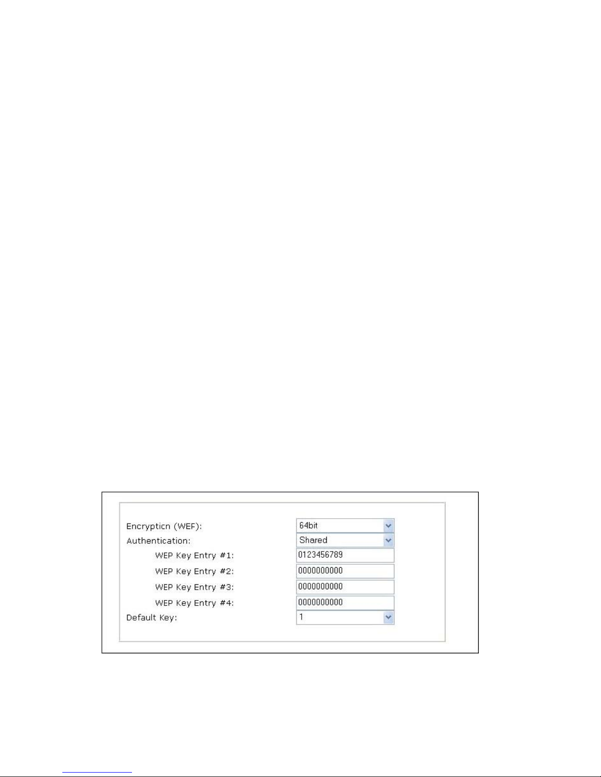
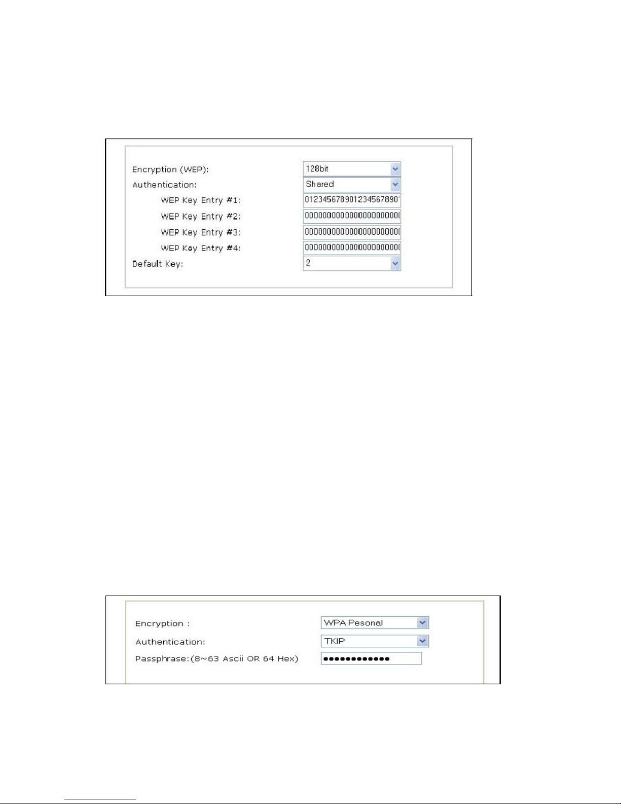
To set up 64-bit WEP, input 10 HEX characters,for example 0123456789. To set up 128-bit WEP input
26 HEX characters, for example01234567890123456789012345.
Authentication: WEP uses two types of authentication methods to authenticate the connection
request. One is Open key authentication, in which all clients are allowed to authenticate; the second is
Shared key authentication, which allows the AP (access point) to send the client a challenge text,
which the client encrypts and returns to the AP. If the AP successfully decrypts the challenge text, the
client is authenticated. Set the authentication type as per the access point authentication type. The
wireless camera’s Auto mode automatically switches between open and shared modes.
Example 1: If your access point uses 64-bit encryption, the default key is 1, authentication is shared
and the key value is 0123456789. Your wireless camera WEP setting will be:
Page 47
47
Example 2: If your AP uses 128-bit encryption, the default key 2, authentication is shared and the key
value is 01234567890123456789012345. Your wireless camera WEP setting will be:
NOTE: All four WEP keys need to be set up the exactly same way they are defined in your wireless
access point. Make sure the encryption code is the same as that of the access point to which your
camera will be connected under Infrastructure mode. Your PC’s encryption code also needs to be set
up to match the camera’s encryption code under either Infrastructure or Ad hoc mode. The default
setting for the encryption key is Disable; therefore, to secure the wireless transmission, be sure to
enable the encryption key by entering the relevant data.
NOTE:
Carefully enter encryption codes, as any error will cause the communication link to fail.
WPA & WPA2 (personal)
Wi-Fi Protected Access (WPA and WPA2) is a more effective way to secure wireless (Wi-Fi) computer
networks. It was created in response to several serious weaknesses which researchers had found in
the previous system, Wired Equivalent Privacy (WEP). WPA implements the majority of the IEEE
802.11i standard, and was intended as an intermediate measure to take the place of WEP while
802.11i was prepared. WPA is designed to work with all wireless network interface cards, but not
necessarily with first generation wireless access points. WPA2 implements the full standard, but will
not work with some older network cards. WPA and WPA2 provide good security, with two significant
issues:
Either WPA or WPA2 must be enabled and chosen in preference to WEP. WEP is usually presented
as the first security choice in most installation instructions. The most common choice for homes and
small offices is the "Personal" mode, for which a pass-phrase is required. For full security, the
pass-phrase must be longer than the typical 8 to 10 characters in ASCII or 64 hex characters.
Pre-shared key mode (PSK, also known as personal mode) is designed for home and small office
networks that cannot afford the cost and complexity of an 802.1X authentication server. Each user
must enter a pass-phrase to access the network. The pass-phrase may be from 8 to 63 printable
ASCII characters or 64 hexadecimal digits (256 bits).
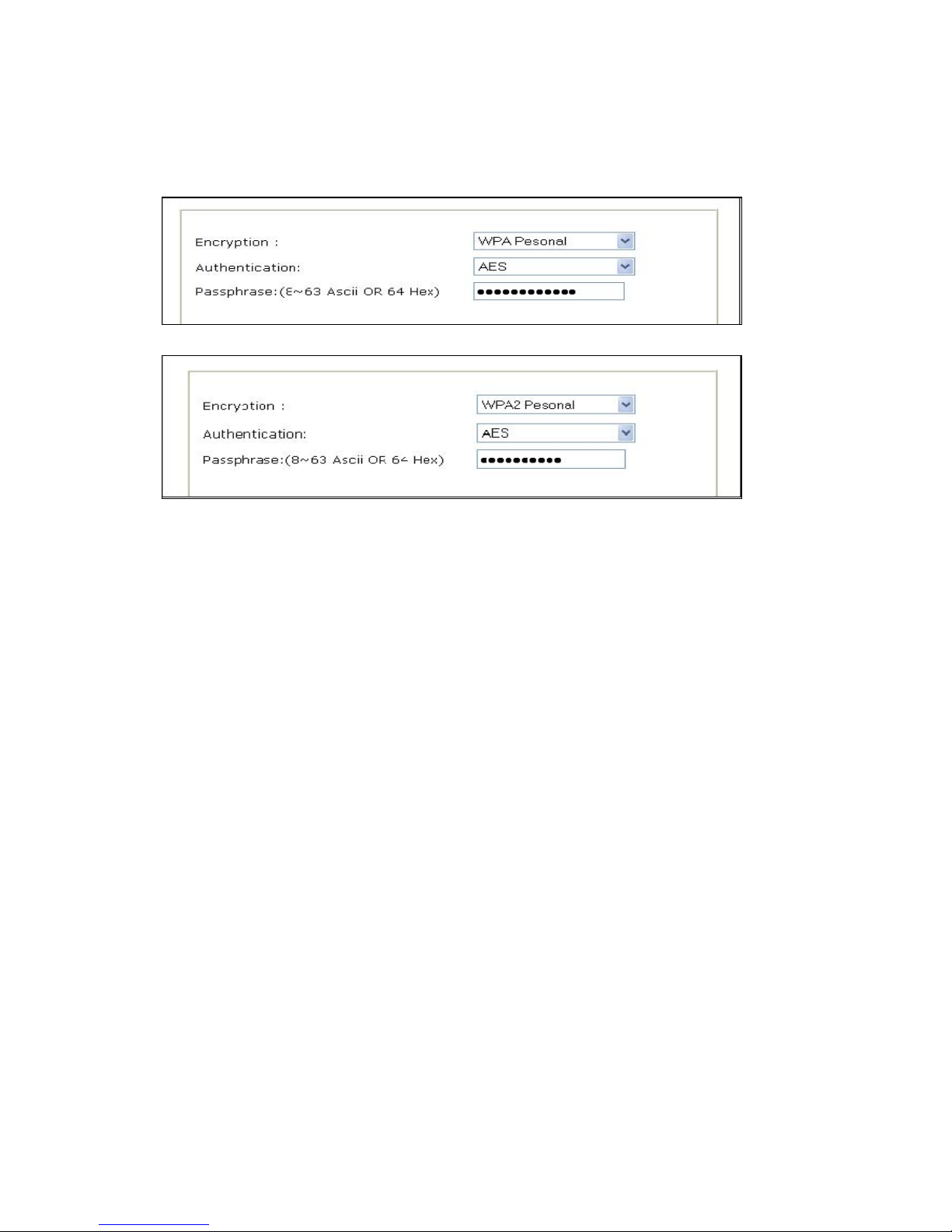
Example 1 : WPA Personal encryption with TKIP authentication enabled.
Page 48
48
Example 2: WPA Personal encryption with AES authentication enabled.
Example 3: WPA2 Personal encryption with AES authentication enabled.
IMPORTANT
Infrastructure Mode
This is an 802.11 networking framework in which devices communicate with each other by first going
through an access point (AP). In Infrastructure mode, wireless devices can communicate with each
other or can communicate with a wired network. When one AP is connected to a wired network and a
set of wireless stations, it is referred to as a basic service set (BSS). An extended service set (ESS) is
a set of two or more BSSs that form a single sub network. Most corporate wireless LANs operate in
Infrastructure mode because they require access to the wired LAN in order to use services such as file
servers or printers.
Ad hoc Mode
This is an 802.11 networking framework in which devices or stations communicate directly with each
other, without the use of an AP. Ad hoc mode is also referred to as Peer-to-Peer mode, or an
independent basic service set (IBSS). Ad hoc mode is useful for establishing a network in which a
wireless infrastructure does not exist or in which services are not required.
SSID (service set identifier)
This is a 32-character unique identifier attached to the header of packets sent over a WLAN that acts
as a password when a mobile device tries to connect to the BSS. The SSID differentiates one WLAN
from another, so all access points and all devices attempting to connect to a specific WLAN must use
the same SSID. A device will not be permitted to join the BSS unless it can provide the unique SSID.
An SSID is also referred to as a network name because, essentially, it is a name that identifies a
wireless network. To connect a wireless client such as a Wireless Pro Series Network Camera to a
specific AP, the user of the camera should specify the SSID name in the camera’s wireless IP setting.
Page 49
49
7. PoE (Power over Ethernet) Support
Power over Ethernet, or PoE, technology describes a system to transmit electrical power, along with
data, to remote devices over standard twisted-pair cable in an Ethernet network. This technology is
useful for powering IP telephones, wireless LAN access points, network cameras, remote network
switches, embedded computers, and other appliances where it would be inconvenient, expensive
(mains wiring must often be done by qualified and/or licensed
The standard IEEE 802.3af describes two types of devices: Power Sourcing Equipment (PSE)and
Powered Devices (PD). Power sourcing equipment provides power to the powered devices. The
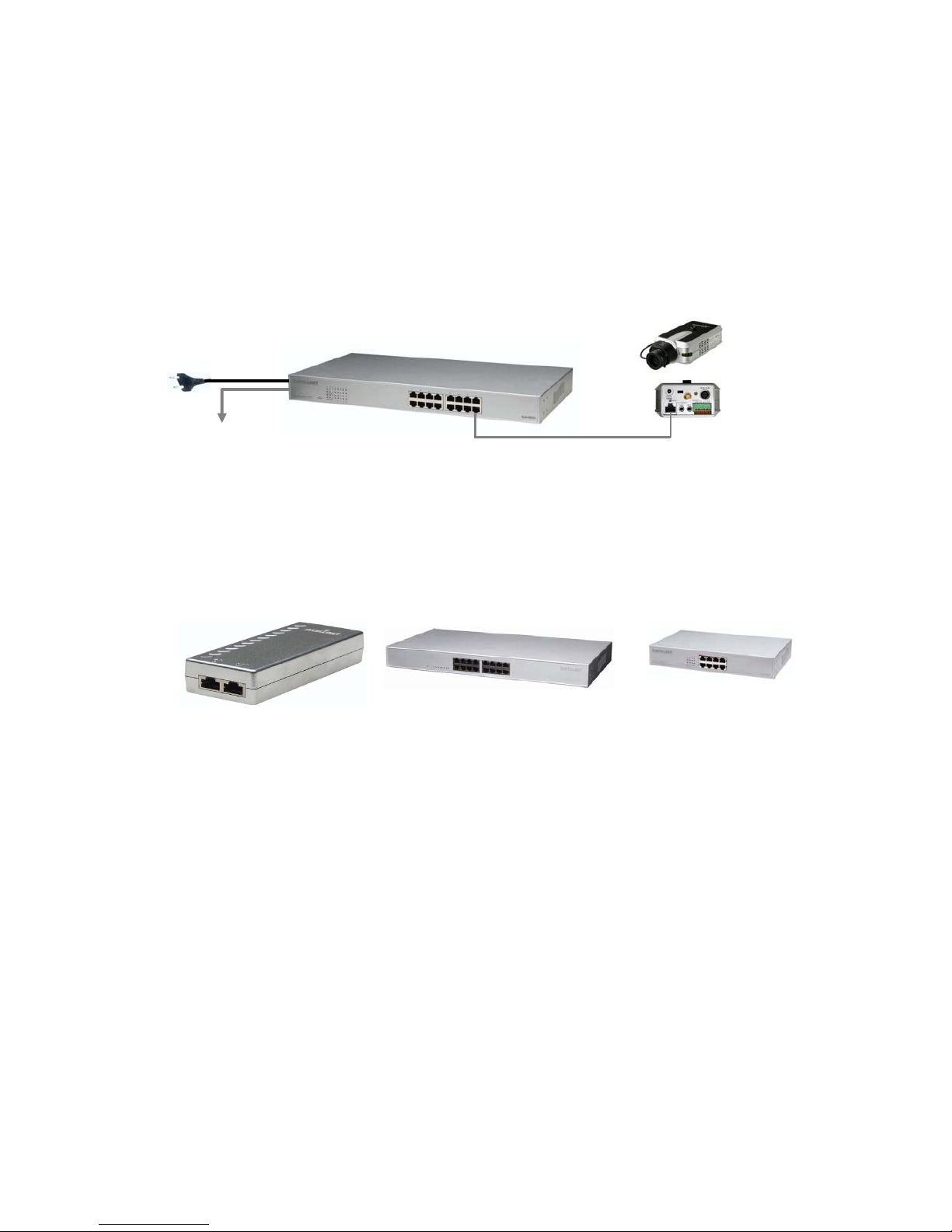
network camera represents the powered device, whereas a PoE Injector is a PSE device. The Pro
Series Network Camera models are IEEE 802.3af standard PoE compliant. They can be used with any
IEEE 802.3af-compliant PoE injector, PoE switch, PoE mid-span and PoE end-span.
Various types of PoE equipments
PoE Switch / Mid-Span / End-Span
AC Power
Ethernet
Direct connection with standard LAN cable
Power over Ethernet (PoE) Injector PoE Mid-span PoE Office Switch
Page 50
50
8. ETSP Client
ETSP stands for "Event Triggered Saving Program." This utility allows you to automatically record
video on the HDD of your computer whenever the camera detects a motion. The latest version of
ETSP Client is available on networkipcamera.com as a free download.
Getting Started
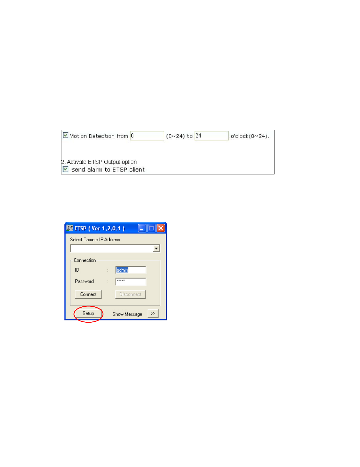
To use ETSP Client, you first need to activate the ETSP option in the Event Trigger
Configuration of the camera. See section 6.5 for additional information.
1. Activate Motion Detection
Once this is activated, the camera will send a "signal" to the network whenever motion is detected.
ETSP Client is designed to monitor the camera for this signal. When ETSP detects this signal, it starts
recording immediately. The following steps only need to be performed the first time you run ETSP
Client.
Setting up the camera in ETSP Client
Double-click the ETSP Client program to start it. The following screen appears:
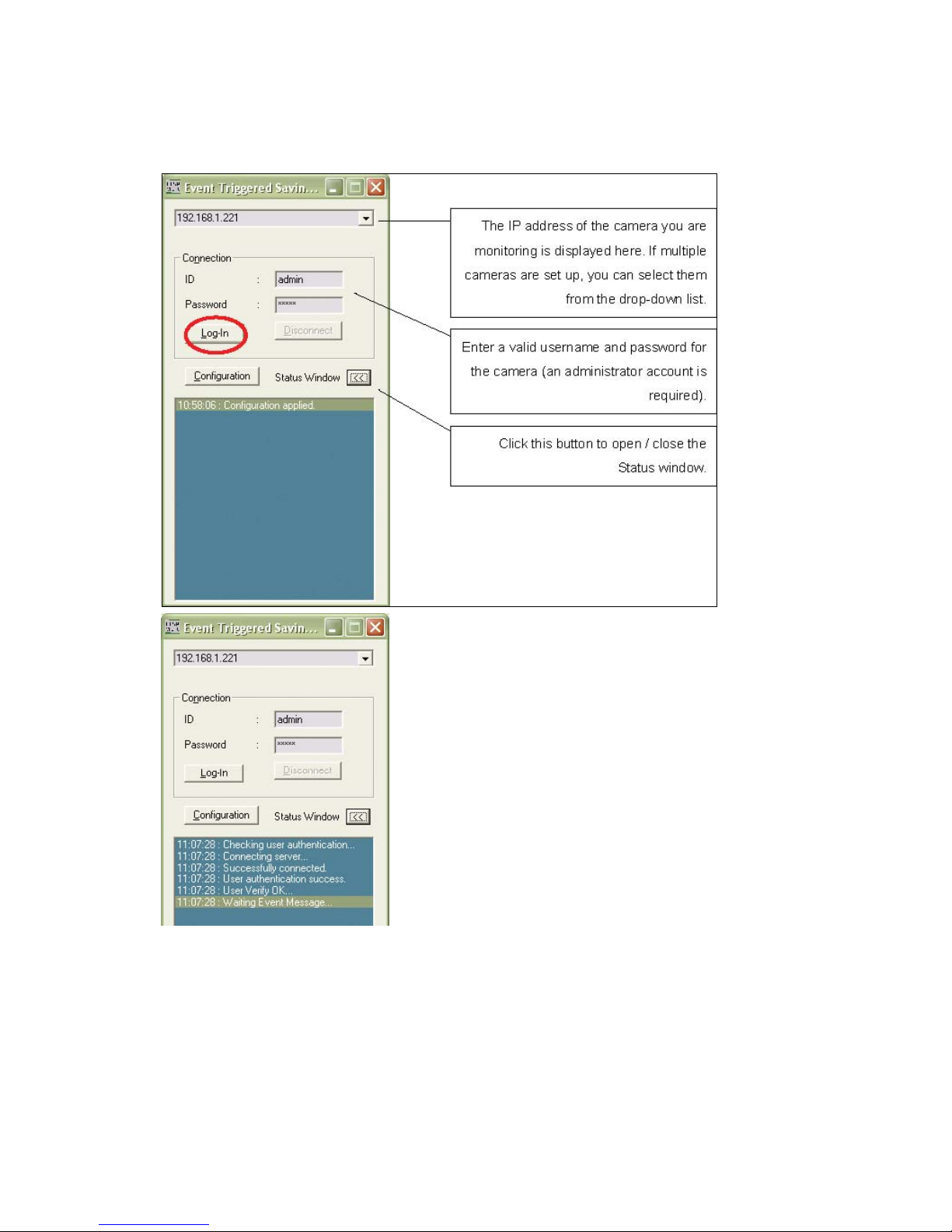
Select camera IP address and then click on "Setup" to open the camera configuration screen.
Page 51
51
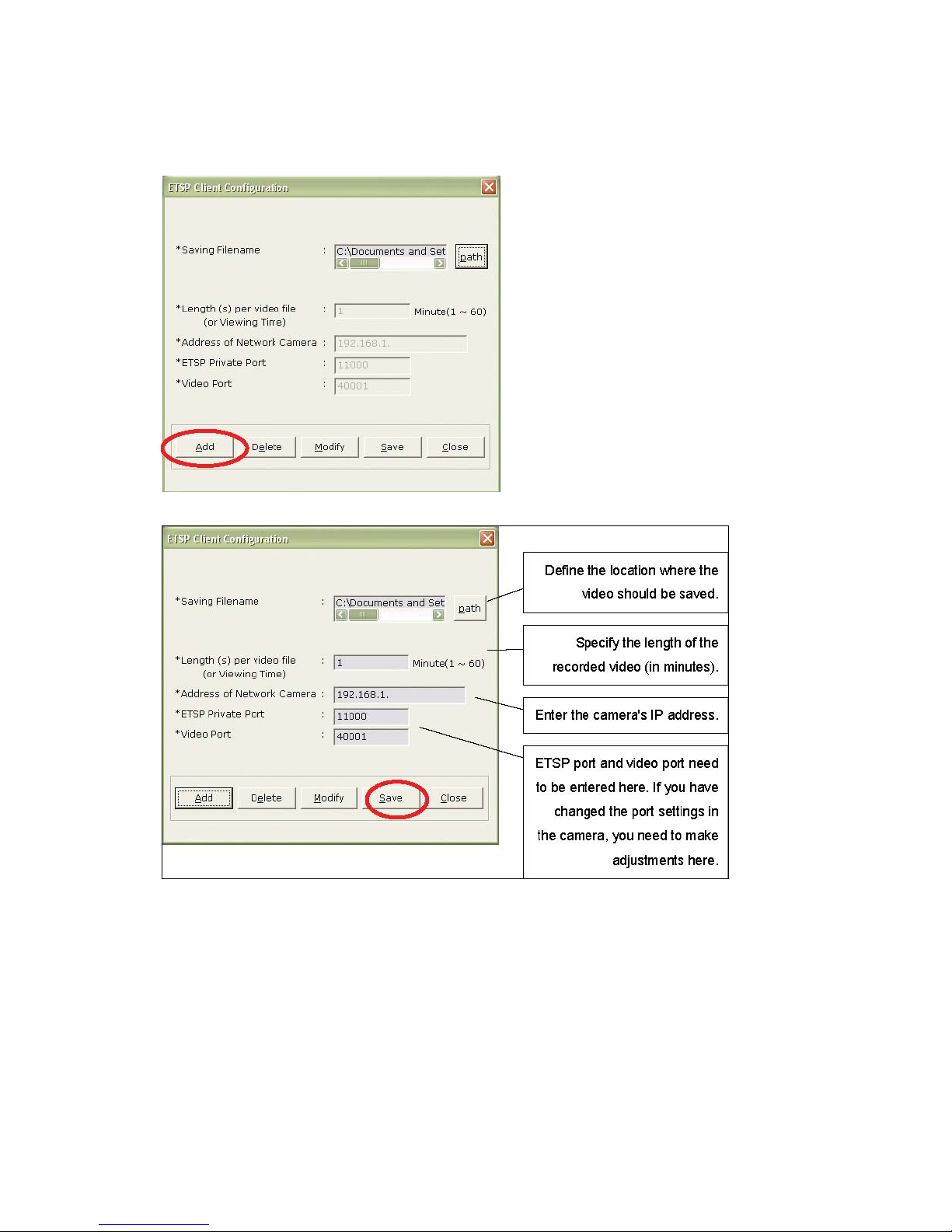
Click "Add".
Click "Save" to save the settings and open the main screen of ETSP Client. Click on "Login" to start the
monitoring and recording process.
Page 52
52
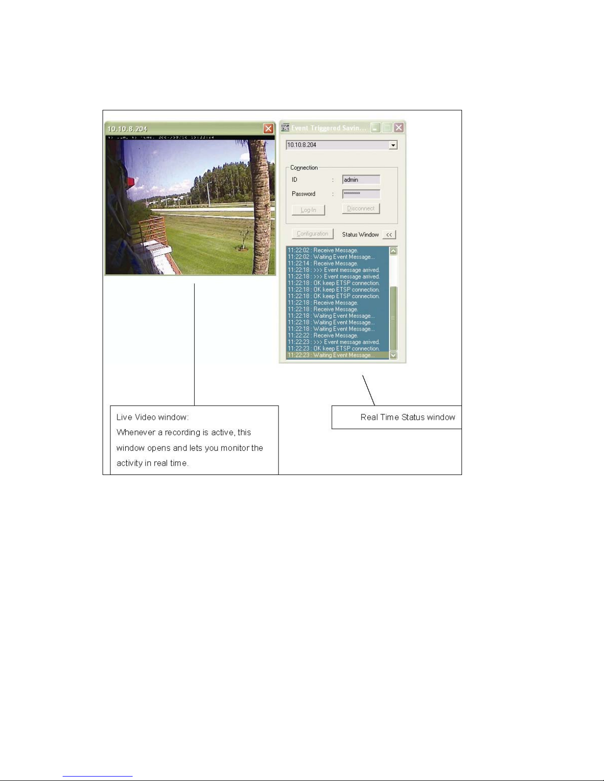
ETSP Client is now connected to the camera.
Page 53
53
Page 54
54
9. RTSP Video Playback
RTSP stands for "Real Time Streaming Protocol ." RTSP enabled video streaming clients, such as
MPlayer, can access the video data stream of the camera directly and you can watch the live video
without connecting to the camera with your Web browser first. MPlayer is freeware.
RTSP Playback in MPlayer for Windows
1. Activate MPEG4 streaming in the system configuration of the camera
2. Alternatively, you can activate Dual mode(MPEG4&JPEG) with MPEG4 output streaming type
in the system configuration of the camera
Page 55
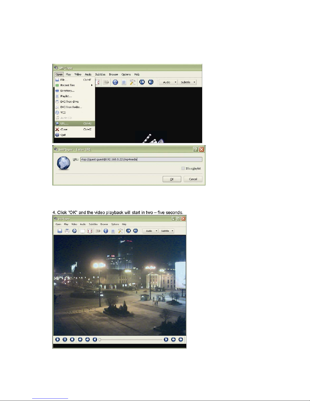
55
3. In MPlayer, click on OPEN -> URL 3. Enter the correct address to your camera
URL: rtsp://guest:guest@192.168.0.221/mp4media
guest:guest = valid user name and password
192.168.0.221 = IP address or web address of your camera mp4media = fixed part of the URL
Page 56
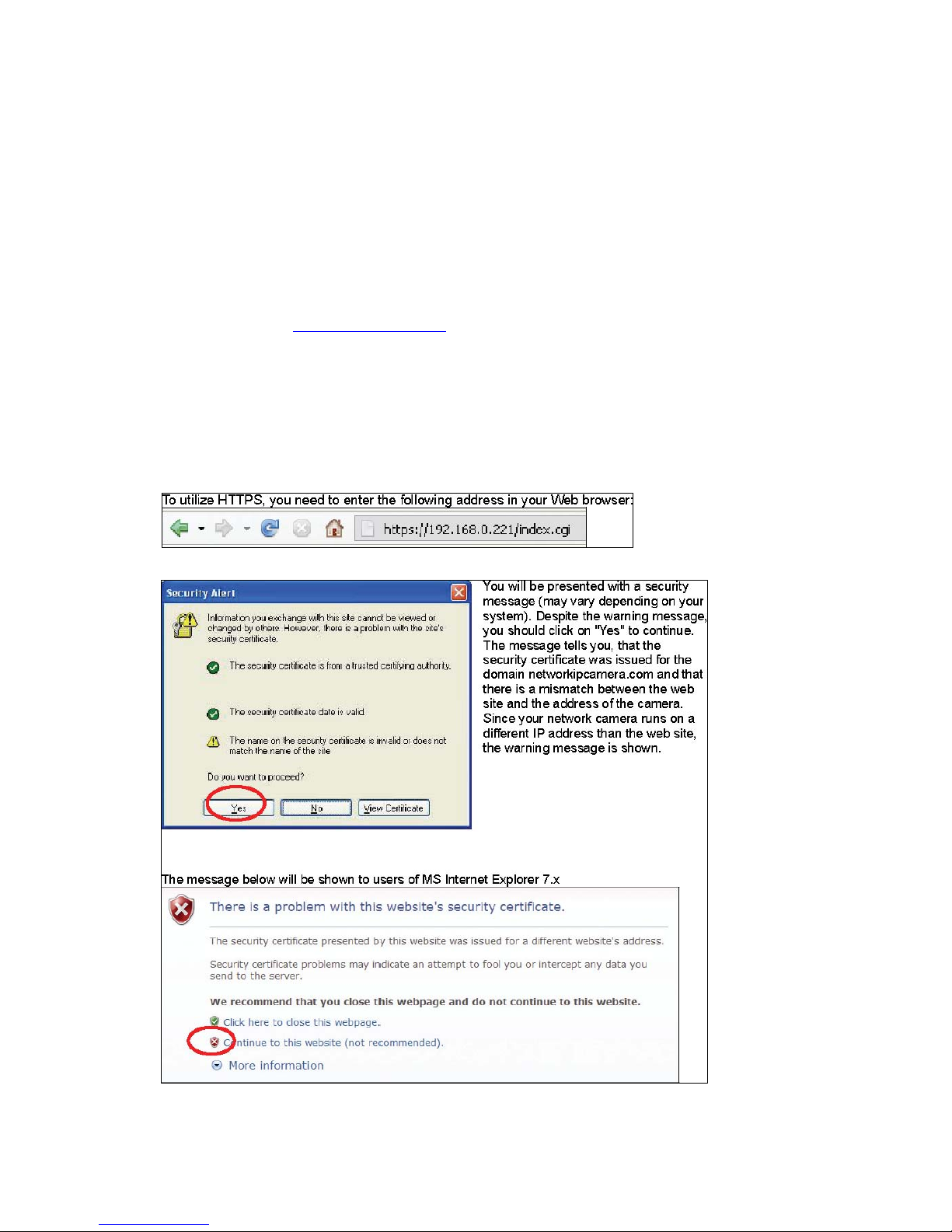
56
Note:
1. RTSP support is limited to the Pro Series Dual Mode IP Camera models.
MNC-L10M20/MNC-W10M20 and MNS-102 do not support RTSP.
2. RTSP support may not work with all RTSP enabled clients; e.g., RTSP is incompatible to
Microsoft's Windows Media Player.
3. RTSP support requires the camera to have an updated firmware installed. If the network
settings page of your camera does not show a port for RTSP, you need to update the
firmware at www.networkipcam.com
.
4. As new versions of RTSP enabled clients are released, compatibility to the network camera
can not always be guaranteed.
10. SSL Encryption / Access via HTTPS
The MPEG4 cameras are equipped with SSL encryption, a safe way of accessing your camera. SSL
encryption ensures, that the data traffic between your camera and the computer is encrypted.
Access to the camera via HTTPS:
Note: Use "https" instead of "http".
Page 57
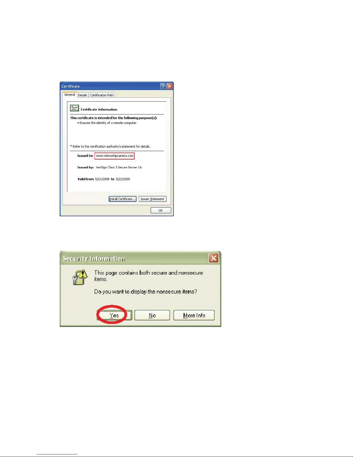
57
Click "Continue to this website (not recommended)" to proceed.
Click on "View Certificate" to view the details. The image on the left shows a screenshot of MS Internet
Explorer 6.x.
The certificate must be issued to www.networkipcamera.com.
You may be seeing the warning below:
This message is shown, whenever a web site with secure and non-secure elements is shown.
Non-secure elements can be images which are not crucial for the security. The question should be
answered with "Yes".
Page 58
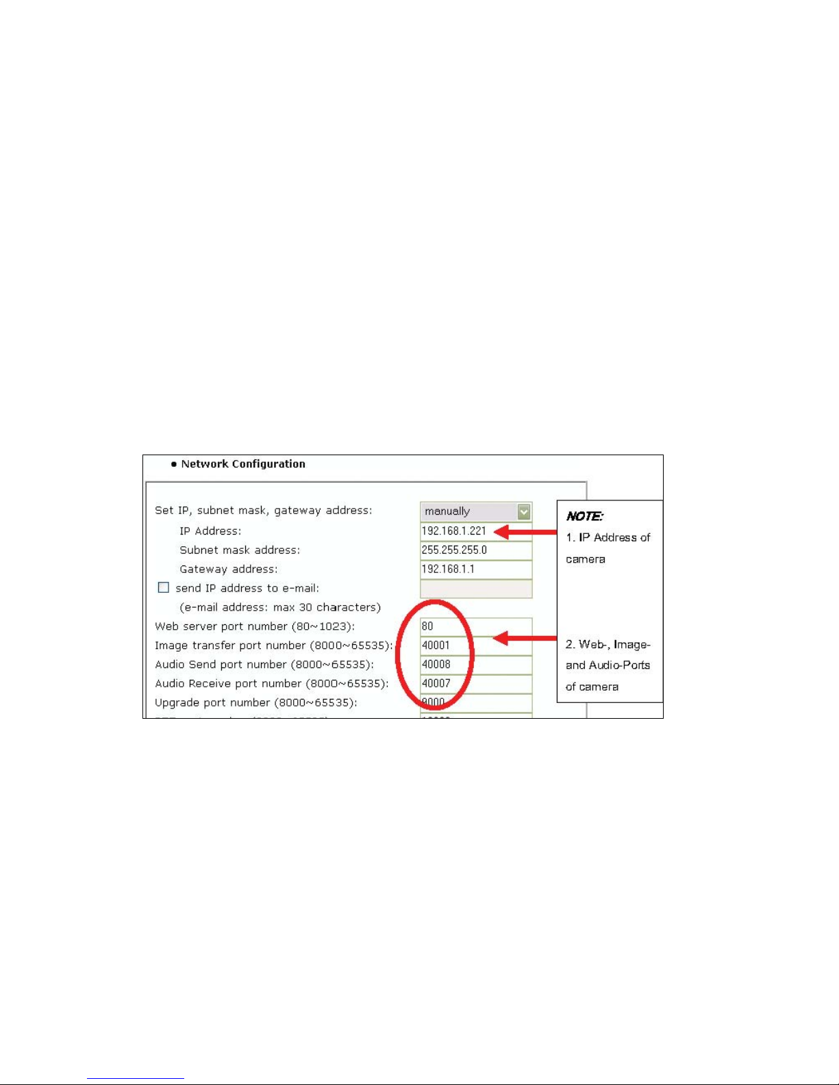
58
11. Remote Access to a Camera & Router Setup
To gain access to a camera in your local network over the Internet, certain ports need to be
opened and forwarded in your router. The camera uses the following ports by default:
9 - Web Server port = 80
9 - Image Transfer port = 40001 -Audio Send port = 40008
9 -Audio Receive port = 40008
9 - Upgrade port = 9000
9 - PTZ port = 10000
9 - ETSP port = 11000
To view the live image over the Internet, the Web server port and image transfer port need to be
opened and forwarded in the router. To receive and send sound, the audio send and receive ports
must also be added to the router configuration.
Before you can add the information in the router, find out which local IP address your camera has
and which ports it uses by connecting to the camera's Web administrator menu (Network
Configuration screen).
MPEG4 Network Camera default values
On the following pages are setup examples for several routers. The procedure for other routers from
other brands is very similar, but some details may be different.
Setup Example 1: MIMO Wireless Turbo G Router and Wireless N Router:
Click on NAT -> Virtual Server. Check (x) Enable Virtual Server. Enter the camera IP address, along
with the Web server (private and public port should be identical), select type = TCP and enter a
description in the comment field. Click on ADD. Repeat the steps for the other ports.
The end result should look like this:
Click "Apply" to save the settings.
Page 59
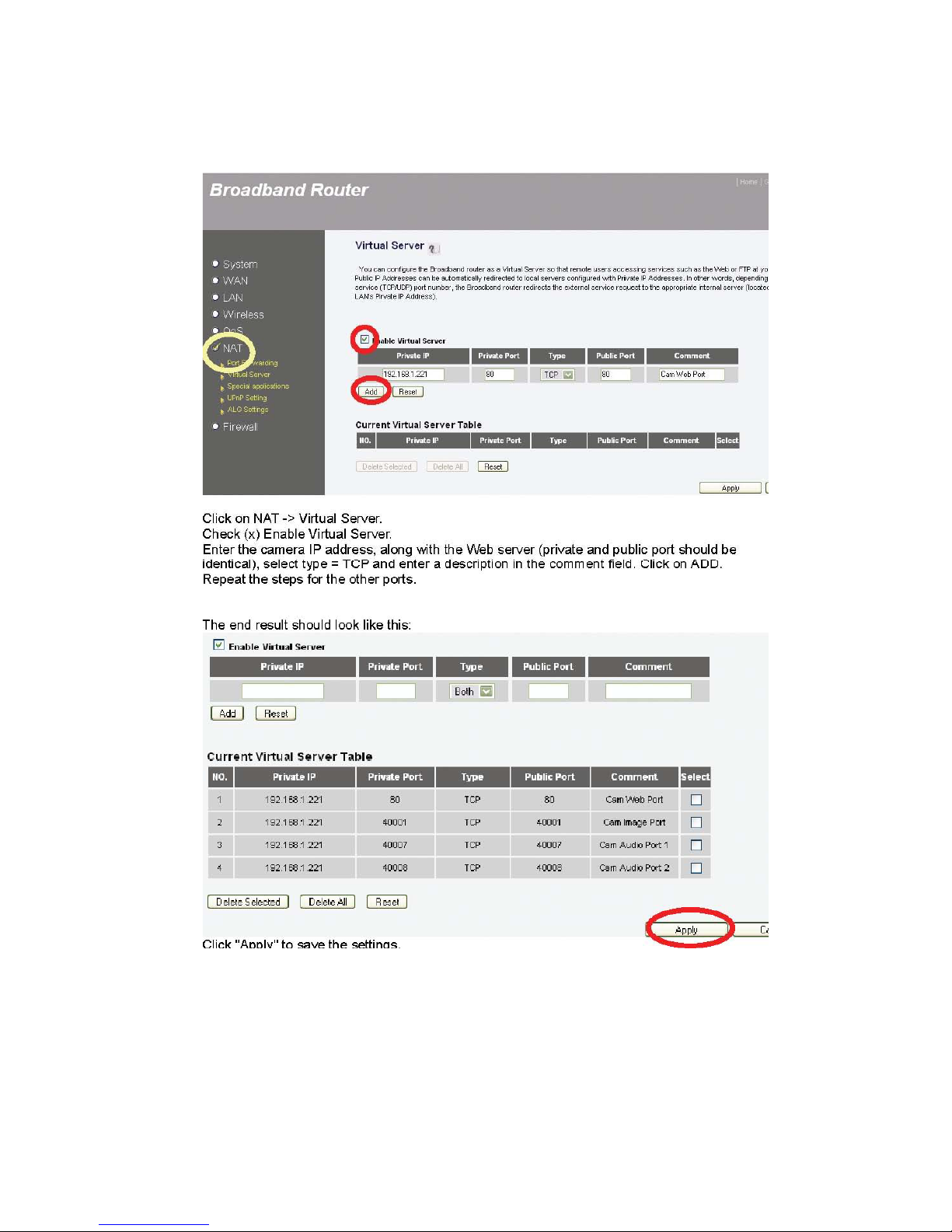
59
Page 60
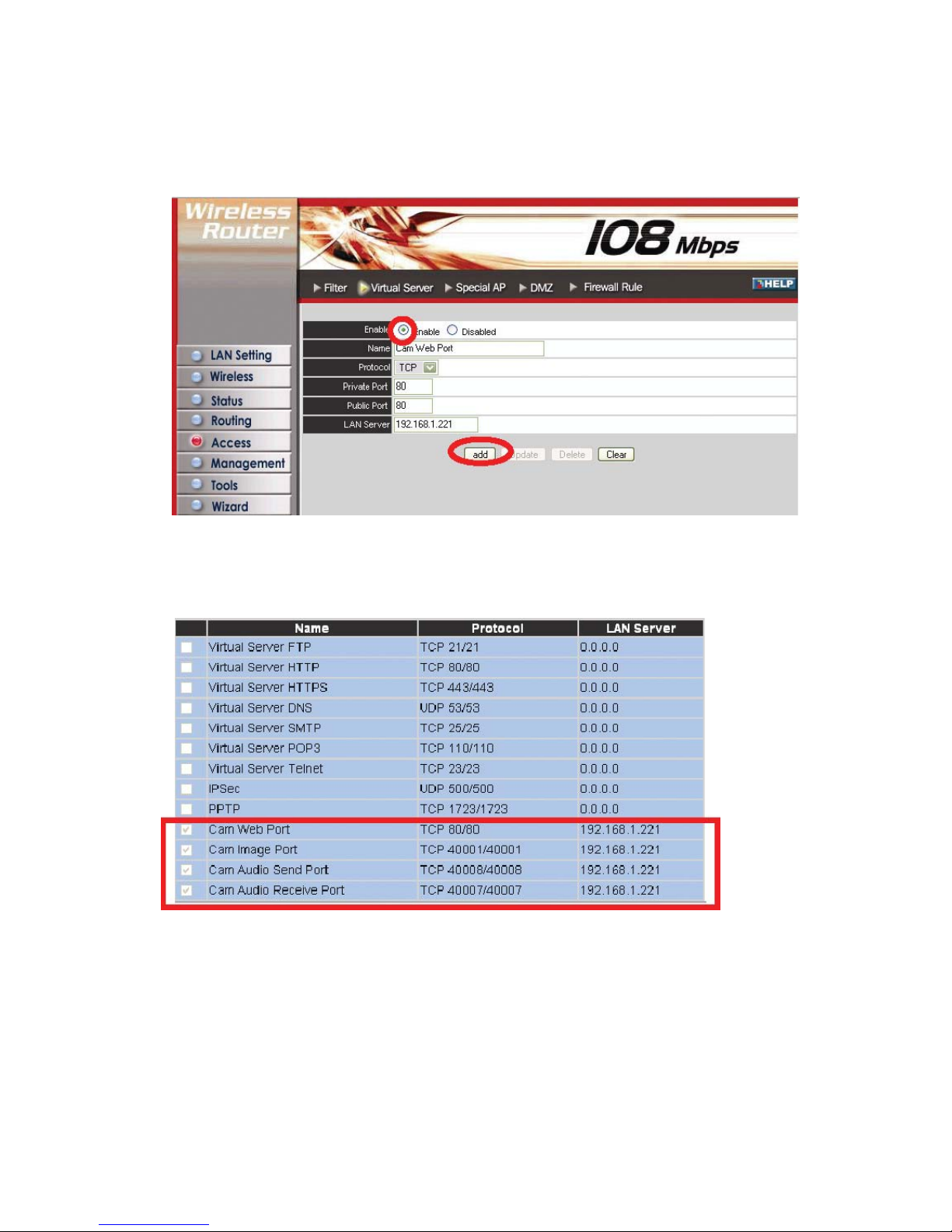
60
Setup Example 2: Wireless Super G Router
Click on Access -> Virtual Server. Check (x) Enable Virtual Server. Enter a descriptive name and the
public and private ports, then select TCP as the protocol and enter the IP address of the camera as the
LAN Server. Click on "add."
The end result should look like this:
Page 61
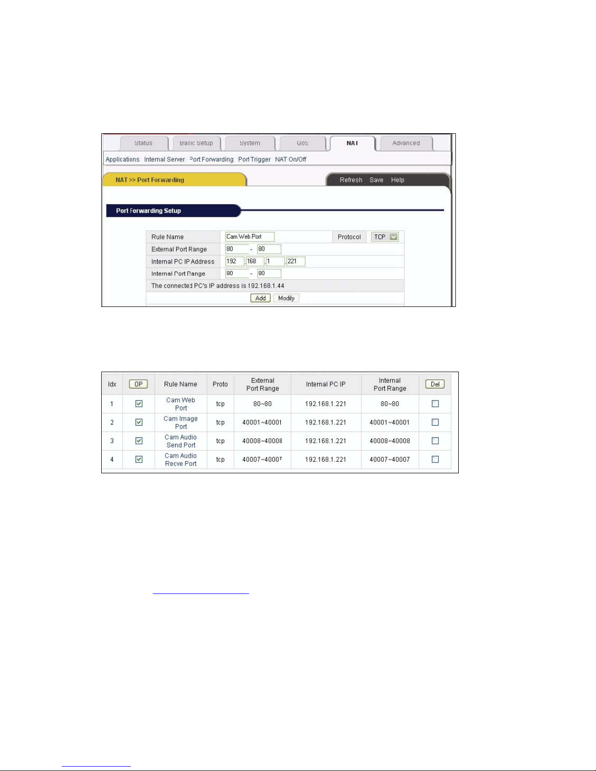
61
Setup Example 3: Wireless G Broadband Router, 4 Port Broadband VPN Router, 8 Port
Broadband VPN Router and Dual WAN Router.
Click on NAT -> Port Forwarding. Enter a rule name, external port range, camera IP address and
internal port range. The above example shows port 80. Click "Add" to save the rule. Repeat the steps
for the other ports.
The end result should look like this:
Even though the camera only requires four single ports to be forwarded, and not a range of ports, you
still need to enter the single ports as port ranges into this router model.
12. Developer Information
This section of the user manual contains useful information for software developers and Web
programmers.
12.1 Software Development Kit (SDK)
Software developers can download an SDK for WEBVIEW Pro-Series cameras and network video
servers from www.networkipcam.com
. The SDK consists of different documents, sample programs
and sample code snippets for various applications.
The SDK contains:
HTTP API
WEBVIEW Network Cameras support HTTP CGI calls to perform certain functions, or to remotely
program the camera. As a developer you have access to virtually every parameter the camera has
to offer: You can query the alert state of the camera and trigger the digital I/O port, and change
Page 62
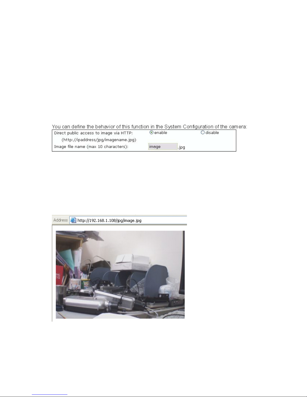
62
image settings and network parameters remotely.
Web Integration
Documentation to integrate the live video of the camera in an HTML page that can be viewed with
any standard Web browser.
MS Visual Studio (C++, Visual Basic)
Documentation helpful for Windows program developers to assist in writing custom applications for the
WEBVIEW network camera.
12.2 Direct Access to internal JPEG
To utilize the camera in third-party video surveillance programs, you can activate the direct image
access. It allows accessing the internal JPEG image of the camera that other programs can download.
Direct public access to image via HTTP:
enable: Any user can access the image. No username or password is required to see the image.
disable: A username and password must be provided in order to see the image.
Image file name (max. 10 characters):
The default name is "image," but you can change it for security reasons.
You can access the image using the URL below:
http://camera_ip/jpg/image.jpg
Enter the URL in your Web browser. After you enter the username and password, you can see the
live image. Refresh the view to see the most current image.
12.3 Motion-JPEG Access
The MPEG4 cameras support a dual-mode streaming capability. This means that the camera can
output MPEG4 and Motion-JPEG video data simultaneously. Motion-JPEG is the preferred method
when using the camera with third-party video surveillance applications. It is widely supported, and is
Page 63
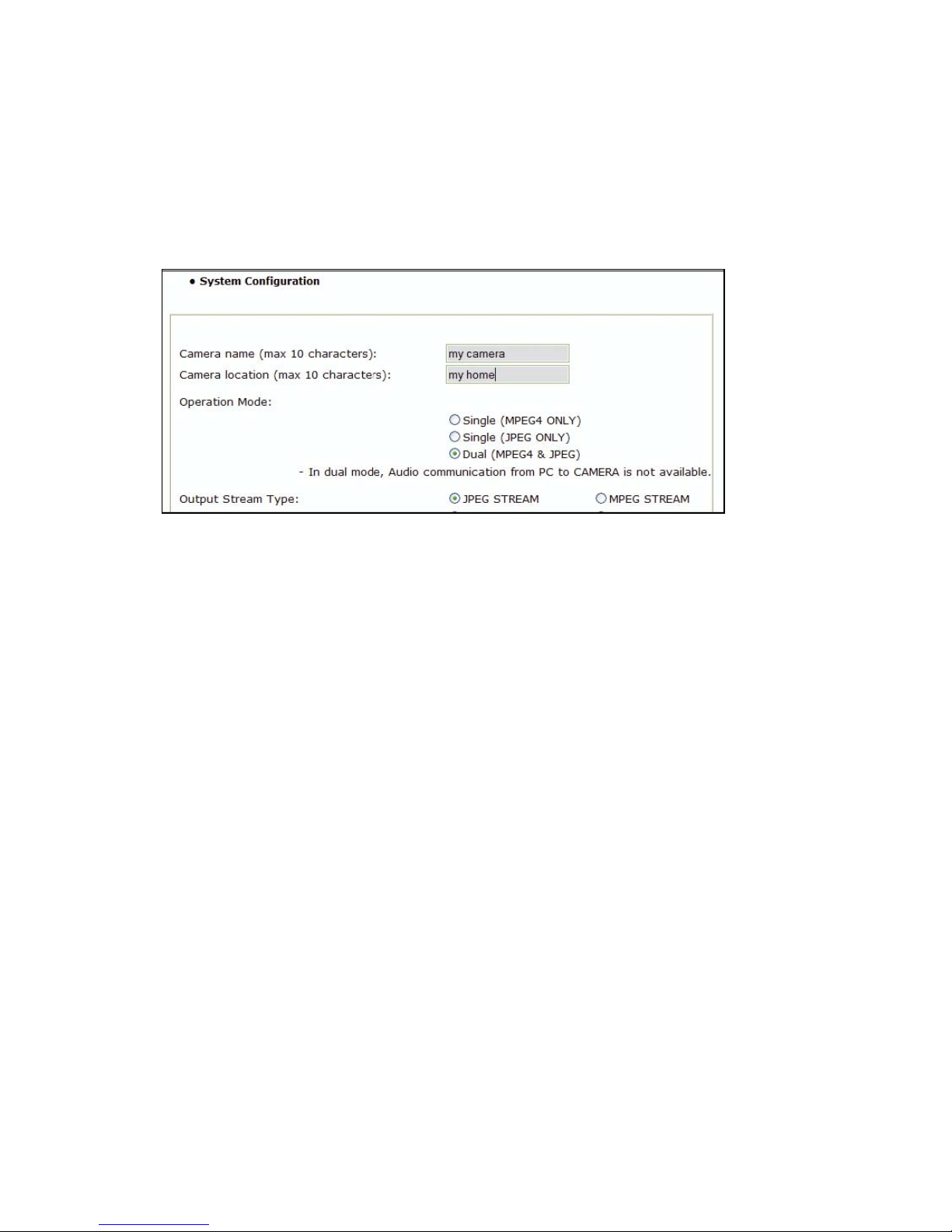
63
often the only image format accepted by courts, who consider MPEG4 compression too lossy.
Motion-JPEG video, on the other hand, cannot compress video data as effectively as MPEG4 does.
Thus, the resulting video stream requires a higher network bandwidth.
To utilize the Motion-JPEG stream, first enable dual mode streaming in the camera's system
configuration.
The Operation Mode parameter needs to be set to "Dual (MPEG4 & JPG)." The following
URL returns the Motion-JPEG stream:
http://camera_address/image.cgi?id=guest&passwd=guest&mode=http
Appendix A: Frequently Asked Questions (FAQ)
1. What is the default IP address of the network camera?
The default IP address is 192.168.1.221
2. I use a MacOS or Linux system and cannot use IP Installer to set up my camera. How can I
install the camera without that tool?
1. You will need to change the IP address of your MacOS or Linux PC so that it is in the range of
the camera's default IP address: 192.168.1.221 (network mask 255.255.255.0). For example,
you can set the IP address of your computer as 192.168.1.100 (subnet mask 255.255.255.0).
For information on how to manually set the IP address of your system, refer to the
documentation of the operating system you are using.
2. Then you can open the camera homepage in your Web browser and change the camera's IP
information on the Network Configuration screen of the administrator menu (see section 6.3).
3. After changing the Camera's Web Server Port from 80 to a different value, access to the
camera is no longer possible.
Whenever you change the Web server port from the standard 80 to a different value, you need to
append the port to the camera's IP address. The syntax is always http://cameraip:portnumber.
Example: When you change the Web server port to 81, the correct address would be:
http://192.168.1.221:81.
4. IP Installer does not find the camera. Why?
The camera is installed behind a PoE (Power over Ethernet) device. Remove the PoE temporarily or
set up the camera without IP Installer.
A desktop firewall application such as Norton Internet Security (NIS) is installed. Uninstall NIS or set up
the camera without IP Installer.
Page 64
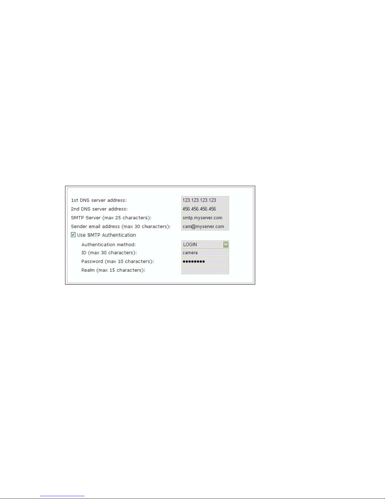
64
Windows XP SP2 is installed and the integrated firewall is active. Deactivate the Windows firewall
temporarily or set up the camera without IP Installer.
The network connection to the camera is not working. Verify that the camera has an active network
link.
The camera needs a reset. See Appendix H: Reinstating the factory default settings.
5. Can I use the camera's integrated motion detection function to secure sensitive areas and
goods of a high value?
Using the Network IP Camera's integrated motion detection function for security functions is not
recommended, as the function does not work as reliably as professional security sensors.
We recommend using professional security monitoring software in combination with the Network IP
Camera. You may also connect external security sensors to the camera's digital input port for
increased security.
6. How do I activate the E-mail Function?
a) Camera Network Configuration
DNS Server Address
A DNS server is required if you enter the SMTP server using the domain name. If you enter the IP
address of the SMTP server you do not need to specify DNS server information, but if you enter the
domain name of your mail server (e.g., mail.myserver.com or smtp.myserver.com) you need to type in
at least one DNS server.
SMTP Server (max. 25 characters)
Type in the address (IP address or domain name) of the outgoing mail server. This is typically the
same mail server you have set up in your mail client settings (e.g., the MS Outlook profile).
Sender e-mail address (max. 30 characters)
This should not be left blank as many SMTP servers refuse to deliver e-mail if the sender address
is missing. The sender address can be any e-mail address. It does not need to be a real, existing,
e-mail address. You can type in [email protected] or [email protected].
Use SMTP Authentication
Most SMTP servers are password protected to prevent illegal access (anti-spam). If your SMTP server
requires authentication, enter the username and password required for this server. Those are the same
values you normally use for the Email Client (Outlook, Thunderbird) on your PC.
Authentication method
The authentication method should be set to LOGIN in most cases. Unless your server specifically
Page 65
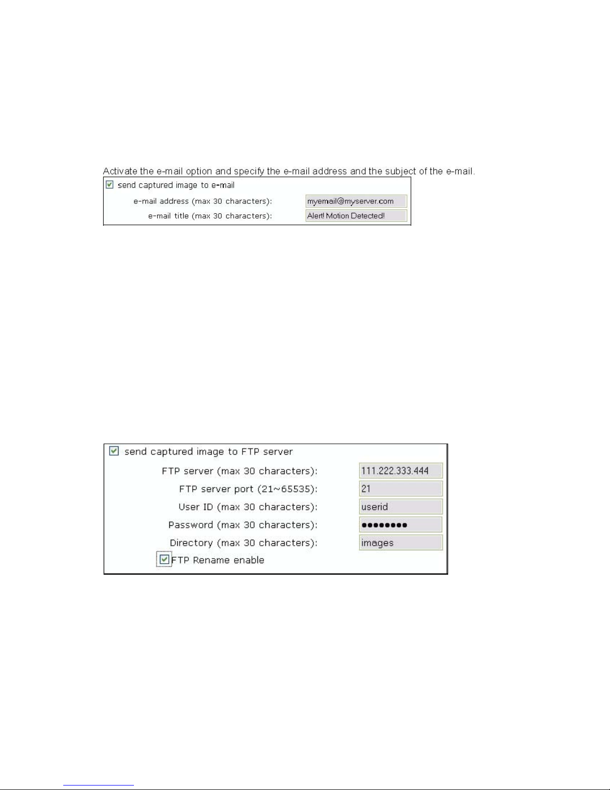
65
requires different settings, LOGIN is the preferred choice. Other options are PLAIN and
DIGEST-MD5.
If your server is an Open Relay, you do not need to activate SMTP authentication.
b) Camera Event Trigger Configuration
7. The camera does not send any e-mails. Why?
1. 1. The problem occurs because the camera cannot contact the E-mail server
2. Check: -Is the e-mail (SMTP) server address correct? (Network Configuration) -Did you
specify the correct gateway IP address? (Network Configuration)? -Did you specify correct
DNS servers? (Network Configuration) -Did you enter the correct e-mail address? (Event
Trigger Configuration) -Did you specify the e-mail title? (Event Trigger Configuration)
3. The e-mail server denies the delivery request from the camera
Check:
9 Is a valid sender address specified? (Network Configuration)
9 Did you activate SMTP authentication? (Network Configuration)
9 Did you enter the correct Username and Password for SMTP authentication? (Network
Configuration)? Also be sure to have the latest firmware installed in case you experience
difficulties. Possible compatibility problems are likely to be resolved in newer firmware
versions.
8. How do I activate the FTP upload function?
( ) send captured image to FTP server
Activate this option.
FTP Server (max 30 characters)
Type in the IP address or domain name of the FTP server (if you enter the domain name, you must
have proper DNS servers set up in the network configuration).
FTP Server Port
By default, the FTP service runs on port 21. If your server runs on a different port, you can enter the
correct port here.
Page 66

66
User ID (max 30 characters)
Enter a valid FTP server user name.
Password (max 30 characters)
Enter a valid FTP server password.
Directory (max 30 characters)
Enter the directory on the server where the images are to be uploaded.
FTP Rename enable
Activate this option if you want the server to rename the image after the upload is completed.
9. What does the FTP Rename option in the Ev ent Trigger Configuration do?
The FTP Rename option should be activated whenever the camera uploads the same image (same
image name) to the FTP server. Typically this is an application where the camera uploads still images
to your Web site every xx seconds and you display the image on your Web site.
Without the Rename option enabled, the following will happen: The FTP
upload process consists of different steps.
1. Login
2. Delete existing file
3. Upload new file
4. Logout The entire process can easily take several seconds, depending on the camera's
Internet connection speed as well as the image size.
The important thing here is that the existing image first is being deleted, then the new image is being
uploaded. If a user accesses your Web site at the very moment the image is deleted or is being
uploaded, the image on the Web site will either not show up at all or will only show partially.
With the Rename Option enabled, this does not happen. The image will always show up correctly.
Here is why: Instead of deleting the existing image first, the camera uploads the new image using a
different file name. Example: Image name: camera.jpg Image name of file the camera uploads:
camera_tmp.jpg
This way, the current image will still show up for Web users even if the camera already uploads a new
image. Once the upload of the new image is completed, the camera instructs the FTP server to delete
the existing image and rename the new image to the old image. Since this is done on the server itself,
this takes only a fraction of a second. Thus, the image on your Web page will always show up
correctly.
In short:
You should activate the Rename option, if the Network IP Camera refreshes an existing image on the
FTP server which can be seen on a Web site.
You do not need to activate the Rename option, if the Network IP Camera uploads a series of
images with changing file names (e.g., with the date and time included in the file name).
10. Why won’t the ActiveX control automatically download?
Situations occasionally arise which prohibit this from happening. If Internet Explorer is an earlier
version than 4.0, or if the registry information of the system is corrupted, the automatic download and
installation may fail. If problems occur with automatic download, try a manual download. (See
Installation of ActiveX in 4.3.)
11. Even though I enter the right ID and password to log in, the error message "You must login
first" appears. What’s wrong?
Page 67
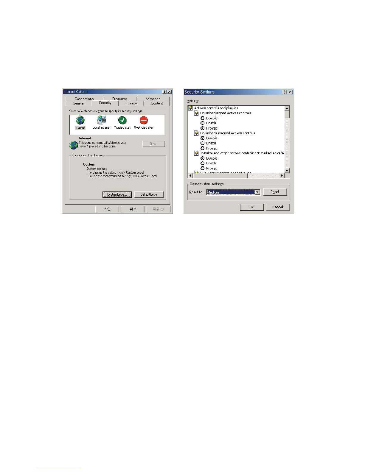
67
Open "Internet Options" in MS Internet Explorer and then click on the "Security" tab to view the setting.
(If set on "High," ActiveX would have a problem downloading.) You can manually install the ActiveX
control as described in section 4.3 or change the security settings to a lower level.
12. I want to connect to the camera using Java; however, on my new Windows system there's
no Java Virtual Machine installed. Where do I get it?
You may download the Java software directly from Sun's Java Web site. Java
Virtual Machine for Windows:
http://www.java.com/en/download/windows_manual.jsp
Appendix B: Accessing the camera via HyperTerminal
NOTE: This section is for advanced users only.
HyperTerminal is a basic program for Windows 9x/NT/2000XP/Vista. A PC can communicate with
external devices through the serial port by using this program. The steps you should take to set the
HyperTerminal are as follows with a Windows 2000 OS. The camera can be programmed via
HyperTerminal, but only a few options are available. Programming the camera via HyperTerminal has
no advantage over the installation via IP Installer or the Web browser. However, for diagnostic
purposes this access method can be quite useful.
1. Go to Start -> Programs -> Accessories -> Communications ->HyperTerminal. Select one of
the icons and then enter an appropriate name in the box.
2. Select a serial port of the PC, then click "OK." (Usually COM1 or COM2 is recommended.)
Page 68
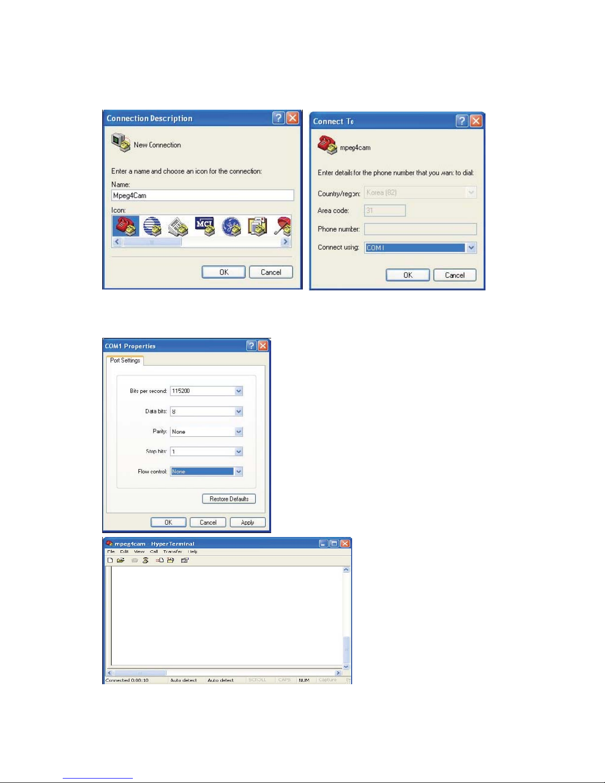
68
3. Configure the parameters as shown below:
You can see real-time messages
generated by the camera operating
system which can be recorded by
going to "Transfer" and clicking
"Capture Text." In case of a camera
malfunction, you can record this log
should the technical support team ask
for the information.
Page 69

69
Appendix C: Troubleshooting
This appendix provides useful information to help you to resolve any difficulty you might have with
your Pro Series Network Camera. Fault symptoms, possible causes and remedial actions are
provided within a quick reference table.
PINGing Your IP address
By sending a packet to the specified address and waiting for a reply, the PING (packet Internet
grouper) can determine whether a specific IP address is accessible. It also provides a particularly
useful method for confirming addressing conflicts with your Pro Series Network Camera on the network.
After disconnecting your camera, follow the instructions below in association with Symptoms, Possible
Causes and Remedial Actions and run the PING utility to troubleshoot TCP/IP problems on your
network.
1. Start a DOS window
2. Type ping x.x.x.x, where x.x.x.x is the IP address of the camera.
3. The subsequent replies will provide an explanation as to the cause of the problem. Replies
can be interpreted as defined in the table below:
PING reply
Interpretation and recommendation
bytes = 32 time = 2 ms
The IP address is already used and cannot be used again.
You must obtain a new IP address.
Destination host
unreachable
MPEG4 Network Camera is not accessible within your
subnet. You must obtain a new IP address.
Request timed out
This IP address is not used by anyone and is available for
use with your Pro Series Network Camera.
Symptoms, Possible Causes and Remedial Actions
Symptoms
Possible
Causes
Remedial Actions
The camera
cannot be
accessed
The IP address
is already used
by another
device
1. Disconnect your camera from the network.
2. Run the PING utility (as described in "PINGing
Your IP Address").
from a Web
browser
The IP address
is located within
a different
subnet
Run the PING utility (as described in "PINGing Your IP
Address"). If the utility returns "no response" or similar,
the diagnosis is probably correct — you should then
proceed as follows:
In Windows 95/98 or Windows 2000/XP/Vista, check that
the IP address for your camera is within the same
subnet as your workstation:
1. Click "Start," "Settings," "Control Panel" and
"Network."
2. Specify the TCP/IP adapter and click on "Properties."
In Properties, click "IP address."
3. Check that the first 3 numbers within the IP address of
Page 70

70
your camera match the first 3 of your workstation.
If not, your camera may be on a different subnet and the
IP address cannot be set from this workstation. You
must set the IP address for the camera from a
workstation on the same subnet.
Other
networking
problems
Trying replacing your network cable. Test the network
interface of the product by connecting a local computer
to the unit, using a standard crossover (hub-to-hub)
cable. If the above actions don’t resolve the problem, the
camera maybe faulty. In this case, try to localize the
problem by connecting the camera to the serial port of a
local computer, using the RS-232 cable.
The Power
LED is not
constantly lit
Faulty power
supply
Verify that you are using the provided power supply.
The Network
LED is off
Faulty cabling
1. To verify that the cables are functional, PING the
address of a known existing unit on your network.
2. If the cabling is okay and your network is reachable,
you should receive a reply similar to this: . . . bytes = 32
time = 2 ms,
The Operating
Status LED is
off
Faulty
connection
Verify that the power source is properly connected.
The camera
works
locally, but not
externally
Firewall
protection
Default routers
required The
Internet site’s
too heavily
loaded
Check the Internet firewall with your system manager.
Check if you need to configure the default router
settings. Configure the camera to upload your video
images to an FTP server or an ISP.
A series of
broad,
vertical white
lines appears
across the
image
The CCD
sensor
becomes
overloaded
when the light
is too bright, as
with reflected
sunlight
Direct exposure to extreme sunlight or halogen light may
cause serious damage to the CCD sensor. Re-position
your camera into a more shaded location immediately.
NOTE: Damage caused to a Pro Series Network
Camera through over-exposure to direct sunlight or
halogen light is not covered under the product warranty.
Bad focus
Focus has not
been correctly
adjusted
Adjust the camera manually until the image appears
clear.
Page 71

71
Noisy
images
Video images
may be noisy if
you are using
the camera in a
very low light
environment or
the bit
rate/quality is
set to very low
values
Improve the lighting conditions. If this doesn’t help and
the lighting conditions within the installation area can not
be improved, consider replacing the basic lens with a
more sensitive lens. Set the quality/bit rate to a higher
value.
Bad-quality
video
The display
properties are
incorrectly
configured for
your desktop
The camera is
not focused
correctly
Open the display properties on your desktop and
configure your display to show at least 65,000 colors;
i.e., at least 16-bit.
NOTE: Using only 16 or 256 colors on your computer
will produce dithering artifacts in the image. Adjust the
camera lens manually.
NOTE: If you still have a problem with your camera after following the above recommendations,
contact your dealer or check the WEBVIEW web site: http://www.networkipcam.com
.
Appendix D: Utilizing IP Addresses on a Local Network
Introduction
Access to the Internet is achieved via Internet IP addresses. Currently, IP addresses are limited.
There are five classes of networks, and each network contains IP addresses. A network can only hold
a limited number of IP addresses, and the number of IP addresses depends on the network class.
The five classes are labeled "A" through "E," with the most common one being the "C"-class network.
IP Construction and Network Class
IP Construction
xxx X1 xxx X2 xxx X3 xxx X4
(xxx: 0-255) e.g.,
192.168.1.1
Network Class A Class: A network that contains IP addresses from 0 to 127 at room "X1." Network
ID: X1Host ID: X2, X3, X4 There are 128 A-Class networks in the world.
B Class: A network that contains IP addresses from 128 to 172 at room "X1." Network ID: X1, X2Host
ID: X3, X4There are 65,534 B-Class networks in the world.
C Class: A network that contains IP addresses from 192 to 223 at room "X1." Network
ID: X1, X2, X3Host ID: X4 The most common network; there are 2,097,152 C-class
networks in the world.
D Class: A network that contains IP addresses from 224 to 239 at room "X1." D-class networks are
used for multicasting, and are not allowed for common use.
E Class: A network that contains IP addresses from 240 to 255 at room "X1." E-class networks are
reserved.
Page 72

72
C-Class Networks Features of
Addresses
IP address: The three-digit number in room "X4" is for the Host ID. The number range is from 0 to 255.
Among the numbers, 0 is used for Network ID, 1 is used for Router IP (gateway address)and 255 is
used for a broadcast address. The numbers from 2 to 244 are IP addresses that can be assigned to a
Pro Series Network Camera, PC, etc.
Network ID: Identifies a network. Generally the first number assigned is Network ID.
Gateway address: The IP address of the router for connecting the Internet and a local network.
Broadcast address: The IP address for broadcasting. All devices connected on a local network have
the same broadcast address.
Subnet mask: Divides a local network into two remote networks and shows the IP quantity in a certain
network. The number used as a subnet mask is limited: 0, 4, 8, 16, 32, 64, 128.
Network Configuration
1. To use as one network
Network ID: xxx.xxx.xxx.0
Gateway Address: xxx.xxx.xxx.1
Subnet Mask: 255.255.255.0
Broadcast Address: xxx.xxx.xxx.255
IP addresses: xxx.xxx.xxx.2 - xxx.xxx.xxx.254
2. To use as two sub-networks (1/2 + 1/2)
Sub-Network ID: xxx.xxx.xxx.0
Gateway Address: xxx.xxx.xxx.1
Subnet Mask: 255.255.255.128
Broadcast Address: xxx.xxx.xxx.127
IP addresses: xxx.xxx.xxx.2 - xxx.xxx.xxx.126
Sub-Network ID: xxx.xxx.xxx.128
Gateway Address: xxx.xxx.xxx.129
Subnet Mask: 255.255.255.128
Broadcast Address: xxx.xxx.xxx.255
IP addresses: xxx.xxx.xxx.130 -xxx.xxx.xxx.254
3. To use as three sub-networks (1/4 + 1/4 + 1/2)
Sub-Network ID: xxx.xxx.xxx.0
Gateway Address: xxx.xxx.xxx.1
Subnet Mask: 255.255.255.192
Broadcast Address: xxx.xxx.xxx.63
IP addresses: xxx.xxx.xxx.2 - xxx.xxx.xxx.62
Sub-Network ID: xxx.xxx.xxx.64
Gateway Address: xxx.xxx.xxx.65
Subnet Mask: 255.255.255.192
Broadcast Address: xxx.xxx.xxx.127
IP addresses: xxx.xxx.xxx.66 - xxx.xxx.xxx.126
Sub-Network ID: xxx.xxx.xxx.128
Page 73

73
Gateway Address: xxx.xxx.xxx.129
Subnet Mask: 255.255.255.128
Broadcast Address: xxx.xxx.xxx.225
IP addresses: xxx.xxx.xxx.130 -xxx.xxx.xxx.256
4. To use as four sub-networks (1/4 + 1/4 + 1/4 + 1/4)
Sub-Network ID: xxx.xxx.xxx.0
Gateway Address: xxx.xxx.xxx.1
Subnet Mask: 255.255.255.192
Broadcast Address: xxx.xxx.xxx.63
IP addresses: xxx.xxx.xxx.2 - xxx.xxx.xxx.62
Sub-Network ID: xxx.xxx.xxx.64
Gateway Address: xxx.xxx.xxx.65
Subnet Mask: 255.255.255.192
Broadcast Address: xxx.xxx.xxx.127
IP addresses: xxx.xxx.xxx.66 - xxx.xxx.xxx.126
Sub-Network ID: xxx.xxx.xxx.128
Gateway Address: xxx.xxx.xxx.129
Subnet Mask: 255.255.255.192
Broadcast Address: xxx.xxx.xxx.191
IP addresses: xxx.xxx.xxx.130 -xxx.xxx.xxx.190
Sub-Network ID: xxx.xxx.xxx.192
Gateway Address: xxx.xxx.xxx.193
Subnet Mask: 255.255.255.192
Broadcast Address: xxx.xxx.xxx.255
IP addresses: xxx.xxx.xxx.194 -xxx.xxx.xxx.254
Appendix E: Updating Firmware
CAUTION: The process for updating current firmware is already installed in your camera. If you begin
the process, follow the manual instructions. During the process, do not disconnect the network or
power source, and avoid any physical shock to the camera. Otherwise, the camera can be
seriously damaged and fail to function properly. If firmware fails to update, or if the camera does
not operate properly after a firmware update, contact your local dealer.
Identify the Version of Firmware
You can identify the version of the camera’s firmware on the System Configuration page. (You can
check the version of your camera firmware first and then try to update.) To check the present version of
firmware, go to the camera’s homepage and click "Administrator Tools"; then go to the System
Configuration page and check the version of the firmware.
Download New Firmware
You can download the latest firmware software through the Internet at the WEBVIEW support Web
site: www.networkipcam.com
.
Page 74
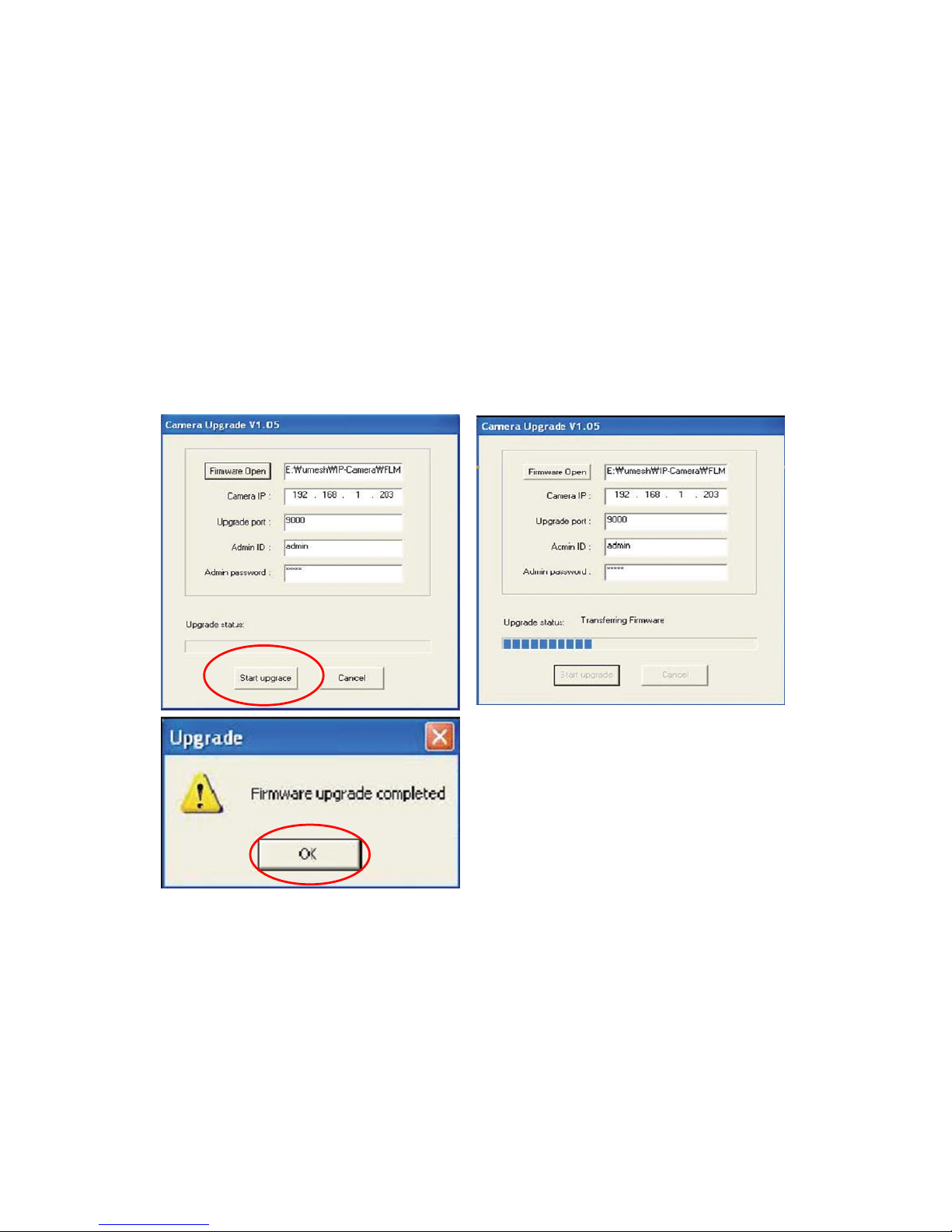
74
Install New Firmware
Camera firmware can be upgraded via the LAN or remotely over the Internet.
1. Confirm that the camera is connected to your PC. (As long as you can access your camera
homepage, you can process an upgrade.)
2. Execute the newly updated firmware and select the firmware file via the "Firmware Open"
button.
3. Enter the camera’s IP address, upgrade port number, admin ID and password configured on
the Network Configuration page. Then click on "Start upgrade." You may see the upgrading
status. Upgrading levels are divided into four steps, from "Transferring Firmware" to "Verifying
flash memory." (Each step is indicated on a progress bar.)
4. When completed upgrading, a message appears that indicates the upgrade has been
completed. Click the "OK" button.
NOTE: If you receive the warning "INVALID HEADER MARKER" during the firmware upgrade, restart
your computer in safe mode with networking support and repeat the procedure.
Page 75
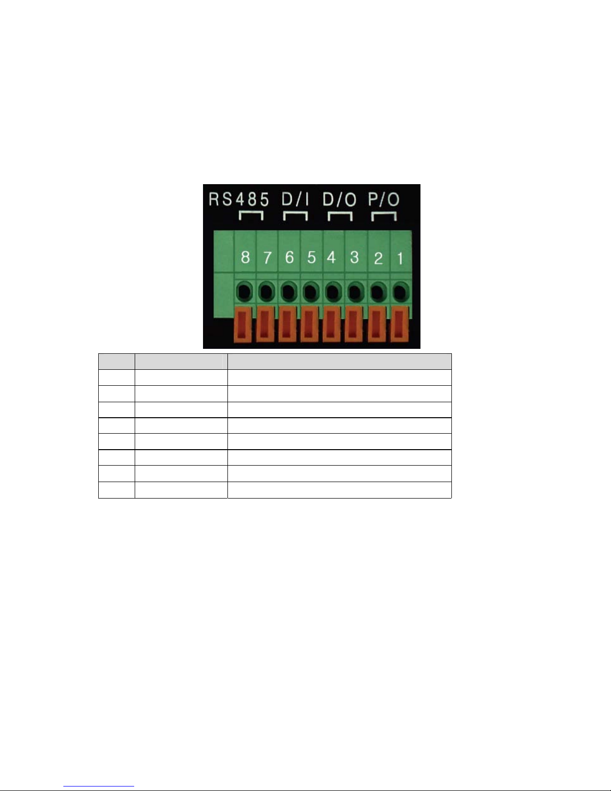
75
Appendix F: The I/O Connector (MPEG4 Cameras)
The I/O Connector provides the physical interface to a digital output and a single digital, photo-coupled
input that is used for connecting a variety of external alarm devices to the Pro Series Network Camera,
including infrared sensors, switches and alarm relays. In combination with the configurable alarm
facilities, you can quickly develop a variety of security applications that are triggered on time- or
alarm-based events.
No. Function Description
1 Power GND (-) Power for the external I/O devices (-)
2 Power DC12V (+) Power for the external I/O devices (+)
3 Digital Out (+) Output for the external output devices (+)
4 Digital Out GND (-) Output for the external output devices (-)
5 Digital In (+) Input to the external Input devices (+)
6 Digital In GND (-) Input to the external input devices (-)
7 RS-485 (+) Not in use
8 RS-485 (-) Not in use
1-2 PIN
To supply external devices with power. PIN 1 is connected to the GND terminal of a device’s power
and PIN 2 is connected to the positive (+) terminal. However, the external device should be less than
12 V DC and 200 mA. This is a permanent 12 V DC power source.
3-4 PIN
To supply external devices with power. PIN 4 is connected to the GND terminal of a device’s power
and PIN 3 is connected to the positive (+) terminal. However, the external device should be less than
12 V DC and 200 mA. Power is only provided if an alert state has occurred in the Event Trigger
Configuration (see section 6.5).
5-6 PIN
PIN 5 and PIN 6 are connected to the signal output terminal of an external input device, such as an IR
or alarm sensor.
Page 76
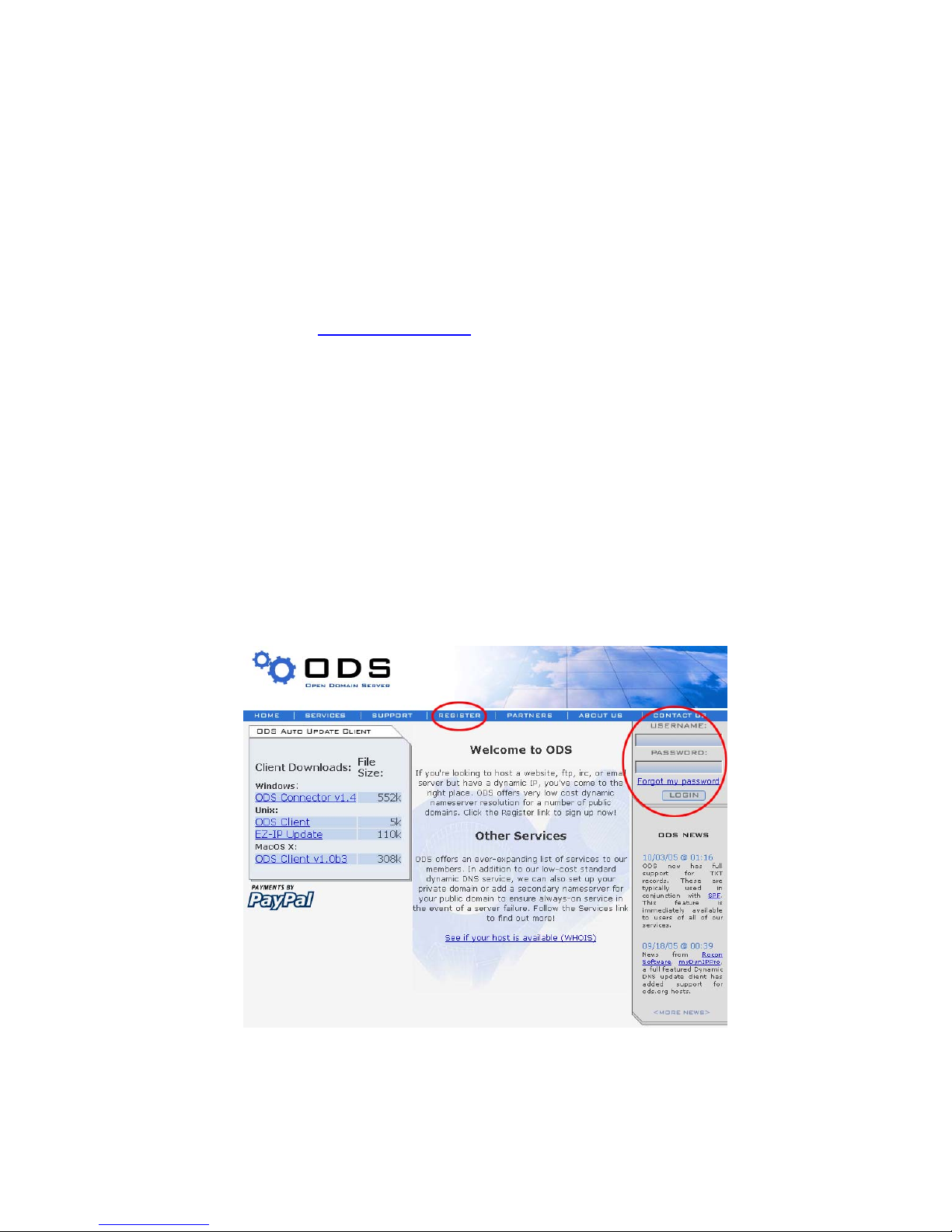
76
Appendix G: Dynamic Domain Name System (DDNS)
Your Internet service provider (ISP) provides you with at least one IP address that you use to
connect to the Internet. The address you get may be static, meaning it never changes, or dynamic,
meaning it’s likely to change periodically. Just how often it changes depends on your ISP. A dynamic
IP address complicates remote access since you may not know what your current WAN IP address
is when you want to access your network over the Internet. The solution to the dynamic IP address
problem comes in the form of a dynamic DNS service.
The Internet uses DNS servers to look up domain names and translates them into IP addresses.
Domain names, such as www.networkipcam.com
, are just easy-to-remember aliases for IP addresses.
A dynamic DNS service is unique because it provides a means of updating your IP address so that
your listing will remain current when your IP address changes. There are several excellent DDNS
services available on the Internet and, best of all, some of them free to use. The WEBVIEW Network
Cameras support the DDNS service provided by www.DynDNS.org. You’ll need to register with the
service and set up the domain name of your choice to begin using it. Please refer to the homepage or
the service for detailed instructions.
A DDNS service works by uploading your WAN IP address to its servers periodically. Your
gateway/router may support DDNS directly, in which case you can enter your DDNS account
information into your router and it will update the DDNS servers automatically when your IP address
changes. Consult your router’s documentation for more information. If your router does not support
DDNS, you can run a small client utility on any PC on your network that will perform the updating. The
client utility is usually provided for free by the service. Check the service’s Web page for further
information, terms and conditions.
How to Use the ODS DDNS Service
1. Go to the ODS homepage (www.ods.org).
2. If you didn’t register your ID, select the “Register” menu and register your ID/password. Or, just log
in with a registered ID/password.
Page 77
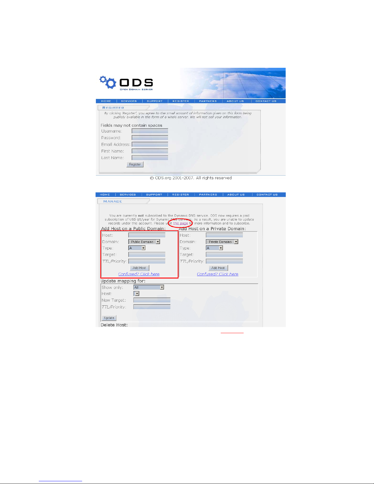
77
3. After you register with an ID/password normally, you can see the “Manage” page.
NOTE: ods.org service is not for free. If you did not paid, click this page
and follow instructions to pay
for it in advance, or you can’t utilize the service.
3. If you want to use a normal DDNS service among many services, you should fill in the open fields
and then click the “Add Host” button.
. Host: Enter the name you want.
. Domain: Select a domain you want.
. Type: Select “A” (“A” is normal)
. Target: Enter the initial IP of the equipment (or any IP address in the form “xxx.xxx.xxx.xxx”)
. TTL Priority: Do NOT select. This is optional.
If you want to select “Webview.ods.org” for a domain name, enter “Webview” in the “Host” field and
Page 78
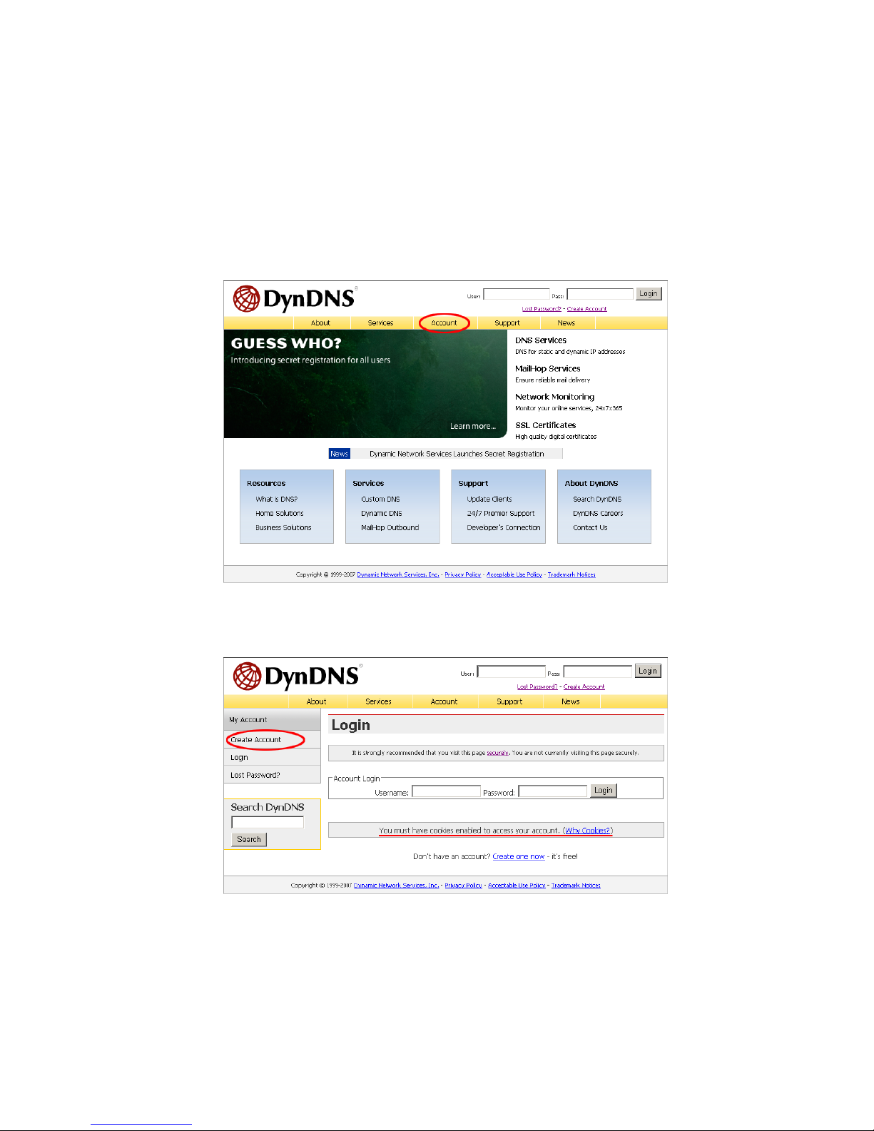
78
then select ods.org for the domain. Otherwise, refer to the premium service.
NOTE: After completing the ODS DDNS settings, complete the DDNS registration on network
configuration of administrator menu of the camera. Refer to Section 6.3.
How to Use the DynDNS DDNS Server
1. Go to the DynDNS homepage (www.dyndns.org or www.dyndns.com).
2. If you didn’t register your ID, click “Create Account” and register your ID. Or, just log in with a
registered ID.
NOTE: Read and follow instruction about cookies!
Page 79
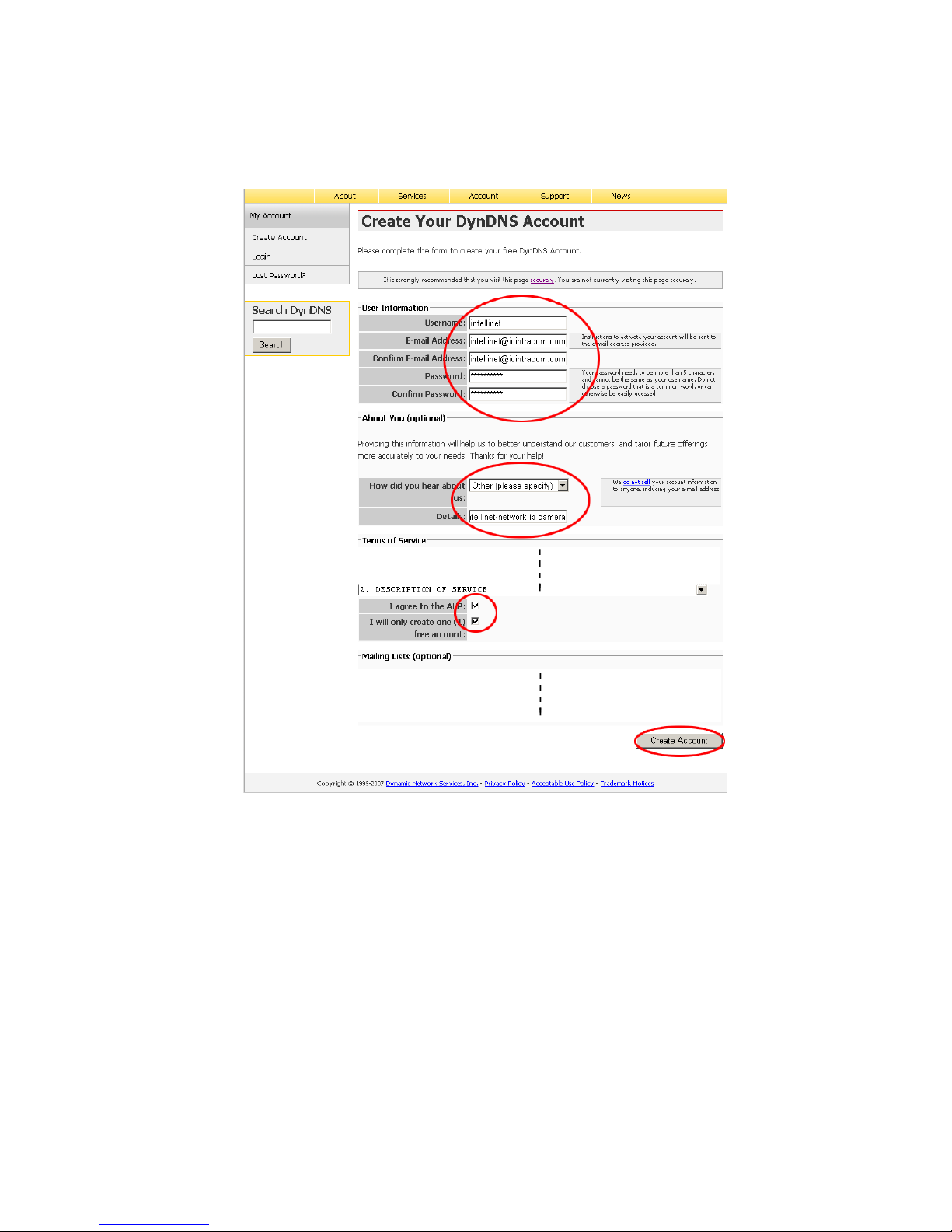
79
3. Fill your information in red circles and press “Create Account” button.
4. You will see account created message as follows.
Page 80
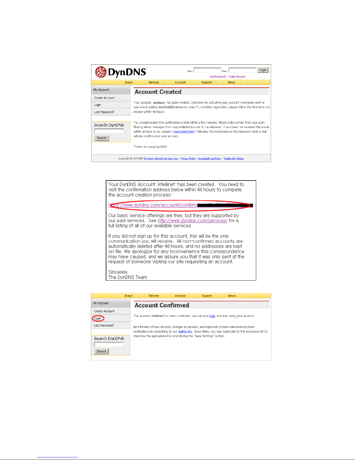
80
5. You will get a e-mail like bellows, then click on URL in red circle.
NOTE: Confirm in 48 hours or your account will be deleted from the DDNS server.
6. Click on “Login” and log in with your user ID and password.
7. Click on Services, DNS Services, Dynamic DNS and Create Hosts subsequently.
Page 81
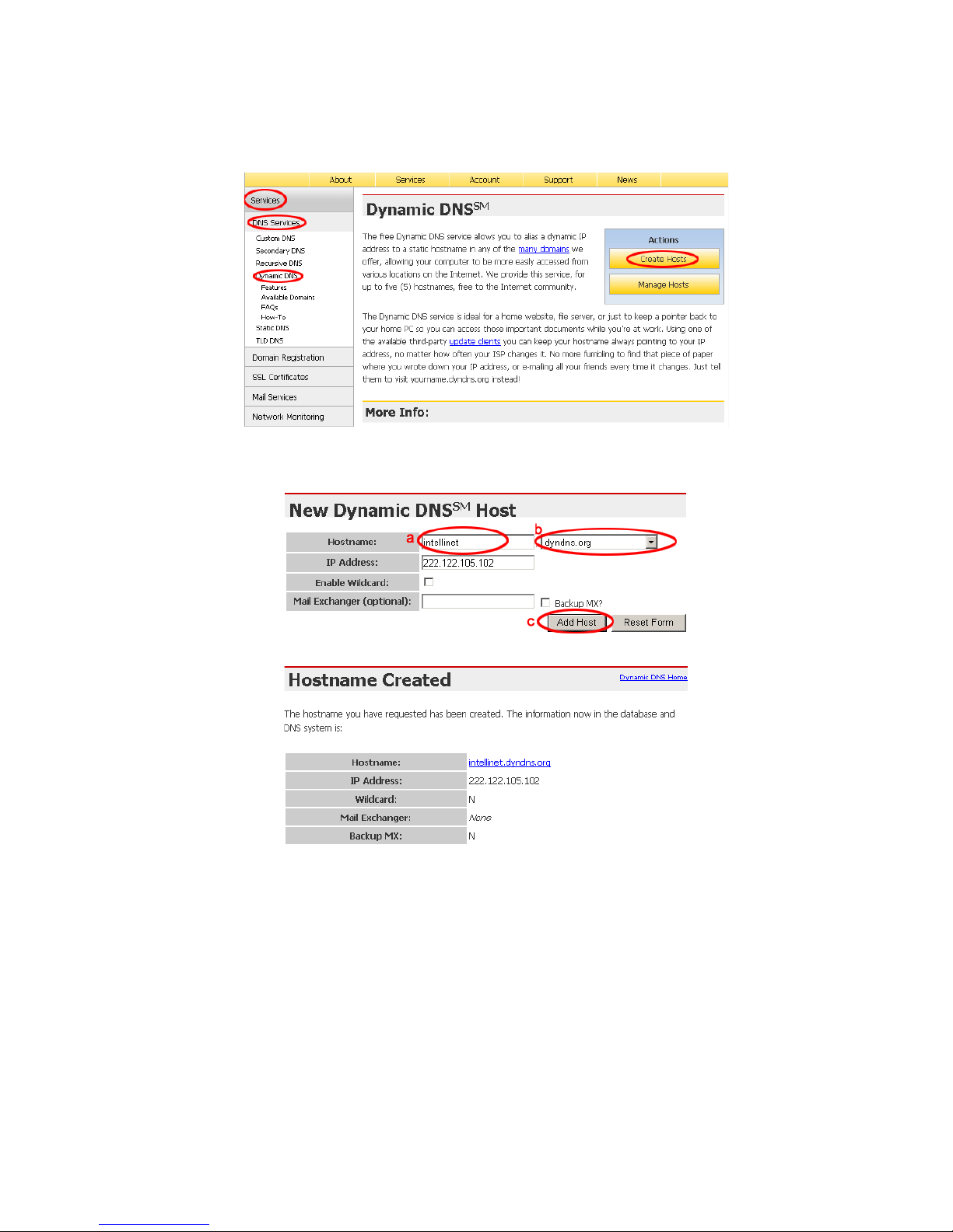
81
8. Fill Hostname(a) you want in, select domain name(b) you want and press “Add Host”(c).
The other items are okay as they are. For the detailed about each field, refer to the FAQ page.
5. After successful registration, registered information will be shown as bellows.
NOTE: After having registered completely with DDNS server, do the DDNS settings for the camera.
DDNS Registration for the Pro Series Network Camera
1. After setting up ODS or DynDNS, open network configuration page of administrator menu.
2. At least one of 1st and 2nd DNS Server Address should be predefined and it should be in service
normally.
Page 82
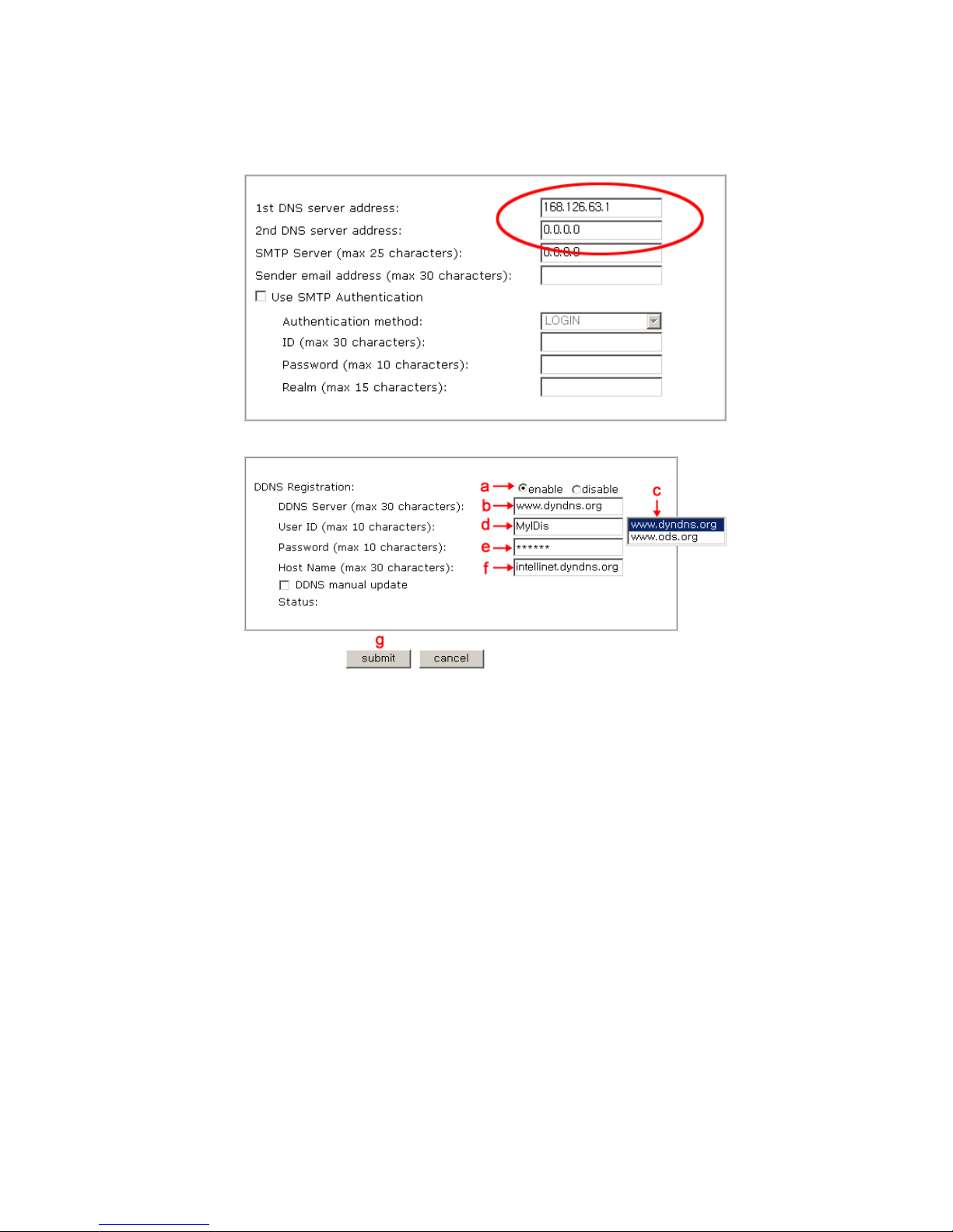
82
3. In the DDNS Registration section,
a. click “enable”,
b. click on the DDNS Server Box,
c. select the DDNS server (ODS or DynDNS) you want.
d. fill your registered user ID in.
e. fill your registered password in
g. press submit button
NOTE: Fill in with full domain name like “intellinet.dyndns.org”.
NOTE: Before DDNS settings, your ID/password and domain name should have registered in the ODS
or DynDNS DDNS service.
3. If registration is successful, you may see “Registration Success” in the “Status” area after several
seconds, otherwise check your registered information again or network connection status!
4. After having registered successfully, you can connect to the camera by a domain name that you
registered.
Page 83
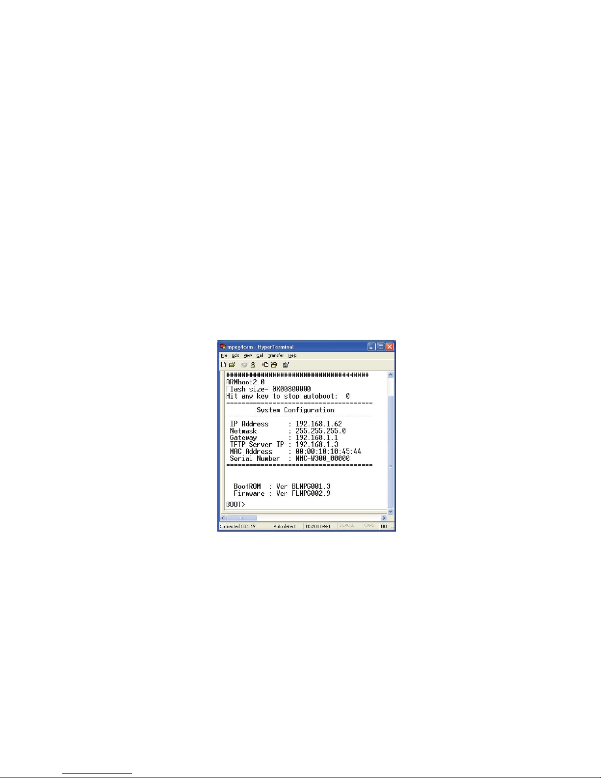
83
Appendix H: Reinstating the Factory Default Settings
This information details how to set the default settings for the Pro Series Network Camera. In certain
circumstances, it may be necessary to restart or reinstate the factory default settings for your camera.
This is done by pressing the Reset button or by using HyperTerminal settings.
Pressing the Rese t B u tton
1. Using a paper clip or any sharp pin, press the Reset button on the back of the camera.
2. Switch off the camera by disconnecting the power cable.
3. While pressing the Reset button, reconnect the power supply cable. Keep the Reset button
pressed until the green Operating Status LED blinks three times (this may take 10 to 15
seconds). Release the Reset button.
Using HyperTerminal
1. Run "HyperTerminal" (see 4.3.1).
2. Supply power to the camera.
3. After a few moments, the countdown begins with the prompt "Press any key to stop auto
booting within 3 seconds..." Press any key to display the screen below.
When you enter "Set," the administrator ID and password reinstate as factory default "admin."
NOTE: Reinstating the original default settings will cause all parameters (including IP address) to be
reset.
Factory default settings
Administrator ID: admin Administrator password: admin
Guest ID: guest Guest password: guest
IP address: 192.168.1.221
Subnet mask address: 255.255.255.0
Gateway address: 192.168.1.1
Server IP address: 192.168.1.5
Page 84

84
Appendix I: Glossary of Terms
ActiveX -A control (or set of rules) used by a browser. ActiveX controls are often downloaded and
installed automatically as required.
ARP -Address Resolution Protocol. A method for finding a host's Ethernet address from its Internet
address. The sender broadcasts an ARP packet containing the Internet address of another host and
waits for it (or some other host) to send back its Ethernet address. Each host maintains a cache of
address translations to reduce delay and loading. ARP allows the Internet address to be independent
of the Ethernet address, but it only works if all hosts support it. The ARP command can be used to set
the IP addresses for your product.
CGI -Common Gateway Interface. A standard for running external programs from a World Wide Web
HTTP server. CGI specifies how to pass arguments to the executing program as part of the HTTP
request. It also defines a set of environment variables. Commonly, the program will generate some
HTML that will be passed back to the browser, but it can also request URL redirection. Basically, it’s a
set of rules (or a program) that allows a Web server to communicate with other programs.
DSL - Digital Subscriber Loop. A family of digital telecommunications protocols designed to allow
high-speed data communication over the existing copper telephone lines between end- users and
telephone companies.
DHCP -A protocol that provides a means to dynamically allocate IP addresses to computers on a local
area network. The system administrator assigns a range of IP addresses to a DHCP, and each client
computer on the LAN has its TCP/IP software configured to request an IP address from the DHCP
server. The request and grant process uses a lease concept with a controllable time period.
Ethernet -A widely used networking standard.
Firewall -A virtual barrier between a LAN (Local Area Network) and other networks; e.g., the
Internet.
Frame Grabber Card - Plug-in hardware for "grabbing" images.
FTP -A client-server protocol that allows a user on one computer to transfer files to and from another
computer over a TCP/IP network. Also, the client program the user executes to transfer files. It is
defined in STD 9, RFC 959.
HTML -A markup language used to structure text and multimedia documents and to set up
hypertext links between documents, used extensively on the World Wide Web.
HTTP - A protocol used to request and transmit files, especially Web pages.
Intranet -A privately maintained computer network that can be accessed only by authorized
persons, especially members or employees of the organization that owns it.
IP - Internet Protocol. The network layer for the TCP/IP protocol suite widely used on Ethernet
networks, defined in STD 5, RFC 791. IP is a connectionless, best-effort packet switching protocol. It
provides packet routing, fragmentation and re-assembly through the data link layer.
IP number (address) -A unique number used by a computer on the network to allow it to be
identified and found.
JPEG -A standard image format, used widely for photographs. Also known as JPG.
LAN - Local Area Network. A data communications network which is geographically limited
(typically to a 1 km radius), allowing easy interconnection of terminals, microprocessors and
computers within adjacent buildings. Ethernet and FDDI are examples of standard LANs.
PING -A protocol that sends a message to another computer and waits for acknowledgment, often
used to check if another computer on a network is reachable.
PPP - Point to Point Protocol. A method allowing one computer to connect to another, usually via a
modem over a phone line.
Page 85

85
Protocol - A set of formal rules describing how to transmit data, especially across a network.
Low-level protocols define the electrical and physical standards to be observed, bit-and
byte-ordering and the transmission and error detection and correction of the bit stream. High-level
protocols deal with the data formatting, including the syntax of messages, the terminal to computer
dialogue, character sets, sequencing of messages, etc.
SMTP - Simple Mail Transfer Protocol.
TCP/IP - Transmission Control Protocol/Internet Protocol. The wide-area-networking protocol that
makes the Internet work. TCP/IP is used on many networks, including the Internet. TCP keeps track
of the individual packets of information and IP contains the rules for how the packets are actually
sent and received.
URL - Uniform Resource Locator. An "address" on the network.
WAN - Wide Area Network. A communications network that uses such devices as telephone lines,
satellite dishes or radio waves to span a larger geographic area than can be covered by a LAN.
Wizard -A program designed specifically to guide the user through a procedure. Typically used for
installation and configuration. InstallShield Wizard is required to download ActiveX manually.
Appendix J: Product Specifications
Pro Series CCD Network Camera
MPEG4/M-JPEG Dual Mode, Sony Super HAD CCD, Day/Night, 2 Way Audio, PoE, NTSC/PAL
Model : MNC-L200 Standard Version
MNC-L200TDN True Day & Night Version
Specifications
Standards
• IEEE 802.3 (10Base-T Ethernet)
• IEEE 802.3u (100Base-TX Fast Ethernet)
• IEEE 802.3af (Power over Ethernet)
General
• 32-bit ARM9 RISC CPU
• 16 MByte video frame buffer
• 8 Mbyte flash memory
• 32 Mbyte SDRAM
• Supported image resolutions: NTSC D1 (720 x 480), PAL D1 (720 x 576), VGA, CIF
• Audio support:
- Full duplex
- Bandwidth: 300 Hz to 3.4 KHz
- Audio input: 3.5 mm / 1.8" microphone input jack
- Audio output: 3.5 mm / 1.8" speaker output jack
• Protocols supported: TCP/IP, UDP, HTTP, FTP, SMTP, DHCP, DNS, ARP, ICMP, RTSP, RTC
• Certifications: FCC Class B, RF: EN300328, EMC: EN301489-1/-7, Safety: EN60950-1
Image Sensor and Lens Specification
• 1/3" SONY Super HAD CCD sensor
• S/N ratio: > 48 dB
• Video output: 1.0 Vp-p (75 Ohms, composite)
• Automatic white balance control
Page 86

86
• Image Control, Brightness, Contrast, Saturation, Hue
•
Min. Illumination 0.1 Lux / 0.001 Lux for TDN
• Electronic shutter: 1/60 – 1/10.000 sec.
• Replaceable standard 1/3" CS mount lens
• 6mm Fixed Iris Lens / Vari-Focal DC Control Auto Iris Lens (3.5mm-8.0mm) for TDN
• Maximum relative aperture F1.8
LEDs
• Power
• Network connection
• Camera operation
Environmental
• Dimensions: 87 (W) x 158 (L) x 45 (H) mm (3.4 x 6.2 x 1.8 in.)
• Weight: 325g
• Operating temperature: 0 – 50°C (32 – 122°F)
• Operating humidity: 10 – 95% RH, non-condensing
• Storage temperature: 0 – 60°C (0 – 149°F)
Power
• External power adapter: 12 V DC, 1.5 A
• Power consumption: 3.0 Watts (maximum)
System Requirements
• Windows 2000, XP, Vista, Linux, Mac OS X
• Computer with network connection
• Web browser support:
- MS Internet Explorer 5.0 or higher (ActiveX + Java)
- Mozilla 1.x, Mozilla Firefox (Java)
- Netscape Navigator 6.0 or higher (Java)
- Opera (Java)
- Safari (Java)
- Konqueror (Java)
Package Contents
• Pro Series Network Camera
• User manual
• External power adapter
• Software CD
Pro Series Wireless Network Camera
Wireless G MPEG4/M-JPEG Dual Mode, Sony Super HAD CCD, Day/Night, 2 Way Audio, PoE,
NTSC/PAL
Model: MNC-W200 Standard Version
Model: MNC-W200TDN True Day & Night Version
Specifications
Standards
• IEEE 802.11b (11 Mbps Wireless LAN)
• IEEE 802.11g (54 Mbps Wireless LAN)
Page 87

87
•
IEEE 802.3 (10Base-T Ethernet)
• IEEE 802.3u (100Base-TX Fast Ethernet)
• IEEE 802.3af (Power over Ethernet)
General
• 32-bit ARM9 RISC CPU
• 16 MByte video frame buffer
• 8 Mbyte flash memory
• 32 Mbyte SDRAM
• Supported image resolutions: NTSC D1 (720 x 480), PAL D1 (720 x 576), VGA, CIF
• Audio support:
- Full duplex
- Bandwidth: 300 Hz to 3.4 KHz
- Audio input: 3.5 mm / 1.8" microphone input jack
- Audio output: 3.5 mm / 1.8" speaker output jack
• Protocols supported: TCP/IP, UDP, HTTP, FTP, SMTP, DHCP, DNS, ARP, ICMP, RTSP, RTC
• Certifications: FCC Class B, RF: EN300328, EMC: EN301489-1/-7, Safety: EN60950-1
•
Data rates:
- IEEE 802.11b (11 Mbps, 5.5 Mbps, 2 Mbps, 1 Mbps)
- IEEE 802.11g (54 Mbps, 48 Mbps, 36 Mbps, 24 Mbps, 18 Mbps, 12 Mbps, 9 Mbps, 6 Mbps)
• Data encryption: WEP (64-bit & 128-bit), WPA- and WPA2-PSK (with TKIP and AES
• Antenna: single detachable dipole antenna with RP-SMA connector, 2 dBi gain
• Operation modes: Infrastructure, Ad Hoc
• Preamble modes: long, short, auto
Image Sensor and Lens Specification
•
1/3" SONY Super HAD CCD sensor
• S/N ratio: > 48 dB
• Video output: 1.0 Vp-p (75 Ohms, composite)
• Automatic white balance control
• Image Control, Brightness, Contrast, Saturation, Hue
• Min. Illumination 0.1 Lux / 0.001 Lux for TDN
• Electronic shutter: 1/60 – 1/10.000 sec.
• Replaceable standard 1/3" CS mount lens
• 6mm Fixed Iris Lens / Vari-Focal DC Control Auto Iris Lens (3.5mm-8.0mm) for TDN
• Maximum relative aperture F1.8
LEDs
• Power
• Network connection
• Camera operation
Environmental
• Dimensions: 87 (W) x 158 (L) x 45 (H) mm (3.4 x 6.2 x 1.8 in.)
• Weight: 340g
• Operating temperature: 0 – 50°C (32 – 122°F)
• Operating humidity: 10 – 95% RH, non-condensing
Page 88

88
•
Storage temperature: 0 – 60°C (0 – 149°F)
Power
• External power adapter: 12 V DC, 1.5 A
• Power consumption: 3.0 Watts (maximum)
System Requirements
• Windows 2000, XP, Vista, Linux, Mac OS X
• Computer with network connection
• Web browser support:
- MS Internet Explorer 5.0 or higher (ActiveX + Java)
- Mozilla 1.x, Mozilla Firefox (Java)
- Netscape Navigator 6.0 or higher (Java)
- Opera (Java)
- Safari (Java)
- Konqueror (Java)
Package Contents
• Pro Series Wireless Network Camera
• User manual
• External power adapter
• Software CD
• Camera Bracket
Pro Series Night Vision Network Camera
MPEG4/M-JPEG Dual Mode, Sony Super HAD CCD, Night Vision with IR Lens, 2 Way Audio, PoE,
NTSC/PAL
Model: MNC-L200IR
Model: MNC-W200IR – Wireless G
Specifications
Standards
•
IEEE 802.3 (10Base-T Ethernet)
• IEEE 802.11b/g (for MNC-W200IR)
• IEEE 802.3u (100Base-TX Fast Ethernet)
• IEEE 802.3af (Power over Ethernet)
General
•
32-bit ARM9 RISC CPU
• 16 MByte video frame buffer
• 8 Mbyte flash memory
• 32 Mbyte SDRAM
• Supported image resolutions: NTSC D1 (720 x 480), PAL D1 (720 x 576), VGA, CIF
• Audio support:
- Full duplex
- Bandwidth: 300 Hz to 3.4 KHz
- Audio input: 3.5 mm / 1.8" microphone input jack
- Audio output: 3.5 mm / 1.8" speaker output jack
• Protocols supported: TCP/IP, UDP, HTTP, FTP, SMTP, DHCP, DNS, ARP, ICMP, RTSP, RTC
• Certifications: FCC Class B, RF: EN300328, EMC: EN301489-1/-7, Safety: EN60950-1
Wireless Communication
•
Data rates:
- IEEE 802.11b (11 Mbps, 5.5 Mbps, 2 Mbps, 1 Mbps)
Page 89

89
- IEEE 802.11g (54 Mbps, 48 Mbps, 36 Mbps, 24 Mbps, 18 Mbps, 12 Mbps, 9 Mbps, 6 Mbps)
• Data encryption: WEP (64-bit & 128-bit), WPA- and WPA2-PSK (with TKIP and AES authentication)
• Antenna: single detachable dipole antenna with RP-SMA connector, 2 dBi gain
• Operation modes: Infrastructure, Ad Hoc
• Preamble modes: long, short, auto
Image Sensor and Lens Specification
•
1/3" SONY Super HAD CCD sensor
• 410K pixel array
• S/N ratio: > 48 dB
• Video output: 1.0 Vp-p (75 Ohms, composite)
• Automatic white balance control
• Image Control, Brightness, Contrast, Saturation, Hue
• Min. Illumination : 0 Lux with IR LED’s on
• Electronic shutter: 1/60 – 1/10.000 sec.
• Replaceable standard 1/3" CS mount lens
• 6mm Fixed Iris Lens, angular field of view 53˚
• Maximum relative aperture F1.8
LEDs
•
Power
• Network connection
• Camera operation
Environmental
•
Dimensions: 87 (W) x 158 (L) x 45 (H) mm (3.4 x 6.2 x 1.8 in.)
• Weight: 345g
• Operating temperature: 0 – 50°C (32 – 122°F)
• Operating humidity: 10 – 95% RH, non-condensing
• Storage temperature: 0 – 60°C (0 – 149°F)
Power
• External power adapter: 12 V DC, 1.5 A
• Power consumption: 3.0 Watts (maximum)
System Requirements
•
Windows 2000, XP, Vista, Linux, Mac OS X
• Computer with network connection
• Web browser support:
- MS Internet Explorer 5.0 or higher (ActiveX + Java)
- Mozilla 1.x, Mozilla Firefox (Java)
- Netscape Navigator 6.0 or higher (Java)
- Opera (Java)
- Safari (Java)
- Konqueror (Java)
Package Contents
•
Pro Series Night Vision Network Camera
• User manual
• External power adapter
• Software CD
• Camera Bracket
Page 90

90
Pro Series Digital PTZ Network Camera
MPEG4/M-JPEG Dual Mode, 2.0 Mega Pixel CMOS, 2 Way Audio, PoE, 5X Digital Zoom & Pan Tilt
Operation
Model: MNC-L100M20
Model: MNC-W100M20 – Wireless G
Specifications:
Standards
● IEEE 802.3 (10Base-T Ethernet)
● IEEE 802.3u (100Base-TX Fast Ethernet)
● IEEE 802.3af (Power over Ethernet)
● IEEE 802.11 b/g WLAN
General
● 32-bit ARM9 RISC CPU
● 16 MByte video frame buffer
● Image buffer: 200 frames (CIF)
● 8 MByte flash memory
● 32 MByte SDRAM
● Supported image resolutions: D1 (720 x 480), VGA (640 x 480), CIF (352 x 240)
● Video frame rate: max. 25 fps @ D1; 25 fps @ VGA; 25 fps @ CIF
● Audio support:
- Full duplex
- Bandwidth: 300 Hz~3.4 kHz
- Audio input: 3.5 mm / 1.8" microphone input jack
- Audio output: 3.5 mm / 1.8" speaker output jack
● Protocols supported: TCP/IP, UDP, HTTP, FTP, SMTP, DHCP, DNS, ARP, ICMP, RTSP, RTC
● Certifications: FCC Class B, RF: EN300328, EMC: EN301489-1/-7, Safety: EN60950-1
Image Sensor and Lens Specification
● 1/3.2" Micron Progressive Scan CMOS sensor
● 2.0 Mega Pixel resolution (1,668 H x 1,248 V)
● S/N ratio: 42.3 dB (max.)
● Shutter type: Electronic rolling shutter (ERS)
● Automatic defect correction, exposure, white balance, black reference, flicker avoidance and
color saturation
● Manual brightness, contrast, saturation, hue, sharpness control
● Manual white balance control
● Minimum illumination: 0.1 lux
● Focal length 6.0 mm, angular field of view 53 degree, object distance 1 m to infinity
LED’s
● Power
● Network connection
● Camera operation
Environmental
● Dimensions: 87 (W) x 158 (L) x 45 (H) mm (3.4 x 6.2 x 1.8 in.)
● Weight: 285g
● Operating temperature: 0 degree C~50degree C (32 ~122 degree F)
● Operating humidity: 20 ~80% RH, non-condensing
● Storage temperature: 0 ~60degree C (32~140degree F)
Power
● External power adapter: 12 V DC, 1.5 A
● Power consumption: 6.0 Watts (maximum)
Page 91

91
System Requirements
● Windows 2000, XP, Vista, Linux, Mac OS X
● Computer with network connection
● Web browser support:
- MS Internet Explorer 5.0 or higher (ActiveX + Java)
- Mozilla 1.x, Mozilla Firefox (Java)
- Netscape Navigator 6.0 or higher (Java)
- Opera (Java)
- Safari (Java)
- Konqueror (Java)
Package Contents
● Pro Series Digital PTZ Network Camera
● User manual
● External power adapter
● Software CD
● Camera Bracket
Vandal Dome Network Camera
MPEG4/M-JPEG Dual Mode, True Day/Night, Vandal & Tamper Proof Housing, Night Vision with
IR LED’s(for 300VTDNIR), NTSC/PAL
Model: MNC-300V : Standard
Model: MNC-300VTDNIR : True Day & Night with IR Night Vision
Specifications
Standards
•
IEEE 802.3 (10Base-T Ethernet)
• IEEE 802.3u (100Base-TX Fast Ethernet)
• IEEE 802.3af (Power over Ethernet)
• IP66 (Ingress Protection)
General
•
32-bit ARM9 RISC CPU
• 16 MByte video frame buffer
• 8 Mbyte flash memory
• 32 Mbyte SDRAM
• Supported image resolutions: NTSC D1 (720 x 480), PAL D1 (720 x 576), VGA, CIF
• Audio support:
- Full duplex
- Bandwidth: 300 Hz to 3.4 KHz
- Audio input: 3.5 mm / 1.8" microphone input jack
- Audio output: 3.5 mm / 1.8" speaker output jack
• IR distance : Max. 30M Effective 25M
• Protocols supported: TCP/IP, UDP, HTTP, FTP, SMTP, DHCP, DNS, ARP, ICMP, RTSP, RTC
• Certifications: FCC Class B, RF: EN300328, EMC: EN301489-1/-7, Safety: EN60950-1
Image Sensor and Lens Specification
•
1/3" SONY Super HAD CCD sensor
• S/N ratio: > 48 dB
• Video output: 1.0 Vp-p (75 Ohms, composite)
• Automatic white balance control
• Image Control, Brightness, Contrast, Saturation, Hue
• Min. Illumination 0.5 Lux / 0.00001 Lux for TDN
Page 92

92
•
Electronic shutter: 1/60 – 1/10.000 sec.
• Lens : 4.0~9.0mm Vari-focal Auto Iris Lens (DC Drive)
LED’s
•
Power
• Network connection
• Camera operation
Environmental
•
Dimensions: 160(D)mm*110mm(H) (6.29inch * 4.33inch)
• Weight: 990g (Bracket not included)
• Operating temperature: ㅡ10’C~+50’C
• Storage temperature: ㅡ10’C~+50’C
Power
•
External power adapter: 12 V DC, 2.0 A
• Power consumption: 4.0 Watts (maximum)
System Requirements
•
Windows 2000, XP, Vista
• Computer with network connection
• Web browser support:
- MS Internet Explorer 5.0 or higher (ActiveX)
- Netscape Navigator, Mozilla, Firefox, Opera (Java for JPEG only)
Package Contents
•
Vandal Dome Network Camera
• User manual
• External power adapter
• Software CD
Pro Series Network Video Server
MPEG4/M-JPEG Dual Mode, 2 Way Audio, PoE, NTSC/PAL
Model: MNS-202
Specifications
Standards
•
IEEE 802.3 (10Base-T Ethernet)
• IEEE 802.3u (100Base-TX Fast Ethernet)
• IEEE 802.3af (Power over Ethernet)
General
•
32-bit ARM9 RISC CPU
• 16 MByte video frame buffer
• 8 Mbyte flash memory
• 32 Mbyte SDRAM
• Supported image resolutions:
- PAL: D1 (720 x 576), VGA (640 x 576), CIF (352 x 288)
- NTSC: D1 (720 x 480), VGA (640 x 480), CIF (352 x 240)
• Audio support:
- Full duplex
- Bandwidth: 300 Hz to 3.4 KHz
Page 93

93
- Audio input: 3.5 mm / 1.8" microphone input jack
- Audio output: 3.5 mm / 1.8" speaker output jack
• Protocols supported: TCP/IP, UDP, HTTP, FTP, SMTP, DHCP, DNS, ARP, ICMP, RTSP, RTC
• Certifications: FCC Part 15, Subpart B Class A, CE Directive 89/336/EEC (EMC Directive)
PTZ Control
•
Selectable baud rate (2400, 4800, 9600 bps)
• Selectable ID (1 – 255)
• Supported protocols: Pelco D/P
• Supported cameras: HONEYWELL HRX-2000, VICON V1311RB-VPS, LG LPT-A100L, SAMSUNG
TECHWIN, SAMSUNG ELECTRONICS MRX-1000, INTER-M, DONGYANG UNITECH DRX302A and all
other cameras using Pelco-D and P
External IO
•
RS-485 port for PTZ control
• DC output for power supply to external device (12 V, 500 mA)
• Sensor input
• Alarm output
LEDs
•
Power
• Network connection
• On Air / Network Video Server Active
Environmental
•
Dimensions: 142 (W) x 145 (L) x 31 (H) mm (5.6 x 5.7 x 1.2 in.)
• Weight: 1.3 kg (2.8 lbs.)
• Operating temperature: 0 – 50°C (32 – 122°F)
• Operating humidity: 20 – 80% RH, non-condensing
• Storage temperature: 0 – 60°C (0 – 149°F)
System Requirements
•
Windows 2000, XP, Vista, Linux, Mac OS X
• Computer with network connection
• Web browser support:
- MS Internet Explorer 5.0 or higher (ActiveX + Java)
- Mozilla 1.x, Mozilla Firefox (Java)
- Netscape Navigator 6.0 or higher (Java)
- Opera (Java)
- Safari (Java)
- Konqueror (Java)
Power
• External power adapter: 12 V DC, 1.5 A
• Power consumption: 6.0 Watts (maximum)
Package Contents
•
Pro Series Network Video Server
• User manual
• External power adapter
• Software CD
Page 94

94
ٛ
WEBVIEW™ offers a complete line-up of network video products and solution. Ask
your local dealer for more information or visit www.networkipcam.com
Copyright © Microweb Co., Ltd.
All products mentioned are trademarks or registered trademarks of their respective owners.
 Loading...