

Microweb MNC-W200P, MNC-L200N, MNC-L200P, MNC-W200N, MNC-L200NIR User Manual
...
PRO SERIES Network Camera &
Video Server
USER MANUAL
Version 2.0.2
Released on 2
nd
of June, 2008
Microweb Co., Ltd.

2
Table of Contents
Safety and Regulatory Notices ....................................................................................................4.
Section 1: Product Overview
1.1 About the Pro Series Network Cameras and Video Servers........................................... 7
1.2 Main Features and Benefits .............................................................................................7
Section 2: Physical Description
2.1 Package Contents .......................................................................................................... 8
2.2 MPEG4 CCD Camera..................................................................................................... 9
2.3 MPEG4 CCD IR Camera…….........................................................................................11
2.4 Network Video Server…..……........................................................................................12
2.5 Vandal-Proof Dome Camera …..................................................................................... 13
Section 3: Installation Summary and Examples ........................................................................ 14
Section 4: Assigning an IP address and Accessing the Camera’s Homepage
4.1 Connecting the Camera to a PC ....................................................................................17
4.2 Setting Up the IP address Using IP Installer ................................................................. 17
4.3 Accessing the Camera’s Homepage ..............................................................................19
4.4 Homepage Options (MPEG4 Cameras)..........................................................................24
Section 5: Adjusting the Camera Lens
5.1 Adjusting the Focus ....................................................................................................... 27
5.2 Replacing the Lens .........................................................................................................28
Section 6: Administrator Menu
6.1 Overview of the Administrator Menu ...............................................................................29
6.2 Image Configuration ……………………………………………………………………………30
6.3 Network Configuration …………………………………………………………………………35
6.4 User Configuration ……………………………………………………………………………..38
6.5 Event Trigger Configuration …………………………………………………………………...39
6.6 System Configuration …………………………………………………………………………..43
6.7 Wireless Configuration
6.7.1 Wireless Setup…........................................................................................................ 46
6.7.2 Wireless Security Settings …………............................................................................46

3
Section 7: PoE Support.............................................................................................................. 49
Section 8: ETSP Client Software.................................................................................................50
Section 9: RTSP Video Playback ...............................................................................................54
Section 10: SSL Encryption / Access via HTTPS.......................................................................56
Section 11: Remote Access to a Camera & Router Setup…….................................................. 58
Section 12: Developer Information
12.1 Software Development Kit (SDK)…………………………............................................. 61
12.2 Direct Access to Internal JPEG…………………………................................................ 62
12.3 Motion-JPEG Access (MPEG4/M-JPEG models only) ................................................ 62
Appendix A: Frequently Asked Questions (FAQ)......................................................................... 63
Appendix B: Accessing the Camera via HyperTerminal…………………..................................... 67
Appendix C: Troubleshooting....................................................................................................... 69
Appendix D: Utilizing IP addresses on a Local Network…………................................................ 71
Appendix E: Updating Firmware................................................................................................... 73
Appendix F: The I/O Connector ................................................................................................... 75
Appendix G: Dynamic Domain Name System (DDNS)................................................................ 76
Appendix H: Reinstating the Factory Default Settings.................................................................. 83
Appendix I: Glossary of Terms .................................................................................................... 84
Appendix J: Product Specifications………………………….......................................................... 85

4
About this Document
Thank you for purchasing this WEBVIEW™ Pro Series Network Camera or Network Video Server.
This user manual includes instructions for using and managing the camera on your network.
Networking experience will be helpful when setting up and using this product. Updated versions of
this document will be posted to www.networkipcam.com
as they become available.
Legal Considerations
Video and audio surveillance can be prohibited by laws that vary from country to country. Please check
the laws in your local region before using this product for surveillance purposes.
Electromagnetic Compatibility (EMC)
This equipment generates radio frequency energy and, if not installed and used in accordance with
the instructions, may cause harmful interference to radio communications. However, there is no
guarantee that interference will not occur in a particular installation. If this equipment does cause
harmful interference to radio or television reception, which can be determined by turning the
equipment off and on, the user is encouraged to try to correct the interference by one or more of the
following measures:
- Re-orient or relocate the receiving antenna.
- Increase the separation between the equipment and receiver.
- Connect the equipment to an outlet on a different circuit than the receiver.
- Consult your dealer or an experienced radio/TV technician for help.
- Check that shielded (STP) network cables are being used with this unit to ensure compliance with
EMC standards.
This equipment has been tested and found to comply with the limits for a Class B computing device
pursuant to Subpart B of Part 15 of FCC rules, which are designed to provide reasonable protection
against such interference when operated in a commercial environment. Operation of this equipment in
a residential area is likely to cause interference, in which case the user, at his own expense, will be
required to take whatever measures may be required to correct the interference. This digital equipment
fulfills the requirements for radiated emission according to limit B of EN55022/1998, and the
requirements for immunity according to EN55024/1998 residential, commercial and light industry.
Safety
This equipment complies with EN 60950, Safety of Information Technology equipment.
Radio Transmission Regulatory Information
This equipment generates and radiates radio frequency energy, and must be installed and operated
while maintaining a minimum body-to-camera distance of 3 feet (1 meter).
Tested to comply with FCC Standards FOR HOME OR OFFICE USE.
This product must be installed and used in strict accordance with the instructions given in the user
documentation.
This product complies with the following radio frequency and safety standards:
Europe -EU Declaration of Conformity.
This device complies with the requirements of the R&TTE Directive 1999/5/EC with essential test
suites as per standards EN 301489: General EMC requirements for radio equipment; and ETS 300328:
Technical requirements for radio equipment.
USA -Federal Communications Commission (FCC): This device complies with Part 15 of FCC Rules.
Operation of the device is subject to the following two conditions:
1. This device may not cause harmful interference.
2. This device must accept any interference that may cause undesired operation.
Trademark Acknowled g m en ts
Ethernet, Internet Explorer, Linux, Microsoft, Mozilla, Netscape Navigator, OS/2, UNIX, Windows,
WWW are registered trademarks of the respective holders. Java and all Java-based trademarks and

5
logos are trademarks or registered trademarks of Sun Microsystems, Inc. in the United States and
other countries.
Video Standard and Product Classification
As the video standard varies from country to country, users are asked to check it first and choose
the right model. The two most common video standards used are NTSC and PAL. NTSC is the video
system or standard used in North America and most of South America. In NTSC, 30 frames are
transmitted each second. Each frame is made up of 525 individual scan lines. PAL is the
predominant video system or standard mostly used overseas. In PAL, 25 frames are transmitted
each second. Each frame is made up of 625 individual scan lines.
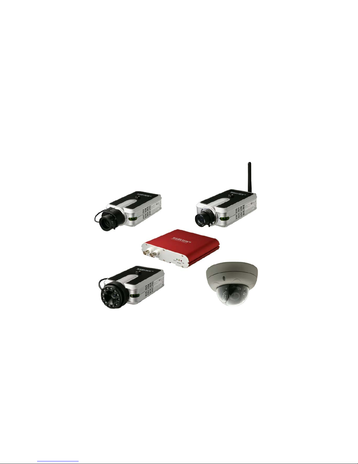
These are the products represented in this user manual:
MNC-L200N: Wired MPEG4/JPEG CCD Network Camera for NTSC standard
MNC-L200P: Wired MPEG4/JPEG CCD Network Camera for PAL standard
MNC-W200N: Wireless MPEG4/JPEG CCD Network Camera for NTSC standard
MNC-W200P: Wireless MPEG4/JPEG CCD Network Camera for PAL standard
MNC-L200NIR: Wired MPEG4/JPEG CCD IR Network Camera for NTSC standard
MNC-L200PIR: Wired MPEG4/JPEG CCD IR Network Camera for PAL standard
MNC-W200NIR: Wireless MPEG4/JPEG CCD IR Network Camera for NTSC standard
MNC-W200PIR: Wireless MPEG4/JPEG CCD IR Network Camera for PAL standard
MNC-L200M20: 2.0 Megapixel Wired MPEG4/JPEG CMOS Network Camera
MNC-W200M20: 2.0 Megapixel Wireless MPEG4/JPEG CMOS Network Camera
MNS-202: Wired MPEG4/JPEG Network Video Server for NTSC & PAL standards
MNC-300VN: Vandal Proof Dome Camera for NTSC standard
MNC-300VP: Vandal Proof Dome Camera for PAL standard
MNC-XXXTDN : True Day & Night Version
(MNC-L200N(P)TDN / MNC-W200N(P)TDN / MNC-300VN(P)TDN)
MNC-XXXTDNIR : True Day & Night with IR Night Vision Version (MNC-300VN(P)TDNIR)
To determine your video standard, refer to the lists below.
PAL: Afghanistan, Algeria, Argentina, Austria, Australia, Bangladesh, Belgium, Brazil, China, Denmark,
Finland, Germany, Hong Kong, Iceland, India, Indonesia, Iraq, Ireland, Israel, Italy, Jordan, Kenya,
Kuwait, Liberia, Malaysia, Netherlands, Nigeria, Norway, New Guinea, Pakistan, Singapore, South
Africa, Southwest Africa, Sudan, Sweden, Switzerland, Thailand, Turkey, Uganda, United Kingdom,
United Arab Emirates, Yugoslavia, Zambia
NTSC: Canada, Chile, Costa Rica, Cuba, Dominican Republic, Ecuador, Japan, Mexico, Nicaragua,
Panama, Peru, Philippines, Puerto Rico, South Korea, Taiwan, USA. Users are asked to read the
following before using the Pro Series Network Camera.

6
Important Notices
1. Camera surveillance laws may differ for each country. Contact the local authorities to avoid
any surveillance law violations.
2. Note that the CCD lens that comes with the Pro Series Network Camera can be damaged
permanently if exposed to direct sunlight. If your application demands prolonged exposure to
sunlight, you should consider equipping it with a sun visor.
3. The Pro Series Network Camera is not weatherproof. Be aware of environmental
specifications included in the manual. For outdoor use, use a weatherproof case to protect the
camera from water, moisture or temperature (higher or lower than specifications). For camera
cleaning, gently wipe with a clean, dry cloth.
4. Be sure to use only the DC adapter provided with your camera. Connecting the camera
directly to AC current may cause electrical damage to the camera.
5. Be careful when handling the camera. Physical shocks can cause serious damage.
6. Be sure to mount the camera securely to avoid any personal injuries. Keep the camera out of
reach of children.
7. If the camera does not operate properly, contact your local distributor. Do not disassemble the
product, as that may void the warranty.
8. Specifications are subject to change without prior notice to enhance the product quality
and stability.
9. The contents of this manual may differ from actual products due to product upgrade or
enhancement.

7
1: Product Overview
1.1 About the Pro Series Network Cameras and Video Servers
The Pro Series Network Cameras and Network Video Server are all-in-one networking devices that
contain a digital color camera (or a connection for analog CCTV cameras), a powerful Web server, an
optimized embedded operating system, hardware for image compression and a physical Ethernet
connection. The products do not need any additional software or hardware. Simply provide power,
connect an Ethernet cable and view from any computer on the network. For the Network Video Server,
you need a conventional CCTV camera as your video input source. The WEBVIEW Pro Series
Network Cameras and Network Video Servers are ideal for surveillance applications that require
high-quality, full-motion video and audio, as well as comparatively low bandwidth demands on the
network. These products provide an easy user interface for remote access to receive the optimal
synchronized video and audio from anywhere, anytime over the Internet with the popular Internet
Explorer Web browser, as easy as surfing any regular Web sites. More than just a high-performance
network camera, the Pro Series Network Cameras and Network Video Server also offer many
advanced features to provide solutions such as remote surveillance, home/business security,
audio/video conferencing, motion detection and more.
NOTE: This user manual includes the Network Video Server whenever it refers to Pro Series Network
Cameras.
1.2 Main Features and Benefits
Convenient Operation
The Pro Series Network Camera does not need any additional software or interaction with any other
server. The only software needed is a common Web browser, such as Microsoft Internet Explorer 5.x
or above.
Open Standards
The Pro Series Network Camera supports TCP/IP networking, SMTP e-mail, FTP, HTTP and other
Internet-related protocols. The camera can be used in a mixed operating system environment with
Windows, Unix, Mac and OS/2. It integrates easily into other www/Intranet applications and CGI
scripts.
Simple Administration
Using a standard Web browser, you can configure and manage the Pro Series Network Camera
directly from its own embedded Web pages. The embedded operating system is upgradeable through
the network; check with your local WEBVIEW dealer for firmware upgrades.
External Devices
The auxiliary Input/Output connector on the camera allows you to connect to a variety of
external devices, such as IR sensors, switches and alarm relays.
Security
Your Pro Series Network Camera includes a self-contained Web server, which means that digital
images can be secured like any other Internet host. Your network administrator, using the unit’s
security settings in combination with an organization’s Internet firewall, normally implements data
protection. The administrator can decide whether individuals, groups or the whole world may access
the camera. The Pro Series Network Camera supports multi-user password protection.
Compression and Performance
With a variable frame rate dependent on the image quality and bit rate, the camera delivers
MPEG4 video at up to 30 images per second.

8
Dual Mode Compression
For application providers, system integrators and other APs, this camera supports three types of video:
1) MPEG4 video; 2) M-JPEG compression; and 3) MPEG4+M-JPEG mode.
Full Duplex Two-Way Audio
Full duplex two-way audio is available by connecting an external microphone and speaker to the
camera.
IEEE 802.3af Standard PoE (Power over Ethernet) Supported
Software
IP Installer for quick installation
Webview manager for viewing and recording multi cameras up to 16 channels in a screen
ETSP Client Motion Detection Recording Utility
Check http://www.networkipcam.com
for latest versions.
2: Physical Description
2.1 Package Contents
Check all items packed inside the box as listed below.
ITEM DESCRIPTION
Network Camera or Video
Server
MPEG4/JPEG dual mode Network
Camera
Installation CD
IP Installer, upgrade program,
Manual, Webview Manager, etc.
Power Supply AC power adapter and power cord
Stand Wall & table stand*
Connection (Console) Cable RS-232 cable
User Manual Hard-copy book
* You can use a standard camera stand or tripod for the Pro Series Network Camera.
9
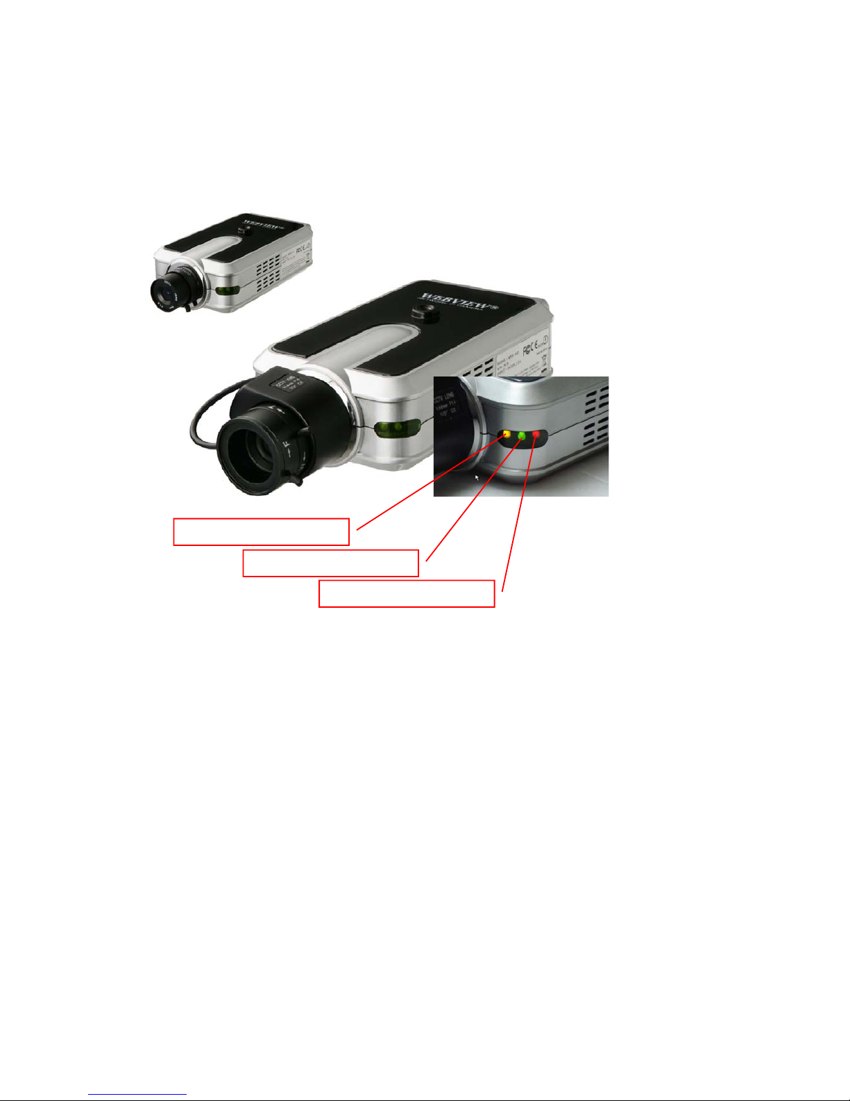
2.2 MPEG4 CCD and CMOS Camera Front View
Power LED (Red): Once power is supplied to the camera, the red LED will light.
Operating Status LED (Green): This LED indicates the camera’s operating status. Once power is
supplied, the LED lights and then blinks once every second as long as the video is transmitted on the
network during normal operation. When there is no video transmission, the LED stops blinking. Under
an event-trigger situation, the green LED becomes red and blinks rapidly. During simultaneous
operation of event-trigger capture and video monitoring, it blinks rapidly and alternates between red
and green. When you click the "camera off" button in the administrator’s menu, the green LED turns
yellow, which shows that your IP camera has stopped transmitting video and audio.
Network Activity LED (Yellow): This LED indicates network activity. When lit, the network is up and
running; when off, the network is down and not working.
Network Activity LED
Operating Status LED
Power LED
10
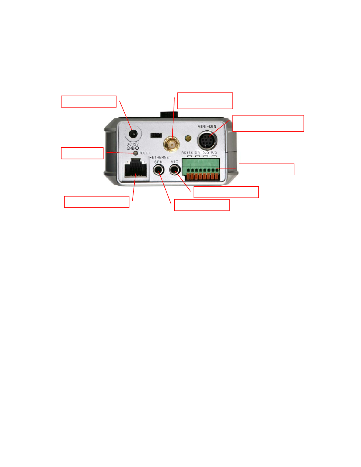
Rear View
Power Connector: Only use the supplied AC adapter to avoid any possible damage from electric
shock.
Network Connector: Connect 10Base-T Ethernet or 100Base-TX Fast Ethernet cable.
GPIO Connector: To connect external devices such as infrared sensors, alarms or motion detectors
(refer to Appendix F: I/O Connector).
Mini DIN Connector: To connect external devices such as the external zoom/focus lens mechanism,
or to connect directly to a serial port for camera configuration via HyperTerminal.
SPK: Use to connect to an external speaker for audio communication. The audio sent over the network
from a connected client computer can be delivered through this externally connected speaker.
MIC: The external microphone for audio input. The live audio can be captured and transmitted to the
connected camera client via the use of this MIC.
NOTE: The Pro Series Network Camera is compatible with 3.5mm stereo microphones. If you are a
3.5mm mono microphone user, use the included 3.5mm stereo plug to two 3.5mm mono jack converter.
Then you can utilize two mono microphones simultaneously.
RESET: Restore the factory default settings.
Power Connecto r
Wireless Antenna
(
Wireless Models
)
Mini DIN for RS-232
Communication
GPIO Connector
External Microphone
External Speaker
Network Connector
Reset Button
11
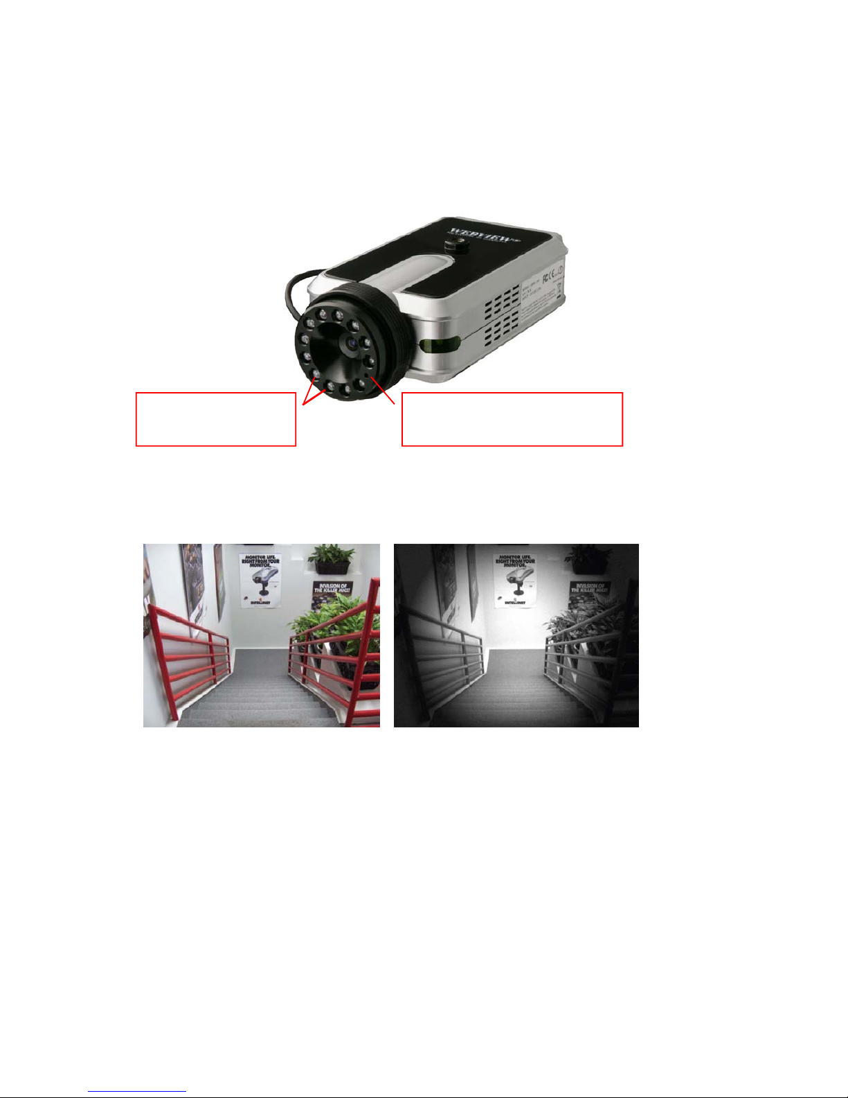
2.3 MPEG4 CCD IR Camera
The IR camera has the exact same connectors and LED’s as the standard models. The difference is
the lens and the CCD image sensor.
Captured image from MPEG4 CCD IR Camera –Left : Daytime, Right : Nighttime
Infrared Emitter Diodes
LED’s automatically
turn on in the dark
Light Sensor
Measures the light level and
activates the IR LED’s in the dark
12
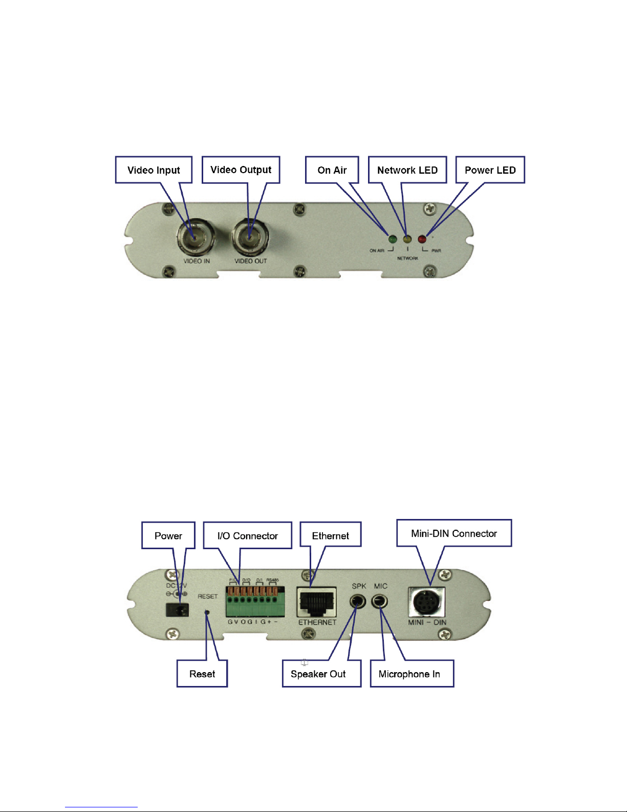
2.4 Network Video Server
Front view
Video Input: To input video signal through a coaxial cable
Video Output: To output video signal through a coaxial cable.
On Air LED (Green): This LED indicates the Video Servers operating status. Once power is supplied,
the LED lights and then blinks once every second as long as the video is transmitted on the network
during normal operation. When there is no video transmission, the LED stops blinking. Under an
event-trigger situation, the green LED becomes red and blinks rapidly. During simultaneous operation
of event-trigger capture and video monitoring, it blinks rapidly and alternates between red and green.
When you click "Video Server off" in the administrator’s menu, this green LED turns yellow, which
shows that the IP Video Server has stopped transmitting video and audio.
Network Activity LED (Yellow): This LED indicates network activity. When lit, the network is up and
running; when off, the network is down and not working.
Power LED (Red): Once power is supplied to the Video Server, the red LED will light.
Power Connector: Only use the supplied AC adapter to avoid any possible damage from
electric shock.
RESET: Restore the factory default settings.
Rear view
13
I/O Connector: To connect external devices such as infrared sensors, alarms or motion
detectors (refer to Appendix F: I/O Connector).
Ethernet (Network Connector): Connect 10Base-T Ethernet or 100Base-TX Fast Ethernet cable.
SPK: Use to connect to an external speaker for audio communication. The audio sent over the network
from a connected Video Server client can be delivered through this externally connected speaker.
MIC: The external microphone for audio input. The live audio can be captured and transmitted to the
connected Video Server client by using of this port.
Mini-DIN Connector: To connect external devices such as the external zoom/focus lens
mechanism, or to connect directly to a serial port for Video Server configuration via
HyperTerminal.
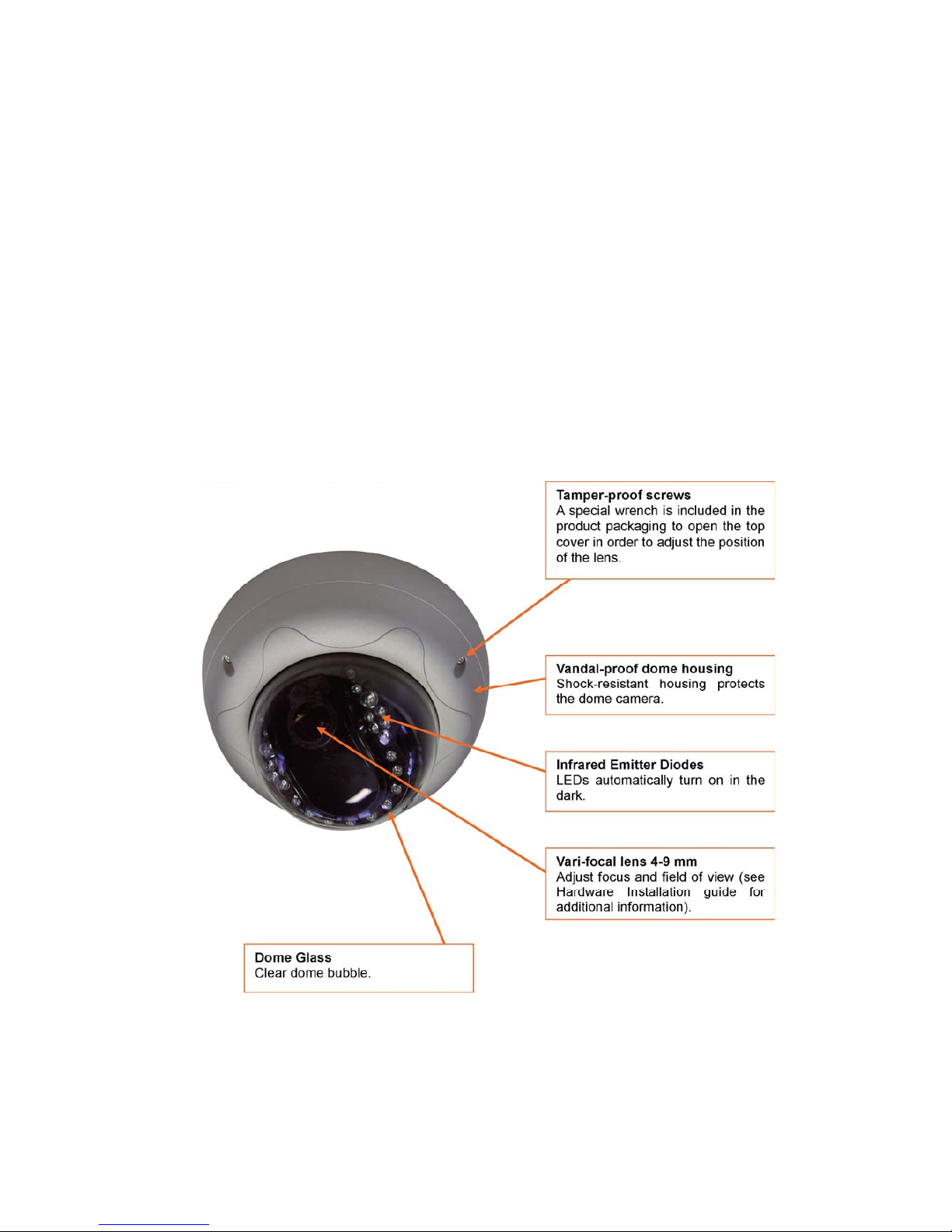
2.5 Vandal Proof Dome Camera
Front View
(Model : MNC-300VTDNIR Night Vision)
14
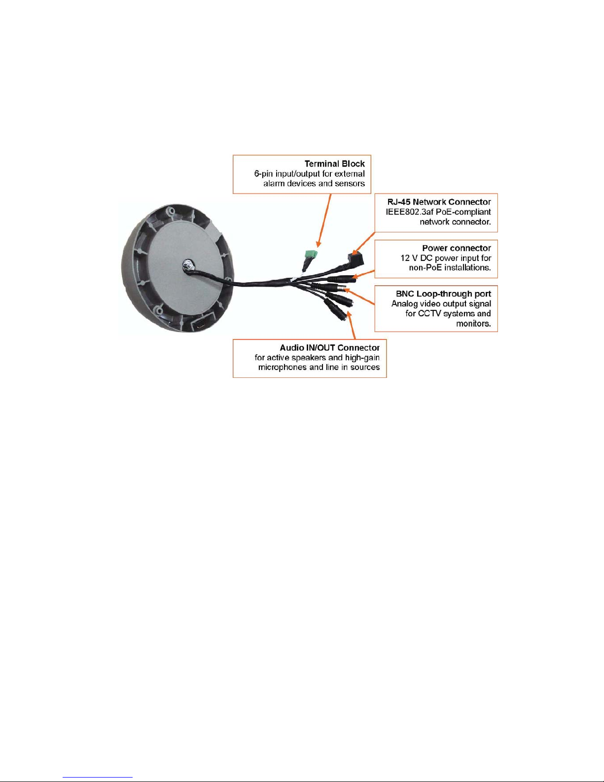
Rear View
RS232 Connector
Serial port connection for HyperTerminal access; See Appendix B.
Network Connector
Connect 10Base-T Ethernet or 100Base-TX Fast Ethernet cable.
Power Connector
Input connector for external 12 V DC Power supply.
Terminal Block
Connect external devices such as sensors and alarm devices, or power external devices through the
camera; See Appendix F for details.
3: Installation Summary and Examples
1. Connect the Ethernet and power to the Pro Series Network Camera.
2. Install and launch the IP Installer program on the enclosed CD.
3. Assign an IP address and network settings.
4. Securely mount the camera. Owners of the indoor fixed dome camera need to refer to the
included Hardware Installation guide.
5. Adjust the lens focus.
15
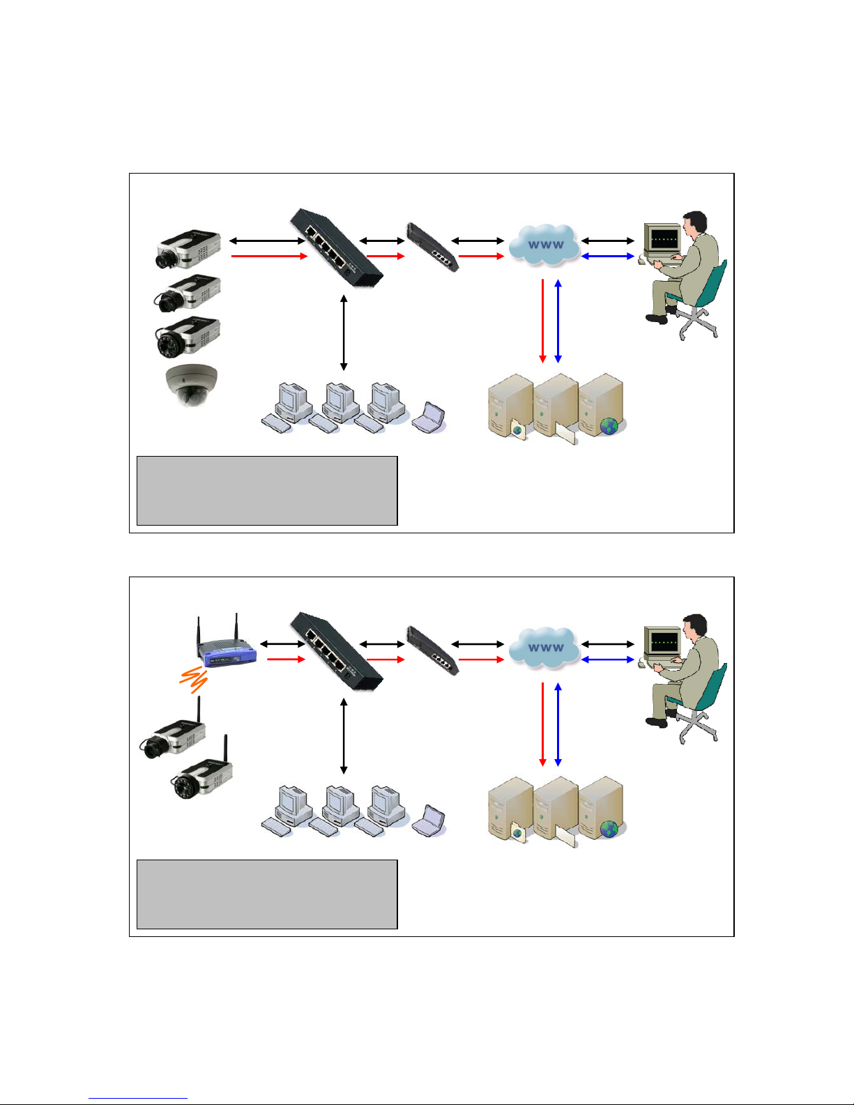
Installation Example: Wired Camera
Installation Example: Wireless Camera
LAN Switch Route
r
Internet (WAN)
Remote Access
Network Cameras
& Video Servers
Local Access
e-mail / FTP / Web Server
Legend (Cable color) :
- Web Browser access to camera
- Access to e-mail, FTP or Web server
- Transmission of AVI files by camera
LAN Switch Route
r
Internet (WAN)
Remote Access
Wireless Network
Cameras
Local Access
e-mail / FTP / Web Server
Legend (Cable color) :
- Web Browser access to camera
- Access to e-mail, FTP or Web server
- Transmission of AVI files by camera
Wireless
Access Point
16
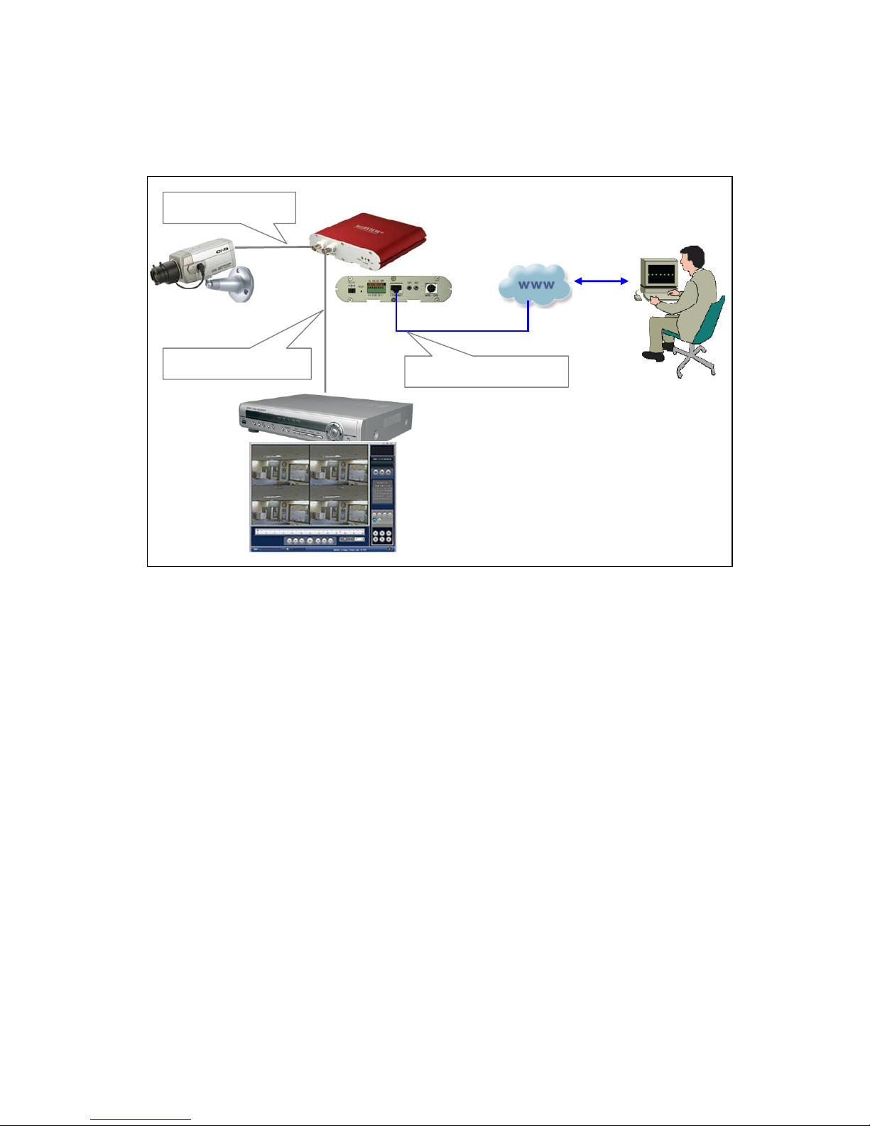
Installation Example: Network Video Server
Remote Access
Network Video Server
CCTV Camera
Analog BNC Input
Analog BNC Output
TCP/IP RJ45 Ethernet
Network
(
WAN/LAN)
DVR
,
VCR, etc.
17
4. Assigning an IP Address and Accessing the Camera’s Homepage
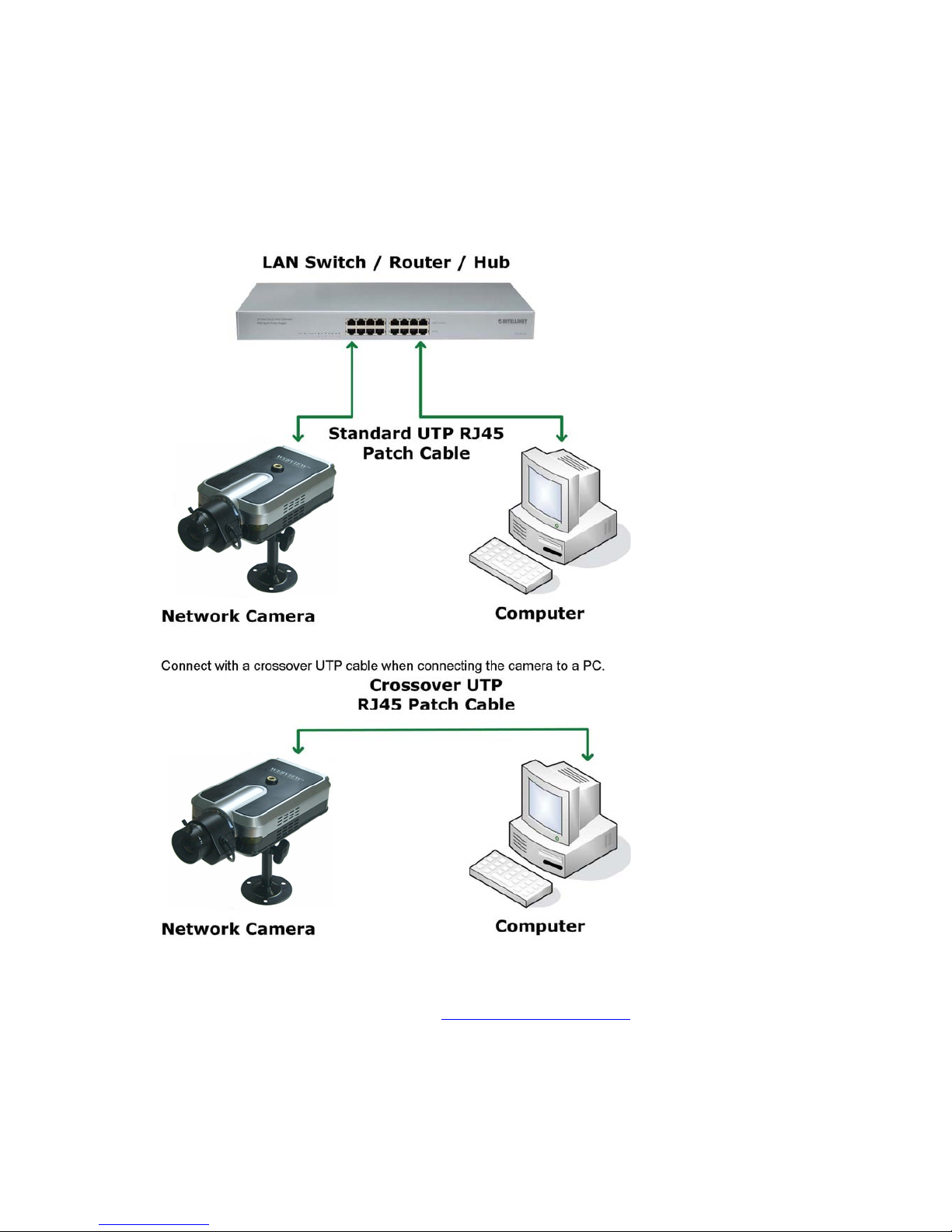
4.1 Connecting the Camera to a PC
Connect with a direct cable (non-crossover UTP cable) when connecting the camera to a switch, hub
or router.
4.2 Setting up the IP Address Using IP Installer
To access the camera, you need to assign an appropriate network IP address. Run the IP address
installation program (IP Installer.exe) on a PC that is connected to the same local network as the
camera. You can download IP Installer from http://www.networkipcam.com
. IP Installer is compatible
with Windows 9x, Me, 2000, XP and Vista.
18
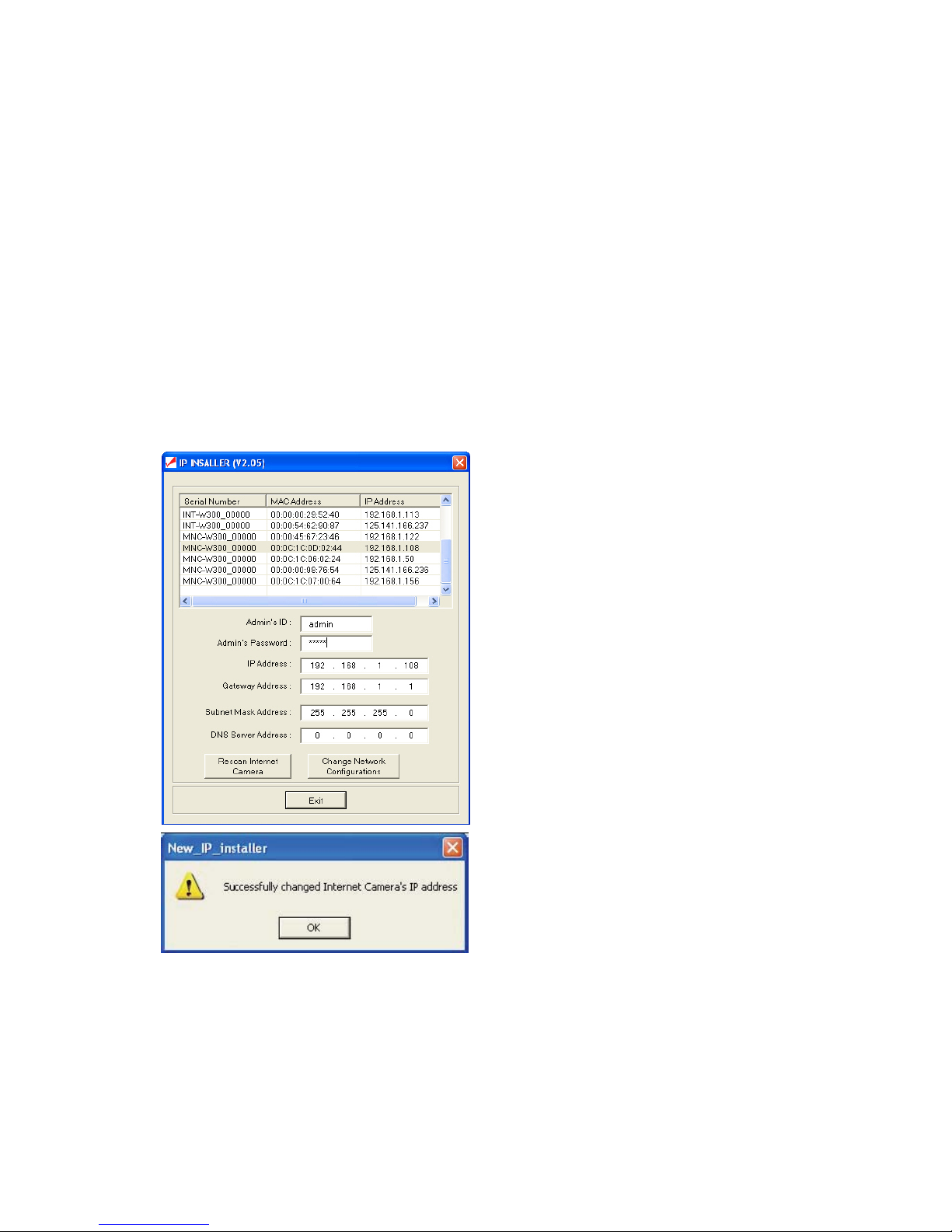
1. Run IP Installer after the camera is booted (wait until the Operating Status LED blinks every
second).
2. Once IP Installer is run, the panel shows every camera connected on the local network. From the
cameras listed, select one to assign a new IP address (every Pro Series Network Camera has a
factory default IP address).
NOTE: The MAC address can be found on the underside label of the camera. To choose a camera,
click on its MAC address on the list.
Enter the administrator ID and password in the blank (default ID and password are both “admin") to
assign or change the IP address for the camera and setup.
Enter the IP address, gateway address, subnet mask address, DNS server address and server IP
address assigned by the network administrator. (When the addresses are not assigned properly, you
cannot access the camera.) The server IP address does not need to be filled out at this time.
After entering all addresses for the camera, click on "Change Network Configurations."
The message shows up if all the information is set up properly.
Then click the "OK" button.
NOTE: After changing the network configuration, it may take a little time to reboot the camera in order
to access the camera’s homepage.

19
4.3 Accessing the Camera’s Homepage
Access the camera to monitor real-time images over the Internet and configure the camera settings
through any standard Web browser on a local or remote network. The following Web browsers are
supported.
ٛ - MS Internet Explorer 5.x, 6.x and 7.x (ActiveX + Java)
ٛ - MOZILLA Firefox 1.x., 2.x (Java)
ٛ - MOZILLA 1.x (Java)
ٛ - Opera (Java)
ٛ - Konqueror (Java)
The WEBVIEW Pro Series Network Camera supports two connection methods: ActiveX for
Microsoft's Internet Explorer users on Windows systems; and Java for all other Web browsers and
operating systems, including MacOS and Linux, and Windows when using a different Web browser
than MS Internet Explorer.
ActiveX offers faster performance and enhanced features, such as video recording via Web
browser and two-way audio. Using ActiveX, however, requires the user to be logged in as a
computer administrator. Not everybody has this ability. Furthermore, ActiveX is often banned from
use in corporate environments for security reasons.
Java represents the universal alternative to ActiveX. It can be used on nearly all common computer
operating systems and with almost any common Web browser. The camera primarily supports Java
by Sun Microsystems, but it is also compatible to Microsoft's Java VM. Sun's Java can be downloaded
from http://www.java.com
.
Note: In order to utilize Java, the camera must be operating in JPG Stream mode (see section
6.6. System Configuration).
Before you attempt to connect to the camera with your Web browser, make sure that your setup meets
the following requirements:
1. You have assigned a valid IP address to your camera. The IP address of the camera is in the
same subnet as your computer.
2. You use MS Internet Explorer and have admin authority to install the ActiveX control.
3. You chose to access the camera using Java and have either Java version (SUN or Microsoft)
installed in your computer.
Starting the Web Bro wser
Start your Web browser, entering your camera’s IP address on the address bar in order to
access the login page. The default IP address is 192.168.1.221.
Login Page
After you open the camera address, you will be connected to the login page of the camera. The login
page looks slightly different, depending on the Web browser you are using, and depending on the
streaming mode the camera is set to (see section 6.6 System Configuration).
Below is an overview of the different login screens and stream modes.
20
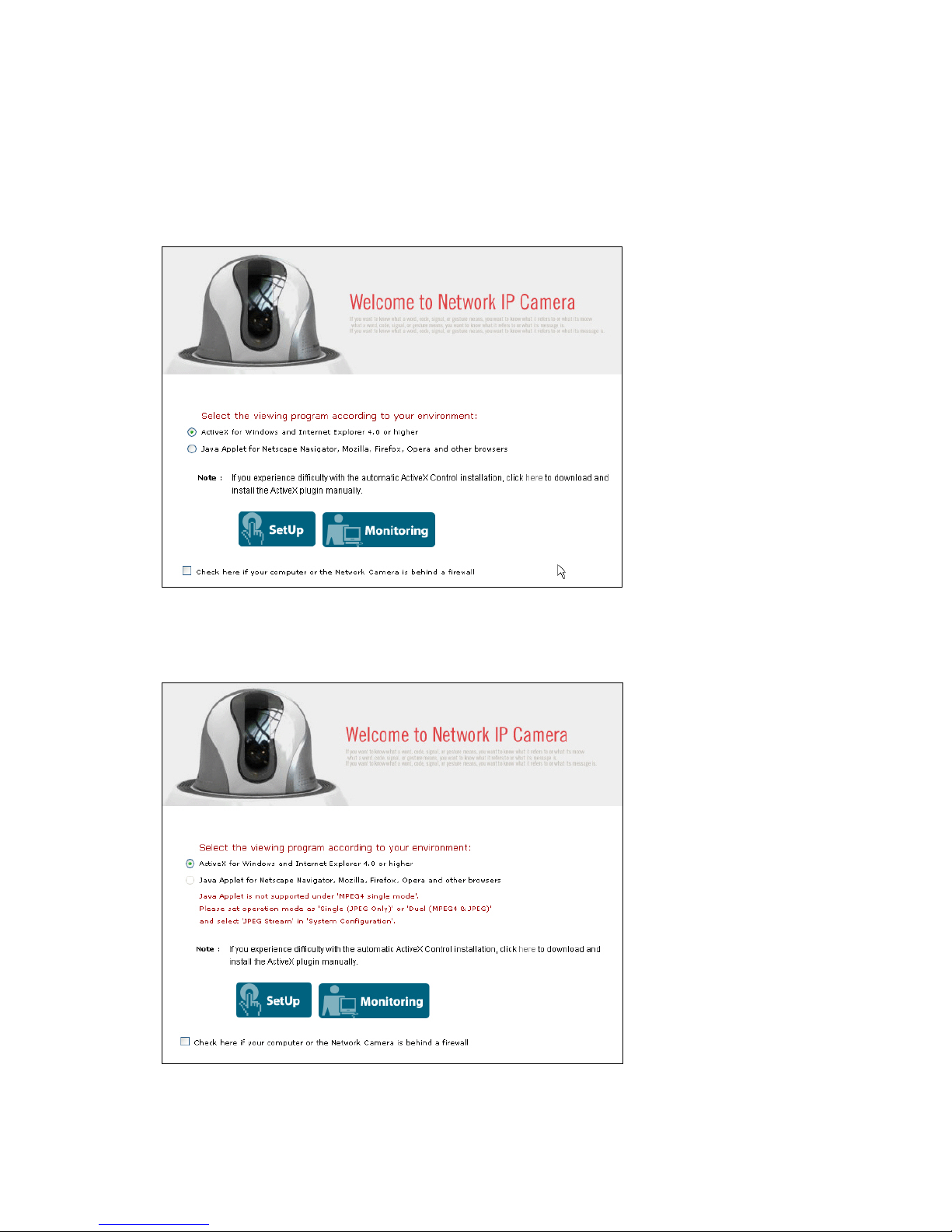
MS Internet Explorer – JPEG Stream Mode
Both options, ActiveX and Java, are available in this operational mode. If you can run and install
ActiveX controls, you should select ActiveX as your preferred viewing program, as it offers higher
frame rates and better functions.
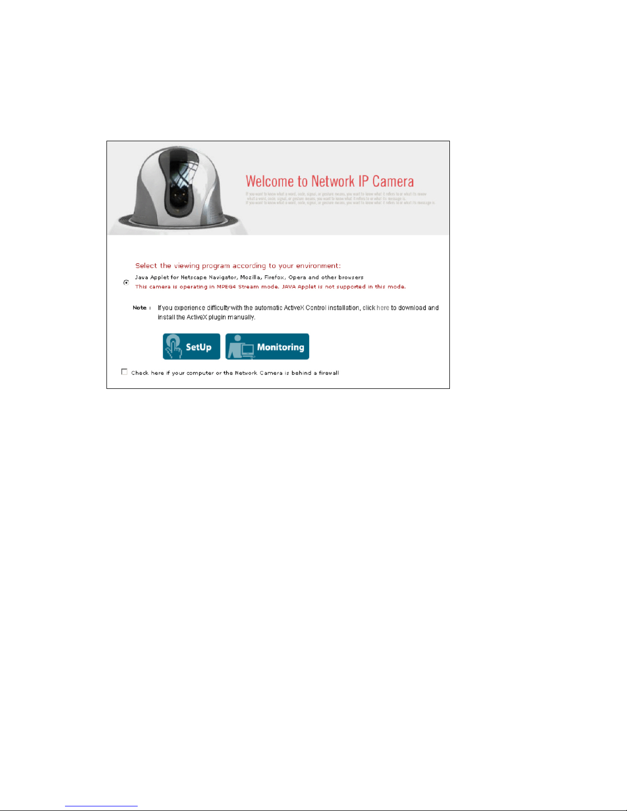
MS Internet Explorer – MPEG4 Stream Mode
Java is not available in MPEG4 Stream mode and the option is therefore grayed-out.
21
Non-MS Internet Explorer – JPEG Stream Mode
Java is the only choice given.
Non-MS Internet Explorer – MPEG4 Stream Mode
Java is the only choice given, but the warning message tells you that even though you are able to login
you won't be able to see the live image as shown in the above. You still can access the administration
menu to make changes to the settings.
SetUp & Monitoring
On the log-in page, there are two modes of starting the IP camera. The one is ‘SetUp’, which starts IP
camera with configuration setting and the other is ‘Monitoring’, which leads you to live view of IP
camera video. Only administrator can start with ‘SetUp’ menu.
Username and Password
Enter a username and password to access the camera. The camera has two default user
accounts.
. Administrator account: View live image and change the camera settings.
Default Username: admin / Default Password: admin
. Guest account: View the live image, but no access to any camera settings.
Default Username: guest / Default Password: guest
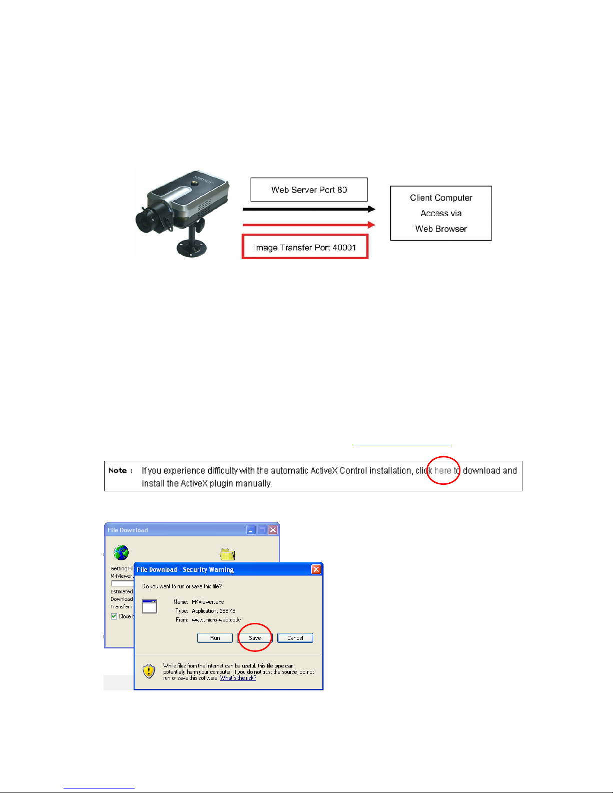
Behind a Firewall
If your PC is connected to a network with a firewall, you may not view real-time video properly because
the video TCP port is blocked. The camera operates on two important ports. One port is the Web
server port (default = 80).The other port is the image transfer port (default = 40001). The camera sends
the user interface pages (such as the login page) via TCP/IP port 80 and the image stream through the
Image Transfer Port 40001. If for whatever reasons the camera cannot send you data via the Image
Transfer Port (e.g., because the port may be blocked on the client computer) or, in case you access
the camera remotely over the Internet, the port may not be properly opened and forwarded in the
22
router, and you will not be able to see the live image of the camera. A blocked image transfer port is
the most common cause for display problems.
As a rule: Whenever you can see the login page in your Web browser but no live video shows up on
the main camera live screen, you should activate this option.
ActiveX Installation for MS Explorer Users (automatic)
The first time you login to the camera using ActiveX, you are notified that a required plug-in / ActiveX
control is required. You need to allow the installation of ActiveX by clicking "Yes" to the question "Do
you want to install the program?" on the pop-up window. The installation will then take place. It is
normal for this process to take up to 30 seconds. After the installation you will be taken to the Network
Camera Homepage. If you do not see the message concerning the ActiveX installation, this can have
different causes:
- you are not logged in to your computer as an administrator
- the security settings on your system (Internet Options) prevent the installation of signed
ActiveX controls
ActiveX Installation for MS Explorer Users (Manual installation)
If the ActiveX program fails to install automatically, you can install it manually. Administrator rights
are still required.
First you need to download M4Viewer.exe from the Web site www.networkipcam.com
. You can find
the link on the login page of the camera as shown below.
Save M4Viewer.exe on the computer's hard drive.
23
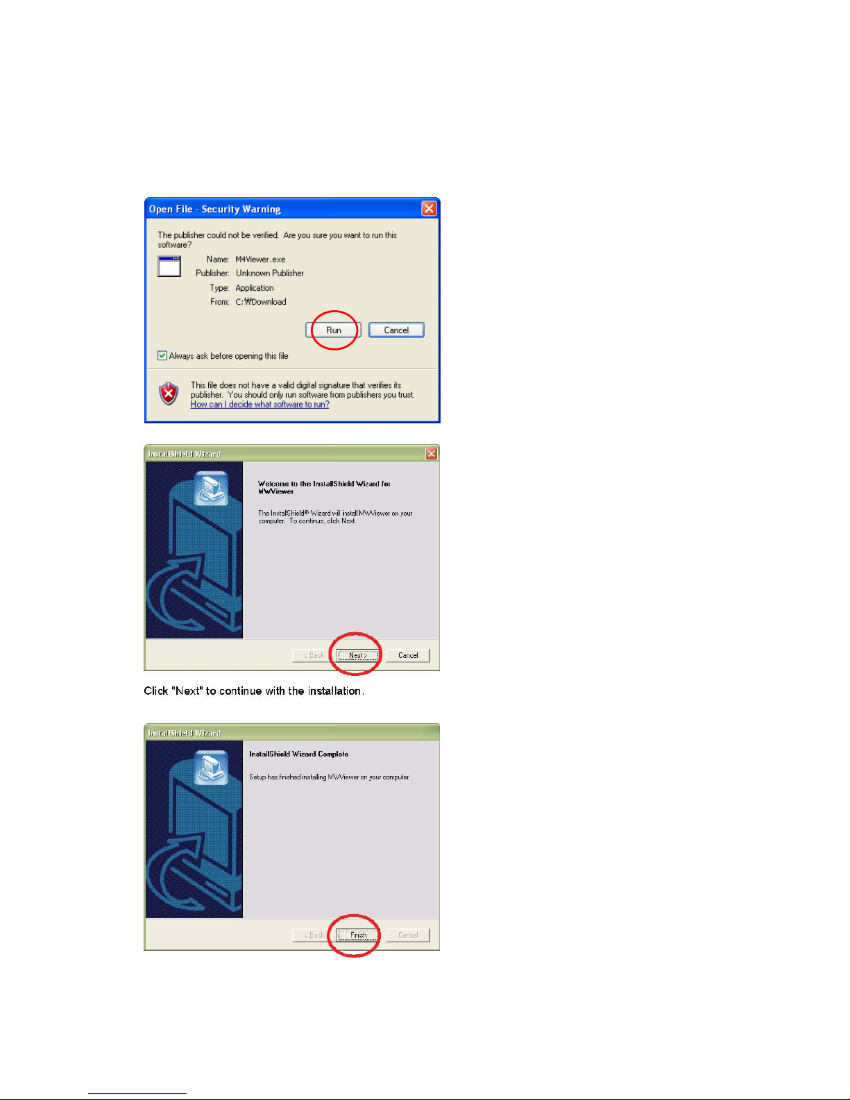
Once the download is completed, you need to run the program by double-clicking it.
You may see the following message:
Click on "Run" to proceed with the installation. Click "Next" to continue with the installation.
24
When you see the message above, you have successfully installed the ActiveX control.
Restart MS Internet Explorer and re-connect to the camera.
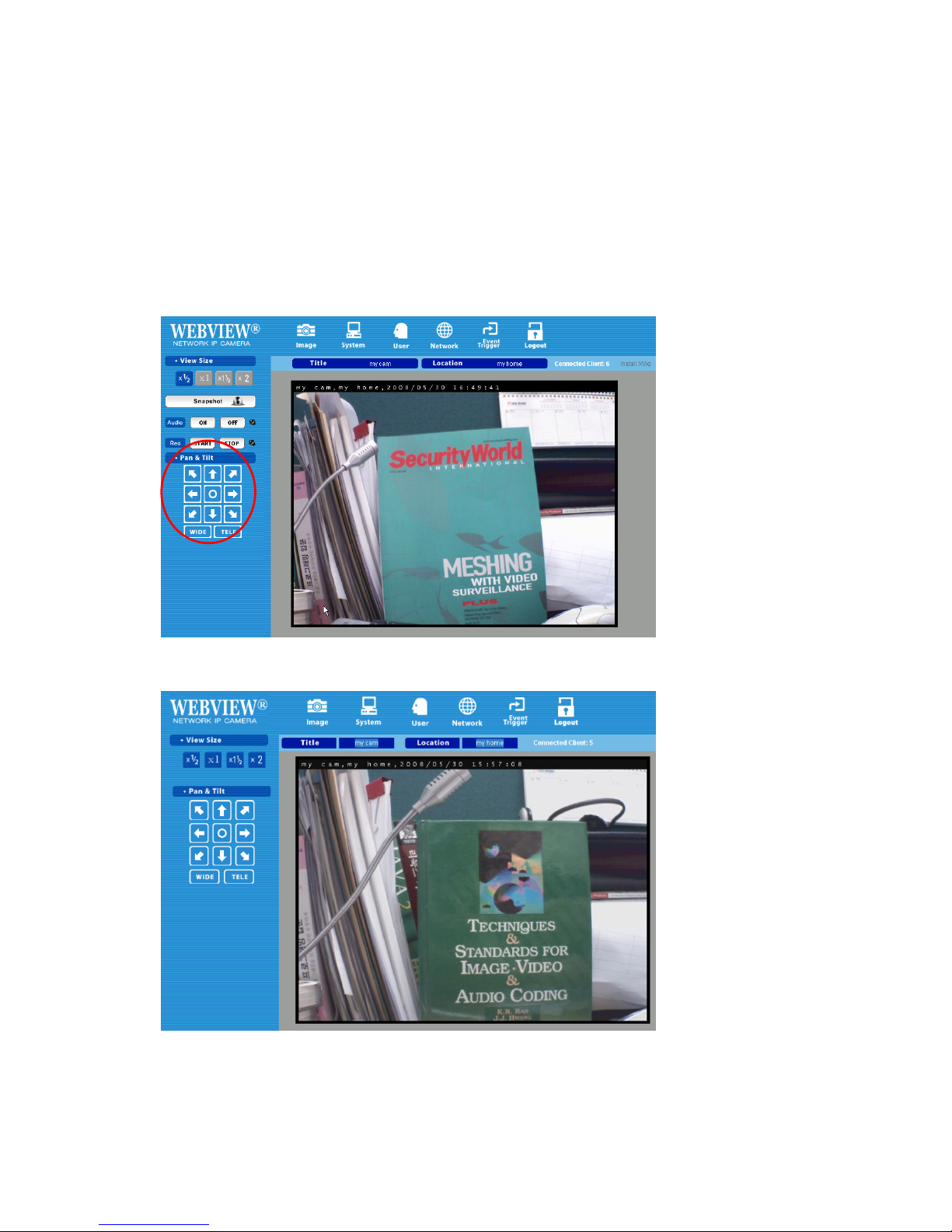
4.4 Homepage Options (MPEG4 Cameras)
Once the login procedure is complete, you can view the Pro Series (MPEG4) Network Camera
homepage. Below is an overview of the different pages for the different models for both Java and
ActiveX.
ActiveX version
(Only Digital PTZ cameras and video servers show ‘Pan & Tilt’ control panel)
Java version : Snapshot, Audio and Recording are not supported in this mode.
25
Video Size
You can select a viewing image size from 0.5 to 2. This function represents a digital zoom. It does not
change the physical resolution of the image. At high resolution (D1) the options "x1.5" and "x2" are not
available.
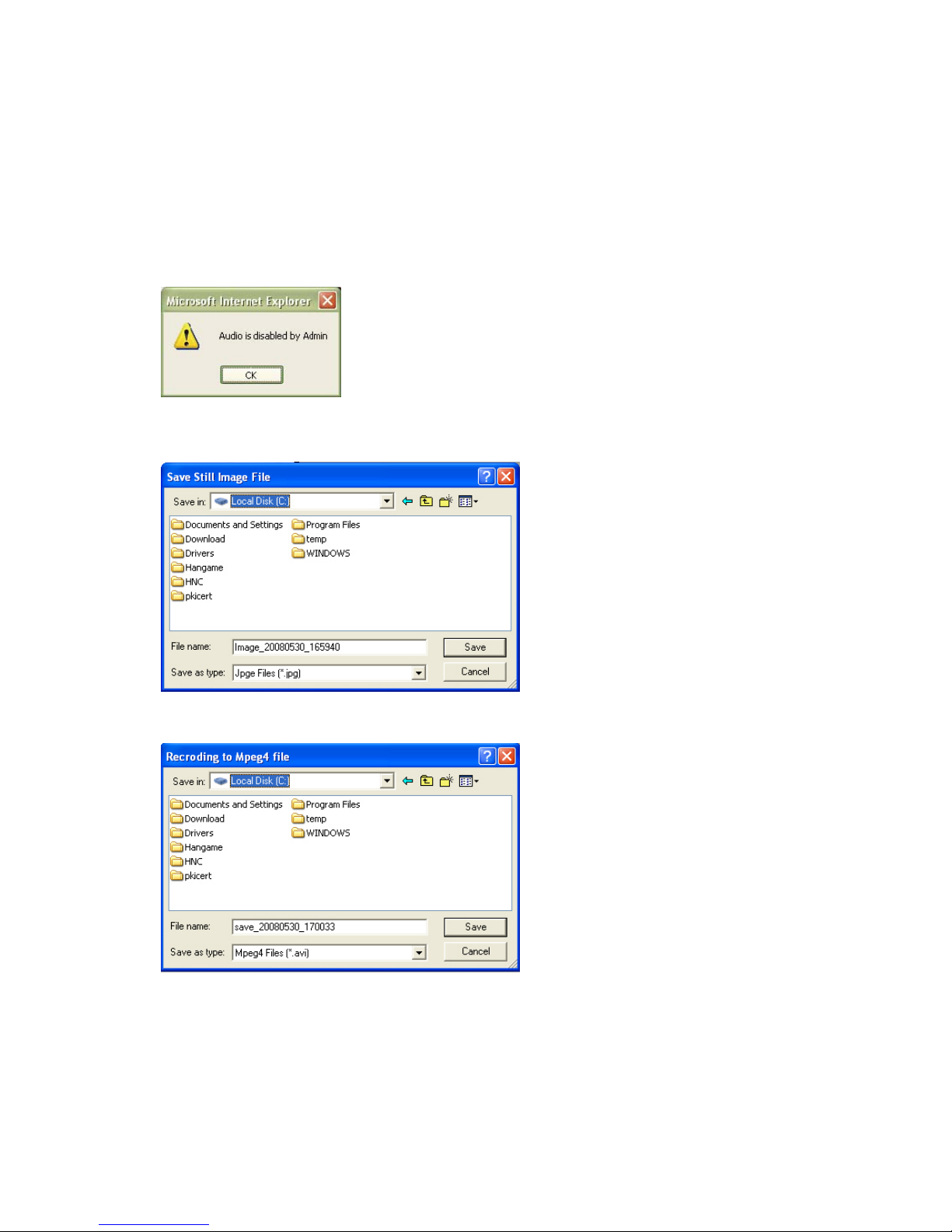
Audio
Select audio "on" for starting audio communication; select "off" to stop audio communication over the
network with the external microphone and speaker connected to the
camera. If Audio is deactivated in the system settings of the camera,
clicking the "on" button results in the error "Audio is disabled by
Admin."
Save Snapshot
To save only one image, press "Save Snapshot" and then select a folder. The image is saved as a
JPEG file (with the default file name
composed of the date and time:
image_yyyy_mm_dd_hh_mm_ss.jpg).
Record Video
Users can save real-time images from the camera on a PC. Click "Start," then select the folder to save
the images in. (The image is saved as an
AVI file.) Once the camera starts to save
images, the green LED indicator will start
blinking. To stop saving, click "Stop" and
the LED indicator will stop blinking. You can
view a saved image with Windows Media
Player or Real-Time. For the initial playback
of a saved image, click "Install XviD."
NOTE: In Record Video mode, the video recording will be saved into a file different name every 20
minutes (for example: file name 2002_04_22_15_00, file name 2002_04_22_15_20…). If you assign
the file name in the first instance, not using default file name, the file name for the first 20 minutes will
be the assigned name but the names of subsequent files are composed as "user assigned name_
yyyymmdd_hhmmss.avi."

26
Administrator Menu
This button is for accessing the administration menu. However, only the user who has authority as an
administrator can access the page with administrator’s ID and password (see Configuring
Administration Menu).
Logout
User can go back to the Login page by using the "Logout" button.
Connected Clients
Shows how many users are currently viewing the camera image.
Install XviD
In order to view the video, you have recorded in your computer, the XviD codec must be installed. If the
video does not play back correctly in Windows Media Player, you will need to install the XviD codec on
your system. The link on the camera homepage lets you download the XviD installer to your computer.
You then need to install the codec and restart your computer. After that, your computer will play back
the recorded camera
video with Windows
Media Player.
1. Download the file to the computer.
2. Run the installer and follow the
instructions on the screen.
Install Xvid
27
Pan & Tilt (only certain models)
With these buttons, you can control the digital Pan Tilt Zoom of the camera. Click on "TELE" to zoom in
to the image and use the direction buttons to change the viewing area. Click on "WIDE" to zoom out to
see the entire image. This function is only available in the MPEG4 CMOS camera models.
5: Adjusting the Camera Lens
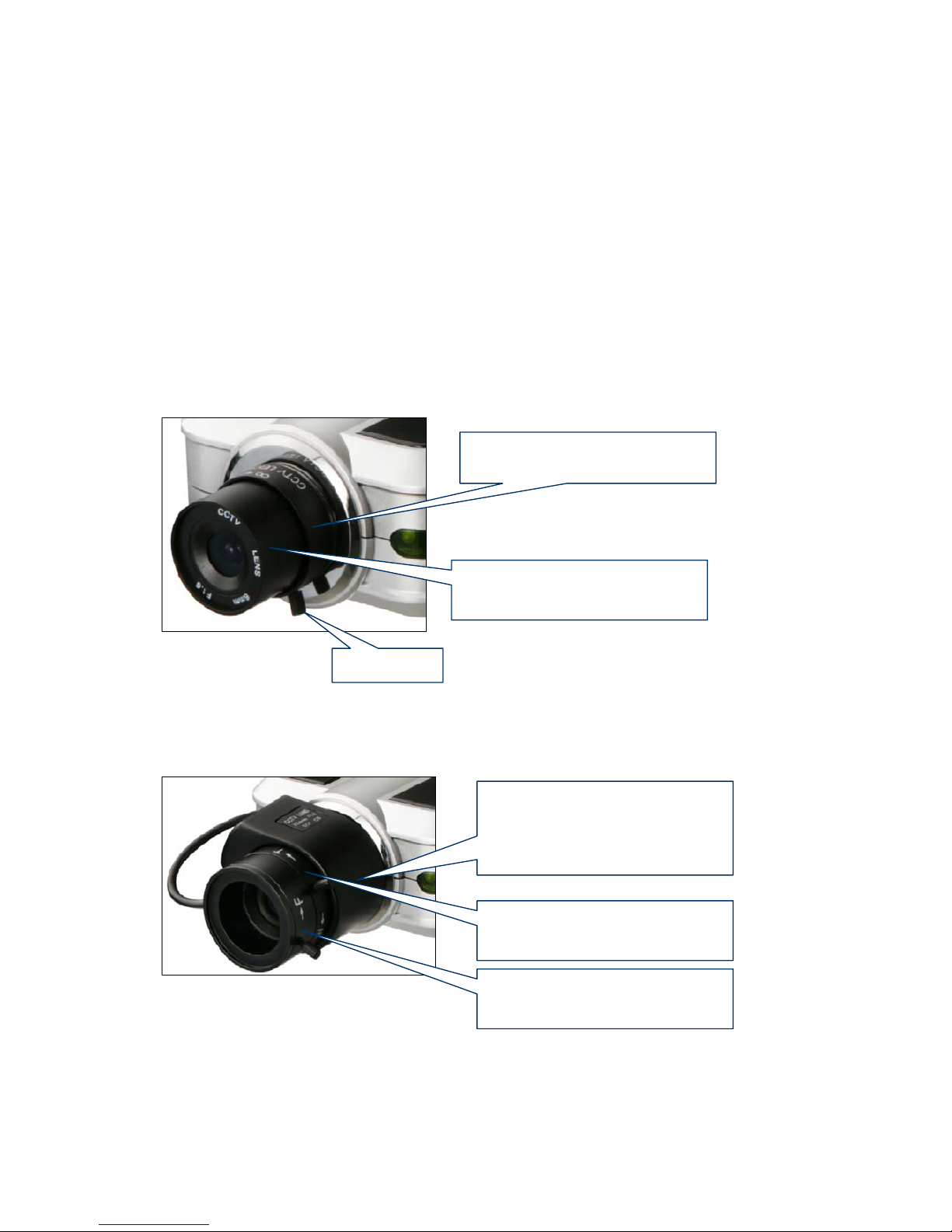
5.1 Adjusting the Focus
To get the finest image, adjust the lens focus according to your environment.
Standard Fixed Iris Lens
Before adjusting, turn the set screw counterclockwise, then turn the lens in either direction till you get
the most well-defined image edges while viewing the picture quality on your Web browser. When you
finish adjusting the lens, turn the set screw clockwise to fix it in place.
Auto-iris Vari-focal Lens
Before adjusting, turn the two set screws counterclockwise, then turn the wide-tele ring first to get the
best angle of view. After setting the angle of view by adjusting wide-tele ring, then turn the near-far ring
clockwise or counter-clockwise until you get the finest image.When you finish adjusting the lens, turn
the set screw clockwise to fix it in place.
Set Screw
Turn this part either clockwise or
counter-clockwise until you get
the best ima
g
e
Turn this part counter-clockwise
to unscrew and replace lens
T urn this p ar t counter-clockwise
to unscrew and replace lens.
Be sure to unfix the AI lens
connector from the camera body
first.
T urn this part either clockwise or
counter-clockwise until you get
the best an
g
le of view.
T urn this part either clockwise or
counter-clockwise until you get
the finest ima
g
e.
28
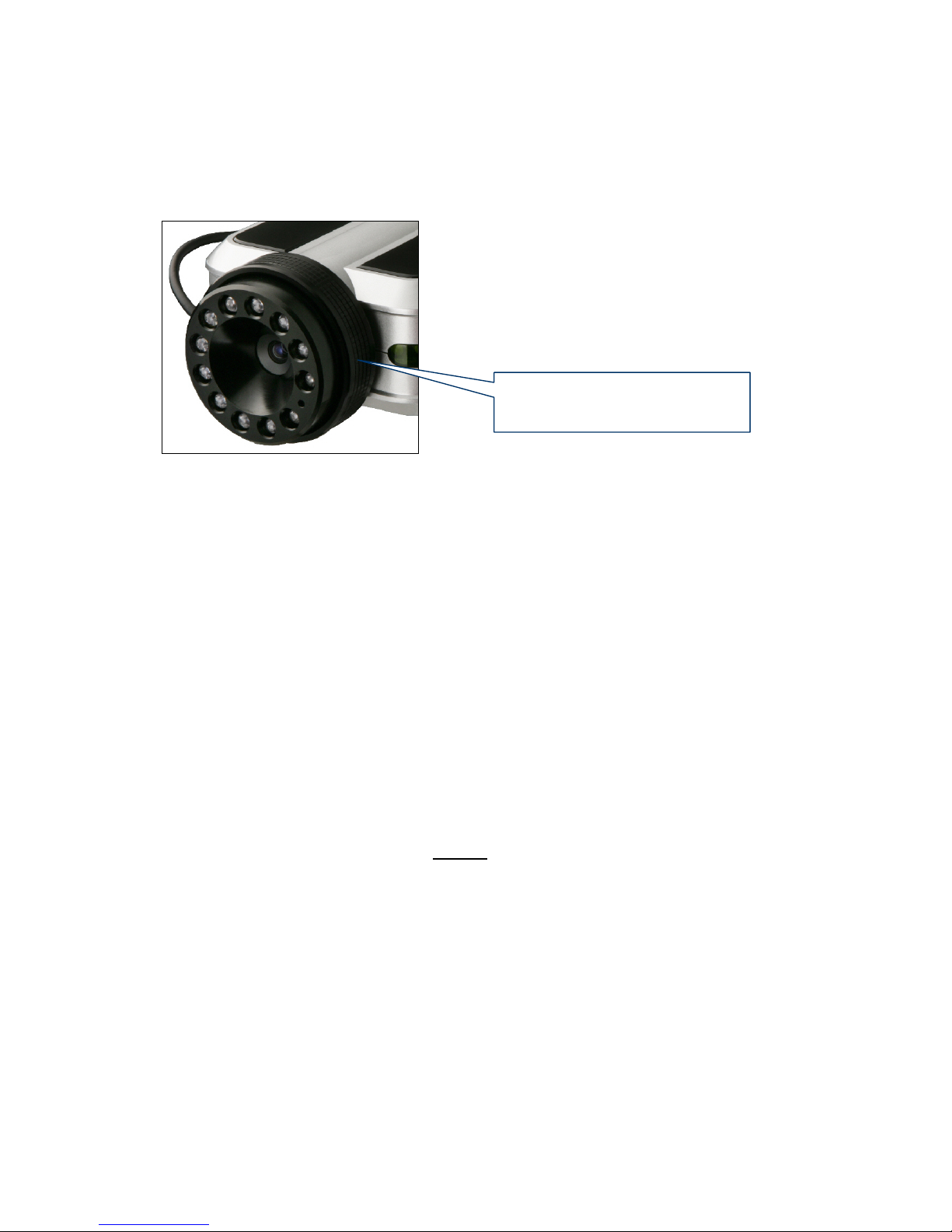
Night Vision IR Lens
NOTE: Do not force the lens beyond either the clockwise or counterclockwise limit. Also, a good level
of focus is normally achievable throughout several planes within the camera’s focusing spectrum.
Since optimum focusing is dependent upon the camera’s field of view, it is important to scan the
focusing plane from the closest to furthest perspectives before attempting any fine-tuning.
5.2 Replacing the Lens
The Pro Series Network Camera is designed with a CS mount. The lens supplied with your product
can be replaced with any standard C or CS lens, typically used within the surveillance industry. Follow
the instructions below to replace the supplied lens with any C- or CS-type lens.
1. Unscrew the camera lens by turning the lens counterclockwise (see above figure &
instruction).
2. For C lens only: Attach the new lens to a C-CS adapter.
3. Screw the new lens onto the camera. If applicable, adjust the iris according to the prevailing
light conditions.
4. Focus the lens as instructed above.
5. Reload your Web browser and monitor the results from the product homepage.
NOTE: The Night Vision Infrared Camera (MNC-L200IR MNC-W200IR) is equipped with a
special lens which cannot be replaced and must not
be removed.
Turn this part cautiously either
clockwise or counter-clockwise
until
y
ou get the finest image.
29
6. Administrator Menu
You can control the configurations of the camera using the administrator tools, which can be accessed
only by an authorized user. If non-authorized users try gaining access, you may see a warning
message "You are not an administrator."
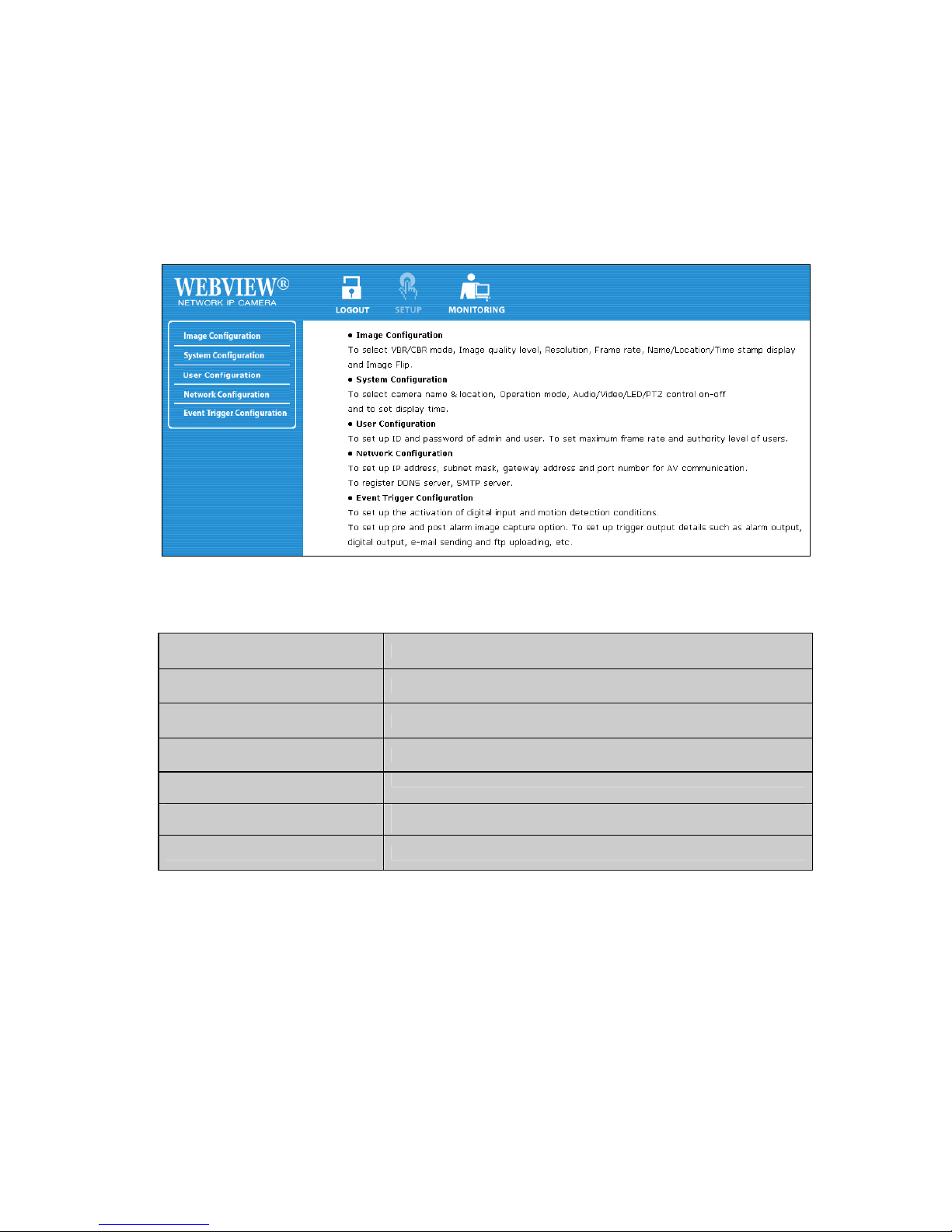
6.1 Overview of the Administration Menu
The table below provides a one-step overview of the Administrator Tools:
Image Configuration To Configure compression rate, image size, brightness, contrast, etc.
Network Configuration To configure camera IP, Web server port, image transfer port
User Configuration To configure user ID and password
System Configuration To configure the camera name, location and time settings
Event Trigger Configuration
To configure trigger condition, image capture option, trigger output, etc.
Wireless Configuration (wireless
models only)
To configure wireless parameters such as wireless mode, SSID,
encryption, etc.
Monitoring To go back to the monitoring page
NOTE: It is highly recommended that you change the administrato r password for your camera as soon
as possible to prevent unauthorized users from accessing the administrator menu. You can change the
administrator password in the User Configuration.
 Loading...